

Page 1

User’s Manual
8/16-Port Enterprise KVM Switch
Model No.: SP218D/SP226D
http://www.micronet.info
Page 2

Certifications
FCC
This equipment has been tested and found to comply with Part 15 of the FCC Rules.
Operation is subject to the following two conditions:
(1) This device may not cause harmful interference
(2) This device must accept any interference received. Include interference that may
cause undesired operation.
CE
This equipment is in compliance with the requirements of the following regulations:
EN 55 022: CLASS B.
RoHS
All contents of this package, including products, packing materials and
documentation comply with RoHS.
Page 3

Table of Contents
Chapter 1 Introduction................................................................................... 1
1.1 Package Contents..........................................................................................1
1.2 Key Features .................................................................................................1
1.3 Specification .................................................................................................2
Chapter 2 Hardware Installation.................................................................... 3
2.1 Physical Description .....................................................................................3
2.1.1 Front LED ...........................................................................................................3
2.1.2 Rear Description................................................................................................3
2.2 Cable Diagram ..............................................................................................4
2.2.1 3-in-1 DB15 Cable.............................................................................................4
2.2.2 PS/2 (keyboard) to USB adapter....................................................................4
2.2.3 Daisy Chain Cable ............................................................................................4
2.3 Rack Mount Installation................................................................................5
2.4 3-in-1 HDB15 Cable Installation.................................................................. 6
2.5 Installation Steps...........................................................................................7
2.6 Daisy Chain Connection...............................................................................8
Chapter 3 Operation...................................................................................... 9
3.1 Push Button................................................................................................... 9
3.2 BANK 7-seg LED.........................................................................................9
3.3 Hot Plug ......................................................................................................10
3.4 Hotkey.........................................................................................................10
3.4.1 Hotkey Example ..............................................................................................10
3.4.2 Hotkey List........................................................................................................11
3.5 OSD Menu ..................................................................................................11
3.5.1 Login Window ..................................................................................................13
3.5.2 Port Name ........................................................................................................14
3.5.3 Language..........................................................................................................15
3.5.4 PORT NAME EDIT..........................................................................................15
3.5.5 Port Search ......................................................................................................16
Page 4

3.5.6 User Security....................................................................................................16
3.5.7 Access List .......................................................................................................17
3.5.8 Hotkey...............................................................................................................17
3.5.9 Time Setting.....................................................................................................18
3.5.10 OSD Mouse......................................................................................................18
Chapter 4 Troubleshooting.......................................................................... 19
Page 5

Chapter 1 Introduction
Micronet proudly introduces SP218D/SP226D, 8/16-Port Enterprise KVM
Switch. It is ideal for utilizing server or normal PC for centralized control on a
single administrative area. With its high port quantity, it can easily scale up to
enterprise level network environment. It provides both PS/2 and USB
connectors for mouse and keyboard usage (Convert PS/2 to USB via convert
connector). The KVM switch provides OSD and hotkey control to allow users
to operate the device without hassle. For security, the device provides
password protection for administrators and can be set via the OSD interface.
1.1 Package Contents
Prior to the installation of the device, please verify the following items are in
the package:
y 8/16-Port Enterprise KVM Switch
y Quick Installation Guide
y Manual CD
y AC – DC Power Adapter
y Rack Mount Accessories
y Footpads Set
1.2 Key Features
y Supports multiple Operation System environments with PS/2: MS
Windows, Netware, UNIX and Linux
y Support iMAC, Power MAC and Sun Micro Systems with USB port
y Provide driver-free operation where no external software is required, it
can be easily operated via OSD interface, Hotkey and Push Button
y Provide Hotkey selection for commonly used keys (Scroll-Lock/ Cap-
Lock/ Num-Lock/ L-Alt/ L-Ctrl/ L-Win/ R-Alt/ R-Ctrl/ R-Win)
1
Page 6
y Support Daisy Chain function with both Bus (8-layer) and Tree (2-
layer) topologies
y Provide search and naming function for PCs via OSD interface
y Combined Push Button and LED indication for switching between PC
y Support Hot Plug & Play for USB mouse and keyboard
y Multi language support for OSD interface: English, France, Germen,
Spanish, Italian, Russian, Japanese and Simplified Chinese
1.3 Specification
z 8/16 x PC Ports (HDDB-15)
z 1 x Local Monitor VGA port (HDDB-15)
Interface
KVM Cable
Advanced Features
Auto Scan 5 ~ 99 seconds
Video Resolution 1920 x 1440
Keyboard and
Mouse Emulation
Environment
Power DC Power Adapter: 12 VDC, 1A
z 1 x Local Keyboard PS/2 port (mini din 6-pin)
z 1 x Local Mouse PS/2 port (mini din 6-pin)
z 1 x Daisy Chain port (Bus 8-layer and Tree 2-layer
topologies, DB15 Female Connector)
z KVM Switch side
¾ 3-in-1 (Monitor, Mouse, Keyboard) HDDB-15
connector.
z PC side
¾ Monitor (HDDB-15)
¾ Keyboard (PS/2)
¾ Mouse (PS/2)
z Push Button
z Hotkey (Supports other hotkey selection)
z On Screen Display (OSD) Interface
z User Account with Password Protection
z Access Control List for User Accounts
z Support Hot Plug & Play (USB only)
PS/2 or USB (Use converter to change between PS/2
and USB)
z Operating Temp.: 0 ~ 50 °C
z Storage Temp.: -20 ~ 60 °C
z Humidity: 0 ~ 95%, Non-Condensing
2
Page 7
Chapter 2 Hardware Installation
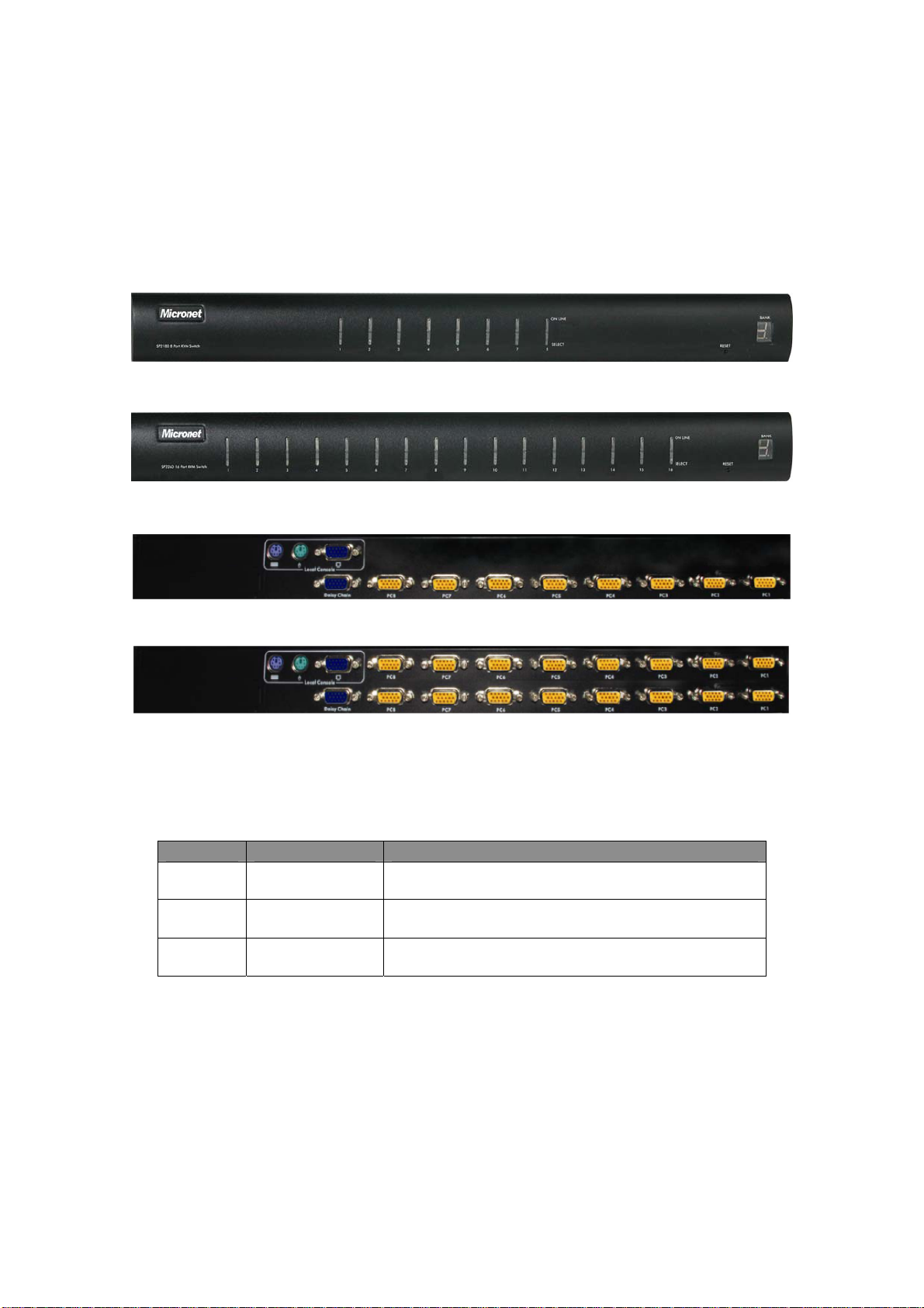
2.1 Physical Description
8-Port Front View
16-Port Front View
2.1.1 Front LED
LED Status Operation
Online Red/On
Select Blue/On
Bank Bank No./On
2.1.2 Rear Description
8-Port Rear View
16-Port Rear View
On to indicate that a PC is successfully
connected to the KVM.
On to indicate the selected PC on the local
monitor.
Indicates bank number of the device (Useful
for Daisy Chain connection).
y Local Console: This interface is for connecting local monitor,
keyboard and mouse that will be used to control the KVM.
y PC: For connecting 3-in-1 Cable from KVM to PC.
3
Page 8
y Daisy Chain: For connecting multiple KVM together.
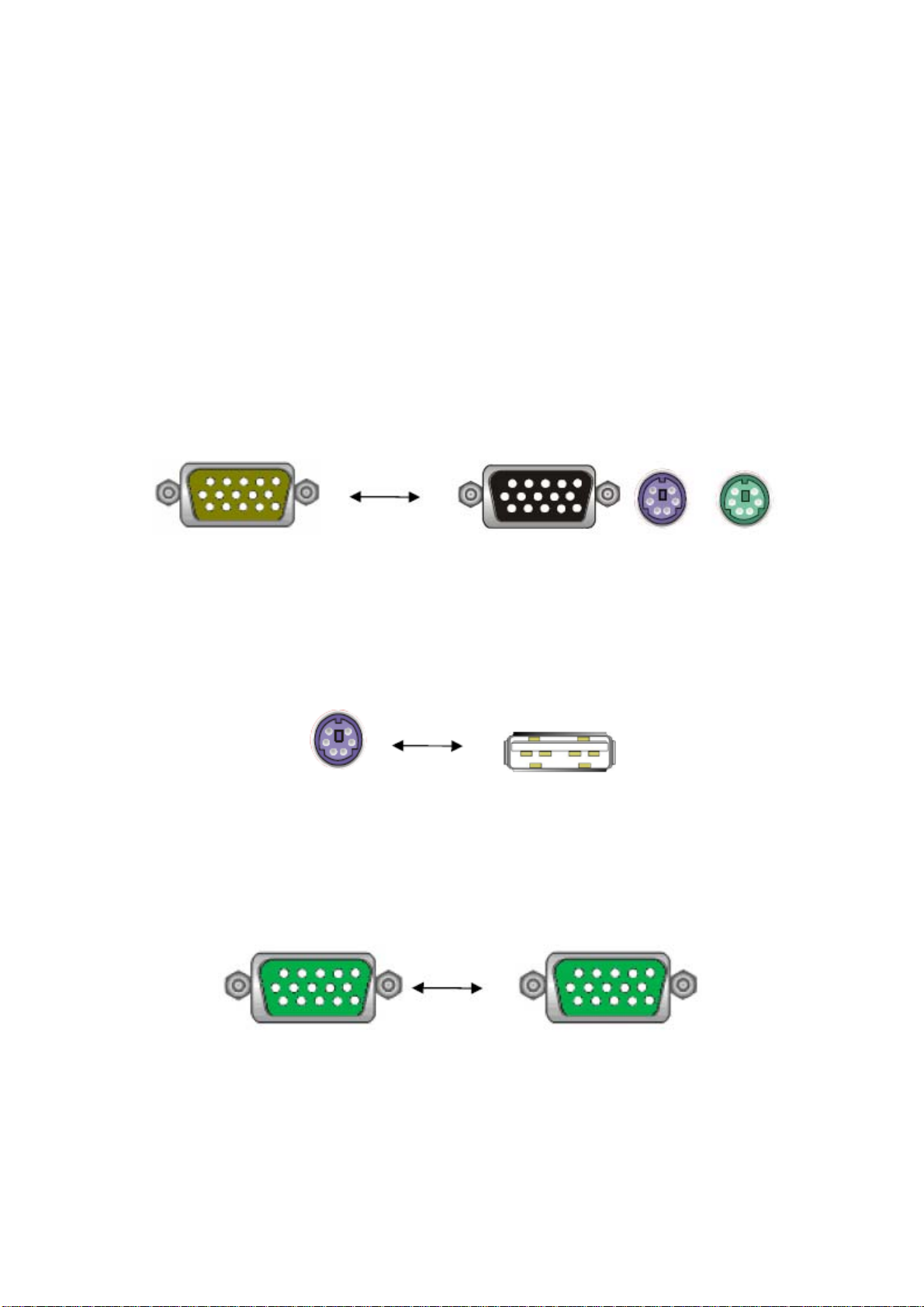
2.2 Cable Diagram
2.2.1 3-in-1 DB15 Cable
One end, HDDB15 (male) connectors with another end HDDB15 (male)/ two
PS/2 (mini-din 6-pin) connectors.
2.2.2 PS/2 (keyboard) to USB adapter
PS/2 (keyboard) to USB (keyboard and mouse) adapter.
2.2.3 Daisy Chain Cable
VGA Cable: HDDB15 Male to Male.
Daisy chain needs the cable all 15 lines connected. This is a special VGA cable, normal
VGA cable has unconnected lines. Do not use other VGA cable for daisy chain.
4
Page 9

2.3 Rack Mount Installation
Before installation, please make sure all of peripherals and computers have
been turned off. Find a convenient place to put your KVM Switch. The 19”
rack mount form factor makes it ideally mountable on a 19” rack. When
mounting to a rack, attach the included brackets to the sides of the KVM
Switch. Take note of the length of your cables so that your computers, KVM
Switch, keyboard, mouse and monitor are distanced properly.
The KVM Switch can also be placed on a desk with attached footpads. To
install footpads, please turn upside down and refer to the following
instructions properly for installing the footpads.
For PC with USB port, use a PS/2 to USB converter to switch between interfaces and
connect via PC’s USB slot.
5
Page 10

2.4 3-in-1 HDB15 Cable Installation
On the back of the KVM Switch, each of the 8 /16 PC ports has a HDB15 type
connector. Each cable that comes with the Switch has a 3-in-1 connector at
one end and a single HDB15 male connector at the other end. Plug the single
connector end of the cable into the KVM PC port, and then plug the other end
of cable to a PC VGA port.
PS/2 computer --- Plug in the PS/2 mouse connector to the computer mouse
port, then the PS/2 keyboard connector to computer keyboard port.
USB computer --- Install a PS/2-to-USB converter to the keyboard PS/2
connector, plug in USB connector to the PC USB port. This single USB port
can handle both keyboard and mouse data.
Note: The PS/2-to-USB converter is optional, please order C200K-C while
needed.
6
Page 11

2.5 Installation Steps
Follow the steps below to setup the hardware:
y Plug the 3-in-1 end of the KVM cable to the PC. Connect the HDB-15
connector to PC’s VGA port. Attached the PS/2 connector for both
mouse and keyboard to PC’s PS/2 ports.
y For PC with USB port, use a PS/2 to USB converter to switch
between interfaces and connect via PC’s USB slot.
y Then connect the other end of the 3-in-1 cable with only a single
HDB-15 connector to the PC port on the rear of KVM.
y Connecting multiple KVM together, please use a daisy chain cable
(sold separately) to connect via the Daisy Chain port and Local
Console’s VGA port.
y Double check whether all cables/connectors are properly connected.
Plug the power supply to the KVM switch and plug the AC power plug
7
Page 12

into the electrical receptacle. Now you will see the LED of Port 1 lights
up, and hear a beep sound.
y Recommended Power On sequence: Monitor, KVM then PC.
2.6 Daisy Chain Connection
Connecting multiple KVM together, please use a daisy chain cable (sold
separately) to connect via the Daisy Chain port and Local Console’s VGA port.
Use one end of daisy chain cable to connect to the Daisy Chain port of
Master KVM switch and connect the other end of daisy chain cable to the
Local Console port of the next Slave KVM switch. Please repeat the
connection procedures for next Slave KVM switch. Users can daisy chain up
to eight banks in maximum.
The console OSD menu will show only the port information of the master
KVM switch. When the master unit starts up, it will query all daisy chained
Slave units, and automatically set up the Bank ID for each Slave unit. So the
7-seg LED on the Master unit will display 1, Slave 1 will display 2, Slave 2 will
display 3, and so on. If not so, please reset (press “BANK” and port button)
the Master unit to update the Bank ID immediately. Hot Plug function is
supported in daisy chain connection. The Master unit will auto-query the daisy
chained Slaves every 30 seconds.
8
Page 13

Chapter 3 Operation
3.1 Push Button
Users can simply switch to a port by pressing the corresponding push button
on the LED. For 8 ports KVM Switch, please press button 1 ~ 8 directly to
select the port you want. For 16 ports KVM Switch, please press “Shift” button
and individual button 1~8 simultaneously to switch to the port from port 9 to
port 16. For example: Pressing “shift” button and 5 simultaneously to switch
to port 13, and the port red LED will turn on. After power on the KVM switch,
all of console ports will be linked to Computer port 1.
8-Port Front View
16-Port Front View
Press “BANK” button and the port button simultaneously will reset the KVM switch.
3.2 BANK 7-seg LED
When users want to view the next bank, please press “BANK” push button.
The bank LED will be changed from bank 1 to the maximum daisy chain level
and then to bank 1 again.
9
Page 14

3.3 Hot Plug
The KVM Switch supports “Hot Plug” function for any non-PS/2 connectors.
Users may Hot Plug the USB mouse or USB keyboard.
y DO NOT hot plug PS/2 port.
y Certain Operation Systems like SCO Unix or Linux does not support
“Hot Plug” function. If users apply “Hot Plug” to this kind of O.S., it will
cause unpredictable behavior or shut down the Computer. Before
attempting to use “Hot Plug”, please make sure Operation Systems
and mouse software driver support the “Hot Plug” function.
3.4 Hotkey
The KVM switch provides Hotkey feature for easy operation between
connected PC. The Hotkey feature can be utilized by pressing “Caps Lock”
and “Caps Lock” twice combining with other keys to initiate functions. Please
press the keys in consecutive orders within 2 seconds of each key.
3.4.1 Hotkey Example
1. To initiate OSD interface, please press the following keys consecutively
(For further information on operation of OSD interface, please consult the
User Manual):
2. To switch between banks and ports, press the following set of keys:
10
Page 15

¾ First digit refers to the bank numbers used for identifying each
KVM in multiple device connections. The last two digits represent
the port for each PC connected to the KVM switch.
3. The OSD interface can also be accessed via Mouse:
¾ Press and hold the left button of the mouse and hit the Esc key to
show the Status screen.
¾ Press and hold the right button of the mouse and hit the Esc key
to bring up the Main Menu.
3.4.2 Hotkey List
Command Description
For accessing OSD interface
Space Bar
↑ Switches to the previous port.
↓ Switches to the next port.
[1, 2, …, 8] Bank
[01, 02, …, 16] Port
Page Up Switches to previous bank.
Page Down Switches to next bank.
B Turns beep sound On/Off.
R
S
U
P
for further configuration
settings.
¾ First digit refers to the
bank number of the
KVM switch used in
multiple KVM connection
via Daisy Chain.
¾ The last two digits is the
port number used for
selecting between PCs.
Allows supervisor to reset the
device back to factory default.
Allows supervisor to activate
auto-scan function.
Allows Supervisor to activate
security function On/Off.
Log out of the device and
only valid when security
features is turned on.
3.5 OSD Menu
OSD (On Screen Display) Menu provides a menu-driven interface to control
the KVM switch.
11
Page 16

This OSD Menu has four types of display screens:
1. Login Window - When powering on this KVM switch, it will prompt a
login window and ask for user name and password. This KVM system can
setup one SUPERVISOR and eight USERS. SUPERVISOR can access
to all OSD functions. USER can access to PORT NAME and PORT
SEARCH only.
2. Status screen - After the logging in, the Status screen will show up to
display the current port settings and Hotkey type.
3. Port Name - This menu displays port status, and users can switch to
other port through this interface.
4. Main Menu - There are eight menus to operate. They are listed as follows:
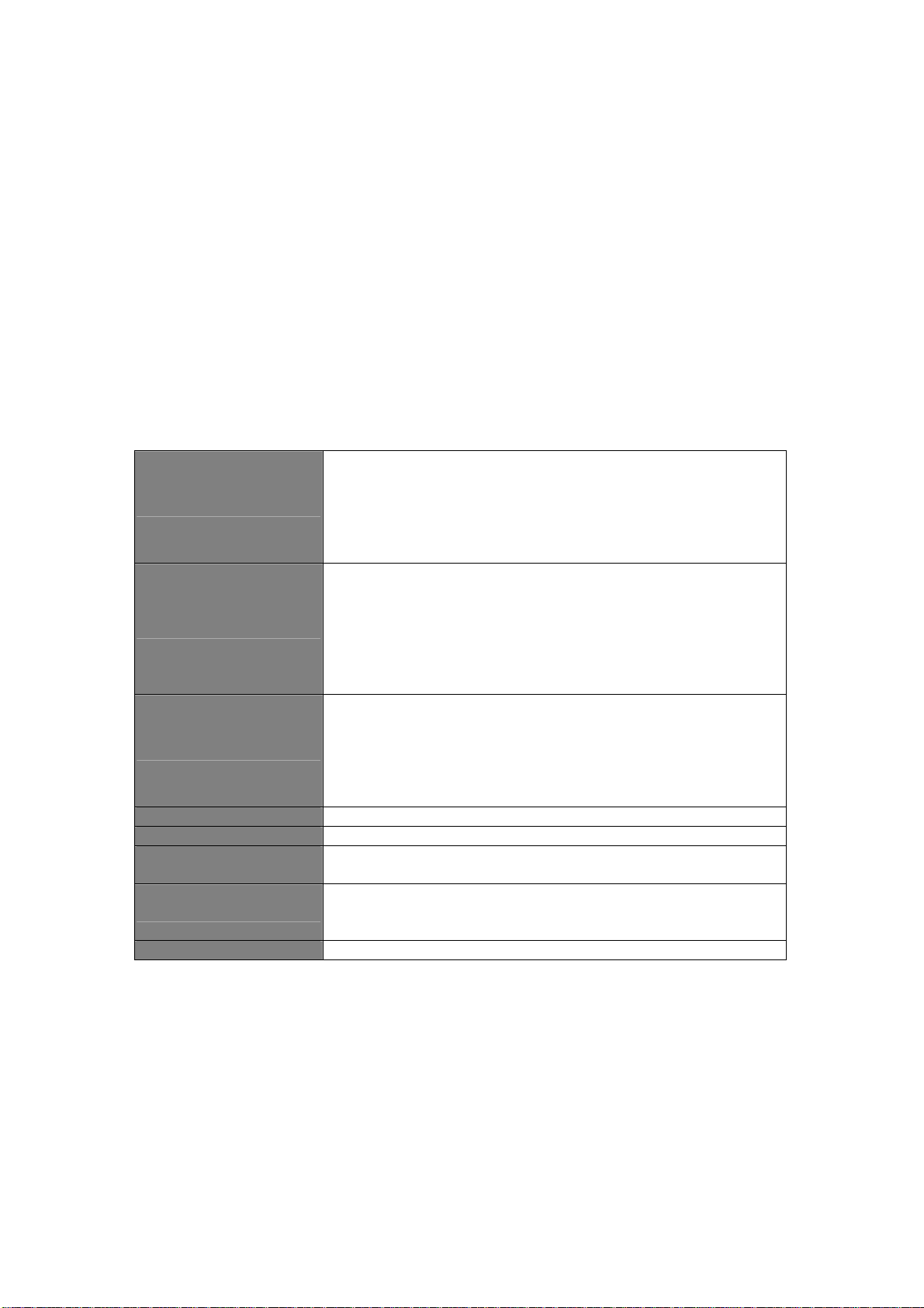
Parameter Description
01 LANGUAGE OSD language selection
02 PORT NAME EDIT PORT NAME modification
03 PORT SEARCH Quick searching by port name
04 USER SECURITY Change password
05 ACCESS LIST Define user access authority
06 HOTKEY Change Hotkey
07 TIME SETTINGS Modify auto-SCAN time interval
08 OSD MOUSE Modify OSD MOUSE speed
12
Page 17

3.5.1 Login Window
If the Security function is enabled (default is disabled), the Login window will
show up waiting for username and password when device powers on.
Parameter Default
SUPERVISOR
Username
SUPERVISOR
Password
These values are case-insensitive, while OSD display fixed in upper case.
After login or port switch by panel button, OSD or Hotkey, the Status screen
will show up to display the information of current settings. (Digit 1: BANK
NUMBER, Digit 2: PORT NUMBER, PORT NAME, and current Hotkey
settings. Pressing any key or moving mouse will let the Status screen
disappeared.)
00000000 (Eight Zeros)
00000000 (Eight Zeros)
Auto-LOGOUT function
y In Login window, if no input for username and password over 1 minute,
the screen will disappear. Hit any key to bring up the Login window
again.
y At normal operation, if no input from the console keyboard or mouse
over 10 minutes the KVM switch will turn off the screen display and
show up Login window asking for user name and password. One
more minute of keyboard/mouse inactivity, the monitor will be turned
off (Note the monitor LED turns from green color to orange color).
13
Page 18

3.5.2 Port Name
The first page shows the current port name, the selected port, and the
operation hint.
Command Description
F1 Go to the Main Menu.
Logouts of the OSD. If
Security is enabled it will
show up the Login window
F2
F3 Previous Menu
Enter Switch to the selected port
↑/↓
PgUp Previous Bank
PgDn Next Bank
Esc Exit
1 Show ports 01 ~ 08
2 Show ports 09 ~ 16
3 Show ports 17 ~ 24
4 Show ports 25 ~ 32
waiting for username and
password. If Security is
disabled it will show the
Status window.
Select the port (press Enter
to switch)
y The numeric keypad is not supported, while in OSD screen, the arrow
keys, PgUp, PgDn, and Enter keys are supported.
14
Page 19

3.5.3 Language
The OSD supports eight languages: English, French, German, Italian,
Spanish, Simplified Chinese, Japanese, and Russian. The default language is
ENGLISH. Moving the cursor by keyboard (Up Arrow key or the Down Arrow
key) or mouse to select the language you like.
3.5.4 PORT NAME EDIT
The first line bar is Bank number, following lines are port name list. Use
keyboard (Up Arrow key or Down Arrow key) or mouse to select the port.
After select the port, you can either press <Enter>, or move the cursor to port
name and double click left button of mouse to switch the port immediately.
Press PgUp key or PgDn key for selecting the previous or next Bank. Press
<Enter> key for editing port name. Press <Esc> key to cancel the editing
without any change or press <Enter> key to complete the editing.
15
Page 20

3.5.5 Port Search
Search the computer by port name. Enter “*” will show all the port names.
3.5.6 User Security
There are two types of user levels: SUPERVISOR and USER. There is one
SUPERVISOR and up to eight USERS can be configured. Press the <Enter>
key or right button of mouse for editing. The left-top “S” means SUPERVISOR,
and “1”, “2”, “3”,…., “8” means USERS. The maximum length of NAME and
PASSWORD is eight characters (A~Z and 0~9).
16
Page 21

3.5.7 Access List
Only SUPERVISOR can configure the ACCESS LIST. The first column is the
port number, following the server/computer name list. The last 8 columns are
the access right of each user. Use the <Enter> key or left button of mouse to
active/deactivate the access right of each port. “X” means to disable access
and “O” means to enable access.
3.5.8 Hotkey
Some keyboard may not equip with all the special keys. Make sure the key
select is available on the keyboard.
17
Page 22

3.5.9 Time Setting
When the Auto-Scan function is activated, the KVM switch will auto-scan the
host ports one by one according interval setting. Notice that the port without
connecting to a computer/server will be skipped on the scan. The interval
range is 5 ~ 99 seconds, and the default interval is 10 seconds. Press
<Enter> key to save the SCAN TIME setting.
3.5.10 OSD Mouse
Users can change the moving speed of mouse cursor in this item. There are
three levels to choose from. The fastest moving speed is FAST, the second is
MIDDLE and the slowest is SLOW. Using "
move highlight bar to the wished speed. Press the <Enter> key to go into
effect.
↑" and "↓" key on keyboard to
18
Page 23

Chapter 4 Troubleshooting
y No LED display
¾ Make sure the power adapter is correctly plugged into the KVM
Switch. If the LED’s still won’t light, perform soft reset to KVM
switch by pressing “BANK” button and last port button at the same
time.
¾ Do the hard reset by unplugging the power then plugging in again.
y The computer boot up fine, but keyboard doesn’t work
¾ PS/2 keyboard or PS/2 mouse port is not designed for Hot Plug.
USB mouse and keyboard can Hot Plug, but need to wait few
seconds for Computer bus emulations.
¾ Don’t press any keys on the keyboard while the selected
computer is booting up. Otherwise it might cause the keyboard
error or keyboard is not detected at Host side.
¾ Make sure the keyboard works when directly plugged into the
computer.
¾ Try a different keyboard, but use only 101, 102 or 104-key
keyboard.
y The Mouse is not detected during PC boot up
¾ Make sure to plug in mouse first, and then keyboard last.
¾ Make sure the USB or PS/2 mouse works when directly plugged
into the computer.
¾ Avoiding moving the mouse or pressing the mouse buttons when
switching ports.
y VGA resolution output mismatch with the monitor’s
¾ The KVM switch will provide DDC information to all the PC VGA
board. If both the local console’s monitor and KVM switch are
turned on before the PC boot up, or if the PC boot up faster then
the KVM switch, the PC miss the DDC (Data Display Channel)
19
Page 24

information that causes the VGA resolution output mismatch with
the monitor’s.
¾ In this case, please turn off the PC wait few minute then turn on
again.
y Micronet provide tech support
¾ You can find related information from web site
www.micronet.info.
¾ Any question about Micronet KVM product, please send mail to
support@micronet.info.
20
 Loading...