

Page 1
Installation Method
For optimum performance and long term operation it is advisable to
connect to the vessels 12/24Vdc supply rather than relying on small
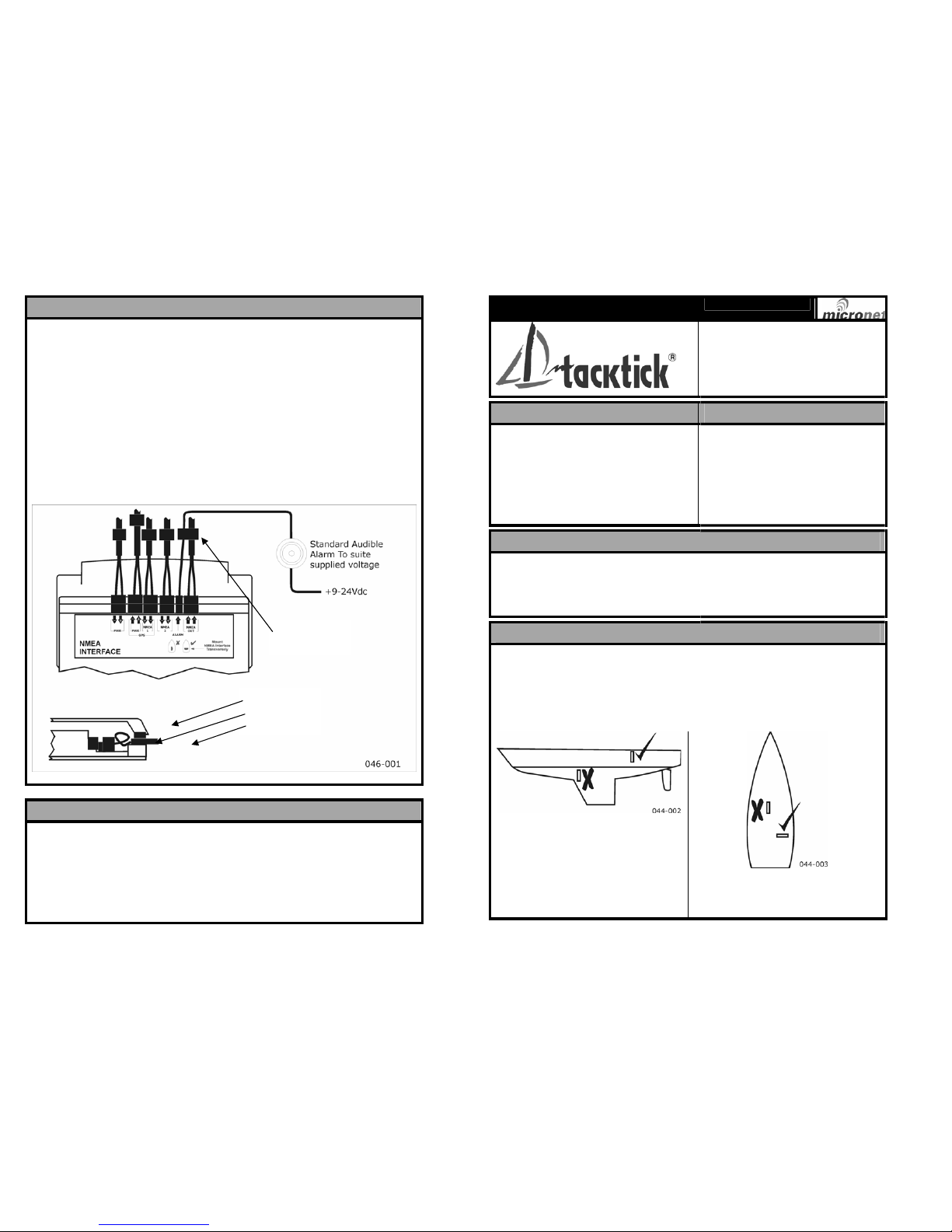
power cells. Connect the cable ends from the transducers and power
supply to the supplied connectors using the supplied screwdriver taking
care to ensure that all core colours are positioned correctly. It is advisable
to sheath the screens to prevent short circuit problems once the cover is
in place.
Insert the connectors into the appropriate sockets on the Hull Transmitter
and loop the single cores to allow the outer cable sheath to be secured in
the clamp when the cover is fitted.
Secure the cables close to the Hull Transmitter to reduce the possibility of
the connections becoming loose later.
NMEA Sentences (0183 V2.30)
Received Sentences: DPT, HDG, MWV, RMB, RMC, VHW
Transmitted Sentences: DPT, GLL, HDG, MTW, MWV, RMC, VHW, VLW
NOTE: Only information available will be transmitted.
NMEA Interface
Tacktick Limited
22 North Street, Emsworth,
Hampshire, PO10 7DG, England
Tel. +44 (0)1243 379331
Fax. +44 (0) 1243 379199
www.tacktick.com
Tools Required Parts List
1. 2mm or 5mm Drill Bit
2. Power Drill
3. Cross Head Screwdriver
1. Mounting Template
2. Mounting Bracket
3. Mounting Screws (3 off)
4. Mounting Bolts (3 off)
5. M4 Studs & Thumbnuts (3 off)
6. Double Sided Tape
Precautions
The NMEA Interface should be mounted in a dry area of the boat to
protect the cables and connectors from corrosion.
Cables should be supported close to the Hull Transmitter box to prevent
possible strain on the internal connectors.
All cables should be supported by clamps and ties close to the unit.
Positioning Advise
The NMEA Interface should be mounted such that the cables from the
transducers can be routed to it easily through the boat. Mounting the Hull
Transmitter close to the transducers will allow easy cable routing. Avoid
mounting on metallic surfaces or where there are metallic objects between
the Interface Box and other Micronet instruments.
Avoid bilge areas if possible to
protect the equipment and
connections
For optimum signal avoid mounting
the transmitter on a longitudinal
surface
uu046 rev. 7
Cover
Cable Loop
Cable Clamp
Cable
Clamps
Page 2
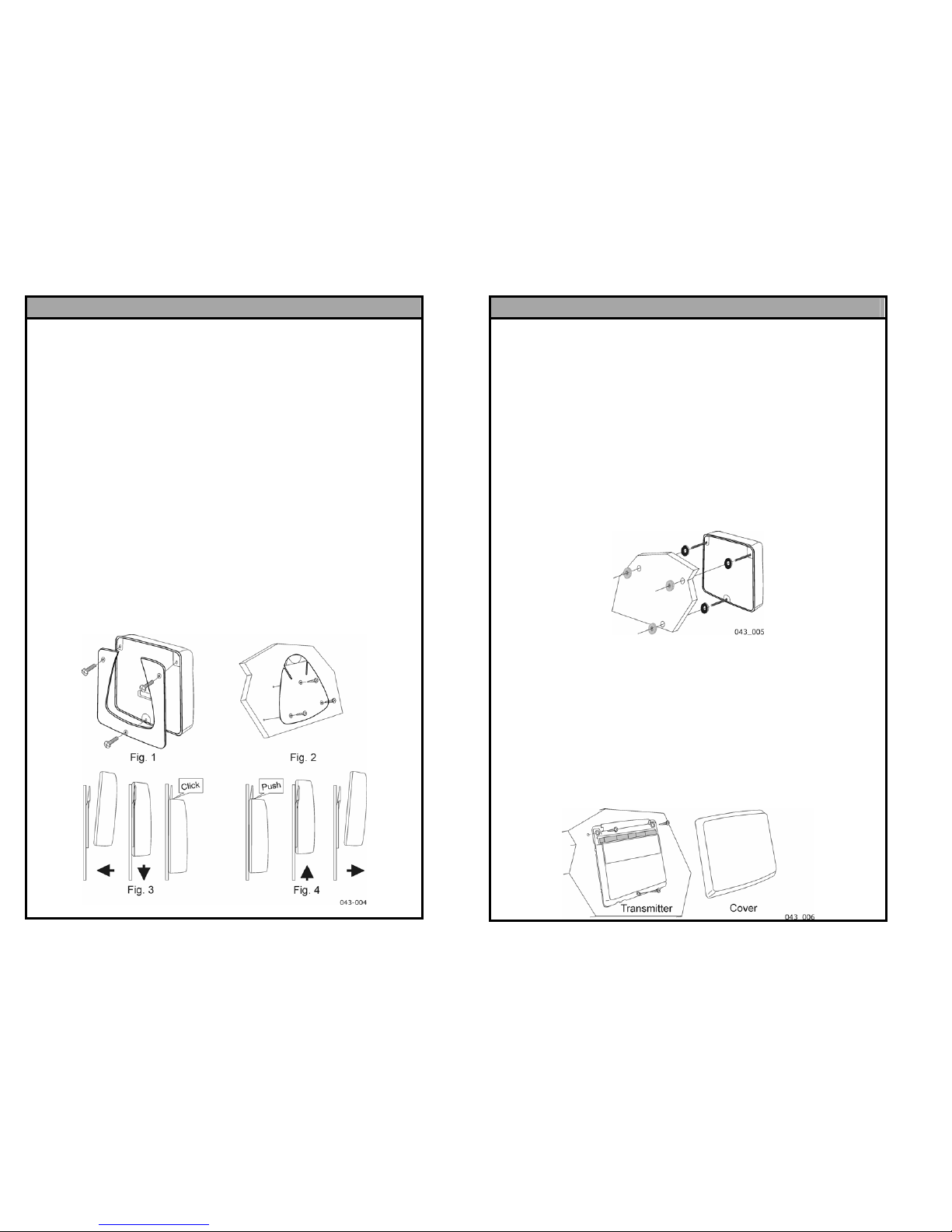
Bracket Mounting
This method allows for the easy removal of a NMEA Interface as
and when required for either security reasons or to prevent
damage whilst not in use.
1. Using the three supplied M4 bolts attach the back plate to the rear of
the NMEA Interface. (Fig. 1)
2. Drill three 3mm holes marked “BRACKET” on the Template and using
the supplied screws attach the clip bracket to the mounting surface.
(Fig. 2)
3. Place the NMEA Interface flat against the bracket slightly higher than
the final position and slide gently down into position. There will be a
small click as the bracket secures the Interface in position. (Fig. 3)
4. Connect and secure the cables leaving a loop of single core cable
inside the casing before fitting the cover such that the outer sheath is
secured beneath the rubber clamp. Once the Interface is secured in
position it is advisable to clamp the cables to the mounting surface
close to the Interface.
5. To release the NMEA Int erface press lightly on the bracket tab and
slide the Transmitter up until it can be pulled away from the surface.
(Fig. 4)
Note: Take care to disconnect cables carefully before removing the unit
and ensure that the cables and connectors left behind are protected
from both water and physical damage.
Surface Mounting
With Rear Access
Position the supplied Template carefully before starting.
1. Drill three 5mm holes marked “B” on the Template.
2. Screw the four M4 brass studs into the rear of the Interface.
3. Place the Interface in positi on pushing the three studs through the
newly drilled holes.
4. Using the 3 supplied Thumb Nuts secure the Interface to the surface
making sure it is level before fully tightening.
5. Connect and secure the cables leaving a loop of single core cable
inside the casing before fitting the cover such that the outer sheath is
secured beneath the rubber clamp. Once the Interface is secured in
position it is advisable to clamp the cables to the mounting surface
close to the Interface.
Without Rear Access
Position the supplied Template carefully before starting.
1. Drill three 2mm holes marked “SURFACE” on the Template
2. Remove the cover of the Interface from the main body.
4. A the Interface to the mounting surface using the three self tapping
screws provided. Take care not to over tighten the screws as this
may cause the moulding to crack.
5. Connect and secure the cables as shown overleaf.
6. Carefully fit the cover securing the cables with the clamp bar.
 Loading...