

MicroNet RAIDBANK 5 Owner's Manual
Storage you can rely on
Owner’s Guide
Storage you can rely on
September 2010
www.MicroNet.com

Welcome
Welcome From MicroNet Technology
We are pleased that you have chosen the RAIDBank5. Our systems are designed
for speed, reliability, compatibility, and performance. We think you will find the
system easy to install, and a productive addition to your computer system.
This manual presumes that you are familiar with standard computer operations;
this includes copying files, opening documents, clicking with the mouse, and
organizing files or folders within other folders. If you are unfamiliar with
these operations, please consult the User’s Guide that was supplied with your
computer system. Your computer dealer and local user’s groups are also good
sources of information. After you are comfortable with the operation of your
computer, continue reading this manual which describes hardware installation
and operation.
Your comments assist us in improving and updating our products. Please feel
free to share them with us. Please send comments to:
MicroNet Technology
Attn: Customer Service
20525 Manhattan Place
Torrance, CA 90501
info@micronet.com
RAIDBank5 Owner’s Manual
2

Table of Contents
Table of Contents
Welcome Note
Table of Contents
Warranty Information
Technical Support Policies
Chapter 1. Getting Started
Features and Benefits
System Requirements and Compatibility
Unpacking the RAIDBank5
What’s Included
Choosing a place for your RAIDBank5
Installing the Fan Module
The RAIDBank5 Interface Components
Communications and Control
Hot Plug Drive Replacement
Connecting the RAIDBank5
Installing the included host bus adapter
RAID System Management Control Methods
Chapter 2. Understanding RAID
RAID
RAID 0
Spanned RAID
RAID 1
RAID 10
RAID 3
RAID 5
Direct Disk Mapping
Hot Swappable Disk Support
Hot Spare Drives
Hot Swap Disk Rebuild
Chapter 3. RAID Controls-LCD Interface
Conventions
Access Procedure
1. Quick Volume/RAID Setup
2. Disk Management Functions
3. RAID Function Control
4. System Functions
Chapter 4. RAID Management Software
1. Installation
2. The User Interface
3. Basic Mode
3.1 RAID and Disk Info
3.2 Event Log
3.3 RAID Configuration
3.4 Button Backup Settings
4. Advanced Mode
4.1 Remote Notification Settings
4.2 Advanced RAID Configuration
4.3 Firmware Control
4.4 RAID Standby and Rebuild Priority Settings
4.5 Encryption Management
2
3
4
5
7
7
7
7
8
8
8
9
10
10
11
12
12
14
14
15
15
15
16
16
16
17
17
17
17
18
18
18
18
19
19
20
21
21
21
22
22
22
23
24
24
24
25
26
26
27
RAIDBank5 Owner’s Manual
3

Table of Contents
Chapter 5. Host Computer Setup
1. Volume Setup and Apple Macintosh
2. Volume Setup on Microsoft Windows XP/2003
3. Volume Setup on Microsoft Windows Vista/7/2008
4. Optimizing Windows Caching Policy
5. Safe Volume Dismounting
Chapter 6. Troubleshooting
Daily Use Tips
General Use Precautions
Frequently Asked Questions
General
Mac and Mac OS Specific
Windows Specific
Appendix A. Getting Help
Appendix B. RAID Level Comparison Table
Appendix C. Glossary of RAID Terms
Appendix D. Product Specifications
FCC Compliance Statement
29
29
30
31
32
32
33
33
33
34
34
34
35
37
38
39
46
47
RAIDBank5 Owner’s Manual
4

Warranty
Two Year Limited Warranty
Micronet warrants this product (the “Product”) against defects in material or workmanship as follows:
1. LABOR: For a period of two (2) year from the original date of purchase from Micronet or its authorized
reseller, Micronet will repair defective Product (or, at its option, replace with a new or recertified product) at no
charge. After this 2 year period, you must pay for all labor charges.
2. PARTS: For a period of two (2) year from the original date of purchase from Micronet or its authorized
reseller, Micronet will supply, at no charge, new or rebuilt replacement parts in exchange for defective parts
of this Product. Any replacement parts will be warranted for the remainder of the original warranty period or
ninety (90) days from installation by Micronet. All exchanged parts replaced under this warranty will become
the property of Micronet.
This warranty only covers the hardware components packaged with the Product. This warranty does not cover
any software contained in, or included with, the Product; any such software is provided “AS IS”. Please refer
to any documentation included with the software for your rights and obligations with respect to the software.
This warranty extends only to you, the original purchaser. It is not transferable to any one who subsequently
purchases the Product from you.
Proof of purchase in the form of a bill of sale (which is evidence that the Product is within the warranty period)
must be presented to obtain warranty service.
To obtain warranty service you must take the Product, or deliver the Product freight prepaid, in either it’s
original packaging, or in a package that provides the Product with a degree of protection equivalent to that of
the original packaging, to Micronet. Please contact Micronet at the number listed on the reverse side for further
information.
Micronet is not responsible for any damage to, or loss of, any programs, data, or other information stored on any
media or any part of any Product serviced hereunder. Be sure to remove all features, parts, options, alterations,
and attachments not under warranty prior to returning the Product to Micronet. Micronet is not liable for any
loss or damage to these items.
This limited warranty does not cover: (1) any consumables (such as batteries) supplied with this product;
cosmetic damages; damage or loss to any software programs, data or removable storage media; or damage
due to the Product such as but not limited to excessive heat or humidity, or modifications of this Product; (2)
improper installation, operation, testing or maintenance of this Product; (3) power failure or connection to
improper voltage supply; or; (4) attempted repair by any party other than Micronet. This Warranty does not apply
when the malfunction results from the use of this Product in conjunction with accessories, products or ancillary
or peripheral equipment, or where it is determined by Micronet that there is no fault with this Product itself. This
Limited Warranty is invalid if the factory applied serial number has been altered or removed from the Product.
Repair or replacement as provided under this warranty is the exclusive remedy of the consumer. Micronet shall
not be liable for any incidental or consequential damages for breach of any express or implied warranty, breach
of contract, negligence, strict liability or any other legal theory related to this product. Such damage include, but
are not limited to, loss of profit, loss of data, loss of use of the product or any associated equipment, down time
and purchaser’s time. Except to the extend prohibited by applicable law, any implied warranty of merchantability
or fitness for a particular purpose on this product is limited in duration of this warranty.
Some states do not allow the exclusion or limitation of incidental or consequential damages, or allow limitations
on how long on implied warranty lasts, so the above limitation or exclusions may not apply to you. This warranty
gives you specific rights; you may have other rights which vary from state to state.
RAIDBank5 Owner’s Manual
5

Warranty
Limitations of Liability
MicroNet Technology has tested the hardware described in this manual and reviewed its
contents. In no event will MicroNet or its resellers be liable for direct, indirect, incidental, or
consequential damage resulting from any defect in the hardware or manual, even if they have
been advised of the possibility of such damages. In particular, they shall have no liability
for any program or data stored in or used with MicroNet products, including the costs of
recovering or reproducing these programs or data.
During the specified warranty period, MicroNet guarantees that the product will perform
according to specifications determined by the manufacturer, and will be free of defects. Parts
and labor of the received product, and replacement parts and labor are guaranteed during
the specified warranty period. The warranty covers defects encountered in normal use of the
product, and does not apply when damage occurs due to improper use, abuse, mishandling,
accidents, sand, dirt, excessive dust, water damage, or unauthorized service. The product must
be packed in its original packing material when shipped, or the warranty will be void. In all
cases, proof of purchase must be presented when a warranty claim is being made.
This manual is copyrighted by MicroNet Technology. All rights are reserved. This documentation
may not, in whole or part, be copied, photocopied, reproduced, translated, or reduced to any
electronic medium or machine readable form without prior consent in writing from MicroNet.
MicroNet and the MicroNet logo are registered trademarks of MicroNet Technology. Microsoft
Windows and the Windows Logo are registered trademarks of Microsoft Corporation. All other
trademarks are the property of their respective owners.
Technical Support Policy
If you have a problem installing your system or suspect it is malfunctioning, please contact
the Authorized MicroNet Reseller from whom you purchased the system. If the reseller fails
to resolve the problem, please visit our support page at
or call MicroNet’s Help Desk for assistance at (310) 320-0772. Please have the model, serial
number, date of purchase, and the reseller’s name available before calling. If possible, call
from a telephone near the system so we can more readily direct you to make any necessary
system corrections, should they be required.
Returning Materials
www.micronet.com/support,
If a reseller or MicroNet Technician finds it necessary to have the system returned for testing
or servicing, a Return Materials Authorization (RMA) number will be issued. The RMA number
must be placed on the outside of the carton in large, visible letters near the address label.
Return the complete system including all cables and software. The system must be packed
in the original packing materials and shipped prepaid. MicroNet will repair the system and
return it prepaid by similar common carrier and priority. Please record the RMA number and
make reference to it when inquiring on the status of the system. A returned unit found to be
fault-free will carry a $65.00 charge for service and repackaging.
RAIDBank5 Owner’s Manual
6

1-Getting Started
Chapter 1. Getting Started
Thank you for purchasing The MicroNet RAIDBank5 storage solution. With speed, high
capacity, ease of use, and support for numerous applications, RAIDBank5 is the ideal solution
for all of your data storage needs.
Please take advantage of the information contained within this manual to ensure easy setup
and configuration. If at any time you require technical assistance, MicroNet’s Help Desk is
available at 310-320-0772 or at www.micronet.com/support
Features and Benefits
The RAIDBank5 Subsystem is a high-performance RAIDBank5 built around a powerful 64bit
controller designed to meet or exceed the highest industry standards. Outstanding features
include:
• SuperSpeed USB 3.0 (Compatible with USB 2.0), eSATA-300, FireWire 800, and FireWire
400 host connections for maximum host flexibility
• SATA II, NCQ enabled drive channels
• Configurable RAID engine for optimal performance and fault tolerance
Featuring high performance and availability RAID technology and advanced array management
features, The RAIDBank5 can serve in several applications:
• As a high speed local storage device for a dedicated workstation
• As a high-speed, fault tolerant server-attached storage device
• As a redundant backup station
System Requirements and Compatibility
The RAIDBank5 features USB 3.0 (Compatible with USB 2.0), eSATA-300, FireWire 800, and
FireWire 400 host connections, providing nearly universal connectivity. While the RAIDBank5
can function with a variety of hardware and software combination, MicroNet has tested and
approved the RAIDBank5 for compatibility with the following architectures:
Apple Hosts: G5/Intel Macintosh computers, OS 10.5 and newer
Windows Hosts: Pentium 4-2.8Ghz and newer, Windows revisions XP SP3 and newer
Note: At the time of publication no
Mac OS X drivers are available for
USB 3.0. USB 2.0 is fully supported
Unpacking the RAIDBank5
Please unpack your RAIDBank5 in a static free environment, carefully making sure not to
damage or discard any of the packing material. If the RAIDBank5 appears damaged, or if
any items of the contents listed below are missing or damaged, please contact your dealer or
distributor immediately.
In the unlikely event you may need to return the RAIDBank5 for repair or upgrade, please
use the original packing material to ensure safe transport.
RAIDBank5 Owner’s Manual
7
What’s Included
Your RAIDBank5 comes with the following items:
1x RAIDBank5 unit
5x Disk Drive Modules
1x SATA to eSATA cable Kit
1x eSATA to eSATA cable
1x USB3.0 Type A to B cable
1x 1394a to 1394a cable
1x 1394b to 1394b cable
1x Fan Module
1x User’s Manual and software CD
1x Power Cord
1x Quick Installation Guide
Choosing a location for your RAIDBank5
1-Getting Started
When selecting a place to set up your RAIDBank5, be sure to follow these guidelines:
• Place on a flat and stable surface capable of supporting at least 25lbs
• Place the RAIDBank5 close enough to the computer for the host connection cable to reach.
• Use a grounded wall outlet
• Avoid an electrical outlet controlled by wall switches or automatic timers. Accidental disruption
of the power source may wipe out data in the memory of your computer or RAIDBank5
• Keep the entire system away from potential sources of electromagnetic interference, such
as loudspeakers, cordless telephones, etc
CAUTION! Avoid direct sunlight, excessive heat, moisture, shock and
vibration, or dust
!
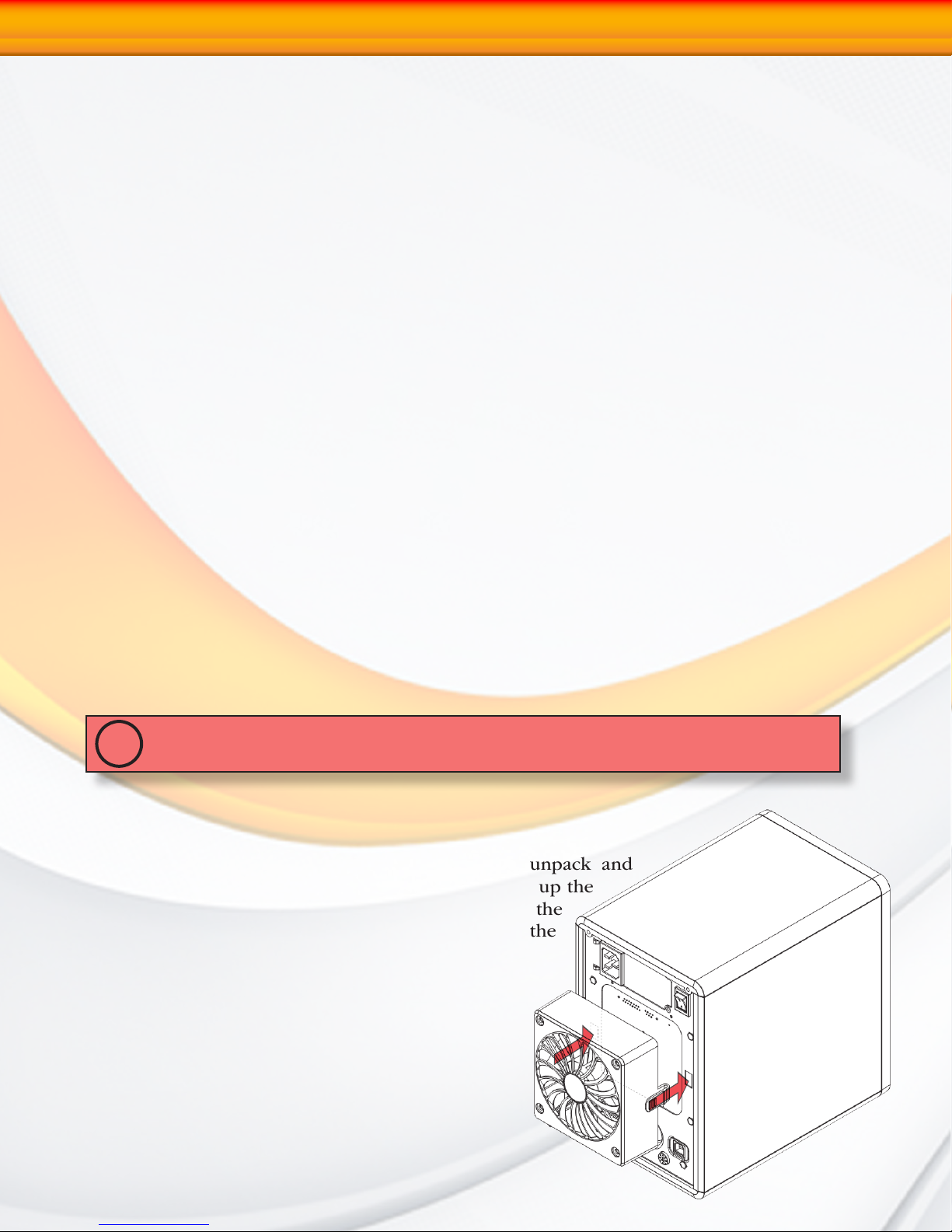
Installing the Fan Module
Before turning on the RAIDBank5, make sure to unpack and
install the fan module as illustrated right. Simply line up the
fan with the power connector (bottom edge) and the
securing clip slots (left and right,) and gently push the
fan evenly until the securing clips click into place.
RAIDBank5 Owner’s Manual
8
1-Getting Started
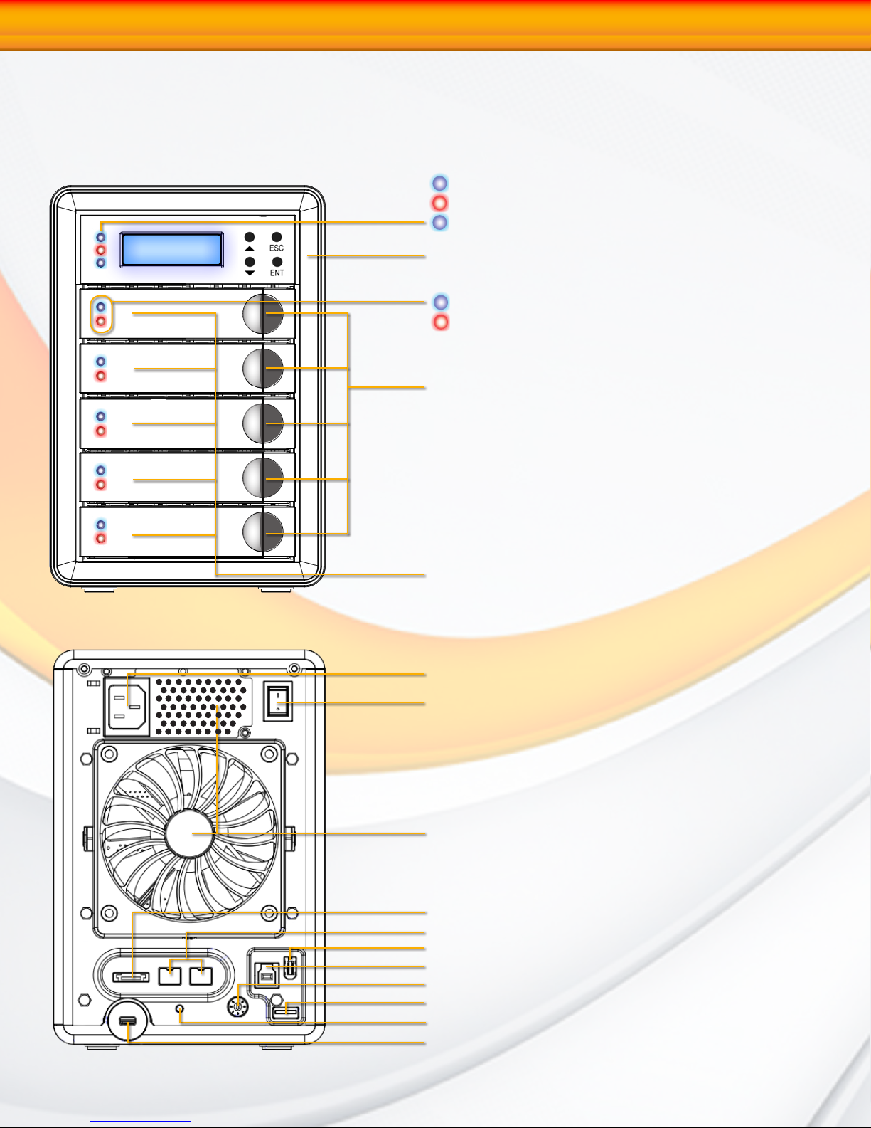
The RAIDBank5 interface components
The following figures illustrate the connector locations for the RAIDBank5.
FRONT VIEW
Power Indicator
Fault Indicator
Host activity Indicator
Front Display and control keypad
Disk Activity LED
Disk Power LED
Canister Release Latch
REAR VIEW
Disk Canisters
AC Power Connector
Master Power Switch
Fan vents (DO NOT BLOCK!)
Host eSATA Port
Host FireWire 800 Ports
Host FireWire 400 Port
Host USB 3.0 Port
Operating Mode Selector Switch
Encryption Key Slot
Settings/Mute/Backup Button
Security Lock Slot
RAIDBank5 Owner’s Manual
9
1-Getting Started
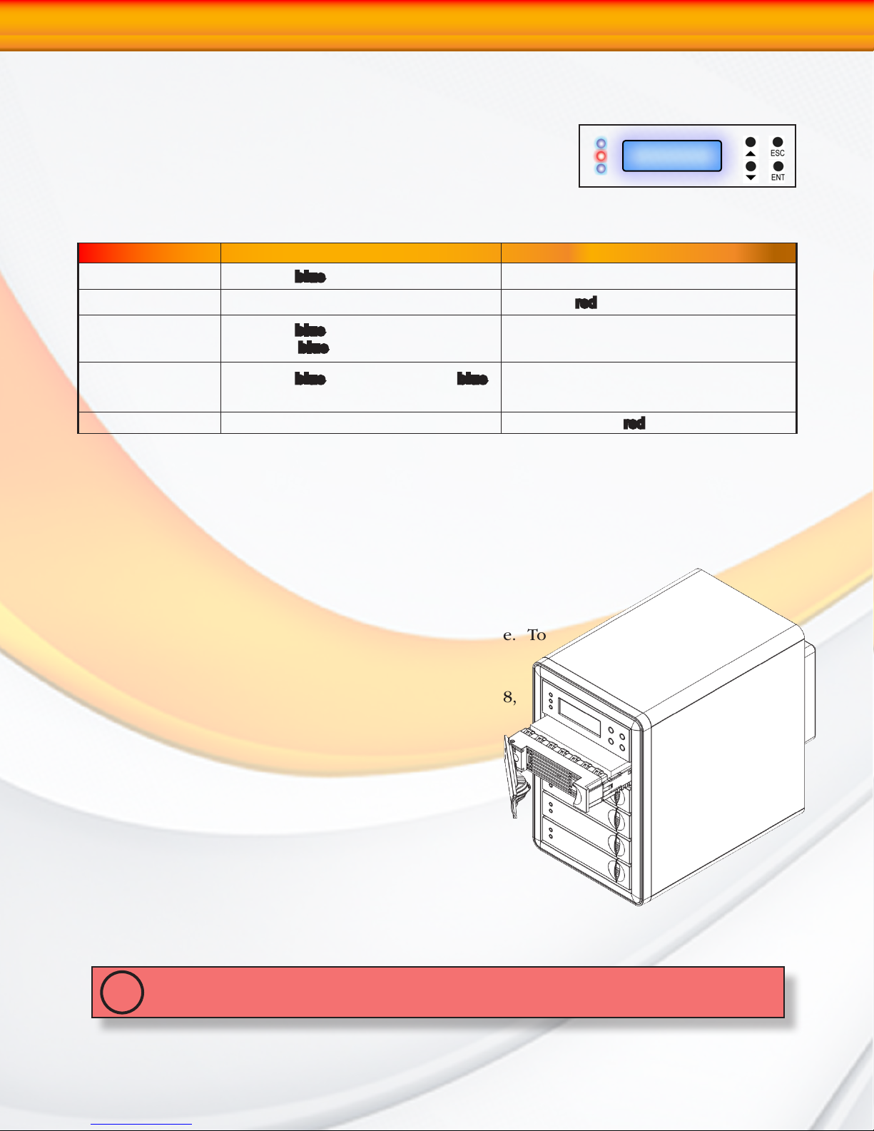
Communication and Control
RAID functions including creation, modification, and monitoring
can be accomplished through the LCD Control panel or the web
based administration user interface. The LCD status panel informs
you of the RAIDBank5’s current operating status at a glance, as
shown here:
Indicator Normal Status Problem Indication
Power LED (Front) LED glows blue Dark on power fault.
Fault LED LED is dark LED glows
Host Activity LED
Disk Activity LED
Disk Fault LED LED is dark This LED will blink
LED glows
host; blinks
LED glows
during hard drive read and write activity
blue when system links to a
blue when data is accessed.
blue on power on; blinks blue
N/A
N/A
red
red on disk fault.
Hot plug Drive Replacement
In the event of a drive failure, the RAIDBank5 supports the ability to hot-swap drives without
powering down the system. A data module can be removed and replaced without powering
off the unit or taking the system off line. In a fault tolerant array, the RAID rebu ildi ng
will proceed automatically in the background (see Section 2.Understanding
RAID for more information.)
The disk fault light will illuminate red upon disk failure. To
replace a drive, please follow these steps:
1. Press down on the drive release latch (see page 8,
“The RAIDBank5 Interface components”) to release
the drive tray
2. Gently pull out the disk drive tray handle and slide
out the drive tray.
3. To replace: Slide in the replacement drive module with
the tray handle open. When the tray is slid all the way
into the RAIDBank5, push the tray handle closed.
IMPORTANT: NEVER remove a drive tray without replacing it. Operating the RAID with a drive
tray missing will disrupt airflow and may cause the RAIDBank5 to fail.
!
RAIDBank5 Owner’s Manual
10

USB
HIGH SPEED
e
1-Getting Started
Connecting the RAIDBank5
Connecting the RAIDBank5 requires an available power socket, an operating system capable
of addressing volumes larger then 2TB, and a host with one of the following interfaces:
• An available USB 3.0 or 2.0 port
• An external SATA host bus connector with large LUN and port multiplier support
• An available FireWire 800 or FireWire 400 port
IMPORTANT: The RAIDBank5 can only use one connection at a time. Host plugs are shaped so
they can only be properly inserted one way; be sure to insert the plugs properly or you may
!
damage the system and void the warranty.
1. Plug the AC adapter cord into the power port on the back of the drive. The plug should
not require much effort to insert. If the plug will not go in, do not force it; the plug is
probably upside down. Rotate the plug and try again. Incorrectly inserting the plug
could damage the drive and void the warranty.
2. Plug the power cord into the power socket
3. Connect the appropriate cable to your host.
(USB) Connect the square USB 3.0
connector (type B) of the included USB
3.0 cable to a the square USB plug on the
RAIDBank5 (illustrated right in blue), and the
rectangular end to a free USB port on your
computer. The USB 3.0 ports are backwards
compatible with USB 2.0.
SATA
(eSATA) Connect the included eSATA
cable to a free eSATA port on your computer
(illustrated right in green.) If your computer
does not have eSATA ports, you may purchase
an eSATA expansion card for your computer.
Contact your authorized MicroNet reseller for further details.
Note: The RAIDBank5 requires an eSATA host connection with the following features:
• Port Multiplier Support
• Large LUN Support
• AHCI Mode Enabled and Active
Please consult your eSATA host bus manufacturer for more information.
(FireWire 400) Connect the FireWire 400 connector of the included FireWire cable to
a FireWire 400 port on the RAIDBank5, and the other end to a FireWire port on your
computer (illustrated in red).
(FireWire 800) Connect the FireWire
800 connector of the included FireWire
Note: All three FireWire ports are members of
the same bus. You may daisy chain additional
FireWire devices from a single host connection.
800 cable to a FireWire 800 port on the
RAIDBank5, and the other end to a FireWire port on your computer (illustrated in yellow).
4. Flip the power switch located on the back of the RAIDBank5 to the “ON” position
(labelled “-”.)
RAIDBank5 Owner’s Manual
11
1-Getting Started
Installing the Included host bus adapter
1. Turn your computer off and any peripherals connected to the computer (ie. printers,
external hard drives, etc.). Unplug the power cable from the rear of the power supply on
the back of the computer.
2. Remove the cover or door to access your computer’s expansion slots. For more information
on how to access your computer’s expansion slots consult your computer’s user manual.
3. Locate an open PCI Express slot and remove the metal cover plate on the rear of the
computer case (1X ~ 16X lane slots supported).
4. Insert the card into the open PCI Express slot and fasten the bracket to the rear of the case,
per your computer’s documentation.
5. Connect an LP4 molex power connector from the computer’s power supply to the LP4
connector on the card.
6. Replace your computer cover and reconnect power.
7. Power on your computer. Windows machines should automatically identify the new
hardware and install drivers. If driver installation is not successful, insert the provided
Driver CD into the computer’s CD/DVD drive. Autorun should start the installation program,
(If Autorun does not start, Go into “My Computer” and access the CD/DVD drive that the
CD is in, and run the “setup.exe” file located on the CD.) Follow the instructions onscreen
to complete the driver installation.
RAID System Management Controls
Note:
At the time of publication no Mac OS X
drivers are available for USB 3.0
Following the hardware installation, the RAIDBank5 must be configured and the volume
set units initialized before they are ready to use. This can be accomplished by one of the
following methods:
• RAID Mode Selector Switch
• Front panel touch-control keypad
• RAIDBank management Software
These user interfaces can access the built-in configuration and administration functions that
reside in the controller’s firmware. Advanced features such as multiple volume support, remote
notification, firmware updates, etc are accessible via the RAIDBank Management software.
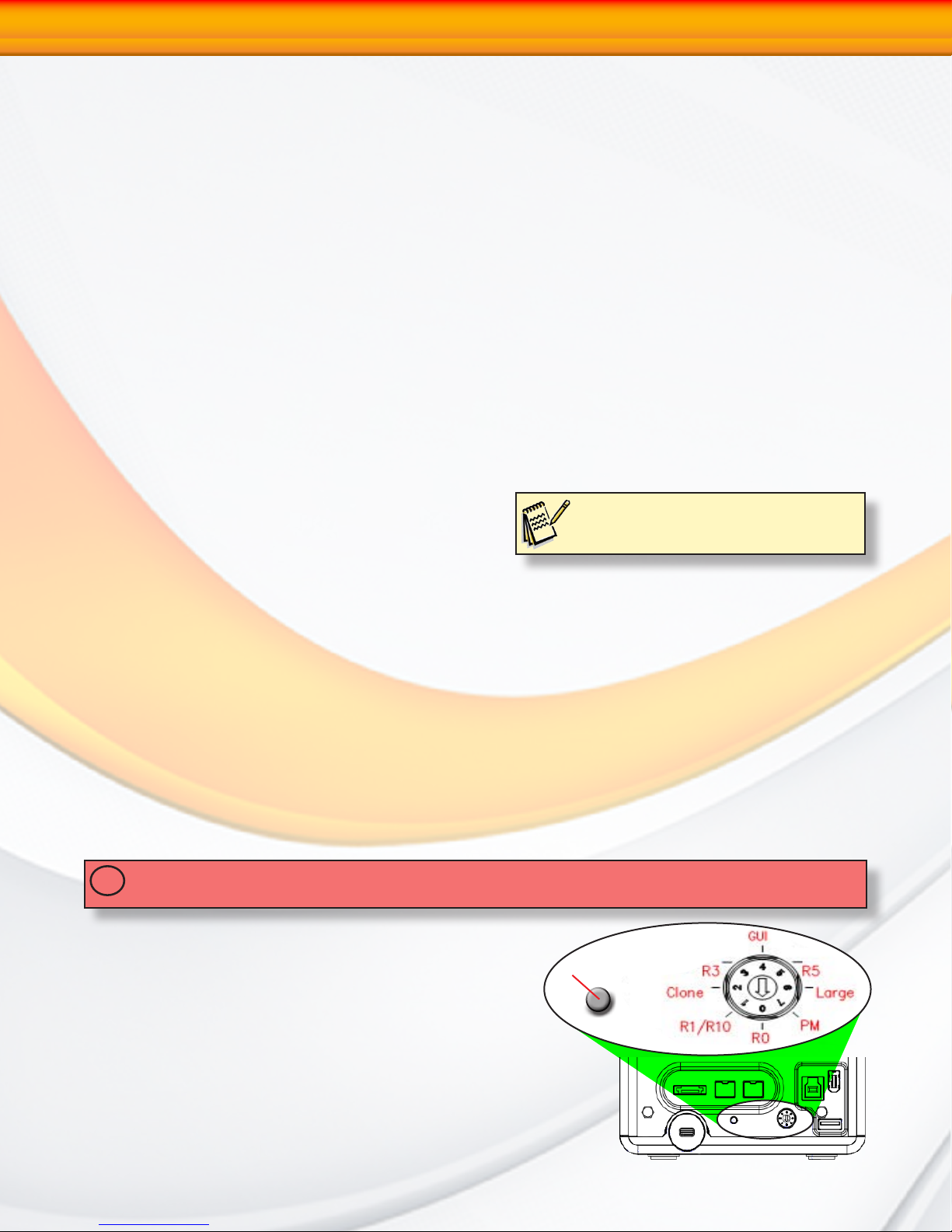
Configuration via RAID Mode Selector Switch
IMPORTANT: Changing the mode of operation will destroy all existing data! Please use care when
!
changing operating modes!
There are 7 Modes of operation addressable by the
rotary switch, listed as follows:
• Stripe (RAID 0)- Position 0
• Mirror (RAID 10)- Position 1
• Cloned Mirror (RAID 1)- Position 2
• RAID 3 (Fixed Parity)- Position 3
• Graphic User Interface (GUI) Control- Position 4
• RAID 5 (Distributed Parity)- Position 5
• Large Mode (Span)- Position 6
• Port Multiplier ( JBOD)- Position 7
Settings/mute/backup
RAIDBank5 Owner’s Manual
12
1-Getting Started
To set or change a RAID operating mode please follow the procedure herein:
1. Turn off the RAIDBank5
2. Use a small flathead screwdriver to turn the rotary mode selector switch to the operating
mode desired.
3. Press and hold the multifunction button “setting/mute/backup” button illustrated above and
power on the RAIDBank5. Release the button about 5 seconds after power on.
The RAIDBank5 will utilize all available hard drives to create a single RAID volume. For
more information regarding RAID technology and operating modes, please see Chapter 2:
Understanding RAID.
Using the front panel touch-control keypad
The Micronet RAIDBank5 has a front panel keypad and liquid crystal display (LCD) that
may be used for system configuration. The LCD provides a system of screens with areas for
information, status indication, or menus. The LCD screen displays up to two lines at a time of
menu items or other information.
The four function keys at the button of the front panel perform the following functions:
Key Function
Up Arrow
Down Arrow
ENT Key
ESC Key
The main menu can be activated by hitting the ENT key. Use the up and down arrow buttons to highlight a menu item. Press ENT to select the highlighted item. Press the UP/
DOWN to browse the selection. Press ESC to return to the previous screen. Refer to Chapter
4: RAIDBank5 Front Panel for more information.
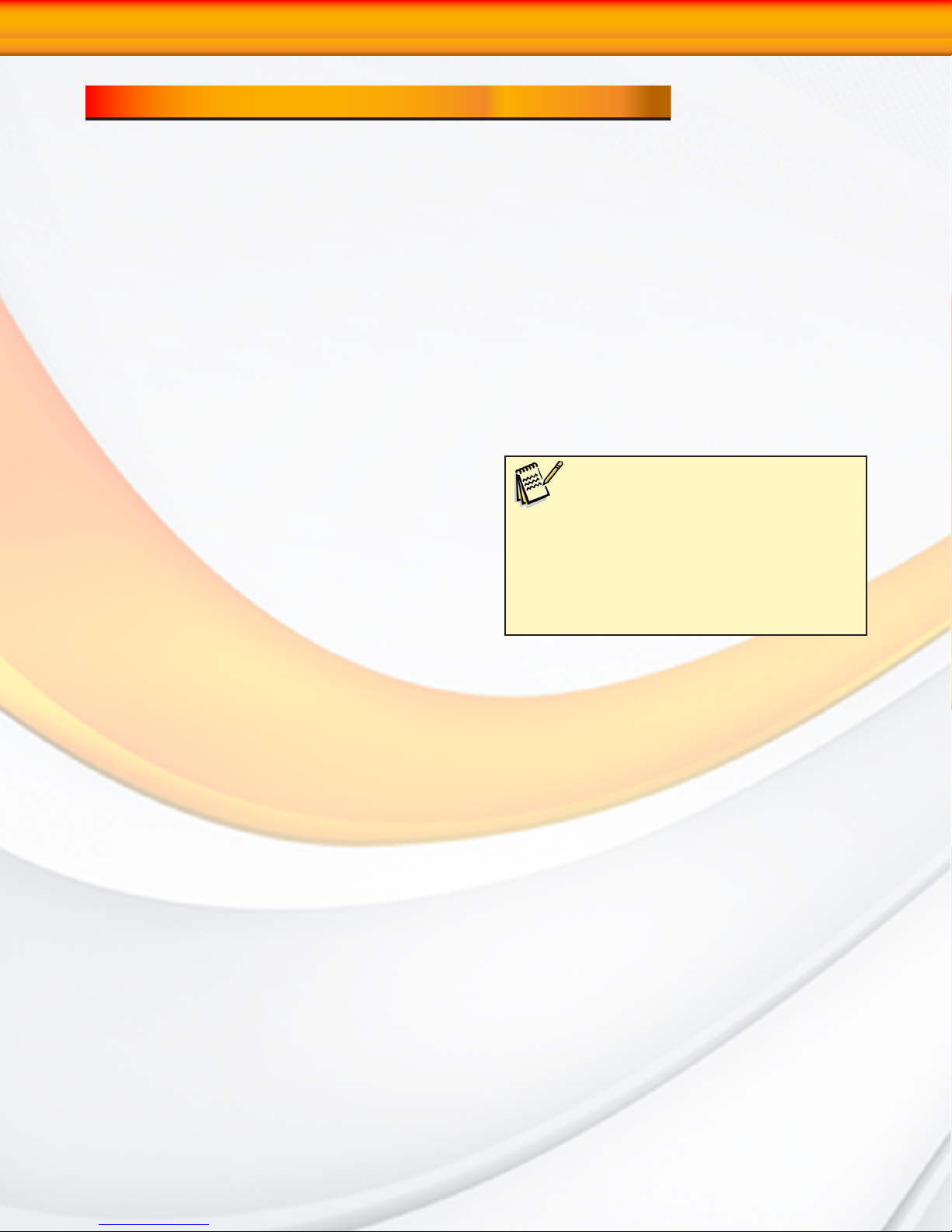
Using the RAID management Application
The MicroNet RAIDBank5 has a software configuration manager for users to administrate
one or multiple RAIDBank5 RAID subsystems attached to the host computer. Users need to
install the RaidBank5 Manager on the PC or MAC which the RAIDBank5 is connected to. The
RAIDBank5 Manager provides a simple graphic user interface that users can easily create
volumes, monitor hardware status, check event logs and upgrading the firmware, etc. There
are two modes in RAIDBank5 Manager: Basic Mode and Advanced Mode. In Basic Mode,
some basic functions are available, such as hard disk information, viewing event logs, creating
a RAID volume and setting one button backup. Advanced mode allows administration of email
notification, upgrading firmware and System information, etc. Refer to Chapter 4: RAIDBank5
Manager for more information.
Use to scroll the cursor Upward / Rightward
Use to scroll the cursor Downward / Leftward
Submit Selection Function (Confirm a selected item)
Return to Previous Screen (Exit a selection configuration)
RAIDBank5 Owner’s Manual
13
2-Understanding RAID
Chapter 2. Understanding RAID
The RAIDBank5 controller subsystem is a high-performance SATA2 drive bus disk array
controller. When properly configured, the RAIDBank5 can provide non-stop service with
a high degree of fault tolerance through the use of RAID technology and advanced array
management features.
The RAIDBank5 can be configured to RAID levels 0, 1, 10, 3, and 5, as well as disk spans
and direct mapping. RAID levels other than 0 are able to tolerate a hard disk failure without
impact on the existing data, and failed drive data can be reconstructed from the remaining
data and parity drives. RAID configuration and monitoring is accessible through the LCD
front control panel or the built in web administration interface. The RAIDBank5 features the
following high availability functions:
• RAID Levels 0,1,10,3,5, disk spans, and direct mapping Support
• Up to 4 discrete LUN support
• Online Capacity Expansion
• Online RAID Level Migration
• Logical Drive Capacity Extension
• Array Roaming
• Automatic Drive Failure Detection
• Automatic Failed Drive Rebuilding
• Hot Spare Disk Drives
• Instant Availability/Background Initialization.
techniques described by Garth Gibson, Randy Katz,
and David Patterson in papers written while they
were performing research into I/O subsystems at
the University of California at Berkeley. There are
six Berkeley RAID Levels, usually referred to by the
names RAID Level 1, etc., through RAID Level 6.
FYI:
The Berkeley RAID levels are a family of
disk array data protection and mapping
This section will help you gain understanding of how these functions can serve your needs best.
RAID
RAID is an acronym for Redundant Array of Independent Disks. It is an array of multiple
independent hard disk drives that provide high performance and fault tolerance through
support of several levels of the Berkeley RAID techniques. An appropriate RAID level is
selected when the volume sets are defined or created, and is based on disk capacity, data
availability (fault tolerance or redundancy), and disk performance considerations. The
RAIDBank5 controller makes the RAID implementation and the disks’ physical configuration
transparent to the host operating system, which means that the host operating system drivers
and software utilities are not affected regardless of the RAID level selected.
RAIDBank5 Owner’s Manual
14
A0
A1
A2
A3
B0
B1
B2
B3
C0
C1
C2
C3
D0
D1
D2
D3
Disk Spanning
2-Understanding RAID
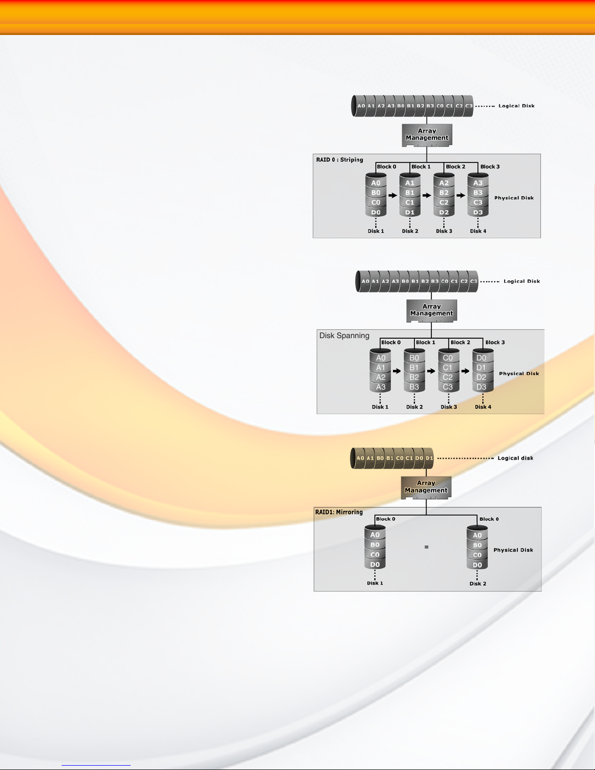
RAID 0 (Striping)
This RAID algorithm writes data across multiple disk drives instead of just one disk drive. RAID
0 does not provide any data redundancy, but
does offer the best high-speed data throughput.
RAID 0 breaks up data into smaller blocks and
then writes a block to each drive in the array.
Pros: Disk striping enhances both read and
write performance because multiple drives
are accessed simultaneously
Cons: The reliability of RAID Level 0 is less than
any of its member disk drives due to its lack
of redundancy.
Disk Spanning
This RAID algorithm writes data to multiple disk
drives sequentially. Spanning does not provide
any data redundancy, and is only as fast as a
single disk drive.
Pros: Disk spanning provides a large logical
volume from multiple smaller disks. The
entire disk capacity is available for user
access.
Cons: No fault tolerance, speed equivalent to a
single disk.
RAID 1 (Disk Mirroring, Cloning)
RAID 1, also known as “disk mirroring”, distributes
duplicate data simultaneously to 2 disk drives.
Pros: RAID 1 offers extremely high data reliability
as all the data is redundant. If one drive
fails, all data (and software applications)
are preserved on the other drive. Read
performance may be enhanced as the
array controller can access both members
of a mirrored pair in parallel.
Cons: RAID 1 volume requires double the raw
data storage capacity. During writes, there will be a minor performance penalty when
compared to writing to a single disk.
RAIDBank5 Owner’s Manual
15
 Loading...