

Page 1
Micronet SmartHubL T E Underdash
On Board Computer
Hardware Guide
Revision 1, July 2018
Page 2

Important Notice
© 2018 Micronet Ltd. All rights reserved.
Micronet Ltd. Reserves the right to alter the equipment specifications and descriptions in this publication
without prior notice. No part of this publication shall be deemed to be part of any contract or warranty
unless specifically incorporated by reference into such contract or warranty.
The information contained herein is merely descriptive in nature, and does not constitute a binding offer
for the sale of the product described herein.
All usage of the Micronet Ltd. Logotype or trademarks is forbidden without prior written approval from
Micronet Ltd.
Information in this manual is subject to change without notice.
Micronet maintains no liability or responsibility to any person or entity with respect to any loss or
damage arising from the information contained in this book.
Other company and brand products and service names are trademarks or registered trademarks of their
respective holders, for example: Google, Android, ADB, ADT, Eclipse and Android Studio.
Please refer to Micronet’s website (http://www.micronet-inc.com) for further information or contact us
directly (http://www.micronet-inc.com/contact-us/index.aspx)
Page 3

Table of Contents
Rev. 1
SmartHub OBC Hardware Guide
3 / 28
Table of Contents
Table of Contents........................................................................................................................ 3
Revision History .......................................................................................................................... 4
Safety Precautions ...................................................................................................................... 5
1. Introduction ...................................................................................................... 6
Micronet SmartHub-U Platform Overview ....................................................................................... 6
Micronet SmartHub-U Model ......................................................................................................... 6
Physical Interfaces .................................................................................................................... 6
Wireless Module ....................................................................................................................... 7
GSD™ Software Services ............................................................................................................. 7
GSD® Software Services .............................................................................................................. 7
Development Tool Kit .................................................................................................................. 8
Hardware ................................................................................................................................ 8
Software ................................................................................................................................. 8
Documentation ......................................................................................................................... 8
2. Micronet SmartHub-U Views ............................................................................. 9
Micronet SmartHub-U Front View .................................................................................................. 9
Figure 1: Micronet SmartHub Underdash Front Panel View .............................................................. 9
Micronet SmartHub-U Rear View ................................................................................................... 9
Figure 2: Micronet SmartHub Underdash Rear Panel View ............................................................... 9
Micronet SmartHub-U Bottom View .............................................................................................. 10
Micronet SmartHub-U TOP View ................................................................................................ 11
Micronet SmartHub-U Mounting Cradle ....................................................................................... 11
Introduction
3. Functional Details ........................................................................................... 13
Platform Core ............................................................................................................................ 13
User Interface ........................................................................................................................... 14
Sound ...................................................................................................................................... 15
Communication Interfaces .......................................................................................................... 15
Serial Communication .............................................................................................................. 15
USB Communication ................................................................................................................ 16
Peripheral Controls .................................................................................................................. 16
Wireless Communication ............................................................................................................. 17
Wireless LAN ........................................................................................................................... 17
Bluetooth 4.1 .......................................................................................................................... 17
Cellular Modem ....................................................................................................................... 18
GPS Receiver .......................................................................................................................... 18
Accelerometer ........................................................................................................................... 19
Wiggle Sensor ........................................................................................................................... 19
SAE J1939 CANBus .................................................................................................................... 19
Single Wire CANBus ................................................................................................................... 19
SAE J1708 ................................................................................................................................ 19
4. Main Cable Harness ......................................................................................... 20
5. Connector Signals Map .................................................................................... 21
Page 4
Introduction
Rev. 1
SmartHub Underdash OBC Hardware Guide
4 / 28
Revision
Date
Change
1
July 2018
Document created
Overview .................................................................................................................................. 21
Interface Connectors .................................................................................................................. 21
Main Connector Pinout ................................................................................................................ 22
Pinout by Functionality ............................................................................................................. 23
Secondary Connector Pinout ........................................................................................................ 24
Pinout by Pin Number ............................................................................................................... 24
Pinout by Functionality ............................................................................................................. 25
6. Platform Power ............................................................................................... 27
Overview .................................................................................................................................. 27
Super Capacitors ....................................................................................................................... 27
Device Power Consumption ....................................................................................................... 27
Electrical Installation Procedure ................................................................................................. 28
Revision History
Page 5
Introduction
Safety Precautions
Rev. 1
SmartHub Underdash OBC Hardware Guide
5 / 28
WARNING!
Abnormal Conditions
Should the SmartHub Underdash become hot, start to emit smoke or a strange odor,
immediately turn off the power and contact your original dealer or authorized service
provider. Continued usage is dangerous and may result in fire or electric shock.
WARNING!
Foreign Objects
Avoid having foreign matter or objects enter into any opening of the SmartHub Underdash.
This could result in fire or electric shock. Immediately turn off the power and contact your
original dealer or an authorized service provider.
WARNING!
Location and Physical Damage
If the SmartHub Underdash falls and is damaged, turn off the power immediately and
contact the original dealer or authorized service provider. Continuing to use the device in
this state or locating the device in extremely humid or dusty areas is dangerous and may
result in fire or electric shock.
WARNING!
Liquids
Keep the device away from water, other liquids and liquid containers. Liquid entering into
the device can cause fire and electric shock.
CAUTION
Power Supply
Do not use the SmartHub Underdash with any voltage other than that specified. Avoid
situations that can cause damage to the power cable. Do not place heavy objects on the
power cable and keep it away from sources of heat. Never twist, sharply bend, or pull the
power cable. If the power cable is damaged (exposing or breaking wires), contact your
original dealer or service provider about repair or replacement. Damage to the electrical
cable may result in fire or electrical shock.
Safety Precautions
Read the following safety precautions before installation or operation.
Page 6

Introduction
Micronet SmartHub-U Platform Overview
Rev. 1
SmartHub Underdash OBC Hardware Guide
6 / 28
1. Introduction
Micronet SmartHub-U Platform Overview
Micronet SmartHub Underdash is a rugged, next generation Android On-Board Telematics Computer. It
provides a rugged and versatile vehicle-centric mobile-computing platform for a variety of in-cab
mobility applications and solutions.
With integrated GPS, Cellular Communication, Wi-Fi, BT, cameras and various sensors and with support
for a suite of vehicle and peripheral interfaces - SmartHub Underdash enables a host of advanced
mobility solutions such as: Fleet Management, ELD BYOD HOS, Driver Behavior, ADAS, Video Analytics,
Driver Distraction Alerts, Routing and Dispatch, Fuel Efficiency, Speed by Street, Navigation, Fleet
Tracking, Driver Interaction and more.
Designed to operate in a rough commercial automotive environment, including a wide range of
temperatures, vibrations and shocks, the Micronet SmartHub Underdash provides Enhanced Solution Life
Cycle.
The SmartHub Underdash platform supports the Google AndroidTM 5.1.1 operating system.
Micronet SmartHub-U Model
Micronet implemented the SmartHub Underdash installation, mounted under the dashboard or another
hidden place on the vehicle. Include internal Cellular antennas and GPS SMA connector for external
active antenna. The SmartHub Underdash provides the key feature set, described in configuration
chapter below.
In addition, optional features, accessories and OEM features are available as follows:
Platform accessories - provides accessory features such as mounting cradle.
OEM optional features - provides OEM optional features such as branding and labeling
Addition information on Micronet SmartHub Underdash can be viewed in Micronet's web site
http://www.micronet-inc.com/products/smarthub/.
Physical Interfaces
The Micronet SmartHub Underdash provides the following physical interfaces:
USB Client and Host
Serial RS232
Interfaces for vehicle such as CANBus and J1708
Page 7

Introduction
GSD™ Software Services
Rev. 1
SmartHub Underdash OBC Hardware Guide
7 / 28
A2D and Digital input signals for ignition switch control and other I/Os
Digital control output signals
Wireless Module
The Micronet SmartHub Underdash supports 3.5G and 4G LTE cellular communication and GPS.
GSD™ Software Services
Micronet’s GSD™ (Guardian System Design) is a cloud-based SaaS platform for managing mobile
devices in the field.
GSD™ enables remote, delta-based, Over-The-Air Firmware and Application Updates, allowing
customers to keep devices relevant anywhere, anytime. It features Mobile Device Management
functionality, Remote Control and Self-Diagnostic.
Administrators can proactively monitor and manage connected devices with a flexible web interface.
GSD® Software Services
Introducing; GSD® - Advanced software tools to manage and support mobile devices in the field.
Micronet’s new comprehensive software framework called GSD® - Guardian System Design - is a cloud-
based Software-as-a-Service platform that provides advanced software tools to manage and support
applications and system firmware upgrades on Micronet and third party devices installed in the field. The
GSD® enables remote, over-the-air, access and control of Android based mobile devices, to conduct
individual, or group diagnostics, support and training activity.
GSD® a fully integrated software framework enabling new levels of control, support and corporate policy
compliance
GSD® is offered on Micronet’s SmartHub Underdash series of rugged, automotive-grade, MDTs. It
enables both firmware and application software to be remotely managed, and simplifies maintenance,
trouble-shooting and remote training, significantly reducing operational costs over the life time of the
product, and substantially improving user experience and customer satisfaction.
GSD® features white-label cloud-based software as a service solutions, offered as two key services:
Mobile Device Management and remote control
Fail-safe firmware and application over-the-air updates (FOTA/OTA)
Page 8

Introduction
Development Tool Kit
Rev. 1
SmartHub Underdash OBC Hardware Guide
8 / 28
Development Tool Kit
Micronet's SmartHub Underdash Development Package provides all the tools required for product
evaluation, application development quick-start, and product testing. The Developers Package contains
all essential hardware and software components as described in the following sections.
Hardware
Micronet SmartHub Underdash OBC
Wall power supply
Mechanical and interface connection accessories
Main cable harness
Mounting accessories
Software
Software Development Kit (SDK) provides a set of software tools and API documentation.
Android demo samples for some device features including the source code.
Documentation
Micronet SmartHub-U Hardware guide
Micronet SmartHub-U Getting Started guide
Micronet SmartHub-U OS Update guide
Micronet SmartHub-U Remote Control and Display guide
Page 9
Micronet SmartHub-U Views
Micronet SmartHub-U Front View
Rev. 1
SmartHub Underdash OBC Hardware Guide
9 / 28
Customized Logo
Mounting Cradle
2. Micronet SmartHub-U Views
This chapter describes the SmartHub Underdash views and the functionalities on each view.
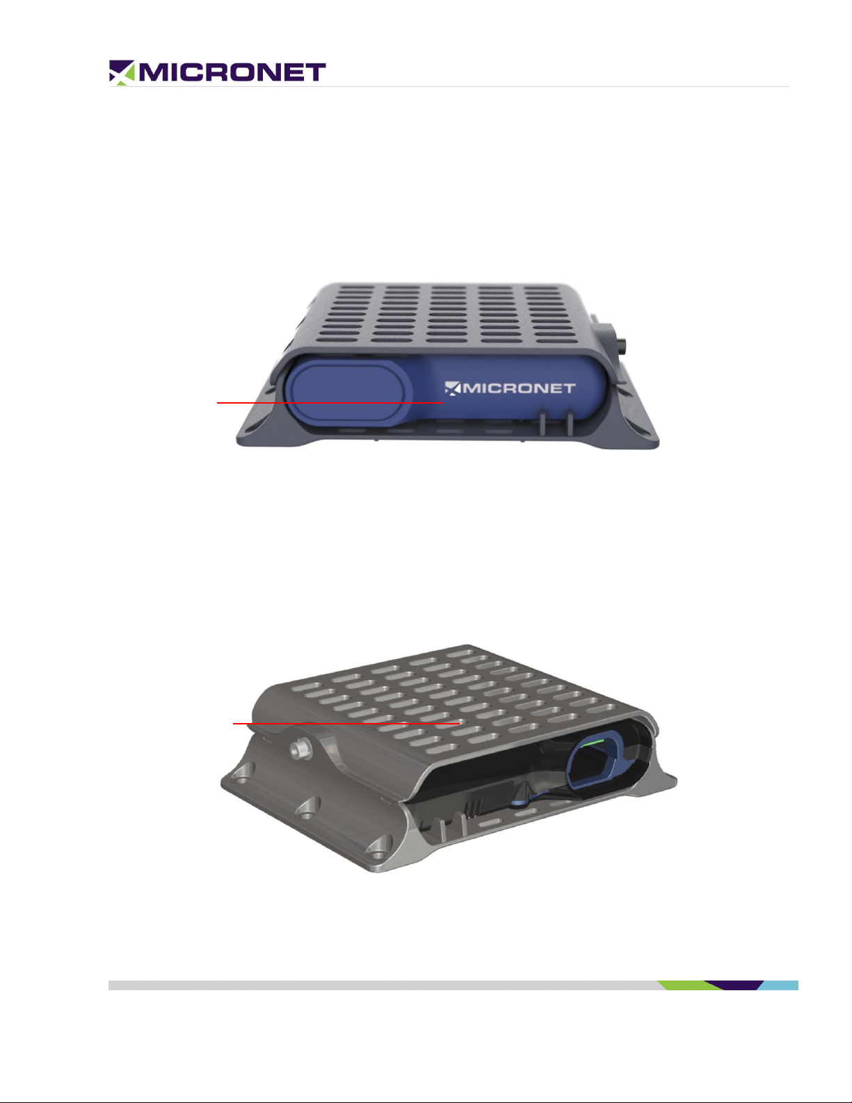
Micronet SmartHub-U Front View
Figure 1: Micronet SmartHub Underdash Front Panel View
For more information about the Micronet SmartHub Underdash front panel view, see:
Customized Logo, on page 14
Micronet SmartHub-U Rear View
Figure 2: Micronet SmartHub Underdash Rear Panel View
For more information about the Micronet SmartHub Underdash rear panel view, see:
Page 10

Micronet SmartHub-U Views
Micronet SmartHub-U Bottom View
Rev. 1
SmartHub Underdash OBC Hardware Guide
10 / 28
LED indicator
Reset Button
Mounting Cradle, on page 11
Micronet SmartHub-U Bottom View
Figure 3: Micronet SmartHub Underdash Front Panel View
For more information about the Micronet SmartHub Underdash bottom panel view, see:
LED Indicator, on page 14
Reset Button, if needed, a reset button resets the SmartHub Underdash and reboots depends on the ignition
switch input state.
Page 11

Micronet SmartHub-U Views
Micronet SmartHub-U Bottom View
Rev. 1
SmartHub Underdash OBC Hardware Guide
11 / 28
Micro SIM and
MicroSD Cards
Compartment
Micronet SmartHub-U TOP View
Figure 4: Micronet SmartHub Underdash Top Panel View
For more information about the SmartHub Underdash top panel component, see:
MicroSD Memory Card Slot, on page 14
MicroSIM card slot, on page 18
Micronet SmartHub-U Mounting Cradle
Mounting Cradle
The SmartHub Underdash mounting cradle is used for mounting the OBC under the vehicle
dashboard or any place in the vehicle cabin.
The cradle consists of two parts, base and cover, with ventilation holes for Effective heat dissipation
of the SmartHub Underdash OBC device.
Page 12

Micronet SmartHub-U Views
Micronet SmartHub-U Bottom View
Rev. 1
SmartHub Underdash OBC Hardware Guide
12 / 28
Mounting Cradle Cover
with ventilation holes
Mounting Cradle Base
with ventilation holes
Lock Screw
Mounting Cradle Screw Holes
Mounting Cradle Screw Holes
Hooks on one side of the cradle and a screw are used to mount the device inside the cradle. Before
hooking the OBC, the MicroSIM and optionally MicroSD card should be insert on the dedicated
compartment on the top side of the device.
The cradle has six holes to assemble under the dashboard of to another place.
Figure 5: Micronet SmartHub Underdash Mounting Cradle Right View
Figure 6: Micronet SmartHub Underdash Mounting Cradle Left View
Page 13

Functional Details
Platform Core
Rev. 1
SmartHub Underdash OBC Hardware Guide
13 / 28
3. Functional Details
Platform Core
Operating System
The SmartHub Underdash OBC is powered by Google Android
TM
5.1.1 Lollipop.
ELD Compliance
The Micronet SmartHub Underdash system boot time is ~40 seconds. The ELD requirement is up to 1
minute.
Application Development Environment
The SmartHub Underdash OBC supports any open source IDE. Micronet recommends using the Android
Studio IDE.
Micronet’s Development Toolkit (DTK) includes the following components:
Full Micronet SDK
Application sample demonstrates the Micronet’s proprietary API
Device management and upload tools
Development accessories
Documentation
For more details about the development infrastructure, product tools, and DTK contents, please refer to
the "Micronet SmartHub Underdash OBC Getting Started" Guide.
Processor
Qualcomm Snapdragon 410 - 1.2GHz Quad Core
High-performance Superscalar 4x ARM® Cortex™ A53
Co-Processor
Freescale K20_120
MQX RTOS
RAM
1GB LPDDR3 RAM memory
Page 14

Functional Details
User Interface
Rev. 1
SmartHub Underdash OBC Hardware Guide
14 / 28
Flash Memory
8GB eMMC
MicroSD Memory Card Slot
The MicroSD card slot is located on the Micronet SmartHub Underdash top panel cards compartment.
Watchdog
To monitor mission-critical processes, the platform provides an intelligent watchdog mechanism. This
mechanism provides various capabilities for guard and restarts the OBC if the system hangs.
The Android provides a level of watchdog mechanism by the "Applications Manage" to control application
stability.
User Interface
LED Indicator
The SmartHub Underdash OBC includes one LED on the front panel, controlled by the OS.
Customized Logo
Micronet provides the option to attach a customized logo based on your specifications. To enable
rebranding the product, Micronet will provide graphic files and size specifications. This is subject to
an additional charge per unit and MOQ.
Page 15

Functional Details
Sound
Rev. 1
SmartHub Underdash OBC Hardware Guide
15 / 28
Sound
Speakers
The SmartHub Underdash OBC provides external speaker connection through the main cable harness.
Microphone
The SmartHub Underdash OBC provides external speaker connection through the main cable harness.
Figure 7: Customized Logo
Communication Interfaces
Serial Communication
The SmartHub Underdash OBC supports 4 serial communication ports for external devices and
peripheral connections and a debug port connected to the Co-Processor. These ports support various
hardware and software flow control functions.
Serial Port 1 (COM1)
The SmartHub Underdash OBC supports an EIA-RS232 level serial communication port. The port
supports a baud rate of 300 to 115,200bps, and provides one pair of communication-control handshake
signals (CTS / RTS).
Serial Ports 2-4 (COM2-4)
The SmartHub Underdash OBC supports EIA-RS232 level serial communication ports 2-4. The ports
support a baud rate of 300 to 115,200bps, and provide the TX and RX signals only.
Page 16

Functional Details
Communication Interfaces
Rev. 1
SmartHub Underdash OBC Hardware Guide
16 / 28
NOTE:
The USB Host port provides up to 500 mA of power consumption for non-self-powered
client devices.
Debug Serial Port (COM7)
The SmartHub Underdash OBC supports EIA-RS232 level serial communication port for Co-Processor
debugging purposes. The port supports a baud rate of 300 to 115,200bps, and provides the TX and RX
signals only.
USB Communication
The SmartHub Underdash OBC supports two USB ports (Universal Serial Bus), one USB Host port for
external device/peripheral connections, the second USB is a USB Client.
USB Host
The USB Host Port connects to the main device connector. This port supports the USB2.0 low, full, and
high-speed communications standards.
The USB Host interface supports the following profiles:
USB Standard HID
USB Printer (PCL)
USB Storage
For more information about these interface signals please see the USB Host 1 signal map on page 26.
USB Client
The USB Client interface supports Android ADB for application development, device configuration and
management, and for application debugging.
Peripheral Controls
Analog and Digital Input lines
The SmartHub Underdash OBC provides seven automotive input lines (0-32V). The input lines can be
configured as digital or analog lines.
IGN (automotive voltage level) is for monitoring the ignition switch signal. The other inputs can be used
for any purpose, like sensing door opening, sensing bus amber lights, etc.
The input signals are provided on the main 44 pins connector and on the DVI connector.
Page 17

Functional Details
Wireless Communication
Rev. 1
SmartHub Underdash OBC Hardware Guide
17 / 28
NOTE:
INP1 is also used to power on the device from shutdown state. For proper power
management implementation, the input should be connected to the vehicle's ignition
switch.
Open Collector Outputs
The SmartHub Underdash OBC provides four O.C output lines for external peripheral control.
Wireless Communication
Wireless LAN
Overview
The SmartHub Underdash OBC provides a Wireless Local Area Network (IEEE 802.11) module.
Wireless LAN communication is especially suited for high-speed data transfer over the air, when a
Wireless LAN hotspot infrastructure exists. For applications that require large data transactions, Wireless
LAN is the most economical way to implement the solution.
Bluetooth communication is used for Bluetooth-enabled connections with peripherals such as an audio
headset and printer.
Wireless LAN Operation
The WLAN module is compliant with the IEEE 802.11 b/g/n standard and uses DSSS (Direct Sequence
Spread Spectrum), OFDM (Orthogonal Frequency Division Multiplexing), DBPSK, DQPSK, CCK, and QAM
baseband modulation technologies.
In addition to supporting WPA / WPA2, WEP 64-bit, and 128-bit encryption, this module supports the
following:
IEEE’s 802.11i security standard through the implementation of AES (Advanced Encryption Standard), CCMP (Counter
Mode CBC-MAC Protocol), and WEP with TKIP security mechanisms.
IPsec with DES / 3DES / ASE encryption and MD5 / SHA-1 authentication
(the AW-GH381 supports) 802.11e QoS (Quality of Service) for voice applications
Bluetooth 4.1
The SmartHub Underdash OBC provides a Bluetooth 4.1 BLE module.
Page 18

Functional Details
Wireless Communication
Rev. 1
SmartHub Underdash OBC Hardware Guide
18 / 28
Cellular Modem
The Micronet SmartHub Underdash OBC provides cellular modem with the following bands:
3.5G GSM for Europe - B8/900 and B3/1800, DC-HSPA+ B1/2100 and B8/900 bands.
4G AT&T LTE for NA - AT&T and T-Mobile B2 1900MHz, B4 AWS1700MHz, B5 850MHz,
B12/B13 700MHz; 3G B2 1900MHz, B5 850MHz
MicroSIM card slot
The GSM modem requires a MicroSIM card connection. The MicroSIM card slot is located on the top
panel compartment of the OBC.
Cellular Antenna
The Micronet SmartHub Underdash has two Main and Diversity internal integrated antennas.
GPS Receiver
The Micronet SmartHub Underdash OBC provides a high sensitive GPS receiver support 50 channels,
NMEA0183 standard sentences, AGPS, GPS and GLONASS satellites.
GPS Antenna
The Micronet SmartHub Underdash OBC has an SMA connector for external ACTIVE antenna.
Page 19

Functional Details
Accelerometer
Rev. 1
SmartHub Underdash OBC Hardware Guide
19 / 28
Accelerometer
The Micronet SmartHub Underdash OBC provides an Accelerometer, Compass and Gyroscope module.
The accelerometer is an electromechanical device used to measure acceleration forces. Such forces may
be static like the continuous force of gravity or, as is the case with many mobile devices, dynamic to
sense movement or vibrations.
Acceleration is the measurement of the change in velocity or speed divided by time. For example, a car
accelerating from a standstill to 60 mph in six seconds is determined to have an acceleration of 10 mph
per second (60 divided by 6).
Wiggle Sensor
The Micronet SmartHub Underdash OBC provides automatic Power-up trigger to turn on the device when
sensing movement of the vehicle or closing the vehicle door.
SAE J1939 CANBus
The SmartHub Underdash OBC provides two SAE J1939 CANBus ports that enable the connection of a
variety of vehicle peripherals, such as the vehicle's computer, vehicle's sensors and so on.
Single Wire CANBus
The Micronet SmartHub Underdash provides a single wire CANBus port through its main cable.
SAE J1708
The SmartHub Underdash OBC provides SAE J1708 port. The SAE J1708 is a standard used for serial
communications between ECUs on a heavy-duty vehicle and between a computer and the vehicle. With
respect to Open System Interconnection model (OSI), J1708 defines the physical layer.
Page 20

Main Cable Harness
SAE J1708
Rev. 1
SmartHub Underdash OBC Hardware Guide
20 / 28
4. Main Cable Harness
Every customer designs its main cable according the main connectors on the SmartHub Underdash
PCBA describes in Interface Connectors section below.
In addition, Micronet provides engineering cable design for its customers if necessary, the customers
can manufacture the cable according Micronet's scheme or according to their design.
Figure 8: SmartHub Underdash OBC Interface connectors
Page 21

Connector Signals Map
Overview
Rev. 1
SmartHub Underdash OBC Hardware Guide
21 / 28
5. Connector Signals Map
Overview
This chapter describes the SmartHub Underdash OBC interface connectors and signals found on the
main and secondary connectors.
The following abbreviations are used:
I - Input signal
O - Output signal
B - Bus signal
V - Voltage signal
G – Ground
P – Positive
N – Negative
Interface Connectors
The SmartHub Underdash OBC interface contains Molex Pico-Clasp™ Wire-to-Board Header 1.00 mm
pitch 20 and 50 pin connectors. All pins are ESD protected (against electrostatic discharge). The Main
Connector Pinout and Secondary Connector Pinout tables below describe the pinout of each connector.
Figure 9: SmartHub Underdash OBC Interface connectors
Page 22

Connector Signals Map
Main Connector Pinout
Rev. 1
SmartHub Underdash OBC Hardware Guide
22 / 28
Pin
Signal
Type
Function
Specifications
1
+VIN
V
Input Power
12V/24V
Typical – 12V/24V
- Minimum continues – 6V (5V for up to
40ms according to ISO7637)
- Maximum continues – 32V
2
+VIN
V
3
VIN_GND
G
Ground
4
VIN_GND
G
5
Ignition Input
A
A2D Input
Ignition switch
Typical Min Max
Input Low: VIL 0V -30V 6V
Input High: VIH 12V-24V +8V +32V
6
I/O
CAN High Signal
7
8
I/O
CAN Low Signal
9
10
I/O
CAN High Signal
11
G
Ground
12
I/O
CAN Low Signal
13
V
USB Host Port VBUS
USB 2.0
14
P
J1708 Positive Signal
Figure 10: Main 20 pin connector
Main Connector Pinout
The following table lists the main 20 pin connector signals by pin number.
Table 1: Main Connector Signal Map (by Pin Number)
Page 23

Connector Signals Map
Main Connector Pinout
Rev. 1
SmartHub Underdash OBC Hardware Guide
23 / 28
Pin
Signal
Type
Function
Specifications
15
B
USB Host Port1 Data-
USB 2.0
16
N
J1708 Negative Signal
17
B
USB Host Port1 Data+
USB 2.0
18
SWC
I/O
CAN
Single wire CAN
19
USB Host 1 GND
G
Ground
USB 2.0
20
GND
G
Ground
Pin
Signal
Type
Function
Specifications
1
VIN_GND
G
MDT Power supply
Ground
2
VIN_GND
G
3
+VIN
V
Input Power
12V/24V
Typical – 12V/24V
- Minimum continues – 8V
- Maximum continues – 32V
4
+VIN
V
5
Ignition Input
A
Ignition switch
Typical Min Max
Input Low: VIL 0V -30V 6V
6
CAN1 H
I/O
CAN High Signal
8
CAN1 L
I/O
CAN Low Signal
10
CAN2 H
I/O
12
CAN2 L
I/O
18
SWC
I/O
CAN
Single wire CAN
14
J1708 P
P
J1708 Positive Signal
16
J1708 N
N
J1708 Negative Signal
13
V
USB Host Port VBUS
USB 2.0
15
USB Host 1 D-
B
USB Host Port1 Data-
USB 2.0
17
USB Host 1 D+
B
USB Host Port1 Data+
USB 2.0
19
USB Host 1 GND
G
Ground
USB 2.0
Pinout by Functionality
The following table lists the 20 pin connector signals by functionality.
Table 2: Main Connector Signal Map (by functionality)
Page 24

Connector Signals Map
Secondary Connector Pinout
Rev. 1
SmartHub Underdash OBC Hardware Guide
24 / 28
Pin
Signal
Type
Function
Specifications
11
G
20 G
Pin
Signal
Type
Function
Specifications
1
Automotive Input
I
Digital Input 1
Typical Min Max
Input Low: VIL 0V -30V 6V
Input High: VIH 12V-24V +8V +30V
0V-30V max, 12k OHM
2
3
I
Typical Min Max
Input Low: VIL 0V -30V 6V
4
5
I
Digital Input 3
Typical Min Max
Input Low: VIL 0V -30V 6V
Input High: VIH 12V-24V +8V +30V
6
7
I
Digital Input 4
Typical Min Max
Input Low: VIL 0V -30V 6V
Input High: VIH 12V-24V +8V +30V
8
9
I
Digital Input 5
Typical Min Max
Input Low: VIL 0V -30V 6V
Input High: VIH 12V-24V +8V +30V
10
G
Ground
11
I
Digital Input 6
Typical Min Max
Input Low: VIL 0V -30V 6V
Input High: VIH 12V-24V +8V +30V
12
Secondary Connector Pinout
Pinout by Pin Number
The following table lists the 50 pin connector signals by pin number.
Table 3: Secondary Connector Signal Map (by Pin Number)
Page 25

Connector Signals Map
Secondary Connector Pinout
Rev. 1
SmartHub Underdash OBC Hardware Guide
25 / 28
Pin
Signal
Type
Function
Specifications
13
I
Digital Input 7
Typical Min Max
Input Low: VIL 0V -30V 6V
Input High: VIH 12V-24V +8V +30V
14
15
G
Ground
16-19
20
G
Ground
21
G
Ground
22
23
G
Ground
24-40
41
USB OTG +5V
V
USB OTG VBUS
USB 2.0
42
GND G Ground
43
USB OTG D-
B
USB OTG Data-
USB 2.0
44
GND G Ground
45
USB OTG D+
B
USB OTG Data+
USB 2.0
46
GND G Ground
47 B USB 2.0
48 G Ground
49 G Ground
USB 2.0
50
GND
G
Ground
Pin
Signal
Type
Function
Specifications
1
Automotive Input
I
Digital Input 1
Typical Min Max
Input Low: VIL 0V -30V 6V
Input High: VIH 12V-24V +8V +30V
0V-30V max, 12k OHM
Pinout by Functionality
The following table lists the 50 pin connector signals by functionality.
Table 4: Secondary Connector Signal Map (by Functionality)
Page 26

Connector Signals Map
Secondary Connector Pinout
Rev. 1
SmartHub Underdash OBC Hardware Guide
26 / 28
Pin
Signal
Type
Function
Specifications
3
Automotive Input
I
Digital Input 2
Typical Min Max
Input Low: VIL 0V -30V 6V
Input High: VIH 12V-24V +8V +30V
5
Automotive Input
I
Digital Input 3
Typical Min Max
Input Low: VIL 0V -30V 6V
Input High: VIH 12V-24V +8V +30V
7
Automotive Input
I
Digital Input 4
Typical Min Max
Input Low: VIL 0V -30V 6V
Input High: VIH 12V-24V +8V +30V
9
Automotive Input
I
Digital Input 5
Typical Min Max
Input Low: VIL 0V -30V 6V
Input High: VIH 12V-24V +8V +30V
11
Automotive Input
I
Digital Input 6
Typical Min Max
Input Low: VIL 0V -30V 6V
Input High: VIH 12V-24V +8V +30V
13
Automotive Input
I
Digital Input 7
Typical Min Max
Input Low: VIL 0V -30V 6V
Input High: VIH 12V-24V +8V +30V
41
V
USB OTG VBUS
USB 2.0
43
B
USB OTG Data-
USB 2.0
45
B
USB OTG Data+
USB 2.0
47
B
USB OTG Identifier
USB 2.0
49
G
Ground
USB 2.0
10
GND G Ground
15
GND G Ground
20
GND G Ground
21
GND G Ground
23
GND G Ground
42
GND G Ground
44
GND G Ground
46
GND G Ground
48/50
GND G Ground
Page 27

Platform Power
Overview
Rev. 1
SmartHub Underdash OBC Hardware Guide
27 / 28
SmartHub Underdash Current Consumption
Power OFF
Operational mode
12V
24V
~10mA
~7mA
250mA
130mA
6. Platform Power
Overview
The SmartHub Underdash power comes directly from the vehicle's 12V/24V DC battery and provides
intelligent power management options that reduce drain on the vehicle’s battery.
Super Capacitors
The SmartHub Underdash has a super capacitor inside to:
Provide power backup if the main power source is disconnected.
Provide power backup during an ignition event (vehicle start up).
The SmartHub Underdash automatically manages power and super capacitor charging. The
operation time of the SmartHub Underdash while powered by the internal super capacitor is
dependent on the peripherals and applications being used. Nevertheless, the estimated time of
continued operation for standard applications is ~20 seconds.
The super capacitor will take approximately 20 minutes to charge when the device is first powered
on by the battery. After 20 minutes, the super capacitor should be fully charged and will provide up
to 20 seconds of backup power to the device.
When power is initially connected to the SmartHub Underdash, charging on the super capacitor
starts. The SmartHub Underdash may not power up immediate as the systems is waiting for the
super capacitor to reach a predetermined value. This initial charging could take up to 1min before
the power LED turns on. Power may be connected to the SmartHub Underdash at any time.
Device Power Consumption
Table 5: SmartHub Underdash Current Consumption
Page 28

Platform Power
Super Capacitors
Rev. 1
SmartHub Underdash OBC Hardware Guide
28 / 28
Electrical Installation Procedure
1. Prepare the wiring for power and all other required peripherals in the vehicle, for connection to the
SmartHub Underdash main harness cable.
2. Connect the main harness cable 20 pins and 50 pins Molex connectors to the SmartHub Underdash
connectors inside the cable compartment.
3. The power signals from the main harness cable should be connect to the vehicle's power line
protected by a 10A fuse. An inline 3A "Slow Blow" fuse (with fuse holder for HHC/HHD blade-type
fuses) should be add to the main power cable.
4. To power on the SmartHub Underdash turn on the ignition switch or to hit the SmartHub Underdash, the
wiggle sensor will turn on the device.
Figure 11: Electrical Installation Scheme
Page 29

FCC Statement
Changes or modifications not expressly approved by the party responsible for compliance could void the user's
authority to operate the equipment.
This equipment has been tested and found to comply with the limits for a Class B digital device, pursuant to Part 15
of the FCC Rules. These limits are designed to provide reasonable protection against harmful interference in a
residential installation. This equipment generates uses and can radiate radio frequency energy and, if not installed
and used in accordance with the instructions, may cause harmful interference to radio communications. However,
there is no guarantee that interference will not occur in a particular installation. If this equipment does cause
harmful interference to radio or television reception, which can be determined by turning the equipment off and on,
the user is encouraged to try to correct the interference by one or more of the following measures:
-- Reorient or relocate the receiving antenna.
-- Increase the separation between the equipment and receiver.
-- Connect the equipment into an outlet on a circuit different from that to which the receiver is connected.
-- Consult the dealer or an experienced radio/TV technician for help
This device complies with part 15 of the FCC rules. Operation is subject to the following two conditions (1)this device
may not cause harmful interference, and (2) this device must accept any interference received, including interference
that may cause undesired operation.
 Loading...