

Page 1
Net-960CE-S
Mobile Data Terminal
Hardware Guide
June, 2007
Page 2

Net-960CE-S MDT Platform – Introduction
2
Net-960CE-S MDT Hardware Guide
Important Notice
Micronet Ltd. All rights reserved.
Micronet Ltd. reserves the right to alter the equipment specifications and
descriptions in this publication without prior notice. No part of this publication
shall be deemed to be part of any contract or warranty unless specifically
incorporated by reference into such contract or warranty.
The information contained herein is merely descriptive in nature, and does not
constitute a binding offer for the sale of the product described herein.
All usage of the Micronet Ltd. logotype or trademarks is forbidden without prior
written approval from Micronet Ltd.
Information in this manual is subjected to change without notice.
Micronet shall have neither liability nor responsibility to any person or entity with
respect to any loss or damages arising from the information contained in this book.
Other company and brand products and service names are trademarks or registered
trademarks of their respective holders.
For further information, contact Micronet Ltd, as follows:
Email:
Web: www.micronet.co.il
sales@micronet.co.il
Page 3

Introducing the Net-960CE-S
Net-960CE-S MDT Hardware Guide
About This Guide
This guide is comprised of the following chapters:
3
• Chapter 1, Introducing the Net-960CE-S, page
10, introduces the
Net-960CE-S MDT platform, the developers' package, application
development tools and the front and back panel of the Net-960CE-S
devices.
• Chapter 2, Net-960CE-S Technical and Functional Description,
page
18, provides the specifications of the Net-960CE-S's basic
configuration and additional options followed by a more detailed
description of each of these features.
• Chapter 3, Net-960CE-S Power, page
36, describes the various
aspects of Net-960CE-S power, such as power management, battery
voltage, peripheral voltage supply and power down control.
• Chapter 4, Net-960CE-S Signal Maps, page
42, provides various
tables mapping the power and communication signals of the
Net-960CE-S ports.
• Chapter 5, Net-960CE-S Installation, page
58, describes the
installation procedure of the Net-960CE-S devices, including bracket
mounting, protective back cover mounting and electrical installation.
Page 4

Net-960CE-S MDT Platform – Introduction
4
Net-960CE-S MDT Hardware Guide
Table of Contents
Chapter 1, Introducing the Net-960CE-S.........................................10
Net-960CE-S MDT Platform – Introduction ......................................................................11
Developers Package and Application Development Tools.................................................12
The Net-960CE-S Device ......................................................................................................13
Chapter 2, Net-960CE-S Technical and Functional Description... 18
Net-960CE-S MDT – Specifications.....................................................................................19
Computer Environment........................................................................................................22
System and Application Memory.......................................................................................22
Real Time Clock (RTC) .....................................................................................................23
User Interfa ce Options ..........................................................................................................24
Terminal Display................................................................................................................24
Customized Front Panel Label............................................................................................24
Control Knob......................................................................................................................24
Keyboard ............................................................................................................................25
Alert LEDs..........................................................................................................................25
External Display....................................................................................................................26
Voice Options.........................................................................................................................26
Buzzer.................................................................................................................................26
Audio Codec.......................................................................................................................26
Communication.....................................................................................................................27
Serial Communication........................................................................................................27
USB Device Port ................................................................................................................30
USB Host Ports...................................................................................................................30
CANBus Port......................................................................................................................30
Wireless Communication ...................................................................................................31
Control Signals......................................................................................................................34
Digital Signals ....................................................................................................................34
Analog Signals....................................................................................................................35
Peripheral Support – Dedicated Ports.................................................................................35
Page 5

Introducing the Net-960CE-S
Net-960CE-S MDT Hardware Guide
Chapter 3, Net-960CE-S Power .........................................................36
Overview ...............................................................................................................................36
Battery Voltage Input...........................................................................................................37
Power Management.............................................................................................................. 38
Watchdog .............................................................................................................................. 38
Manual Reset and Boot Mode.............................................................................................39
Peripherals Voltage Supply................................................................................................. 40
Chapter 4, Net-960CE-S Signal Maps...............................................42
Serial Port 1 (SER1 Connector)..........................................................................................43
Serial Port 2 (SER2 Connector)..........................................................................................45
Serial Port 3 (SER3 Connector)..........................................................................................46
Serial Port 4 (SER4 Connector)..........................................................................................48
USB Device Connector......................................................................................................... 49
USB Host Connectors........................................................................................................... 50
EXT1 Connector................................................................................................................... 51
EXT2 Connector................................................................................................................... 52
EXT3 Connector................................................................................................................... 53
GPS Antenna Connector...................................................................................................... 54
Cellular Modem Antenna Connector..................................................................................54
Wireless LAN Antenna Connector......................................................................................55
External Speaker Connector ............................................................................................... 55
AV Connector....................................................................................................................... 56
Microphone Connector........................................................................................................56
SIM Card Connector............................................................................................................ 56
5
Chapter 5, Net-960CE-S Installation.................................................58
Mechanical Installation........................................................................................................ 59
Mounting the Net-960CE-S MDT - Standard Model.........................................................59
Mounting the Net-960CE-S MDT - Screenless Model......................................................60
Electrical Installation........................................................................................................... 61
Power Cable Wires ............................................................................................................ 61
Power Protection Fuse ....................................................................................................... 61
Vehicle Ignition Switch Connection.................................................................................. 62
Page 6

Net-960CE-S MDT Platform – Introduction
6
Net-960CE-S MDT Hardware Guide
Appendix A, Net-960CE-S Certifications......................................... 64
Page 7

Introducing the Net-960CE-S
Net-960CE-S MDT Hardware Guide
Table of Figures
Figure 1: NET-960CE-S Standard Model – Front Panel Components....................................... 14
Figure 2: NET-960CE-S Screenless Model – Side Panel ........................................................... 15
Figure 3: NET-960CE-S – Back Panel Components .................................................................. 16
Figure 4: NET-960CE-S Standard Model – Bottom Panel......................................................... 17
Figure 5: NET-960CE-S Screenless Model – Bottom Panel.......................................................17
Figure 6: Mechanical Installation – Standard Model.................................................................. 59
Figure 7: Mechanical Installation – Screenless Model................................................................60
Figure 8: SER 1 Connector Wiring Scheme – Basic Configuration........................................... 62
Table of Tables
Table 1: NET-960CE-S – Front Panel with a link to component description.............................14
Table 2: NET-960CE-S – Side Panel with a Link to Component Description ........................... 15
Table 3: NET-960CE-S – Back Panel with a Link to Component Description.......................... 16
Table 4: NET-960CE-S – Bottom Panel with a Link to Component Description....................... 17
Table 5: Basic Configuration and Options.................................................................................. 19
Table 6: Terminal Power Consumption...................................................................................... 37
Table 7: (SER1) Connector Pinout for Basic Configuration.......................................................43
Table 8: (SER1) Connector Pinout for Internal GPRS/GPS Configuration................................ 44
Table 9: (SER2) Connector Pinout for RS232 Configuration..................................................... 45
Table 10: (SER3) Connector Pinout for RS232 Configuration................................................... 46
Table 11: (SER3) Connector Pinout for J1708 Configuration.................................................... 47
Table 12: (SER4) Connector Pinout for RS232 Configuration................................................... 48
Table 13: (SER4) Connector Pinout for Internal Bluetooth Configuration.................................49
Table 14: (USB Device) Connector Pinout................................................................................. 49
Table 15: (USB Host Slot 1) Connector Pinout.......................................................................... 50
Table 16: (USB Host Slot 2) Connector Pinout.......................................................................... 50
Table 17: (EXT1) Connector Pinout........................................................................................... 51
Table 18: (EXT2) Connector Pinout........................................................................................... 52
Table 19: (EXT3) Connector Pinout........................................................................................... 53
Table 20: GSM/GPRS Antenna Performance Recommendations..............................................54
Table 21: Wireless LAN Antenna Performance Recommendations........................................... 55
7
Page 8
Net-960CE-S MDT Platform – Introduction
8
Net-960CE-S MDT Hardware Guide
Safety Precautions
Congratulations upon your selection of this Micronet product. Please read
the following safety precautions before installation or operation.
Usage Precautions
WARNING!
Abnormal Conditions
Should the Net-960CE-S become hot or start to emit smoke or a strange odor,
immediately turn off the power and contact your original dealer or an authorized
service provider. Continued usage is dangerous and may result in fire or electric
shock.
WARNING!
Foreign Objects
Should any foreign matter get into the Net-960CE-S, turn off the power immediately
and contact your original dealer or an authorized service provider.
WARNING!
Damage Caused by Dropping
Should you drop the Net-960CE-S and damage it, turn off the power immediately
and contact your original dealer or an authorized service provider. Continue d usage
is dangerous and may result in fire or electric shock.
WARNING!
Moisture
Keep the Net-960CE-S away from vases, planets, cups, glasses and other liquid
containers. Water and metal getting into the Net-960CE-S creates the danger of fire
and electric shock. Continued usage after water or metal have gotten into the Net960CE-S is dangerous and may result in fire or electric shock.
CAUTION
Foreign Objects
Ensure that metal or combustible objects are not inserted into the openings of the
Net-960CE-S. Such objects may result in fire or electric shock.
Page 9

Introducing the Net-960CE-S
Net-960CE-S MDT Hardware Guide
CAUTION
Location
Do not place the Net-960CE-S on an unstable or uneven surface. Doing so may
cause the Net-960CE-S to fall, which may result in personal injury.
Do not locate the Net-960CE-S in extremely humid or dusty areas. Doing so may
result in fire or electric shock.
CAUTION
LCD Screen
Never apply heavy pressure on the terminal display or subject it to a strong impact.
Doing so may crack the screen or LCD panel glass, which may result in personal
injury.
Should the LCD panel glass break, do not touch the liquid inside. Doing so may
cause skin inflammation.
Should liquid from the LCD panel accidentally get into a person's mouth, their mouth
should immediately be washed out with water and a physician consulted.
Should liquid from the LCD panel accidentally get into a person's eyes or onto their
skin, the area should be rinsed immediately for at least 15 minutes with clean tap
water and a physician should be consulted.
9
Power Supply
WARNING!
• Do not use the Net-960CE-S at a voltage other than specified. Doing so may
result in fire or electric shock.
• Avoid conditions that can cause damage or breaks in the power cable. Do not
place heavy objects on the power cable and keep it away from sources of heat.
Any of the above may damage the power cable, which may result in fire or
electric shock.
• Never twist, sharply bend or pull the power cable. Doing so may result in fire or
electric shock.
• Should the power cable become severely damaged (to the point that wires are
exposed or broken), contact your original dealer or service provider about repa ir
or replacement. Using a damaged electrical cable may result in fire or electric
shock.
CAUTION
Keep the power cable away from sources of extreme heat. Heat may melt the
covering of the power cable, which may result in fire or electric shock.
Page 10

Net-960CE-S MDT Platform – Introduction
10
Net-960CE-S MDT Hardware Guide
About This Chapter
This chapter introduces the Net-960CE-S and contains the following
sections:
4Chapter 1
Introducing the
Net-960CE-S
• Net-960CE-S MDT Platform – Introduction, page
Net-960CE-S, which provides a platform for a large variety of mobile
data applications.
• Developers Package and Application Development Tools, page
describes the Net-960CE-S Developers package which provides all the
tools required for application development quick-start, product testing
and product evaluation.
• The Net-960CE-S Device, page 13, points out the components of the
front, back and bottom of the Net-960CE-S device.
11, introduces the
12,
Page 11

Introducing the Net-960CE-S
Net-960CE-S MDT Hardware Guide
Net-960CE-S MDT Platform – Introduction
The Net-960CE-S provides OEMs (Original Equipment Manufacturers) and
ASPs (Application Service Providers) with a rugged in-vehicle fixed-mount
platform for a large variety of mobile data applications.
The Net-960CE-S is a Windows CE 4.2 .NET-based platform supporting
Compact Framework 1.0, which includes a comprehensive development
environment for independent application development and integration.
Its cost effective and highly modular design can be adapted to support
multiple product configurations and applications types.
The Net-960CE-S platform can be ordered in five standard configurations
called Net-960CE-S1, Net-960CE-S2, Net-960CE-S3 , Net-960CE-S4 and
Net-960CE-S5. Refer to
http://www.micronet.co.il/product.asp?secID=3&prodID=187 for the Key
Feature Comparison Table for these five configurations.
11
In addition, key features OEM customization is also available. For more
details, please contact your Micronet representative.
A screenless (under-dashboard) version of the Net-960CE-S is now available.
This has the identical functionality of the standard model, but without a builtin display and keyboard. This version effectively acts as a vehicle control unit,
updating the status of the car, location and so on, without any driver
interaction. However, an external color display with touch screen can be
connected to provide the standard user interface, as required.
Integrated wireless options include: Quad band GPRS modem, GPS, WiFi and
Bluetooth.
Physical interface options include: USB, Serial RS-232 ports, SAE J1708
support, CANBus, dedicated RJ connectors - for swipe card, Dallas ID, RFID,
high speed counter, two analog inputs - and multiple input/outputs and control
signals for vehicle connectivity.
Page 12

Developers Package and Application Development Tools
12
Net-960CE-S MDT Hardware Guide
Other optional features include RAM, FLASH and DiskOnChip memory
expansions, audio CODEC support for voice calls and speech applications and
adaptive automotive interfaces.
Net-960CE-S provides the unique user interface option of an external screen
and can interface with any standard, automotive grade, color display
(generally available with or without touch screen capability). This special
screen configuration is ideal for use with the screenless model and also for use
by backseat passengers, for extra navigational comfort and for other
interactive on-the-go applications.
Developers Package and
Application Development Tools
Micronet's Net-960CE-S Developers package provides all the tools required
for application development quick-start, product testing and product
evaluation. The Developers package contains all essential hardware and
software components, as described below.
Hardware
• Two Net-960CE-S units.
• Two peripheral devices: swipe card reader, Dallas ID button reader and
ID button w/plastic holder.
• One interface box for connecting the Net-960CE-S to a PC during the
development stage.
• Protective back cover.
Page 13

Introducing the Net-960CE-S
Net-960CE-S MDT Hardware Guide
Software
• SDK (Software Development Kit) provides a set of software tools, API
and documentation for programming in eMbedded C++ 4.0 API and
MFC, or Visual Studio .NET for C# and VB development
environments.
• C++ and C# Demo application to be installed on the Net-960CE-S units
along with a sample runtime application and simulated basic
PC/back-office functionality.
• The sample runtime application can be used for off-line product
presentation and demonstration as-is, or it can be used as a starting
point for coding new applications.
• Various tools are provided to support the Net-960CE-S's numerous
interfaces (communication, peripheral and control options).
The Net-960CE-S Device
13
The state-of-the-art Net-960CE-S MDT (Mobile Data Terminal) displays
incoming messages and initiate outgoing messages, transmitted through a
wireless communication system. Its rugged design, ergonomic user
interface, full programmability and extensive expansion options, make it
the ideal mobile data terminal for vehicles. It is built to withstand the
extreme temperature range, vibrations and shock that a unit operating
within the vehicle environment must endure, ensuring the high level of
reliability required by a mission critical, mobile system.
The Net-960CE-S features a variety of ports for communicating with and
serving internal and external devices and peripherals. This enables the
implementation of an assortment of useful expansion options such as:
keyboards, printers, data loggers, bar-code scanners and credit card readers,
to mention just a few.
Two internal expansion modules (a wireless GSM/GPRS modem and GPS
receiver) may be fitted within the Net-960CE-S PCB. By making use of
these options, significant reductions in cost and installation complexity can
be achieved.
Page 14
The Net-960CE-S Device
14
Net-960CE-S MDT Hardware Guide
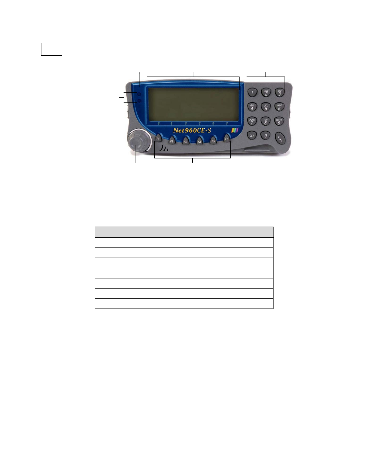
Alert LEDs
Customized Front
Panel Label
Terminal Display
Alpha-numeric
Keypad
Function KeysControl Knob
Figure 1: NET-960CE-S Standard Model – Front Panel Components
The table that follows lists the NET-960CE-S standard model Front Panel
components and refers you to their descriptions in this manual.
Table 1: NET-960CE-S – Front Panel with a link to component description
Net-960CE-S Components
Terminal Display, page 24
Customized Front Panel Label, page 24
Keyboard (Alpha-numeric Keypad and Function Keys), page 25
Control Knob, page 24
Alert LEDs, page 25
External Display, page 26
Voice Options, page 26
Page 15
Introducing the Net-960CE-S
Net-960CE-S MDT Hardware Guide
F2 F7 F1
Alert
F2 F7 F1
Alert
F2 F7 F1
F2 F7 F1
Alert
Alert
LEDs
LEDs
LEDs
LEDs
Pinhole
Pinhole
Pinhole
Pinhole
Function
Function
Function
Function
Keys
Keys
Keys
Keys
Figure 2: NET-960CE-S Screenless Model – Side Panel
The table that follows lists the NET-960CE-S screenless model Side Panel
components and refers you to their descriptions in this manual.
Table 2: NET-960CE-S – Side Panel with a Link to Component Description
Net-960CE-S Components
Function Keys, page 25
15
Alert LEDs, page 25
Page 16
The Net-960CE-S Device
16
Net-960CE-S MDT Hardware Guide
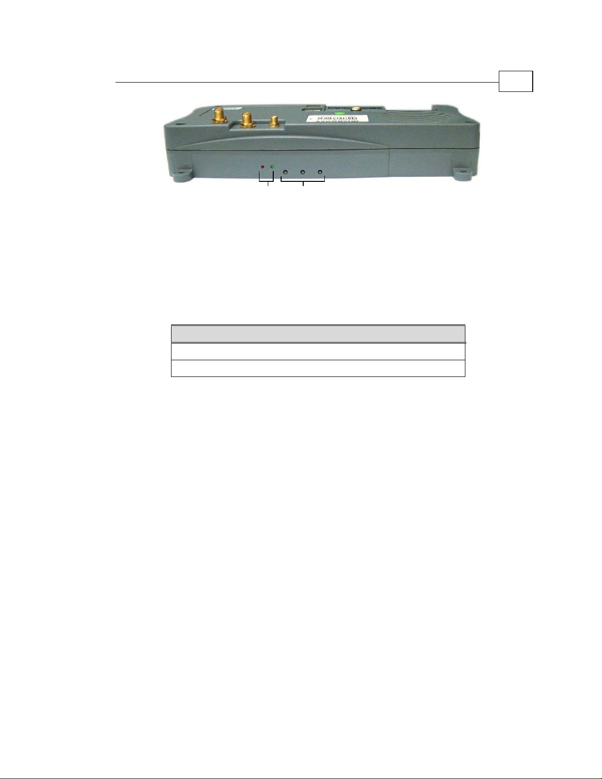
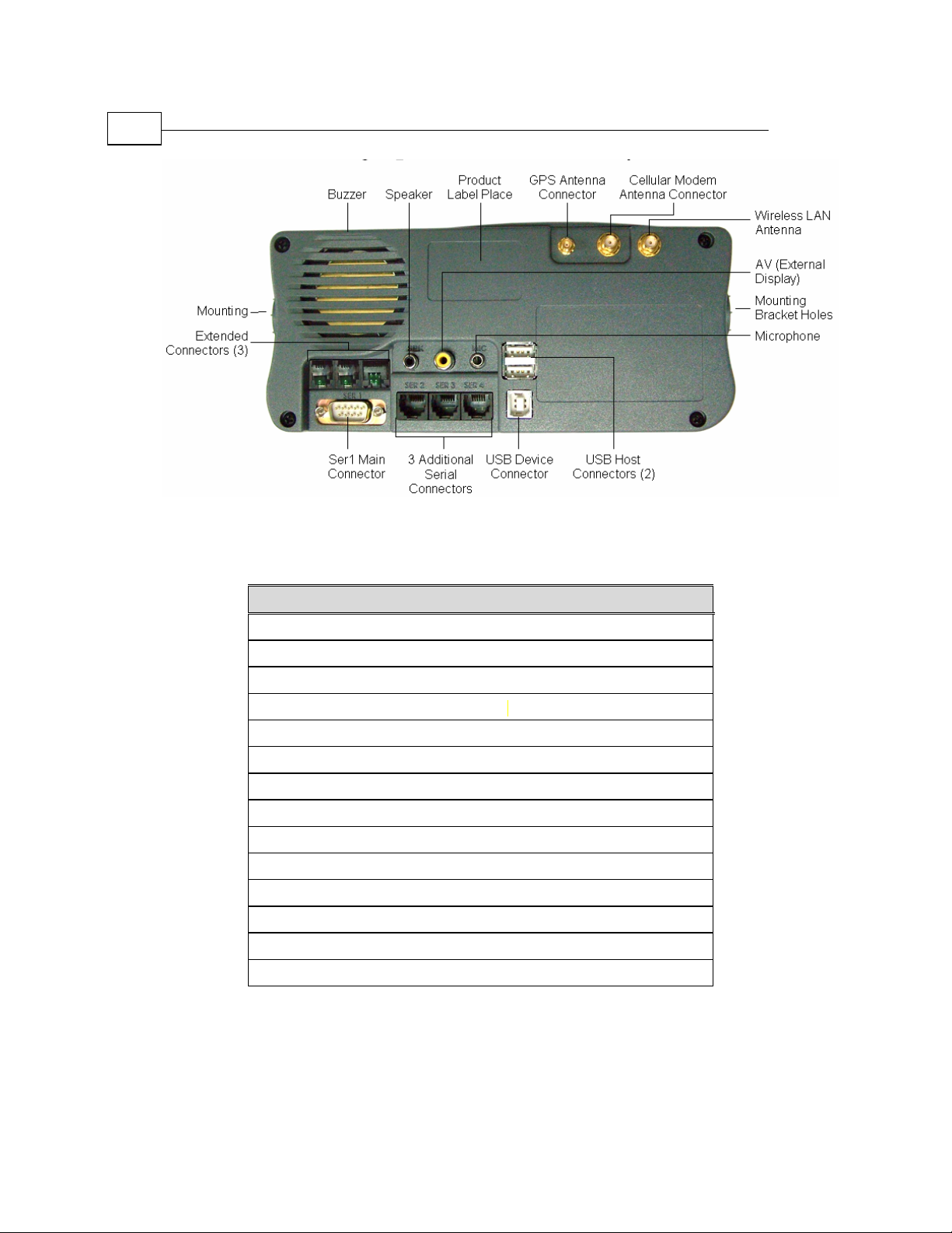
Figure 3: NET-960CE-S – Back Panel Components
Table 3: NET-960CE-S – Back Panel with a Link to Component Description
Net-960CE-S Component
Product Label
GPS Antenna Connector, page 54
Cellular Modem Antenna Connector, page 54
Wireless LAN Antenna Connector, page 55
USB Host Connectors, page 50
USB Device Connector, page 49
SER1 Main Connector, page 43
Three Additional Serial Connectors SER2, SER3 and SER4, page 45
AV (External Display), page 56
Microphone, page 56
Buzzer, page 26
Speaker, page 55
Extended Connectors EXT1, EXT2 and EXT3, page 51
Mounting Bracket Holes, page 59
Page 17
Introducing the Net-960CE-S
Net-960CE-S MDT Hardware Guide
17
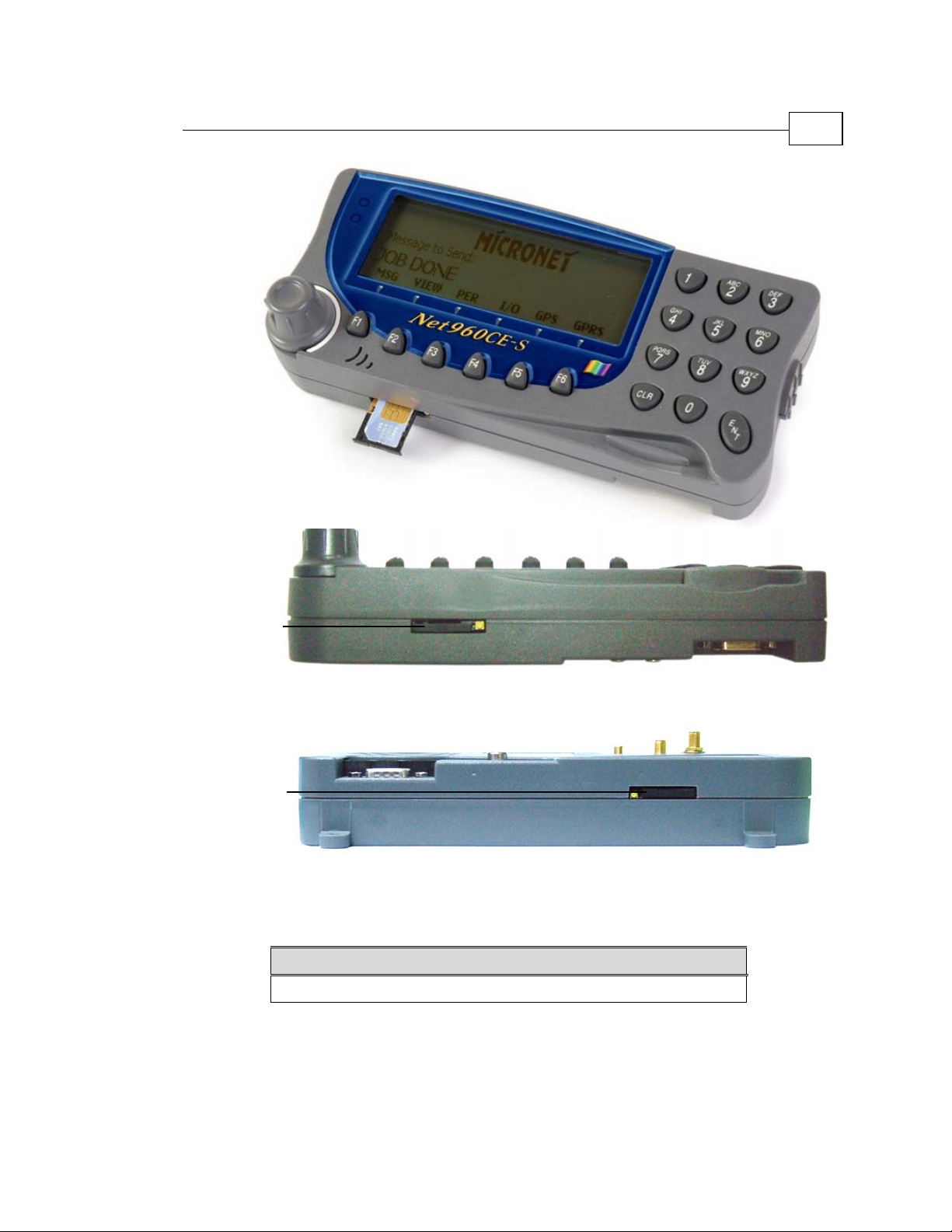
SIM Card SlotSIM Card SlotSIM Card SlotSIM Card Slot
SIM Card SlotSIM Card Slot
Figure 4: NET-960CE-S Standard Model – Bottom Panel
Figure 5: NET-960CE-S Screenless Model – Side Panel
Table 4: NET-960CE-S – Bottom Panel with a Link to Component Description
Net-960CE-S Component
SIM Card Slot, page 56
Page 18

The Net-960CE-S Device
18
Net-960CE-S MDT Hardware Guide
5Chapter 2
Net-960CE-S
Technical and
Functional
Description
About This Chapter
This chapter provides a table showing the Net-960CE-S specifications,
which is followed by sections that provide more detailed descriptions of
each of the Net-960CE-S features.
Page 19

Net-960CE-S Technical and Functional Description
Net-960CE-S MDT Hardware Guide
Net-960CE-S MDT – Specifications
The left column of the following table describes the basic configuration of
Net-960CE-S MDT. The right column shows the optional additions to this
basic configuration that can be ordered from Micronet at additional cost.
Table 5: Basic Configuration and Options
Basic Configuration and Options
Basic Configuration Options
Operating System:
Windows CE 4.2 .NET CF 1.0
Core license.
Development Environment and Tools:
Full Micronet SDK for Microsoft eMbedded
Visual C++ 4.0 and Visual Studio .NET
environments
CPU:
Motorola (DragonBall)
MC9328MXL 200MHz
ARM9, high performance 32-bit RISC engine
RTC:
Car battery backed up Real Time Clock
System and Application Memory:
RAM: 64MB
Flash: 32MB
Graphic Display:
Monochrome LCD, FSTN technology,
contrast ratio of 7:1,
Multilevel LED backlight
External Display Interface:
*
Windows CE 4.2 .NET CF 1.0
Professional license.*
DiskOnChip: 1 GB
Screenless option serves as an
under-dashboard MDT model.
Standard AV interface for external color display
support
External
from a third party
7" Color Display with touch screen
19
*
For a description of supported operating system components, see the Net-960CE-S
Operating System Spec
at
http://www.micronet.co.il/product.asp?secID=3&prodID=193
Page 20

Net-960CE-S MDT – Specifications
20
Net-960CE-S MDT Hardware Guide
Keys:
Unique control knob (Encoder switch)
12 Alpha-numeric and 6 function keys
(Elastomer)
Backlight for all keys
Alert Indications:
Two colored LEDs
Buzzer (with programmable frequency and
duration)
Serial Communication Ports:
Four RS232 communication ports including
one pair of H/W hand-shake control signals
Control I/0 Signals:
Two automotive inputs signals with counter
functionality and One O/C output
USB:
One USB 1.1 Device port supports full-speed
(12 Mbit/s), for development and debugging
GPRS modem:
GPS module:
Options Basic Configuration
For the screenless model, three pinhole function
buttons on the top side of the MDT (which can
be pressed by inserting the tip of a pen or the
end of an open paperclip)
Three RS232 communication ports including
one pair of H/W hand-shake control signals, and
one SAE J1708 port
Three automotive inputs signals with counter
functionality and two O/C outputs
(When using integrated GPRS&GPS
configuration)
Two USB 2.0 host ports supports full-speed
(12 Mbit/s) and low-speed (1.5 Mbit/s) for
keyboards, touch screen and storage dongle
support
Motorola quad band G24
850/900/1800/1900MHz, multi slot class 10,
internally connected to COM port 1 – with voice
support (requires external speaker and
microphone)
SIM Card access protection sticker
Trimble Lassen iQ 12 satellites, sensitive mode,
internally connected to COM port 2
Wireless LAN:
IEEE 802.11 standard at 2.4GHz frequency
band. 802.11b and 802.11g protocols
Bluetooth:
Specifications version 2.0 + EDR Class 1 power
level
Page 21

Net-960CE-S Technical and Functional Description
Net-960CE-S MDT Hardware Guide
21
Options Basic Configuration
Audio Codec:
For system sound and GSM voice support
(requires external speaker)
CANBus controller:
Power:
External power directly from vehicle's battery:
8V-30V DC
Power off: Software controlled
Power on: By key press or input signal
(ignition or VLU)
Watchdog:
Hardware and software watchdog mechanism
Environment:
Operating: -20°C to +70°C (-4°F to +158°F)
Storage: -20°C to +80°C (-4°F to +176°F)
Physical Dimensions:
Length: 200mm/7.87”
Width: 82mm/3.22”
Depth: 38mm/1.5”
Weight: 390gr./13.8Oz. (Basic configuration)
Protective Back-Cover:
Private Label:
I/O Signals & Peripherals Support:
Two analog inputs
One high speed digital counter
Dedicated port - Dallas ID button reader
Dedicated port - Swipe card reader tracks 1&2
or RFID clock and data interface
V2.0B, 1 Mbit port
Built-in GSM/GPRS module:
Operating: -20°C to +60°C (-4°F to +140°F)
Storage: -20°C to +80°C (-4°F to +176°F)
Protects back panel cables and outputs from
tampering
Customers may design their own front panel
label. Micronet will produce and supply the MDT
with the customized label.
Page 22

Computer Environment
22
Net-960CE-S MDT Hardware Guide
Computer Environment
CPU: Motorola (Dragon Ball), MC9328MXL 200MHz, ARM9,
high performance 32-bit RISC engine.
Development Environment and Tools: Full Micronet SDK.
Operating System: Windows CE .NET 4.2 is provided with its Core
license and provides the option for a Professional license at additional cost.
For a description of supported operating system components go to the
Net-960CE-S Operating System Spec at
http://www.micronet.co.il/product.asp?secID=3&prodID=193.
System and Application Memory
RAM/SDRAM
The Net-960CE-S provides 64 MB of SDRAM, which is partially allocated
for system and application usage.
When using the Windows CE .NET 4.2 Core license, approximately 16 MB
of SDRAM memory is allocated for system and the remainder is allocated
for application usage.
When using the Windows CE .NET 4.2 Professional license, approximately
27 MB of RAM memory is allocated for system and the remainder is
allocated for application usage.
Flash Memory
The Net-960CE-S provides 32 MB of Flash Memory, which can be used to
store the Net-960CE-S application and any other required files (such as
transactions) and programs that need to be stored permanently.
When using the Windows CE.NET 4.2 Core license, approximately 16 MB
of Flash memory is allocated for system usage and the remainder is
allocated for storage.
Page 23

Net-960CE-S Technical and Functional Description
Net-960CE-S MDT Hardware Guide
When using the Windows CE .NET 4.2 Professional license, approximately
27 MB of Flash memory is allocated for system usage and the remainder is
allocated for storage.
Optional DiskOnChip
An optional 1 GB internal DiskOnChip can be provided for additional
permanent storage of large databases.
External Mass Storage
The terminal supports standard external mass storage dongles through the
USB Host port.
NOTE:
In order to avoid loss of data, it is recommended that you implement the
following memory management techniques:
• Do not connect the terminal power to the ignition switch signal in order to
prevent uncontrolled power cut offs. Connect the terminal power directly to
the car battery and the ignition switch signal to one of the terminal inputs.
When the ignition switch signal has been powered off, use the shutdown
function to power off the terminal, ensuring that all files and sessions have
first been closed.
• Use the RAM storage for temporary files that are frequently updated.
• Ensure that you close all files that are not currently being used.
• When using extended permanent storage, such as DiskOnChip or USB,
saving the application executables in the terminal flash memory and the
data on the extended storage is the best way to protect your data.
23
Real Time Clock (RTC)
The terminal provides a hardware Real Time Clock that operates
continuously even when the terminal is powered off, but still connected to
the car battery. This option also provides the ability to power on the
terminal according to a predefined alarm.
Page 24

User Interface Options
24
Net-960CE-S MDT Hardware Guide
User Interface Options
The following sections describe the interface options for the Net-960CE-S.
Note that the terminal display, customized front panel label and control
knob do not exist for the screenless model.
Terminal Display
The Net-960CE-S provides a monochrome LCD on the front of the MDT
that can be used as primary or secondary user interface screen. This
terminal display can be used with or without the External Display,
described below, both of which can function independently. The terminal
display is based on FSTN technology, provides 240 x 64 pixels, dot pitch of
4.4 x 2.6 mm (.17" x .10"), has a contrast ratio of 7:1 and four LED
backlight levels.
Customized Front Panel Label
Micronet provides the option to print a customized front panel label,
according to your specifications. Micronet will provide the graphic files
and the size specifications to enable you to create your own branding for
the terminal's front panel. This is subject to an additional charge per unit,
based on quantity. Once printed, Micronet will store the labels and use
them for orders placed for this product.
Control Knob
The Net-960CE-S provides a unique control knob (encoder switch), which
enables the control of either the terminal display and/or the external display
as determined by the application. The control knob is backlit and provides
audio feedback. This feature is especially suited for application menu
selection or scrolling through lists. This control knob provides three control
operations as follows: right (Down key), left (Up key) and push (Space
key).
Page 25

Net-960CE-S Technical and Functional Description
Net-960CE-S MDT Hardware Guide
Keyboard
Standard Model
The Net-960CE-S standard model (with screen) provides twelve
alpha-numeric and six programmable functional keys (Elastomer). All these
keys are backlit, with four levels of programmable illumination, and
provide audio feedback. Functional key locations are strategically placed
under the terminal display to enable the application to utilize them as a
programmable menu.
Screenless Model
The screenless model provides three pinhole function buttons with audio
feedback, that can be used for reset and system management for application
configuration.
25
For both models, an external
be connected to terminal through USB host port.
(3rd party) full USB compliant keyboard can
Alert LEDs
The Net-960CE-S provides two colored LED Alert Indications, one green
and one red, both which can blink.
Page 26

External Display
26
Net-960CE-S MDT Hardware Guide
External Display
The Net-960CE-S provides the option of an external color screen
connection (via Standard AV interface) enabling a second external
party) screen. For this purpose, Net-960CE-S can interface with any
standard, automotive grade, color display (generally available with or
without touch screen capability). This special screen configuration is ideal
for use with the screenless model and also for backseat passengers, for
extra navigational comfort and for other interactive on-the-go applications.
This external screen can be used as primary or secondary user interface
screen with or without the terminal display described above, both of which
can function independently. This external screen can provide touch
functionality connected through the USB host port of the Net-960CE-S.
Voice Options
(3rd
Buzzer
The Net-960CE-S provides an internal buzzer for indicating alerts with
programmable frequency and duration. Two volume levels are available.
Audio Codec
The Net-960CE-S provides an Audio Codec that can sound prerecorded
system messages (WAV files). This function requires the connection of an
external speaker. For more details refer to the External Speaker Connector
on page
55.
Page 27

Net-960CE-S Technical and Functional Description
Net-960CE-S MDT Hardware Guide
Communication
Serial Communication
The Net-960CE-S provides four serial communication ports for serving
various internal and external devices.
Each of these ports provides different options, as described in the sections
that follow. Chapter 4, Net-960CE-S Signal Maps, page
function of each signal of each Net-960CE-S port.
Serial Port 1 (SER1 Connector)
Generally, Serial Port 1 functions as a main system serial port for modem
communication. It provides a maximum Baud rate of 115,200bps and one
pair of communication control handshake signals (CTS/RTS). It can
provide either of the following two functions, as determined by factory
settings:
42, describes the
27
• Basic Terminal Configuration (SER1 Connector): In its basic
terminal configuration, Serial Port 1 is physically connected to the
SER1 connector and provides the control signal CTS/RTS.
NOTE:
Within the framework of OEM customization, additional RS232 level control
signals can be provided. For more information on this subject, please contact
Micronet sales support.
Backward compatibility: If your are installing the Net-960CE-S as an
upgrade to an existing Micronet device (such as the Net-960EX) and want to
connect to the same external devices, please refer to Micronet sales support.
• Internal Cellular Modem Terminal Configuration: In this
configuration, Serial Port 1 is connected internally to the cellular
modem and is not connected to the external serial connector. Refer to
the Cellular Communication section on page
(SER1 Connector) section, on page
43 for more details.
31 and in the Serial Port 1
Page 28

Communication
28
Net-960CE-S MDT Hardware Guide
Serial Port 2 (SER2 Connector)
Serial Port 2 is connected to the SER2 connector. It provides a maximum
Baud rate of 115,200bps and one pair of communication control handshake
signals (CTS/RTS).
When using the internal GPS option, the Serial Port 2 can switch between
the following two functions as determined by the Net-960CE-S's
programmable software.
• SER2 (default setting): When the Serial Port 2 is set by the
application to connect to the SER2 port, it serves as a standard serial
communication port for connection to external devices.
• GPS Receiver: When the Serial Port 2 is set by the application to
connect internally to the GPS Receiver, it can receive GPS data, which
makes it especially suitable for navigation applications and traffic
reports. Refer to the GPS Receiver section on page
This means that upon software request, Serial Port 2 can switch between
the connection to the SER2 connector and the connection to the internal
GPS Receiver.
page
45.
32 for more details.
For further details refer to the SER2 Connector section, on
Page 29

Net-960CE-S Technical and Functional Description
Net-960CE-S MDT Hardware Guide
Serial Port 3 (SER3 Connector)
Serial Port 3 is connected to the SER3 connector. It can provide either of
the following two features, as determined by factory settings.
• RS232 (maximum Baud rate: 115,200bps) with one pair of
communication control handshake signals (CTS/RTS).
• SAE J1708 (Baud rate: 9600bps only).
For further details refer to the SER3 Connector section, on page 46.
Serial Port 4 (SER4 Connector)
Serial Port 4 can provide either of the following two functions, as enabled
by the Net-960CE-S's programmable software:
• Default Serial Port 4 Configuration: In this configuration, Serial
Port 4 serves as a standard serial communication port for connection to
external devices. Its communication standards are RS232 (maximum
Baud rate: 115,200bps) with one pair of communication control
handshake signals (CTS/RTS).
29
• Internal Bluetooth Module Option: In this option, Serial Port 4 is
connected internally to the Bluetooth modem and is not connected to
the external serial connector.
For further details, refer to the SER4 Connector section, on page
48.
Page 30

Communication
30
Net-960CE-S MDT Hardware Guide
USB Device Port
The Net-960CE-S provides a USB device port to enable connection to
devices that have a USB host port, such as laptops. This port is especially
useful for interacting with the Net-960CE-S by downloading firmware,
applications and configurations. It can also be used for software and
technical support.
This functionality complies with Universal Serial Bus Specification
Rev. 1.1 and supports full-speed (12 Mbit/s).
USB Host Ports
The Net-960CE-S optionally provides two USB 2 host ports connected
through a double USB host connector. These ports enable the connection to
devices that have a USB device interface, such as USB printers, USB
keyboards, USB memory storage devices and so on. For further details,
refer to the USB Host Connector section, page
50.
This functionality complies with Universal Serial Bus Specification
Rev. 2.0 and supports full-speed (12 Mbit/s) and low-speed (1.5 Mbit/s).
CANBus Port
The Net-960CE-S optionally provides a CANBus port that enables the
connection of a variety of vehicle peripherals through the EXT1 connector,
such as the vehicle's computer, vehicle's sensors and so on.
details, refer to the EXT1 Connector section, page
The provided CANBus V2.0B (a 1 Mbit port) supports the following
functionality:
• 0 - 8 byte length in the data field
• Standard and extended data and remote frames
• Two receive buffers with prioritized message storage
• Six 29-bit filters
• Two 29-bit masks
• Three transmit buffers with prioritization and abort features
51.
For further
Page 31

Net-960CE-S Technical and Functional Description
Net-960CE-S MDT Hardware Guide
Wireless Communication
• Cellular Communication, below
• GPS Receiver, page
• Wireless LAN, page
32
33
31
• Bluetooth Communication, page
33
Cellular Communication
As determined by factory settings, the Net-960CE-S can optionally provide
an internal GSM/GPRS Cellular Modem to enable communication
functionality between the terminal and any server or back-office.
The Motorola G24 cellular modem that is optionally provided with the Net960CE-S has the following features:
• Quad band 850/900/1800/1900 MHz
• GPRS Multi slot class 10
• MO/MT SMS
• FAX
• VOICE
The internal modem option requires an external antenna connection and a
SIM card.
WARNING
The wireless LAN antenna connector and the GPRS antenna connector on the back
panel of the Net-960CE-S are both SMA connectors. Ensure that you connect the
correct antenna to the correct connector.
Voice calls can be supported and require an external speaker and a
microphone connection, as shown on page
NOTE:
In this configuration, Serial Port 1 is connected internally to the cellular modem and
is not connected to the external SER1 connector.
55 and 56.
Page 32

Communication
32
Net-960CE-S MDT Hardware Guide
The bottom of the Net-960CE-S provides a SIM card slot and the back
panel of the Net-960CE-S will have a cellular modem antenna connector, as
shown on page
Connector section, page
GPS Receiver
As determined by factory settings, the Net-960CE-S optionally provides an
internal GPS receiver especially suited for navigation applications and
traffic reports.
Serial Port 2 can switch between the internal GPS Receiver and the external
SER2 connector (page
The Trimble Lassen iQ module is provided with the following features:
• 12-channel simultaneous operation
• Horizontal Accuracy: <5 meters (50%), <8 meters (90%)
• Altitude Accuracy: <10 meters (50%), <16 meters (90%)
17. For further details, refer to the Cellular Modem Antenna
54.
28 and 45) upon software request.
• Supports NMEA 0183, TSIP, TAIP protocols
The GPS Receiver requires an external GPS antenna connection. The GPS
antenna receives the GPS satellite signals and passes them to the GPS
Receiver. The GPS signals are spread spectrum signals in the 1575 MHz
range and do not penetrate conductive or opaque surfaces. Therefore, the
antenna must be located outdoors with a clear view of the sky. For further
details, refer to the GPS Antenna Connector section, page
WARNING!
When magnetic-mount or permanent-mount GPS antennas are installed on a metal
source for prolonged periods, care must be taken to insulate the antennas in order
to prevent galvanic corrosion or electrical damage.
54.
The back panel of the Net-960CE-S provides a GPS antenna connector, as
shown on page
16.
Page 33

Net-960CE-S Technical and Functional Description
Net-960CE-S MDT Hardware Guide
Wireless LAN
As determined by factory settings, the Net-960CE-S optionally provides an
internal Wireless Local Area Network (IEEE 802.11) module especially
suited to high-speed data transfer over the air, when the Wireless LAN
hotspots infrastructure is provided. For applications that require large scale
data transactions, the Wireless LAN option is the most economical way to
implement the solution (as wireless LAN data transactions are free).
The Onboard Wireless LAN module is provided with the following
features:
• Specification Compliance: IEEE 802.11b/g standard protocol
(CSMA/CA)
•
Frequency Range: 2.412 Ghz~2.484 Ghz
• Data Baud Rate: 54 Mbps
The Wireless LAN option requires an external antenna connection.
33
WARNING
The wireless LAN antenna connector and the GPRS antenna connector on the back
panel of the Net-960CE-S are both SMA connectors. Ensure that you connect the
correct antenna to the correct connector.
Bluetooth Communication
As determined by factory settings, the Net-960CE-S optionally provides an
internal Bluetooth Class 1 module with an internal antenna, which can
communicate with a variety of peripherals, such as printers, PDAs, laptops,
cellular phones and so on.
This functionality complies with Bluetooth specifications version 2.0 +
EDR Class 1 power level.
NOTE:
In this configuration, Serial Port 4 is connected internally to the Bluetooth module
and is not connected to the external serial connector. For further details refer to the
SER4 Connector section, on page 48.
Page 34

Control Signals
34
Net-960CE-S MDT Hardware Guide
Control Signals
As determined by factory settings, the Net-960CE-S optionally provides a
variety of digital inputs and outputs and two analog inputs that can be used
to connect devices and sensors at a variety of voltage levels.
Digital Signals
Several digital control input of the terminal can provide counter
functionality of up to 1 KHz.
SER1 Control Signals
Depending on the terminal configuration, the SER1 connector can provide
up to three control inputs with counter functionality and up to two control
outputs at automotive voltage level. These I/Os can be used for the
monitoring and operating of external devices.
For further details about voltage parameters and signal configuration, refer
to the Serial Port 1(SER1 Connector) section on page
27.
EXT Control Signals
As determined by factory settings, the EXT connectors optionally provide a
variety of inputs and outputs in a variety of voltage levels. The EXT
connectors can serve dedicated ports for extended device functionality or
they can be used as regular control signals.
The EXT1 connector provides one regular digital input, which can be used
as a regular control input or as a high speed counter input of up to 1 MHz.
For further details, refer to the EXT1 Connector section, page
The EXT3 connector provides five digital input signals with counter
functionality. These signals also serve the magnetic cards reader interface,
and cannot be used as input signals when a magnetic cards reader is
connected.
For further details, refer to the EXT3 Connector section, page
51.
53.
Page 35

Net-960CE-S Technical and Functional Description
Net-960CE-S MDT Hardware Guide
Analog Signals
As determined by factory settings, the EXT2 connector optionally can
provide two analog inputs with a voltage range of 0 to 30V to monitor
compatible vehicle peripherals. For further details, refer to the EXT2
Connector section, page
52.
Peripheral Support – Dedicated Ports
Magnetic Card Reader Port
As determined by factory settings, the Net-960CE-S optionally provides a
magnetic card reader (track 1 and track 2) clock and data interface port
connected through the EXT3 connectors that can be used for a variety of
applications, such as to read driver identification or credit card transactions.
For further details, refer to the Ext3 Connector section, page
53.
35
Memory ID Button Reader Port
As determined by factory settings, the Net-960CE-S optionally provides a
1-Wire interface port (through the EXT2 connector), which provides
control, signaling and power over a single-wire connection. By connecting
an optional touch probe accessory, Dallas ID Memory Buttons can be used
as a means for identification and authorization control. For further details,
refer to the EXT2 Connector section, page
52.
Page 36

Overview
36
Net-960CE-S MDT Hardware Guide
About This Chapter
This chapter describes the various aspects of Net-960CE-S power, such as
power management, battery voltage, peripheral voltage supply and power
down control.
6Chapter 3
Net-960CE-S
Power
Overview
The Net-960CE-S power is drawn directly from the vehicle's 12V/24V DC
battery, and provides intelligent power management options that reduce
drain on the vehicle’s main battery.
The Net-960CE-S also enables the control of external peripheral power,
backlight and power lines for internal modules.
Both internal and external devices can be turned on and off, as required.
Page 37

Net-960CE-S Power
Net-960CE-S MDT Hardware Guide
Battery Voltage Input
Net-960CE-S power is connected through the SER1 connector pin 8 (+)
and pin 5 (-). The nominal voltage supply for the Net-960CE from the
vehicle’s battery is 12 or 24V. The operating range is between 8 and 30V.
The terminal must be connected directly to the vehicle's battery or VLU
(Vehicle Location Unit).
WARNING!
Do not connect the terminal power to the ignition switch signal in order to prevent
uncontrolled power cut offs, which may have a detrimental affect on the operating
system. Connect the terminal power directly to the car battery and the ignition switch
signal to one of the terminal inputs. When the ignition switch signal has been
powered off, use the shutdown function to power off the terminal, ensuring that all
files and sessions have first been closed.
The Net-960CE-S has no internal fuse, and therefore its connected to the
vehicle's power source line should be protected by a 10A fuse.
Additionally, a 4A fuse should be added to the power cable with an inline
fuse holder for HHC/HHD blade-type fuses.
37
Table 6: Terminal Power Consumption
Operation Mode Current Consumption
Power Off
Idle
(no active application)
Active
(without wireless communication)
Run
(with wireless communication)
~ 1mA
~ 120mA
~ 400mA
~ 750mA
Page 38

Power Management
38
Net-960CE-S MDT Hardware Guide
Power Management
When connected to the car battery, the Net-960CE-S terminal can only be
powered down by software control. The applications can be designed to
power down the terminal when a signal drop is detected on the input lines.
For example, when the ignition is turned off or according to AVL request.
The Net-960CE-S provides three input lines that turn on the terminal upon
signal rise. For example, when the ignition is turned on.
In addition, pressing the control knob also turns on the terminal.
A Real Time Clock option also provides the ability to power on the
terminal according to a predefined alarm.
NOTE:
Within the framework of OEM customization, one of these input lines can be factory
set not to turn on the terminal.
The terminal also has the ability to control the power supply to internal
terminal modules.
Watchdog
The Net-960CE-S provides an intelligent watchdog module that provides
various options for programming the terminal to automatically reset. For
example, after an error and a timeout.
Page 39

Net-960CE-S Power
Net-960CE-S MDT Hardware Guide
Manual Reset and Boot Mode
The standard model of the Net-960CE-S terminal can be reset by
simultaneously pressing the 5, 8 and F1 keys.
Simultaneously press the
Simultaneously press the
5, 8 and F1 buttons to
5, 8 and F1 buttons to
The screenless model of the Net-960CE-S terminal can be reset by
simultaneously pressing the F1 and F2 keys.
reset
reset
39
Simultaneously press the
Simultaneously press the
F1 and F2 buttons to
F1 and F2 buttons to
reset
reset
NOTE:
It is highly recommended not to use the Manual Reset operation. This operation
should only be activated by a technician.
This operation should not be activated while the application is running or saving
data to the FLASH storage or DiskOnChip, as it may damage FLASH sectors.
Page 40

Peripherals Voltage Supply
40
Net-960CE-S MDT Hardware Guide
Peripherals Voltage Supply
The Net-960CE-S provides programmable operating voltage of 5V for
external peripheral devices. This supplied voltage is filtered and stabilized,
thus eliminating battery voltage fluctuations and noise. All voltage supply
lines are protected and current limited.
This signal is simultaneously connected to the Power Out pins of all SER
and EXT connectors. Switching this signal on/off causes the
enabling/disabling of all connected peripherals. A total of 700mA of
aggregated power can be supplied by the terminal to all connected
peripherals.
Page 41

Net-960CE-S Power
Net-960CE-S MDT Hardware Guide
41
Page 42

Peripherals Voltage Supply
42
Net-960CE-S MDT Hardware Guide
About This Chapter
This chapter provides various tables mapping the power and
communication signals of the Net-960CE-S ports. The options and
functionality of each of these ports are described in detail in Chapter 2,
Net-960CE-S Technical and Functional Description on page
7Chapter 4
Net-960CE-S
Signal Maps
18.
Some of the connectors described in this chapter, such as the SER1
connector, have two factory configurable options, each of which have a
different signaling map. In these cases, two signaling map tables are
provided. All pins are protected against electrostatic discharge (ESD
protected).
The following lists some of the abbreviations used in the signal descriptions
of this chapter:
I Input signal
O Output signal
B Bus signal
V Voltage signal
G Ground
Page 43

Net-960CE-S Signal Maps
Net-960CE-S MDT Hardware Guide
43
Serial Port 1 (SER1 Connector)
Connector type: D-type 9-pin Male.
Table 7: (SER1) Connector Pinout for Basic Configuration
Pin Signal Type Function Specifications
1 SER1_IN1
(DSR)
2 RXD (COM1) I Receive Data
3 TXD (COM1) O Transmit Data EIA-RS232 level
4 RTS (COM1) O Request To Send EIA-RS232 level
5 GND G
6 CTS (COM1) I Clear To Send EIA-RS232 level
7 SER1_OUT2
(DTR)
8 +VIN V
9 SER1_IN3
(RI)
I
Control Input/
Counter
MDT Power
Supply
Ground
O Control Output Open Collector
MDT Power
Supply
Voltage
I
Control Input/
Counter
Typical Min Max
Input Low: V
Input High: V
Frequency: Up to 1KHz
EIA-RS232 level
Max. switchable current = 300mA
Max. switchable voltage = +V
Max. saturation voltage = 0.6V
Typical Min Max
+12V-24V
Typical Min Max
Input Low: V
Input High: V
Frequency: Up to 1KHz
IL 0V -30V 6V
IH 12V-24V +8V +30V
+8V +30V
IL 0V -30V 6V
IH 12V-24V +8V +30V
IN
Page 44

Serial Port 1 (SER1 Connector)
44
Net-960CE-S MDT Hardware Guide
NOTE:
Within the framework of OEM customization, DSR, DTR and RI communication
control signals can be provided instead of automotive control I/O.
Table 8: (SER1) Connector Pinout for Internal GPRS/GPS Configuration
Pin Signal Type Function Specifications
1
SER1_IN1
2 NC Not connected
3 NC Not connected
4 SER1_OUT1 O Control Output Open Collector
5 GND G
6 SER1_IN2 I
7 SER1_OUT2 O Control Output Open Collector
8 +VIN V
9
SER1_IN3
I
Control Input/
Counter
MDT Power
Supply
Ground
Control Input/
Counter
MDT Power
Supply
Voltage
I
Control Input/
Counter
Typical Min Max
Input Low: V
Input High: V
Frequency: Up to 1KHz
Max. switchable current = 300mA
Max. switchable voltage = +V
Max. saturation voltage = 0.6V
Typical Min Max
Input Low: V
Input High: V
Max. switchable current = 300mA
Max. switchable voltage = +VIN
Max. saturation voltage = 0.6V
Typical Min Max
+12V-24V
Typical Min Max
Input Low: V
Input High: V
Frequency: Up to 1KHz
IL 0V -30V 6V
IH 12V-24V +8 V +30V
IN
IL 0V -30V 6V
IH 12V-24V +8V +30V
+8V +30V
IL 0V -30V 6V
IH 12V-24V +8V +30V
Page 45

Net-960CE-S Signal Maps
Net-960CE-S MDT Hardware Guide
45
Serial Port 2 (SER2 Connector)
Connector type: RJ12 6-pin female.
Table 9: (SER2) Connector Pinout for RS232 Configuration
Pin Signal Type Function Specifications
1 +5V_SW V
2
RTS
(COM2)
3
TXD
(COM2)
4
RXD
(COM2)
5
CTS
(COM2)
6 GND G Ground
O
O
I
I
Switched
5V Power
Out Pin
Request To
Send
Transmit
Data
Receive
Data
Clear To
Send
+5V±10%; 500mA max.
Note: This signal is simultaneously
connected to the Power Out pins of all SER
and EXT connectors. Switching this signal
on/off causes enabling/disabling of all
connected peripherals.
A total of 700mA can be supplied by the
terminal to all connected peripherals.
EIA-RS232 level.
EIA-RS232 level.
Note: This signal can be switched between
the internal GPS module and this
connector pin.
EIA-RS232 level.
Note: This signal can be switched between
the internal GPS module and this
connector pin.
EIA-RS232 level.
Page 46

Serial Port 3 (SER3 Connector)
46
Net-960CE-S MDT Hardware Guide
Serial Port 3 (SER3 Connector)
Connector type: RJ12 6-pin Female.
Table 10: (SER3) Connector Pinout for RS232 Configuration
Pin Signal Type Function Specifications
1 +5V_SW V
2
3
4
5
6 GND G Ground
RTS
(COM3)
TXD
(COM3)
RXD
(COM3)
CTS
(COM3)
O
O
I
I
Switched
5V Power
Out Pin
Request To
Send
Transmit
Data
Receive
Data
Clear To
Send
+5V±10%; 500mA max.
Note: This signal is simultaneously
connected to the Power Out pins of all SER
and EXT connectors. Switching this signal
on/off causes enabling/disabling of all
connected peripherals.
A total of 700mA can be supplied by the
terminal to all connected peripherals.
EIA-RS232 level
EIA-RS232 level
EIA-RS232 level
EIA-RS232 level
Page 47

Net-960CE-S Signal Maps
Net-960CE-S MDT Hardware Guide
47
Table 11: (SER3) Connector Pinout for J1708 Configuration
Pin Signal Type Function Specifications
1 +5V_SW V
Switched
5V Power
Out Pin
+5V±10%; 500mA max.
Note: This signal is simultaneously
connected to the Power Out pins of all SER
and EXT connectors. Switching this signal
on/off causes enabling/disabling of all
connected peripherals.
A total of 700mA can be supplied by the
terminal to all connected peripherals.
2
RTS
(COM3)
3 -IN (COM3) B
4
+IN
(COM3)
5
CTS
(COM3)
O
B
I
Request To
Send
J1708 Bus
Pin (-)
J1708 Bus
Pin (+)
Clear To
Send
EIA-RS232 level
SAE J1708 level
SAE J1708 level
EIA-RS232 level
6 GND G Ground
Page 48

Serial Port 4 (SER4 Connector)
48
Net-960CE-S MDT Hardware Guide
Serial Port 4 (SER4 Connector)
Connector type: RJ12 6-pin Female.
Table 12: (SER4) Connector Pinout for RS232 Configuration
Pin Signal Type Function Specifications
1 +5V_SW V
2
3
4
5
6 GND G Ground
RTS
(COM4)
TXD
(COM4)
RXD
(COM4)
CTS
(COM3)
O
O
I
I
Switched
5V Power
Out Pin
Request To
Send
Transmit
Data
Receive
Data
Clear To
Send
+5V±10%; 500mA max.
Note: This signal is simultaneously
connected to the Power Out pins of all SER
and EXT connectors. Switching this signal
on/off causes enabling/disabling of all
connected peripherals.
A total of 700mA can be supplied by the
terminal to all connected peripherals.
EIA-RS232 level
EIA-RS232 level
EIA-RS232 level
EIA-RS232 level
Page 49

Net-960CE-S Signal Maps
Net-960CE-S MDT Hardware Guide
Table 13: (SER4) Connector Pinout for Internal Bluetooth Configuration
Pin Signal Type Function Specifications
1 +5V_SW V
2 NC
3 NC
4 NC
5 NC
6 GND G Ground
Switched
5V Power
Out Pin
Not
connected
Not
connected
Not
connected
Not
connected
+5V±10%; 500mA max.
Note: This signal is simultaneously
connected to the Power Out pins of all SER
and EXT connectors. Switching this signal
on/off causes enabling/disabling of all
connected peripherals.
A total of 700mA can be supplied by the
terminal to all connected peripherals.
49
USB Device Connector
Connector type: USB Type B.
Table 14: (USB Device) Connector Pinout
Pin Signal Type Function Specifications
1 NC
2 D+ B USB Data (+)
3 D- B USB Data (-)
4 GND G Ground
Not
connected
Universal Serial Bus Specification
Rev 1.1.
Universal Serial Bus Specification
Rev 1.1.
Page 50

USB Host Connectors
50
Net-960CE-S MDT Hardware Guide
USB Host Connectors
Connector type: Double USB Type A.
Table 15: (USB Host Slot 1) Connector Pinout
Pin Signal Type Function Specifications
1 +5V V
2 D+ B USB Data (+)
3 D- B USB Data (-)
4 GND G Ground
5V Power Out
Pin
+5V±10%; 500mA max.
Note: A total of 700mA can be
supplied by the terminal to all
connected peripherals.
Universal Serial Bus Specification
Rev 2.
Universal Serial Bus Specification
Rev 2.
Table 16: (USB Host Slot 2) Connector Pinout
Pin Signal Type Function Specifications
1 +5V V
2 D+ B USB Data (+)
3 D- B USB Data (-)
4 GND G Ground
5V Power Out
Pin
+5V±10%; 500mA max.
Note: A total of 700mA can be
supplied by the terminal to all
connected peripherals.
Universal Serial Bus Specification
Rev 2.
Universal Serial Bus Specification
Rev 2.
Page 51

Net-960CE-S Signal Maps
Net-960CE-S MDT Hardware Guide
51
EXT1 Connector
Connector type: RJ11 4-pin Female.
Table 17: (EXT1) Connector Pinout
Pin Signal Type Function Specifications
1 CANBus H B
2 CANBus L B
3
EXT1_IN1 /
High Speed
Counter
Input
4 GND G Ground
I
CAN HighLevel Voltage
I/O
CAN LowLevel Voltage
I/O
Control Input/
High Speed
Counter
CANBus Specification V2.0B
CANBus Specification V2.0B
CMOS Level 3.3V. 5V tolerant
Min Max
Input Low: VIL 0V 0.8V
Input High: VIH 2.0V 5.5V
Internal Line Termination Resistor 10 ohm
Page 52

EXT2 Connector
52
Net-960CE-S MDT Hardware Guide
EXT2 Connector
Connector type: RJ11 4-pin Female
Table 18: (EXT2) Connector Pinout
Pin Signal Type Function Specifications
1 A/D Input1 I
2
IN / OUT / ID
Button Port
3 GND G Ground
4 A/D Input2 I
I/O
Analog Input
One-Wire
Interface.
(DALLAS ID
Button
Interface)
Port.
Analog Input
0V-30V max, 12k OHM
0V-30V max, 12k OHM
Page 53

Net-960CE-S Signal Maps
Net-960CE-S MDT Hardware Guide
53
EXT3 Connector
Connector type: RJ45 8-pin Female.
Table 19: (EXT3) Connector Pinout
Pin Signal Type Function Specifications
1 EXT3_IN1 I Control Input/Counter
2 EXT3_IN2 /
CARD DETECT
3 EXT3_IN3 /
CARD CLK 2
4 EXT3_IN4 /
CARD DATA 2
5 EXT3_IN5 /
CARD CLK 1
6 EXT3_IN6 /
CARD DATA 1
7 GND G Ground Input Low: VIL 0V 0.8V
8 +5V_SW V
* All pins are at 3.3V. 5V tolerant CMOS Level.
I
Control Input/
Card Detect (Card
Reader Port)/Counter
I
Control Input/
Clock Track 2 (Card
Reader Port)/Counter
I
Control Input/
Data Track 2 (Card
Reader Port)
I
Control Input/
Clock Track 1 (Card
Reader Port)/Counter
I
Control Input/Data
Track 1 (Card Reader
Port)
Switched 5V Power Out
Pin
Min Max
Input Low: VIL 0V 0.8V
Input High: VIH 2.0V 5.5V
Input Low: VIL 0V 0.8V
Input High: VIH 2.0V 5.5V
Input Low: VIL 0V 0.8V
Input High: VIH 2.0V 5.5V
Input Low: VIL 0V 0.8V
Input High: VIH 2.0V 5.5V
Input Low: VIL 0V 0.8V
Input High: VIH 2.0V 5.5V
Input Low: VIL 0V 0.8V
Input High: VIH 2.0V 5.5V
Input High: VIH 2.0V 5.5V
+5V±10%; 500mA max.
Note: This signal is simultaneously connected to
Power Out pins of all (SER) and (EXT)
connectors. Switching this signal on/off causes
enabling/disabling of all connected peripherals.
A total of 700mA can be supplied by the terminal
to all connected peripherals.
Page 54

r
GPS Antenna Connector
54
Net-960CE-S MDT Hardware Guide
GPS Antenna Connector
Connector type: MCX Female
GPS
Antenna
GPS Antenna Performance Recommendations: Active, 3.3 VDC
WARNING!
When magnetic-mount or permanent-mount GPS antennas are installed on a metal
source for prolonged periods, care must be taken to insulate the antennas in order
to prevent galvanic corrosion or electrical damage.
Cellular Modem Antenna Connector
Connector type: SMA Female
Cellular Modem
Antenna Connecto
Table 20: GSM/GPRS Antenna Performance Recommendations
Frequencies
TX 824 – 849 MHz GSM 850
RX 869 – 893 MHz
TX 880 – 915 MHz GSM 900
RX 925 – 960 MHz
TX 1710 – 1785 MHz DCS 1800
RX 1805 – 1880 MHz
TX 1850 - 1910 MHz PCS 1900
RX 1930 – 1990 MHz
Gain:
Impedance:
VSWR:
0 dBi (unity) gain or greater
50 Ohm
Typical: 1.5:1
Worst Case: 2.5:1
Page 55

Net-960CE-S Signal Maps
Net-960CE-S MDT Hardware Guide
WARNING
The wireless LAN antenna connector and the GPRS antenna connector on the
back panel of the Net-960CE-S are both SMA connectors. Ensure that you
connect the correct antenna to the correct connector.
55
Wireless LAN Antenna Connector
Connector type: SMA Female
Wireless LAN
Antenna Connector
Table 21: Wireless LAN Antenna Performance Recommendatio ns
Frequency:
Gain:
Impedance:
VSWR:
2400-2500 MHz
2 dBi gain or greater
50 Ohm
Typical: 1.5:1
WARNING
The wireless LAN antenna connector and the GPRS antenna connector on the
back panel of the Net-960CE-S are both SMA connectors. Ensure that you
connect the correct antenna to the correct connector.
External Speaker Connector
External
Speaker
Connector type: 3.5mm Mono Jack Female
Mono loudspeaker output: 1.1 W, 4-8 OHM
Page 56

AV Connector
56
Net-960CE-S MDT Hardware Guide
AV Connector
Connector type: RCA Phono Jack (Yellow) Female
AV Connector
Composite Video
PAL (ITU-R624-3) System
NOTE:
The quality of the cable connected to the external display may affect the quality of
the picture. Use a braid and foil cable from a reputable company. Avoid the usage of
poor quality cables.
Microphone Connector
Connector type: 2.5mm Mono Jack Female
Microphone Connector
Microphone performance recommendations:
• Electret microphone
• 2.2V Feeding source
• Resistance up to 2K
SIM Card Connector
SIM Card Connector
SIM Card
Standard SIM card connector type
32K SIM
1.8V / 3.0V
Page 57

Net-960CE-S Signal Maps
Net-960CE-S MDT Hardware Guide
57
Page 58

SIM Card Connector
58
Net-960CE-S MDT Hardware Guide
About This Chapter
This chapter describes the installation procedure of the Net-960CE-S
device, including bracket mounting and electrical installation, as follows:
8Chapter 5
Net-960CE-S
Installation
1 Determine the optimal positioning of the Net-960CE-S in the vehicle to
enable access and a clear view.
2 Perform the mechanical installation of the Net-960CE-S on the
mounting bracket, as described on page
3 Perform the electrical preparation of the external devices to suit the
Net-960CE-S communication cables, as described on page
4 Connect all external devices and antennas.
5 Connect the Net-960CE-S's power.
59.
61.
Page 59

Net-960CE-S Installation
Net-960CE-S MDT Hardware Guide
59
Mechanical Installation
Mounting the Net-960CE-S MDT Standard Model
The Net-960CE-S is supplied with a mounting bracket with eight 6.3mm
(0.25”) holes prepared in advance for attachment to the vehicle’s
dashboard.
1 Affix the bracket in the desired position using as many screws as
required.
2 Align the round rubber mount on the right and left sides of the
Net-960CE-S with one of the three holes provided on the sides of the
bracket. Both sides should be aligned with the same hole, meaning
either the top, middle or bottom hole on each side.
3 Attached the rubber side screws from the outside of each side of the
bracket so that it goes through the bracket hole and screws into the
rubber mount, which is attached to the Net-960CE-S. Screw it in
firmly, but do not over-tighten.
Figure 6: Mechanical Installation – Standard Model
Page 60

Mechanical Installation
60
Net-960CE-S MDT Hardware Guide
Mounting the Net-960CE-S MDT Screenless Model
The Net-960CE-S screenless model has four tabs for the insertion and
tightening of screws.
NOTE:
Ensure that the Net-960CE-S screenless model is attached to a flat surface.
Pay attention to mount it in such a way that you have access to both the
SIM card slot and the configuration keys.
Figure 7: Mechanical Installation – Screenless Model
Page 61

Net-960CE-S Installation
Net-960CE-S MDT Hardware Guide
61
Electrical Installation
Prepare the power and communication cables in the vehicle as required by
the Net-960CE-S model that you are installing, as determined by factory
and application settings.
Connect the power and communication connectors to the terminal sockets.
Power Cable Wires
Use a 24AWG – 28AWG wire gauge to prepare the Net-960CE-S power
cable, which can be up to 3 meters (118.11 inches) long.
Power Protection Fuse
The Net-960CE-S has no internal fuse. It should be connected to a power
source line in the vehicle protected by 10A fuse. Additionally, a 4A fuse
should be added to the power cable with an inline fuse holder for
HHC/HHD blade-type fuses.
Page 62

Electrical Installation
62
Net-960CE-S MDT Hardware Guide
Figure 8: SER 1 Connector Wiring Scheme – Basic Configuration
Vehicle Ignition Switch Connection
To enable proper power management, it is recommended to connect the
vehicle ignition switch to one of the three inputs in the SER1 port. In
addition the application should monitor this input in order to determine
when to turn the terminal on and off.
The figure shows the wiring scheme of the SER 1 Port.
Page 63

Net-960CE-S Installation
Net-960CE-S MDT Hardware Guide
63
Page 64

Electrical Installation
64
Net-960CE-S MDT Hardware Guide
9Appendix A
Net-960CE-S
Certifications
FCC ID: U8ONET960CE
This device complies with Part 15 of the FCC Rules. Operation is subject to the
following two conditions:
(1) This device may not cause harmful interference and
(2) This device must accept any interference received, including interference that
may cause undesired operation.
This FCC ID belong to WiLAN configurations.
This family of products with GPRS confirguratins, contain FCC ID: IHDT56FV1.
Page 65

Net-960CE-S Certifications
Net-960CE-S MDT Hardware Guide
65
The FCC Wants You to Know
This equipment has been tested and found to comply with the limits for a Class B
digital device, pursuant to Part 15 of the FCC rules. These limits are designed to
provide reasonable protection against harmful interference in a residential
installation. This equipment generates, uses and can radiate radio frequency energy
and, if not installed and used in accordance with the instructions, may cause
harmful interference to radio communications. However, there is no guarantee that
interference will not occur in a particular installation. If this equipment does cause
harmful interference to radio or television reception, which can be determined by
turning the equipment off and on, the user is encouraged to try to correct the
interference by one or more of the following measures:
a) Reorient or relocate the receiving antenna.
b) Increase the separation between the equipment and receiver.
c) Connect the equipment to an outlet on a circuit different from that to
which the receiver is connected.
d) Consult the dealer or an experienced radio/TV technician.
FCC Warning
Modifications not expressly approved by the manufacturer could
void the user authority to operate the equipment under FCC Rules.
Page 66

Electrical Installation
66
Net-960CE-S MDT Hardware Guide
Instructions concerning human exposure to radio
frequency electromagnetic fields.
To comply with FCC Section 1.307 (b)(1) for human exposure to
radio frequency electromagnetic fields, implement the following
instruction:
A distance of at least 20cm. between the equipment and all
persons should be maintained during the operation of the
equipment.
The antenna installation must be co-located or operate in
conjunction with any other antenna or transmitter.
The GPRS/GSM module contains 900 MHz GSM and 1800 MHz
DCS functions that are not operational in U.S. Territories.
 Loading...