

Page 1

M-317
Mobile Data Terminal
Hardware Guide
Revision 1.2
4 July 201
Page 2

Important Notice
© 2014 Micronet Ltd. All rights reserved.
Micronet Ltd. reserves the right to alter the equipment specifications and descriptions in this publication
without prior notice. No part of this publication shall be deemed to be part of any contract or warranty
unless specifically incorporated by reference into such contract or warranty.
The information contained herein is merely descriptive in nature, and does not constitute a binding offer
for the sale of the product described herein.
All usage of the Micronet Ltd. logotype or trademarks is forbidden without prior written approval from
Micronet Ltd.
Information in this manual is subject to change without notice.
Micronet maintains no liability or responsibility to any person or entity with respect to any loss or
damage arising from the information contained in this book.
Other company and brand products and service names are trademarks or registered trademarks of their
respective holders, for example: ARM Cortex™, Microsoft™, and Microsoft™ products (Windows
Embedded CE™, Compact Framework™, Microsoft Active Sync™, Visual Studio™), Google, Android,
ADB, ADT, Eclipse.
Please refer to Micronet’s website (http://www.micronet.co.il) for further information or contact us
directly (http://www.micronet.co.il/Contact_Micronet.html).
Page 3

Table of Contents
Rev. 1.2
M-317 Hardware Guide
3 / 50
Table of Contents
Table of Contents........................................................................................................................ 3
Revision History .......................................................................................................................... 5
Safety Precautions ...................................................................................................................... 6
Introduction .............................................................................................................. 7
M-317 Platform Overview............................................................................................................. 7
M-317 Model .............................................................................................................................. 7
Display .................................................................................................................................... 8
Physical Interfaces .................................................................................................................... 8
Wireless Module (Optional) ........................................................................................................ 8
Special Protection of Application Data Feature .............................................................................. 8
Development Tool Kit .................................................................................................................. 8
Hardware ................................................................................................................................ 9
Software ................................................................................................................................. 9
Documentation ......................................................................................................................... 9
Useful Links ............................................................................................................................... 9
M-317 Platform Key Feature Specifications .................................................................................... 10
Standard Model Configuration ..................................................................................................... 10
All-In-One Model Configuration .................................................................................................... 12
Platform Accessories .................................................................................................................. 12
OEM Optional Features* (requires M-O-Q) .................................................................................... 13
M-317 Device Components ......................................................................................................... 13
M-317 Front Panel Components ................................................................................................. 13
M-317 Right Side Panel Components .......................................................................................... 15
M-317 Left Side Panel Components ............................................................................................ 16
M-317 Rear Panel Components .................................................................................................. 17
M-317 Bottom Panel Components .............................................................................................. 18
Technical and Functional Details ............................................................................. 19
Platform Core ............................................................................................................................ 19
Operating System .................................................................................................................... 19
Application Development Environment ....................................................................................... 19
Processor ............................................................................................................................... 19
RAM ....................................................................................................................................... 20
Flash Memory ......................................................................................................................... 20
Memory Card Support .............................................................................................................. 20
Device Connector Slot - Rubber Covers ...................................................................................... 20
Real Time Clock (RTC).............................................................................................................. 21
Watchdog ............................................................................................................................... 21
User Interface ........................................................................................................................... 21
Page 4

Revision History
Rev. 1.2
M-317 Hardware Guide
4 / 50
Display ................................................................................................................................... 21
Touch Screen and Stylus .......................................................................................................... 22
Light Sensor ........................................................................................................................... 22
Keypad................................................................................................................................... 22
Customized Front Panel Label (Optional) .................................................................................... 23
Audio Support ........................................................................................................................... 24
Audio CODEC .......................................................................................................................... 24
Internal Speaker ..................................................................................................................... 24
External Speaker Connection (Optional) ..................................................................................... 24
Internal Microphone ................................................................................................................. 25
External Microphone Connection (Optional) ................................................................................. 25
Communication Interfaces .......................................................................................................... 25
Serial Communication .............................................................................................................. 25
USB Communication ................................................................................................................ 26
Peripheral Controls ..................................................................................................................... 27
Digital Inputs .......................................................................................................................... 27
Analog Input ........................................................................................................................... 28
Wireless Communication ............................................................................................................. 29
Wireless LAN and Bluetooth Class2 ............................................................................................ 29
Main Connector Signal Map ...................................................................................... 30
Overview ................................................................................................................................ 30
Pinout of Main Device Connector ................................................................................................ 30
Platform Power ........................................................................................................ 35
Overview .................................................................................................................................. 35
Battery Voltage Input ................................................................................................................. 35
Super Capacitors ....................................................................................................................... 36
Device Power Consumption ....................................................................................................... 36
Power Management ................................................................................................. 37
.................................................................................................................................. 37 Overview
Understanding Power States ..................................................................................................... 37
Device Installation .................................................................................................. 41
Mechanical Installation ............................................................................................................... 41
Mounting Arm ......................................................................................................................... 41
Mounting Inserts Location and Dimensions ................................................................................. 41
Device Installation Steps .......................................................................................................... 44
Electrical Installation .................................................................................................................. 45
Vehicle Battery Connection ....................................................................................................... 45
Electrical Installation Procedure ................................................................................................. 47
M-317 Platform Physical Characteristics.................................................................. 48
Physical Characteristics .............................................................................................................. 48
Page 5
Revision History
Rev. 1.2
M-317 Hardware Guide
5 / 50
Revision
Date
Change
1.0
March 2014
Document created
1.1
June 2014
Changes fuse voltage value
Adding Wi-Fi
FCC compliance
1.2
July 2014
IC complience
Revision History
Page 6

Safety Precautions
Rev. 1.2
M-317 Hardware Guide
6 / 50
WARNING!
Abnormal Conditions
Should the M-317 become hot, start to emit smoke or a strange odor, immediately turn off
the power and contact your original dealer or authorized service provider. Continued usage
is dangerous and may result in fire or electric shock.
WARNING!
Foreign Objects
Avoid having foreign matter or objects enter into any opening of the M-317. This could
result in fire or electric shock. Immediately turn off the power and contact your original
dealer or an authorized service provider.
WARNING!
Location and Physical Damage
If the M-317 falls and is damaged turn off the power immediately and contact the original
dealer or authorized service provider. Continuing to use the device in this state or locating
the device in extremely humid or dusty areas is dangerous and may result in fire or electric
shock.
WARNING!
Liquids
Keep the device away from water, other liquids and liquid containers. Liquid entering into
the device can cause fire and electric shock.
CAUTION
LCD Screen
Never apply heavy pressure to the M-317 display or subject it to strong impact. Doing so
may crack the screen or LCD panel glass, resulting in personal injury or major damage to
the device. Should the LCD panel glass break, do not touch the liquid inside. Should liquid
from the LCD panel accidentally touch a person’s skin or enter a person's mouth or eyes,
immediately rinse the area affected with water and contact a physician.
CAUTION
Power Supply
Do not use the M-317 with any voltage other than that specified. Avoid situations that can
cause damage to the power cable. Do not place heavy objects on the power cable and keep
it away from sources of heat. Never twist, sharply bend, or pull the power cable. If the
power cable is damaged (exposing or breaking wires), contact your original dealer or service
provider about repair or replacement. Damage to the electrical cable may result in fire or
electrical shock.
Safety Precautions
Read the following safety precautions before installation or operation.
Page 7
Introduction
M-317 Platform Overview
Rev. 1.2
M-317 Hardware Guide
7 / 50
M-317 Platform Overview
The M-317 provides Original Equipment Manufacturers (OEMs) and Telematics Service Providers (TSP’s)
with a rugged and versatile vehicle-centric mobile-computing platform for a variety of Mobile Resource
Management (MRM) applications.
1
Introduction
The M-317 platform supports the Google AndroidTM 4 operating system.
The M-317 offers a comprehensive development environment for independent application programming
and system integration.
The M-317 device architecture provides a solid and cost-effective design by simplifying maintenance
tasks, significantly extending product life expectancy, and lowering the total cost of ownership (TCO).
The M-317’s Base Model configuration contains the standard set of features and functions of the MDT
(Mobile Data Terminal). There is a range of optional extensions, add-ons and accessories to enhance the
M-317’s capabilities, serving advanced fleet management solutions.
The M-317’s ruggedness is able to withstand the rough commercial automotive environment, including
operation in a wide temperature range, vibrations, and shock.
Using the external vehicle diagnostic and cellular communication accessory devices, the M-317 platform
supports the functionality of a fully integrated and standalone, fleet management solution.
M-317 Model
Micronet implemented the M-317 platform in two product models:
Standard device model, which supports the key feature set described below
Page 8
Introduction
Development Tool Kit
Rev. 1.2
M-317 Hardware Guide
8 / 50
All-In-One model, which provides additional wireless interfaces.
Display
The M-317 consists of a 7" (800x480 pixels) WVGA display, with a color touch screen and large
programmable seven-button keypad. Please refer to the M-317 Display on page 21, and to the Keypad
on page 22.
Physical Interfaces
The M-317 provides the following physical interfaces:
USB
Serial RS232/RS422 (optional) ports
Digital input signal for ignition switch control
Interfaces for vehicle and peripheral device connectivity
Analog and digital control output signals (optional)
Wireless Module (Optional)
The All-In-One model supports cellular communication and GPS via a 3.5G GSM or EV-DO wireless
module.
Special Protection of Application Data Feature
Designed to perform in the harsh vehicle operational environment, the M-317 platform incorporates
an especially robust hardware and software system to protect application data storage from
corruption caused by unstable vehicle power behavior. Using super capacitors for power backup, the
system instantaneously prevents any uncontrolled access to the device’s storage, when a signal
drop is recognized on the device’s main power line.
Development Tool Kit
Micronet's M-317 Development Package provides all the tools required for product evaluation,
application development, and product testing. The Developers Package includes 20 hours of technical
support and contains all of the essential hardware and software components as described in the
following sections.
Page 9
Introduction
Useful Links
Rev. 1.2
M-317 Hardware Guide
9 / 50
Hardware
Power supply adapters
Interface cable
Mounting accessories and tools
Mechanical and interface connection accessories
Software
Software Development Kit (SDK) providing a set of software tools, API, and documentation for
programming in Eclipse.
Java (for Android) demo samples for some device features, including the source code
Documentation
Hardware and software guides
Getting Started guide
Certification approvals and declarations
Useful Links
Micronet web site: http://www.micronet.co.il/
Contact us: http://www.micronet.co.il//contact-us/index.aspx
Page 10

Introduction
M-317 Platform Key Feature Specifications
Rev. 1.2
M-317 Hardware Guide
10 / 50
M-317
WVGA (800 X 480)
Device Key Features
Details
Platform Core
Operating System
Google AndroidTM 4
Application Development
Environment
Google AndroidTM ADT
Processor
- ARM Cortex™ - A8 Core
- TI Omap 3715 1GHz
- Graphics processing unit (GPU)
RAM
512MB
Flash
512MB
Memory Card Support
- SD / MMC (SDHC support) card slot x133, up to 32GB
- SDIO interface
Audio CODEC
- Multi-channel
- System audio support
- Optional Cellular Voice and Bluetooth audio support
Real Time Clock
- HW based
- Device Wakeup alarm configuration capability
Watchdog
- SW based for application recovery
- HW based for system recovery
User Interface
Display
7” Color TFT LCD, WVGA (800 X 480)
Display Backlight
Multi-level backlight (white LED)
Touch Screen
Analog Resistive, 4 wire
M-317 Platform Key Feature Specifications
Standard Model Configuration
Page 11
Introduction
All-In-One Model Configuration
Rev. 1.2
M-317 Hardware Guide
11 / 50
Device Key Features
Details
Keypad
Rubber tactile, multi-level backlight
Light Sensor
Configurable for device backlight adjustment
Internal Microphone
- High sensitivity
- Noise filtered
Internal Speakers
- Mono, 1 x 3W 90 dB nominal @ 0.1m
- Multi-level volume control
Communication Interfaces
RS232 Ports
- 1 X 5 Wire (TX, RX, RTS, CTS, GND), 300 - 115200 bps
- 1 X 3 Wire (TX, RX, GND) 300 - 115200 bps
USB OTG Port
USB 2.0 low, full and high speed
USB Host Port1
(on device connector)
- USB 2.0 - low, full and high speed, 500mA maximum
USB Host Port2
(on Device Panel)
- USB 2.0 - low, full and high speed, 500mA maximum
Wireless Interfaces
Wireless LAN
- 802.11 b/g/n
- Internal on-board antenna
Bluetooth
(combined with Wireless LAN
option above)
- Class 2
- Data transport support only
- Internal on-board antenna
Peripherals Control
Digital I/O
- 2 x Automotive inputs
- 2 x Open collector outputs
Analog Input
0V – 30V
Power
Input Power
- Direct vehicle battery connection (12V/24V)
- ISO 7637 compliant
- Super Capacitors for Data storage protection
Mechanical
Vibration
According to J1455
Mechanical Shock
According to J1455
Device Mounting
RAM® Mount mounting arm compatible
Environmental
Temperature Range
- Operating: -4 °F to +158 °F (-20 °C to +70 °C)
- Storage: -22 °F to +176 °F (-30 °C to +80 °C)
Humidity
95% ±5%RH, +40°C, non-condensing
IP
IP54
RoHS
Compliant
Certifications
Standards Compliance
FCC, CE
Page 12
Introduction
All-In-One Model Configuration
Rev. 1.2
M-317 Hardware Guide
12 / 50
Features
Details
Vehicle Diagnostic
J1939 port
2 x CANBus V2.0B
Cellular Communication and GPS
Cellular
GSM 3.5G
- Data: HSPA, UMTS, EDGE and GPRS
- EUD-European bands and NAD-American bands
- Data: CDMA 1xRTT, EV-DO
- American bands
GPS
High sensitivity, 50 channels, -160 dBm, NMEA 0183 output format
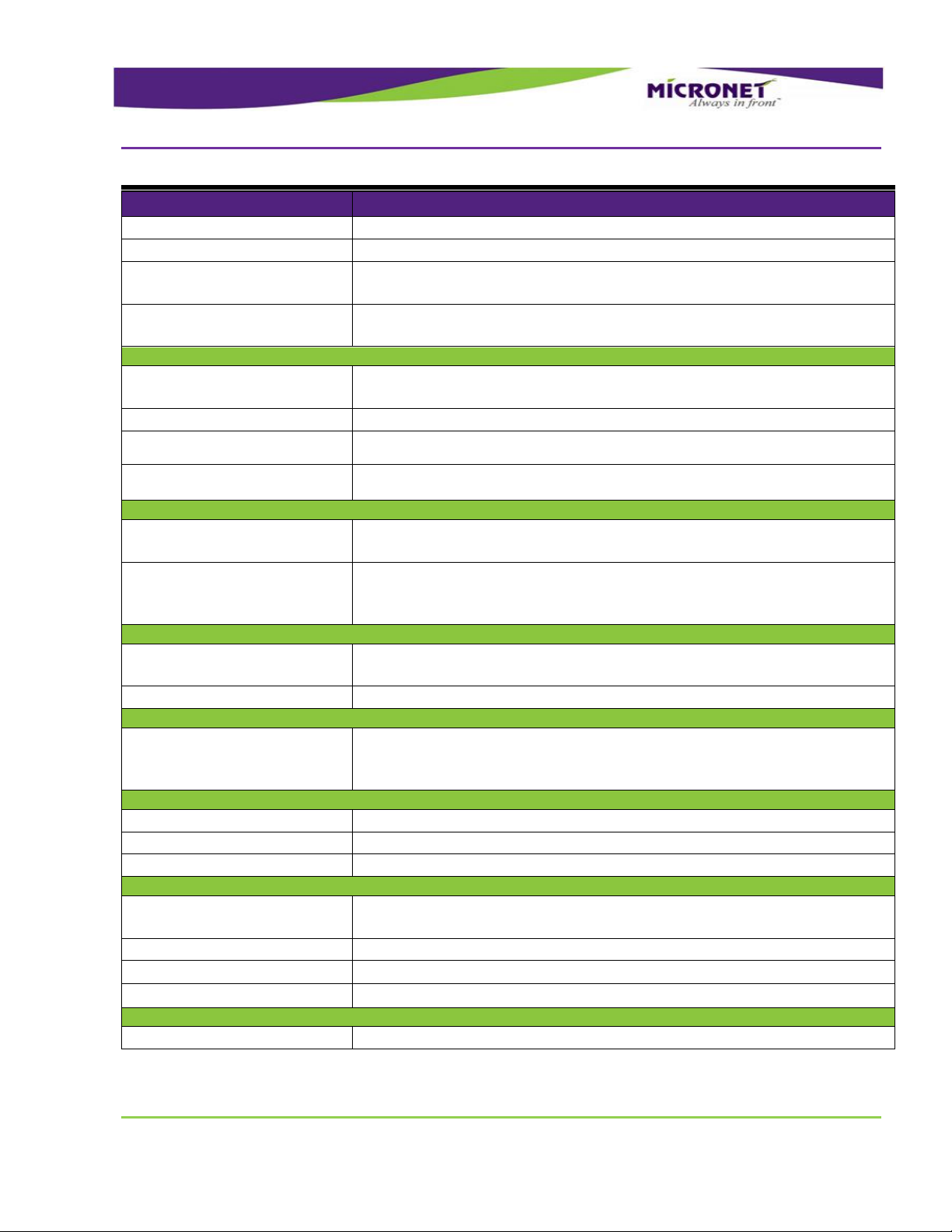
Features
Details
Peripheral Cables
Main interface cable
Supporting all the platform interfaces
Mechanical Accessories
Mounting Arm
RAM® Mount, flexible, multi-directional mounting
SD Card Protective Cover
Optional SD card removal protection
SIM card protective cover
Optional SIM card removal protection
Front Panel Label
Optional Customizable “logo” printout
All-In-One Model Configuration
The All-In-One model configuration includes all the Standard model features plus the following
features:
Platform Accessories
Page 13
Introduction
OEM Optional Features* (requires M-O-Q)
Rev. 1.2
M-317 Hardware Guide
13 / 50
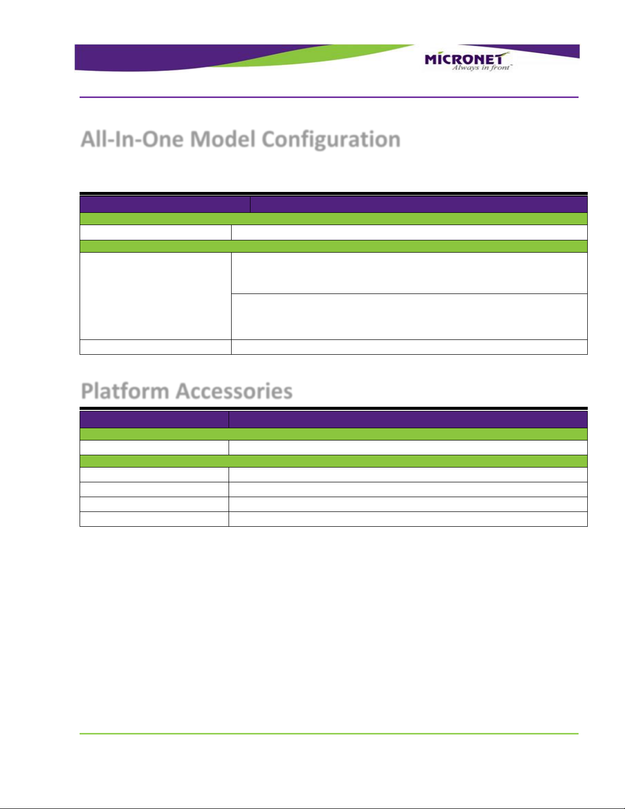
Features
Details
Interface Connections
RS422 Port
(Replacing RS232 Com Port 1)
EIA RS422
External Audio
- Class A or Class D external speaker amplifier (Mono)
- External microphone input (Mono)
Customized Front
Panel Label
Light Sensor
Internal Speaker
Internal Microphone
Keypad
OEM Optional Features* (requires M-O-Q)
*Please inquire about Minimum-Order-Quantity
M-317 Device Components
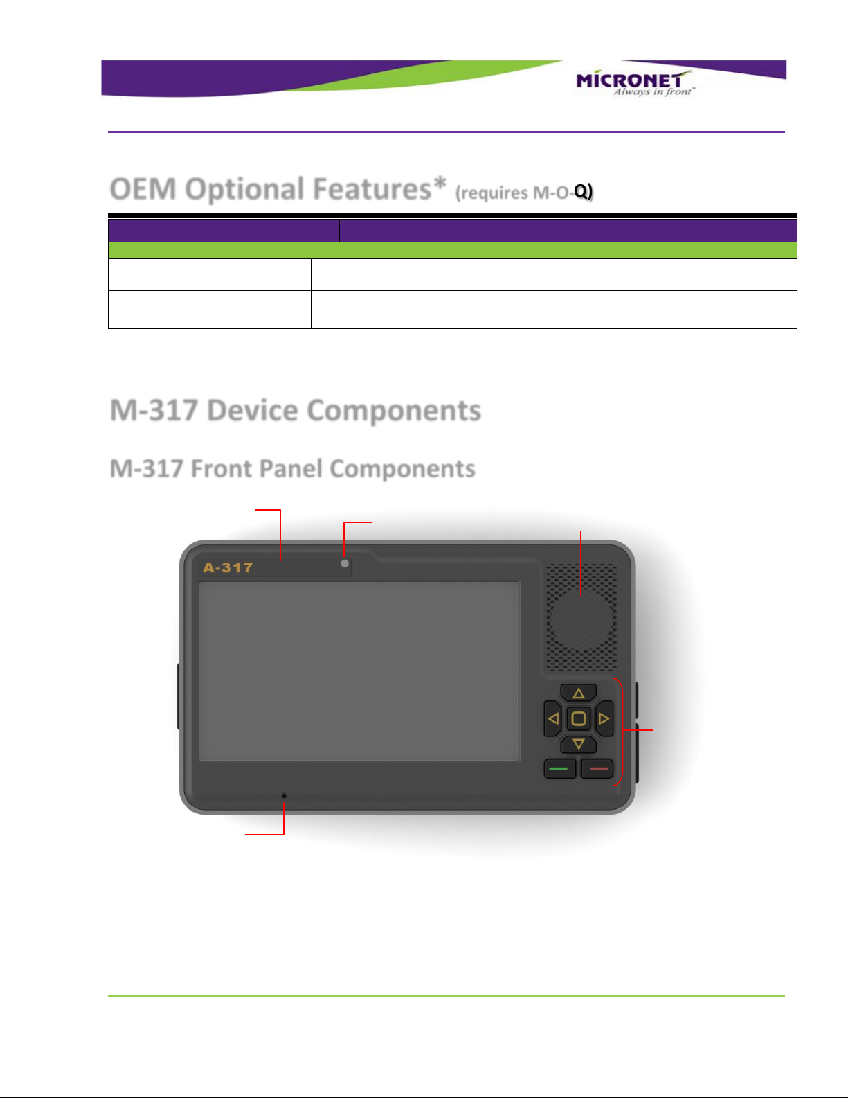
M-317 Front Panel Components
Figure 1: M-317 Front Panel Components
For more information about the M-317 front panel components, see:
Display, on page 21
Page 14

Introduction
M-317 Device Components
Rev. 1.2
M-317 Hardware Guide
14 / 50
Customized Front Panel Label, on page 23
Internal Speaker, on page 24
Keypad, on page 22
Light Sensor, on page 22
Internal Microphone, on page 25
Page 15
Introduction
M-317 Device Components
Rev. 1.2
M-317 Hardware Guide
15 / 50
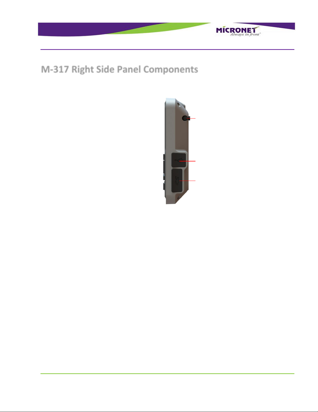
Memory Card Slot
USB Host
Stylus
M-317 Right Side Panel Components
For more information about the M-317 right side panel components, see:
Memory Card Support, on page 20
Device Connector Slot - Rubber Cover, on page 20
USB Host Port, on page 26
Stylus, on page 22
Figure 2: M-317 Right Side Panel Components
Page 16

Introduction
M-317 Device Components
Rev. 1.2
M-317 Hardware Guide
16 / 50
SIM Card Slot
M-317 Left Side Panel Components
For more information about the M-317 left side panel components, see:
Device Connector Slot - Rubber Cover, on page 20
USB Host Port 2, on page 27
Figure 3: M-317 Left Side Panel Components
Page 17

Introduction
M-317 Device Components
Rev. 1.2
M-317 Hardware Guide
17 / 50
Mounting Arm Screw Inserts
Stylus
M-317 Rear Panel Components
For more information about the M-317 rear panel components, see:
Mounting Arm screw inserts, on page 41
Stylus, on page 22
Figure 4: M-317 Rear Panel Components
Page 18

Introduction
M-317 Device Components
Rev. 1.2
M-317 Hardware Guide
18 / 50
Main Device Connector
Cable Mounting Screw Inserts
M-317 Bottom Panel Components
Figure 5: M-317 Bottom Panel Components
For more information about the M-317 bottom panel components, see:
Pinout of Main Device Connector, on page 30
Cable mounting screw inserts
Page 19

Technical and Functional Details
Platform Core
Rev. 1.2
M-317 Hardware Guide
19 / 50
Technical and Functional Details
Platform Core
Operating System
2
The M-317 platform is powered by Google Android 4.0.3 ICS. For information about the M-317’s OS
architecture, please refer to the M-317 Developer's Guide.
Application Development Environment
The M-317 platform supports any open source IDE. Micronet recommends using the Android ADT Eclipse
IDE.
Micronet’s Development Toolkit (DTK) includes the following components:
Full Micronet SDK
Application samples
Device management and upload tools
Development accessories
Documentation
For more details about the development infrastructure, product tools, and DTK contents, please refer to
the M-317 Getting Started Guide.
Processor
TI OMAP3715 1GHz
High-performance Superscalar ARM Cortex™- A8
Page 20

Technical and Functional Details
Platform Core
Rev. 1.2
M-317 Hardware Guide
20 / 50
NOTE:
To prevent uncontrolled power cut-off situations that can cause significant Flash File
System damage, verify that you have a proper power connection to the device. For more
details, see Power Management, page 37.
RAM
The M-317 device provides a total of 512MB of RAM memory (DDR type). Approximately 200MB of the
RAM memory is dedicated for Android system use. The remaining memory is used for RAM storage or
application use (user configurable).
Flash Memory
The M-317 device provides a total of 512MB of Flash memory (NAND type). Approximately 312MB of the
RAM memory is dedicated for Android system use.
The remaining memory is held for data storage and for a Flash File System partition, accessible for the
applications as a persistent data storage drive.
Memory Card Support
The M-317 device provides an MMC / SD card slot with the following parameters:
HC-MMC / SD cards (SDHC) compliant MMC System Specification V4.2 and SD I/O Cards
Specification V2.0
SD memory cards (up to 32GB) supporting FAT16 / FAT32 active disk
Speed: x133
Clocks: Identification mode – 400 KHz, data mode 20 MHz
The MMC / SD (SDHC) card slot is located on the right side panel. By default, a user can physically
access the slot. The platform supports two access protection options. For more details, see the following
section.
Device Connector Slot - Rubber Covers
The M-317 device has rubber covers to protect the SD card slot and USB Host connectors from water
and dust.
Page 21

Technical and Functional Details
User Interface
Rev. 1.2
M-317 Hardware Guide
21 / 50
NOTE:
This feature is used for automatic solution recovery. However, Flash File System corruption
problems can occur if the feature is executed during a file saving operation.
To prevent user access to the SD card and USB Host connector, a permanent plastic cover option is
available. To replace the rubber cover with the plastic one:
1. Remove the rubber cover by removing the rubber snap in the center of the cover.
2. Push the plastic cover into the same place.
After the plastic cover is inserted, these areas can only be accessed by physically breaking the plastic
cover, using an external mechanical tool.
Real Time Clock (RTC)
The M-317 platform provides a Real Time Clock (RTC) that continuously operates even when the device
is powered off. To maintain the RTC, the device must remain connected to the vehicle’s power supply or
to an internal battery.
In addition, the RTC enables powering on the device based on a predefined alarm.
Watchdog
To monitor mission-critical processes, the platform provides an intelligent watchdog mechanism. This
mechanism provides various capabilities for programming an automatic reset of the terminal. The
watchdog mechanism is configurable to control application stability and restart the device if an
application or the system hangs (freezes).
For more details on proper use of the watchdog mechanism, please refer to the Developers Guide.
User Interface
The platform supports a 7” display.
Display
The M-317 model provides a 7” touch color display with WVGA (800 X 480 pixels) resolution.
The display uses the transflective TFT LCD technology, providing high contrast, and supporting 16M
colors and a multi-level white LED backlight with a typical luminous intensity of 350cd/m2.
Page 22

Technical and Functional Details
User Interface
Rev. 1.2
M-317 Hardware Guide
22 / 50
NOTE:
To prevent touch screen overlay damage, avoid coming into contact with the exposed
polarizer using anything harder than the device stylus. To clean dust off the display surface,
gently wipe it with cotton, chamois, or any other soft material. To decrease the wear of the
touch screen overlay, specify your software application architecture to use device keys to
enable the most commonly used application functions.
Touch Screen and Stylus
Each model’s display provides an analog-resistive-technology-based touch screen overlay that supports
a minimum of one million touches (via the stylus or finger).
Stylus
A plastic stylus is stored in the rear panel of the device for signature capture or other touch screen
operations.
Light Sensor
The platform provides a light sensor component, which is located near the top center of the front panel.
Applications use this sensor to recognize light and dark working modes, as well as to help with device
backlight adjustments.
The system provides a function allowing for automatic keypad and display backlight adjustments based
on the light sensor status. For more details about the light sensor, please refer to the Developers Guide.
Keypad
The M-317 device provides integrated rubber keys for operational convenience and safety. The
Elastomer rubber tactile keypad includes the following:
4 directional keys (Up, Down, Left, and Right)
3 control keys (Accept, Decline, and Push)
Page 23

Technical and Functional Details
User Interface
Rev. 1.2
M-317 Hardware Guide
23 / 50
Figure 6: M-317 Control, Direction and Menu Keys
Decline
Accept
Push
Down
Up
Left
Right
All the keys are backlit and configurable to provide system audio feedback during use.
You can connect an additional external keyboard using the optional USB host port connection, if
required.
Customized Front Panel Label (Optional)
Micronet provides the option to attach a customized front panel label based on your specifications. To
enable rebranding the product, Micronet will provide graphic files and size specifications. This is subject
to an additional charge per unit, based on the quantity ordered. Once printed, Micronet will store the
labels and use them for orders placed for this product.
Page 24

Technical and Functional Details
Audio Support
Rev. 1.2
M-317 Hardware Guide
24 / 50
Figure 7: Customized Front Panel Label
Audio Support
Audio CODEC
The platform provides a multi-channel audio CODEC that supports and manages all basic and optional
platform audio components. Developers can control internal and external speakers and microphone
functions using the software API.
Internal Speaker
The M-317 device provides one 3W / 8Ω integrated speaker located on the front panel. The speaker
connects to the mono channel of the platform’s audio CODEC and provides a nominal volume of 90 dB @
0.1m.
External Speaker Connection (Optional)
The M-317 device optionally provides a mono loudspeaker output of 2.75W / 4 OHM and 2.25W / 8
OHM, connected to the main device connector.
For more information about the interface signals, please see the External Speaker signal map, page 34.
Page 25

Technical and Functional Details
Communication Interfaces
Rev. 1.2
M-317 Hardware Guide
25 / 50
NOTES:
The Windows OS is not specified as a real time OS. Thus, it is highly recommended to
implement flow control functionality using serial communication to guarantee a strong and
stable communication flow for your application.
Internal Microphone
The platform provides an integrated high-sensitivity microphone, located at the bottom left of the front
panel.
External Microphone Connection (Optional)
The M-317 device optionally provides an audio mono input signal for an external microphone
connection.
Microphone requirements/recommendations:
Electret type of microphone
2.2V Feeding source
Resistance up to 2K
For more information about these interface signals please see the External Microphone signal map, page
34.
Communication Interfaces
Serial Communication
The platform supports two serial communication ports for external devices and peripheral connections.
These ports support various hardware and software flow control functions.
Serial Port 1 (COM1)
The platform provides an EIA-RS232 level serial communication port. This port connects to the main
device connector, supporting a baud rate of 300 to 115,200bps, and provides one pair of
communication-control handshake signals (CTS / RTS).
Generally, Serial Port 1 operates as a main system serial port for modem or AVL box communication.
Page 26

Technical and Functional Details
Communication Interfaces
Rev. 1.2
M-317 Hardware Guide
26 / 50
For more information about the interface signals, please see the Serial Port 1 signal map on page 33.
RS422 Port (COM1) (Optional)
Serial Port 1 can be optionally configured (factory setting) to provide EIA-RS422 level serial
communication. This option replaces the RS232 signals using the same connector pins.
For more information about the interface signals, please see the RS-422 Port signal map on page 33.
Serial Port 2 (COM2)
Serial Port 2 is a second RS232 port. This port connects to the main device connector, supporting a
baud rate of 300 to 115,200bps, and only provides the TX and RX signals.
For more information about the interface signals, please see the Serial Port 2 signal map on page 34.
USB Communication
The platform optionally supports up to three USB (Universal Serial Bus) communication ports for
external devices / peripheral connections (two USB Hosts and one USB Client device).
The USB Host interface supports the following profiles:
USB Standard HID
USB Printer (PCL)
USB Storage
The USB Client interface supports Android ADB for application development and device management
using the USB Client Extension Cable described below.
USB Host Port
The USB Host communication port is connected to the USB connector located on the right panel of the
device.
The USB Host port supports the USB 2.0 low, full, and high-speed communications standards.
USB Host Port 1
The USB Host Port 1 connects to the main device connector. This port supports the USB2.0 low, full, and
high-speed communications standards.
Page 27

Technical and Functional Details
Peripheral Controls
Rev. 1.2
M-317 Hardware Guide
27 / 50
NOTE:
The USB Host port provides up to 500 mA of power consumption for non-self-powered
client devices.
NOTE:
The USB Host port provides up to 500 mA of power consumption for non-self-powered
client devices.
For more information about these interface signals please see the USB Host 1 signal map on page 33.
USB Host Port 2 (Optional)
The USB Host Port 2 is located on the right panel of the device. This port supports the USB2.0 low, full,
and high-speed communications standards.
For more information about these interface signals please see the USB Host 2 signal map on page 33.
USB Client
The USB Client port provides by using a USB Client Extension Cable (Includes in the M-317 DTK). This
cable is used for Android’s ADB protocol and supports:
Device configuration
Management tools
Application development
Debugging
Peripheral Controls
Digital Inputs
The platform provides two digital inputs, IN1 and IN2 (automotive voltage level), for monitoring the
ignition switch signal and other signals.
The input signals connect to the main device connector.
Page 28

Technical and Functional Details
Wireless Communication
Rev. 1.2
M-317 Hardware Guide
28 / 50
NOTE:
IN1 is also used to power on the device from the shutdown state. For proper power
management implementation, the input must be connected to the vehicle's ignition
switch. The platform provides various software control options for this essential feature.
For more details, please refer to the Digital I/O and Power Management sections of the
Developers Guide.
Input State
Typical
Minimum
Maximum
Low
0V
-30V
+5V
High
12V-24V
+8V
+30V
Parameter
Value
Maximum switchable voltage
+VIN
Maximum switchable current
300mA
Table 1: Input State Electrical Parameters
For more information about this interface signal, please see the Digital Input signal map on page 33.
Digital Outputs
The platform provides a digital output (Open Collector) for external peripheral control. This signal
connects to the main device connector.
Table 2: Open Collector Output Electrical Parameters
For more information about these interface signals please see the Digital Output signal map on page 33.
Analog Input
The platform provides an analog input signal to monitor the voltage range of compatible vehicle sensors,
such as an analog fuel gauge. This signal connects to the main device connector.
The supported voltage range is from 0V to 30V.
For more information about these interface signals please see the Analog Input signal map on page 33.
Page 29

Technical and Functional Details
Wireless Communication
Rev. 1.2
M-317 Hardware Guide
29 / 50
Wireless Communication
Wireless LAN and Bluetooth Class2
Overview
The M-317 platform provides an optional combined Wireless Local Area Network (IEEE 802.11) and
Bluetooth (Class2) communications module.
Wireless LAN communication is especially suited for high-speed data transfer over the air, when a
Wireless LAN hotspot infrastructure exists. For applications that require large data transactions, Wireless
LAN is the most economical way to implement the solution.
Bluetooth communication is used for Bluetooth-enabled connections with peripherals such as an audio
headset and printer.
The M-317 Wireless LAN and Bluetooth Class2 module adopts TI’s latest highly integrated WLAN and
Bluetooth SoC, LSR’s TiWi-R2, which is based on TI’s WL1271 chipset.
Wireless LAN Operation
The WLAN module is compliant with the IEEE 802.11 b/g/n standard and uses DSSS (Direct Sequence
Spread Spectrum), OFDM (Orthogonal Frequency Division Multiplexing), DBPSK, DQPSK, CCK, and QAM
baseband modulation technologies.
In addition to supporting WPA / WPA2, WEP 64-bit, and 128-bit encryption, this module supports the
following:
IEEE’s 802.11i security standard through the implementation of AES (Advanced Encryption Standard),
CCMP (Counter Mode CBC-MAC Protocol), and WEP with TKIP security mechanisms.
IPsec with DES / 3DES / ASE encryption and MD5 / SHA-1 authentication
WAPI specifications for the Chinese market
(the AW-GH381 supports) 802.11e QoS (Quality of Service) for voice applications
Bluetooth Operation
The Bluetooth module is Bluetooth 2.1 + EDR (Enhanced Data Rate) compliant.
The M-317 system supports the following Bluetooth communication profiles:
Serial interface profile
Page 30

Main Connector Signal Map
Wireless Communication
Rev. 1.2
M-317 Hardware Guide
30 / 50
Pin
Signal
Type
Function
Specifications
1
VIN_GND
G
MDT Power supply
Ground
2
VIN_GND
G
Overview
This chapter describes the basic and optional device interface signals found on the main device
connector.
The connector type is a male D-Sub 44 Pin connector. All pins are ESD protected (against electrostatic
discharge). The connector’s “shield” pins are tied to ground.
3
Main Connector Signal Map
This chapter uses the following abbreviations:
I - Input signal
O - Output signal
B - Bus signal
V - Voltage signal
G – Ground
Pinout of Main Device Connector
Pinout by Pin Number
The following table lists the connector’s signals by pin number.
Table 3: Main Device Connector Signal Map (by Pin Number)
Page 31

Main Connector Signal Map
Wireless Communication
Rev. 1.2
M-317 Hardware Guide
31 / 50
Pin
Signal
Type
Function
Specifications
3
+VIN
V
Input Power
12V/24V
Typical – 12V/24V
- Minimum continues – 6V (5V for up to
40ms according to ISO7637)
- Maximum continues – 32V
4
+VIN
V
5
GND
G
Ground
6
7
8
I/O
CAN Low Signal
9
I/O
CAN High Signal
10
USB Host 1 D-
B
USB Host Port1 Data-
Universal Serial Bus Specification Rev 2
11
USB Host 1 D+
B
USB Host Port1 Data+
Universal Serial Bus Specification Rev 2
12
USB Host 1 +5V
V
USB Host Port1 VBUS
Universal Serial Bus Specification Rev 2
13
USB Host 1 GND
G
Ground
Universal Serial Bus Specification Rev 2
14
USB OTG D+
+
USB OTG Data+
Universal Serial Bus Specification Rev 2
15
USB OTG D-
-
USB OTG Data-
Universal Serial Bus Specification Rev 2
V
Universal Serial Bus Specification Rev 2
G
Ground
Universal Serial Bus Specification Rev 2
18
N/A
20
ANA_IN
I
Analog Input
0V-30V max, 12k OHM
24
ANA_IN GND
G
Ground
27
Dig_Out1
O
Digital Output 1
Open Collector
Max. switchable current = 300mA
Max. switchable voltage = +VIN
Max. saturation voltage = 0.6V
28
Dig_In1
I
Digital Input 1 (Ignition
Typical Min Max
Page 32

Main Connector Signal Map
Wireless Communication
Rev. 1.2
M-317 Hardware Guide
32 / 50
Pin
Signal
Type
Function
Specifications
switch)
Input Low: VIL 0V -30V 6V
Input High: VIH 12V-24V +8V +30V
29
N/A
30
N/A
31
GND
G
Ground
32
TXD1
or
422 RX-
O
RS232 Transmit Data
(COM1)
or
RS422 Receive Data -
EIA-RS232 level
EIA-RS422 level
33
RTS1
or
422 RX+
O
RS232 Request To
Send (COM1) or
RS422 Receive Data +
EIA-RS232 level
EIA-RS422 level
34
RXD1
or
422 TX-
I
RS232 Receive Data
(COM1)
or
RS422 Transmit Data-
EIA-RS232 level
EIA-RS422 level
35
CTS1
or
422TX+
I
RS232 Clear To Send
(COM1)
or
RS422 Transmit Data+
EIA-RS232 level
EIA-RS422 level
36
RS-232 GND
G
Ground
I
(COM2)
O
(COM2)
EIA-RS232 level
39
RS-232 GND
G
Ground
40
EXT_SPEAKER-
G
External Speaker -
(optional)
41
EXT_SPEAKER+
G
External Speaker +
(optional)
42
GND G Ground
43
EXT_MIC+
G
External Microphone +
(optional)
44
EXT_MIC-
G
External Microphone -
(optional)
Pin
Signal
Type
Function
Specifications
Pinout by Functionality
The following table lists the connector’s signals by functionality.
Table 4: Main Device Connector Signal Map (by Functionality)
Page 33

Main Connector Signal Map
Wireless Communication
Rev. 1.2
M-317 Hardware Guide
33 / 50
Pin
Signal
Type
Function
Specifications
1
VIN_GND
G
MDT Power supply
Ground
2
VIN_GND
G
3
+VIN
V
Input Power
12V/24V
Typical – 12V/24V
- Minimum continues – 8V
- Maximum continues – 32V
4
+VIN
V
6
7
8
I/O
CAN Low Signal
9
I/O
CAN High Signal
10
USB Host 1 D-
B
USB Host Port1 Data-
Universal Serial Bus Specification Rev 2
11
USB Host 1 D+
B
USB Host Port1 Data+
Universal Serial Bus Specification Rev 2
12
USB Host 1 +5V
V
USB Host Port1 VBUS
Universal Serial Bus Specification Rev 2
13
USB Host 1 GND
G
Ground
Universal Serial Bus Specification Rev 2
20
ANA_IN
I
Analog Input
0V-30V max, 12k OHM
24
ANA_IN GND
G
Ground
27
Dig_Out1
O
Digital Output 1
Open Collector
Max. switchable current = 300mA
Max. switchable voltage = +VIN
Max. saturation voltage = 0.6V
28
Dig_In1
I
Digital Input 1 (Ignition
switch)
Typical Min Max
Input Low: VIL 0V -30V
6V
Input High: VIH 12V-24V +8V
+30V
32
TXD1
or
422 RX-
O
RS232 Transmit Data
(COM1)
or
RS422 Receive Data -
EIA-RS232 level
EIA-RS422 level
33
RTS1
or
422 RX+
O
RS232 Request To Send
(COM1) or
RS422 Receive Data +
EIA-RS232 level
EIA-RS422 level
34
RXD1
or
422 TX-
I
RS232 Receive Data
(COM1)
or
RS422 Transmit Data-
EIA-RS232 level
EIA-RS422 level
35
CTS1
or
I
RS232 Clear To Send
(COM1)
EIA-RS232 level
EIA-RS422 level
Page 34

Main Connector Signal Map
Wireless Communication
Rev. 1.2
M-317 Hardware Guide
34 / 50
Pin
Signal
Type
Function
Specifications
422TX+
or
RS422 Transmit Data+
36
RS-232 GND
G
Ground
37
RXD2
I
RS232 Receive Data
(COM2)
EIA-RS232 level
38
TXD2
O
RS232 Transmit Data
(COM2)
EIA-RS232 level
39
RS-232 GND
G
Ground
40
EXT_SPEAKER-
G
External Speaker -
(optional)
41
EXT_SPEAKER+
G
External Speaker +
(optional)
42
GND G Ground
43
EXT_MIC+
G
External Microphone +
(optional)
44
EXT_MIC-
G
External Microphone -
(optional)
5
GND G Ground
31
GND G Ground
14-19
N/A
21-23
N/A 25-26
N/A 29-30
N/A
Page 35

Platform Power
Overview
Rev. 1.2
M-317 Hardware Guide
35 / 50
WARNING!
The M-317 has no internal fuse, and should therefore be connected directly to the vehicle's
battery power source via a 10A fuse. An inline fuse holder with a 3A fuse (HHC/HHD blade-type
fuses), should be added to the M-317 power cable. See Vehicle Battery Connection, on page 45.
WARNING!
Do not connect the terminal power to the ignition switch signal. This can cause uncontrolled
power cut offs, which may have a detrimental effect on the operating system. Instead, connect
the terminal power directly to the car battery and the ignition switch signal to the device’s
Automotive Input. When the ignition switch signal is powered off, use the shutdown function to
power off the terminal, ensuring that all files and sessions have first been closed.
Overview
The M-317 power comes directly from the vehicle's 12V/24V DC battery and provides intelligent
power management options that reduce drain on the vehicle’s battery. In addition, the M-317 also
enables the control of external peripheral power, backlight and power lines for internal modules.
4
Platform Power
Both internal and external devices can be turned on and off, as required.
Battery Voltage Input
The M-317’s power is connected through the main device 44 pin connector [pin 3 and 4 (+) and pin
1 and 2 (-)], directly to the vehicle’s battery or VLU (Vehicle Location Unit), to provide constant
power. The M-317’s nominal voltage supply, from the vehicle’s battery is 12v or 24v, and the
operating range is between 8v and 30v.
Page 36

Platform Power
Super Capacitors
Rev. 1.2
M-317 Hardware Guide
36 / 50
M-317 Basic Configuration Current Consumption
Power OFF
Suspend
Idle Mode Load
12V
24V
12V
24V
12V
24V
3mA
3mA
30mA
20mA
280 mA
160mA
Super Capacitors
In order to prevent device storage drive corruption during an unpredictable power cut-off or voltage
cranking situation (during vehicle ignition for instance), the M-317 offers a super capacitor option for
short power backup.
Using this option, the device monitors the input-power voltage level and, if the power voltage drops
below 4.7VDC, the system closes the device’s backlight and disables the write access to the Flash
storage, USB storage and SD card memory. If the voltage level increases to a value above 3.8V DC
within 200 milliseconds, the backlight and storage access will be re-enabled and the device will
continue to perform as usual. If the voltage remains low for more than 200 milliseconds, the device
will perform a shutdown.
Device Power Consumption
Table 5: M-317 Basic Configuration Current Consumption
Page 37

Power Management
Overview
Rev. 1.2
M-317 Hardware Guide
37 / 50
Overview
The M-317 system provides smart power management during device operation. The power management
capabilities include power state management, performance adjustment, automatic backlight and
additional power consumption control.
5
Power Management
The power management capabilities are especially helpful when the device is connected to the vehicle’s
battery and the ignition switch is off. Most of this functionality is transparent to application developers.
However, the rest is configurable and the developer can adjust it for specific use. For more information
on the M-317 platform power-management architecture, please refer to the “Power Management”
section in the Developers Guide.
Understanding Power States
The following explanation provides the characteristics of the power states and events that trigger the
device to enter to, and exit from each state.
Backlight Dimming
The backlight dimming timeout and brightness can be configured through the Settings display screen.
Shutdown
Performing a long press on the Decline key will power off the device.
State characteristics:
Main storage is flushed; settings are preserved
Page 38

Power Management
Overview
Rev. 1.2
M-317 Hardware Guide
38 / 50
RTC is alive
Memory allocation is not preserved
GPS Almanac is preserved
Triggers to Enter the State:
Pressing and holding the Decline key for 3 seconds
Calling the API function
Expiring system Power management timeouts
Triggers to Exit the State:
Pressing the Push key
RTC alarm occurrence
Receiving a signal from Automotive Digital Input 1
Warm BOOT Reset
State characteristics:
Main storage (files and registry) is flushed; settings are preserved
RTC is alive
Memory allocation is not preserved
Object Store is preserved
GPS Almanac is preserved
Triggers to Enter the State:
Figure 8: Device Manual Software Shutdown
Page 39

Power Management
Overview
Rev. 1.2
M-317 Hardware Guide
39 / 50
WARNING!
It is highly recommended that the driver not use the Warm BOOT reset. Only a technician
or developer should perform this operation for troubleshooting purposes. Do not perform
this operation while the application is saving data to the Flash storage as it may damage
the Flash File system.
Pressing and holding the DECLINE, UP and DOWN keys for 1 second
Calling the API function
Figure 9: Device Manual Warm BOOT Reset
Hardware Power Down
This is a shelf storage power down state.
State characteristics:
Main storage (files and registry) is flushed; settings are preserved
RTC is not alive (system time is reset)
Memory allocation is not preserved
Triggers to Enter the State:
Pressing DECLINE, Up and DOWN keys for 5 seconds
Triggers to Exit the State:
Pressing the Push key
Page 40

Power Management
Overview
Rev. 1.2
M-317 Hardware Guide
40 / 50
NOTE:
This hardware power down state is for storage purposes only. The RTC is not saved and
the memory allocation will reset to its factory settings.
Figure 10: Device Manual Power Down
Page 41

Device Installation
Mechanical Installation
Rev. 1.2
M-317 Hardware Guide
41 / 50
NOTE:
This guide describes the terminal installation options that use the mounting arm only.
In-vehicle installation instructions must be provided by a qualified installation technician.
Mechanical Installation
Mounting Arm
6
Device Installation
The rear panel of the M-317 provides the mechanical infrastructure for a RAM® mounting-stand
installation.
The RAM® mounting arm is a flexible, rotating, arm-based mount that provides a wide range of fixed in-
cabin positions for maximum comfort and visibility. The mounting-arm screw-insert positions on the M317 rear panel are compatible with the RAM® Mount's standard mounting-arm products.
Mounting Inserts Location and Dimensions
There are four M5 thread mounting PEM Screw Inserts found on the back panel of the M-317.
Micronet provides four screws with the RAM® mounting arm. If you choose another type of mounting
arm, you must take in account the Mounting Arm Ball Stud base depth when calculating the screw
thread length.
Page 42

Device Installation
Mechanical Installation
Rev. 1.2
M-317 Hardware Guide
42 / 50
Figure 11: M-317 Back Panel Mounting Arm Screw Inserts
Mounting Arm Screw Inserts Dimensions
Figure 12: M-317 Back Panel Mounting Arm Screw Insert Dimensions
Page 43

Device Installation
Mechanical Installation
Rev. 1.2
M-317 Hardware Guide
43 / 50
PEM Screw Inserts
The following parameters present the PEM screw insert dimensions:
1. M5 thread
2. PEM thread length 6.6 mm
3. Screw length 5-5.5 mm + Mounting Arm Ball Stud depth
Figure 13: M-317 Back Panel Mounting Arm PEM Screws Inserts Dimensions
Mounting Arm Ball Stud
Figure 14: Mounting Arm Ball Stud
Page 44

Device Installation
Mechanical Installation
Rev. 1.2
M-317 Hardware Guide
44 / 50
Device Installation Steps
1. Determine the optimal positioning of the M-317 device in the vehicle that provides easy access and
a clear view of both the road and the display.
2. Attach the base of the mounting-arm assembly to the dashboard or cabin.
3. Attach the mounting arm to the rear panel of the device, using the mounting screw inserts.
4. Connect the M-317 device with the mounting arm to the mounting arm base.
5. Adjust for the optimal device position and fix it by tightening the mounting-arm wing nut.
6. Follow the power cable preparation as described in Electrical Installation, on page 45.
Page 45

Device Installation
Electrical Installation
Rev. 1.2
M-317 Hardware Guide
45 / 50
NOTE:
The M-317 device has no internal fuse and therefore, should be connected to the
vehicle's power line protected by a 10A fuse. An inline 3A "Slow Blow" fuse (with a
fuse holder for HHC/HHD blade-type fuses) should be added to the power cable.
WARNING!
Do not connect the terminal power to the ignition switch signal. This will prevent
uncontrolled power cut-offs, which may have a detrimental effect on the operating
system.
The +Vin signals of the device must be directly connected to the Vehicle battery. To
properly set up the power management, you must connect the vehicle’s Ignition
Switch signal to the digital input (In1) of the device. For more information about the
power management architecture of the platform, see Power Management on page
37.
Electrical Installation
The main device connector, a D-SUB 44 pin male connector, provides most of the interface signals of
the device. A matching female connector is used to implement the power and peripherals connectivity of
the solution. Please refer to the M-317 Hardware Guide, Main Connector Signal Map, on page 30, for the
main device connector’s signals map.
For cabling customization, please contact your marketing representative.
Figure 15: M-317 Main Device Connector
Vehicle Battery Connection
The M-317’s input power should be connected directly to the vehicle’s battery. See the Electrical
Installation Figure 16 below.
The supported nominal battery voltage supply is 12V or 24V DC, with an operating range between 8V to
30V DC.
Page 46

Device Installation
Electrical Installation
Rev. 1.2
M-317 Hardware Guide
46 / 50
NOTE:
Connecting power to the M-317 does not enable the device. Only pressing the Push
key or having a signal rise on Digital Input 1, enables the device from the powerdown state.
If your solution requires device enabling to the power connection, connect (shorten)
the digital Input1 pin with the power-in signal.
Figure 16: Electrical Installation Scheme
Page 47

Device Installation
Electrical Installation
Rev. 1.2
M-317 Hardware Guide
47 / 50
Electrical Installation Procedure
1. Prepare the wiring for power and all other required peripherals in the vehicle, for connection to the
Accessory cable.
2. Connect the Accessory cable to the M-317 main device connector.
3. The power signals from the Accessory cable should be connected to the vehicle's power line
protected by a 10A fuse. An inline 3A "Slow Blow" fuse (with fuse holder for HHC/HHD blade-type
fuses) should be added to the power cable.
4. To power on the M-317 device press the Push button and verify that all connected peripherals
operate properly.
5. Fix the Accessory cable with cable mounting screws after verifying that all the functions are
performing properly.
6. Arrange the cables using a plastic strip.
Page 48

M-317 Platform Physical Characteristics
Physical Characteristics
Rev. 1.2
M-317 Hardware Guide
48 / 50
Dimension
Measurement
M-317 Dimensions & Weight
Width
Height
Depth
Weight
17.50 oz.
498 Gram
M-317 Platform Physical
Physical Characteristics
7
Characteristics
Table 6: Physical Characteristics
Page 49

Appendix
Appendix A
Rev. 1.2
M-317 Hardware Guide
49 / 50
Appendix A
Regulations & Certifications
8
Appendix
The M-317 complies with the following requirements:
FCC Rules (Class B)
CFR 47, Part 15 Subpart B
This equipment has been tested and found to comply with the limits for a Class B digital device,
pursuant to Part 15 of the FCC rules. These limits are designed to provide reasonable protection against
harmful interference when the equipment is operated in a commercial environment.
This equipment generates, uses and can radiate radio frequency energy and, if not installed and used in
accordance with the instructions, may cause harmful interference to radio communications.
However, there is no guarantee that interference will not occur in a particular installation. If this
equipment does cause harmful interference to radio or television reception, which can be determined by
turning the equipment off and on, the user is encouraged to try to correct the interference by one or
more of the following measures:
a) Reorient or relocate the receiving antenna.
b) Increase the separation between the equipment and receiver.
c) Connect the equipment to an outlet on a circuit different from that to which the receiver is
connected.
Page 50

Appendix
Appendix A
Rev. 1.2
M-317 Hardware Guide
50 / 50
FCC Warning
Modifications not expressly approved by the manufacturer could void the
user’s authority to operate the equipment under FCC Rules.
THE MANUFACTURER IS NOT RESPONSIBLE FOR ANY RADIO OR TV
INTERFERENCE CAUSED BY UNAUTHORIZED MODIFICATIONS TO THIS
EQUIPMENT. SUCH MODIFICATIONS COULD VOID THE USER’S AUTHORITY
TO OPERATE THE EQUIPMENT.
d) Consult the dealer or an experienced radio/TV technician.
Instructions concerning human exposure to radio frequency electromagnetic fields
To comply with FCC Section 1.307 (b)(1) discussing human exposure to radio frequency electromagnetic
fields, please perform the following:
Maintain a distance of at least 20cm between the equipment and all persons during the operation of the
equipment.
IC Canada complience
This device complies with FCC Rules Part 15 and with Industry Canada license-exempt RSS standard(s).
Operation is subject to two conditions: (1) This device may not cause harmful interference, and (2) this
device must accept any interference that may be received or that may cause undesired operation.
Le present appareil est conforme aux CNR d'Industrie Canada applicables aux appareils radio exempts
de licence. L'exploitation est autorisee aux deux conditions suivantes :(1) l'appareil ne doit pas produire
de brouillage, et (2) l'utilisateur de l'appareil doit accepter tout brouillage radioelectrique subi, meme si
le brouillage est susceptible d'en compromettre le fonctionnement.
 Loading...