

Page 1
C
C
E
E--
5
5
0
0
0
0
M
Moobbiillee
D
Daattaa TTeerr
m
miinnaall
H
Haarrdd
w
waarree
G
Guuiiddee
Revision C
January 2011
Page 2

Important Notice
Micronet Ltd. All rights reserved.
Micronet Ltd. reserves the right to alter the equipment specifications and descriptions in this publication
without prior notice. No part of this publication shall be deemed to be part of any contract or warranty
unless specifically incorporated by reference into such contract or warranty.
The information contained herein is merely descriptive in nature, and does not constitute a binding offer
for the sale of the product described herein.
All usage of the Micronet Ltd. logotype or trademarks is forbidden without prior written approval from
Micronet Ltd.
Information in this manual is subjected to change without notice.
Micronet shall have neither liability nor responsibility to any person or entity with respect to any loss or
damages arising from the information contained in this book.
Other company and brand products and service names are trademarks or registered trademarks of their
respective holders, for example: ARM Cortex™, Microsoft™, and Microsoft™ products (Windows
Embedded CE™, Compact Framework™, Microsoft Active Sync™, and Visual Studio™).
For further information, contact Micronet, as follows:
Micronet web site: http://www.micronet.co.il
Contact us: http://www.micronet.co.il/Contact_Micronet.html
Additional CE-500 information: http://www.micronet.co.il/Ce500main.html
Page 3

Table of Contents
GDUTUG500/01
CE-500 MDT Hardware Guide
3 / 97
TTaabbllee ooff CCoonntteennttss
Table of Contents........................................................................................................................ 3
Preface ...................................................................................................................... 7
Revision History .......................................................................................................................... 7
Safety Precautions ...................................................................................................................... 8
Usage Precautions .................................................................................................................... 8
Power Supply ........................................................................................................................... 9
Introduction ............................................................................................................ 10
CE-500 Platform Overview .......................................................................................................... 10
CE-504 and CE-507 Models ......................................................................................................... 10
Displays ................................................................................................................................. 11
Physical Interfaces ................................................................................................................... 11
Optional Wireless Modules ........................................................................................................ 11
Fixed Mount and Portable Configuration ...................................................................................... 11
Development Tool Kit ................................................................................................................. 12
Hardware ............................................................................................................................... 12
Software ................................................................................................................................ 12
Documentation ........................................................................................................................ 12
CE-500 Platform Key Feature Specifications .................................................................................. 13
CE-500 Platform Optional Modules ............................................................................................... 15
CE-500 Platform Accessories ....................................................................................................... 16
CE-50X Device Components ........................................................................................................ 17
CE-504 Front Panel components ................................................................................................ 17
CE-507 Front Panel Components ............................................................................................... 18
CE-50X Model, Bottom Panel components ................................................................................... 19
CE-50X Model, Right Side Panel ................................................................................................. 20
CE-50X Model, Left Side Panel Component .................................................................................. 21
CE-50X Model, Rear Panel Components ...................................................................................... 21
Technical and Functional Details ............................................................................. 23
Platform Core ............................................................................................................................ 23
Operating System .................................................................................................................... 23
Application Development Environment ....................................................................................... 23
Processor ............................................................................................................................... 24
RAM ....................................................................................................................................... 24
Flash Memory ......................................................................................................................... 24
Memory Card Support .............................................................................................................. 24
Page 4

Table of Contents
GDUTUG500/01
CE-500 MDT Hardware Guide
4 / 97
Device Connector Slot - Rubber and Plastic Covers ...................................................................... 25
Real Time Clock (RTC).............................................................................................................. 25
Watchdog ............................................................................................................................... 25
User Interface ........................................................................................................................... 26
Display ................................................................................................................................... 26
Touch Screen and Stylus .......................................................................................................... 26
Light Sensor ........................................................................................................................... 27
Keypad................................................................................................................................... 27
Customized Front Panel Label (Option) ....................................................................................... 30
Audio Support ........................................................................................................................... 30
Internal Speakers .................................................................................................................... 30
Internal Microphone ................................................................................................................. 31
Audio CODEC (Option) ............................................................................................................. 31
Communication Interfaces .......................................................................................................... 31
Serial Communication .............................................................................................................. 31
USB (Universal Serial Bus) Communication ................................................................................. 32
Ethernet Communication (Option).............................................................................................. 34
Peripheral Controls ..................................................................................................................... 34
Digital I/O .............................................................................................................................. 34
Analog Input ........................................................................................................................... 36
1-Wire Interface ...................................................................................................................... 36
Terminal Connector Signal Maps .............................................................................. 37
Overview ................................................................................................................................ 37
Pinout of Connectors ................................................................................................................ 38
Platform Power ........................................................................................................ 42
Overview ................................................................................................................................ 42
Vehicle Battery Connection ....................................................................................................... 43
Internal Battery (Option) .......................................................................................................... 44
Device Power Consumption ....................................................................................................... 45
Power Management ................................................................................................. 46
Overview .................................................................................................................................. 46
Understanding Power States........................................................................................................ 46
Suspend ................................................................................................................................. 46
Shutdown ............................................................................................................................... 47
Warm BOOT reset .................................................................................................................... 48
Hardware Power Down ............................................................................................................. 49
Setting Registry to Factory Defaults ............................................................................................. 50
Formatting Flash Memory Storage................................................................................................ 51
Optional Feature Modules ........................................................................................ 52
Overview .................................................................................................................................. 52
Wireless Communication ............................................................................................................. 52
Overview ................................................................................................................................ 52
GSM / GPRS ............................................................................................................................ 52
Page 5

Table of Contents
GDUTUG500/01
CE-500 MDT Hardware Guide
5 / 97
GPS ....................................................................................................................................... 54
Wireless LAN and Bluetooth Class2 ............................................................................................ 55
Peripheral Interfaces .................................................................................................................. 57
CANBus (J1939) ...................................................................................................................... 57
External Audio Module .............................................................................................................. 57
External Video Module .............................................................................................................. 58
Additional Integrated Options ...................................................................................................... 58
Accelerometer ......................................................................................................................... 58
Platform Accessories ............................................................................................... 59
Accessory Cables ....................................................................................................................... 59
Main Interface Cable ................................................................................................................ 61
Enhanced Interface Cable ......................................................................................................... 65
Video and CANBus Interface Cable ............................................................................................. 67
Audio Interface Cable ............................................................................................................... 67
Power Supply adaptors ............................................................................................................... 67
IDC Connector ........................................................................................................................ 67
Molex 43025 Series Connector .................................................................................................. 68
Interface Support ...................................................................................................................... 69
J1708 Convertor Box ................................................................................................................ 69
RS-422 Convertor Box ............................................................................................................. 69
Device Cradle ........................................................................................................... 70
Overview .................................................................................................................................. 70
CE-500 Device Basic Cradle Components ...................................................................................... 71
CE-500 Device Enhanced Cradle Components ................................................................................ 73
Device Cradle Connectors ........................................................................................................... 75
Overvew ................................................................................................................................. 75
Basic cradle connectors ............................................................................................................ 76
Enhanced cradle Connectors ..................................................................................................... 78
Device Installation .................................................................................................. 83
Electrical Installation .................................................................................................................. 83
Overview ................................................................................................................................ 83
Connectors ............................................................................................................................. 83
Electrical Installation Procedure ................................................................................................. 84
Mechanical Installation ............................................................................................................... 84
Overview ................................................................................................................................ 84
Mounting Arm ......................................................................................................................... 85
Fixed-Mounted Device Installation ............................................................................................. 87
Fixed / Portable (Device with Cradle) Installation ......................................................................... 89
Inserting the Device into the Cradle ........................................................................................... 91
Removing the Device from the Cradle ........................................................................................ 92
Optional Feature Modules Installation ..................................................................... 93
CE-500 Platform Physical Characteristics ................................................................ 94
Page 6

Table of Contents
GDUTUG500/01
CE-500 MDT Hardware Guide
6 / 97
Physical Characteristics .............................................................................................................. 94
Appendices .............................................................................................................. 95
Appendix A ............................................................................................................................... 95
Regulations & Certifications ...................................................................................................... 95
Page 7

Preface
Revision History
GDUTUG500/01
CE-500 MDT Hardware Guide
7 / 97
P
Prreeffaaccee
RReevviissiioonn HHiissttoorryy
Revision
Date
Change
A
February, 2010
Document created
B
March, 2010
Adding new power management functionality
B.1
April, 2010
Keypad keys names has been changed (Backspace to Left)
C
January, 2011
Adding CE and FCC certifications.
Page 8
Preface
Safety Precautions
GDUTUG500/01
CE-500 MDT Hardware Guide
8 / 97
SSaaffeettyy PPrreeccaauuttiioonnss
UUssaaggee PPrreeccaauuttiioonnss
WARNING!
Abnormal Conditions
Should the CE-500 become hot or start to emit smoke or a strange odor, immediately turn
off the power and contact your original dealer or an authorized service provider. Continued
usage is dangerous and may result in fire or electric shock.
WARNING!
Foreign Objects
Should any foreign matter get into the CE-500, immediately turn off the power and
contact your original dealer or an authorized service provider.
WARNING!
Damage Caused by Dropping
Should you drop the device and possibly have caused damage, immediately turn off the
power and contact your original dealer or an authorized service provider. Continued usage
is dangerous and may result in fire or electric shock.
WARNING!
Moisture
Keep the device away from vases, planets, cups, glasses, and other liquid containers.
Water or metal getting into the device creates the danger of fire and electric shock.
Continued usage after water or metal has gotten into the CE-500 is dangerous and may
result in fire or electric shock.
CAUTION
Foreign Objects
Ensure that metal or combustible objects are not inserted into any openings. Such objects
may result in fire or electric shock.
CAUTION
Location
Do not place the CE-500 on an unstable or uneven surface. Doing so may cause the CE500 to fall, which may result in personal injury or major damage to the device.
Do not locate the device in extremely humid or dusty areas. Doing so may result in fire or
electric shock.
Read the following safety precautions before installation or operation.
Page 9

Preface
Safety Precautions
GDUTUG500/01
CE-500 MDT Hardware Guide
9 / 97
CAUTION
LCD Screen
Never apply heavy pressure on the CE-500 device display or subject it to strong impact.
Doing so may crack the screen or LCD panel glass, which may result in personal injury or
major damage to the device.
Should the LCD panel glass break, do not touch the liquid inside. Doing so may cause skin
inflammation.
Should liquid from the LCD panel accidentally get into a person's mouth, their mouth must
be immediately washed out with water and a physician consulted.
Should liquid from the LCD panel accidentally get into a person's eyes or onto their skin,
the area must be immediately rinsed for at least 15 minutes with clean tap water and a
physician consulted.
PPoowweerr SSuuppppllyy
WARNING!
Do not use the CE-500 at a voltage other than specified. Doing so may result in fire or
electric shock.
Avoid conditions that can cause damage or breaks in the power cable. Do not place heavy
objects on the power cable and keep it away from sources of heat. Any of the above may
damage the power cable, which may result in fire or electric shock.
Never twist, sharply bend, or pull the power cable. Doing so may result in fire or electric
shock.
Should the power cable become severely damaged (to the point that wires are exposed or
broken), contact your original dealer or service provider about repair or replacement.
Using a damaged electrical cable may result in fire or electric shock.
CAUTION
Keep the power cable away from sources of extreme heat. Heat may melt the covering of
the power cable, which may result in fire or electric shock.
Page 10

Introduction
CE-500 Platform Overview
GDUTUG500/01
CE-500 MDT Hardware Guide
10 / 97
1
1
IInnttrroodduuccttiioonn
CCEE--550000 PPllaattffoorrmm OOvveerrvviieeww
CCEE--550044 aanndd CCEE--550077 MMooddeellss
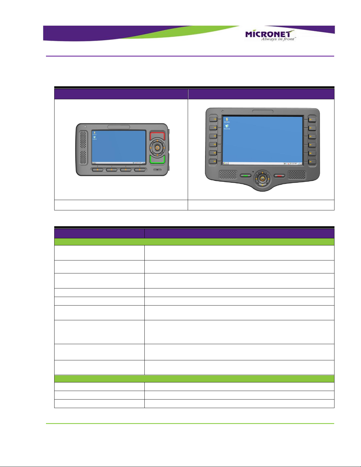
The CE-500 provides Original Equipment Manufacturers (OEMs) and ASPs Application Service Providers
(APS) with a rugged, versatile, vehicle-centric, and fixed-mount or portable mobile-computing platform
for a variety of Mobile Resource Management (MRM) applications.
The platform features Microsoft Windows Embedded CE 6 operating system that supports Compact
Framework 3.5 and offers comprehensive development environment for independent application
programming and system integration.
The CE-500 incorporates a unique layered architecture making the platform highly modular and scalable.
This architecture enables setting various factory-set configurations and performing in-field hardware
upgrades using plug-in modules.
The layered architecture provides a proof and cost-effective design by simplifying maintenance tasks,
significantly extending product life expectancy, and lowing a total cost of ownership (TCO).
The CE-500 Basic configuration is the standard set of features and functions of the MDT. There is a
range of optional Extensions, add-ons and Accessories to further enhance the CE-500 capabilities to
serve advanced fleet management solutions.
The CE-500 is built to withstand a wide temperature range, vibrations, shock, and endure the rough
working conditions in commercial vehicle environment.
Micronet implemented the CE-500 platform in two product models, which are ergonomically designed for
use in commercial vehicles of different sizes. Each model provides a user interface optimized for use in
certain conditions.
Page 11

Introduction
CE-504 and CE-507 Models
GDUTUG500/01
CE-500 MDT Hardware Guide
11 / 97
DDiissppllaayyss
PPhhyyssiiccaall IInntteerrffaacceess
OOppttiioonnaall WWiirreelleessss MMoodduulleess
FFiixxeedd MMoouunntt aanndd PPoorrttaabbllee CCoonnffiigguurraattiioonn
This document describes the full features list of the CE-500 platform. Some of the features are optional
extensions and add-on modules to the Basic configuration. To highlight those extensions, each extension
includes an "option" remark on the feature description.
To support operation in various conditions, you can use different displays with CE-504 and CE-507. The
single core-processing unit supports the following display sizes:
4.3” 480x272 pixels WQVGA (CE-504 model)
7” 800x480 pixels WVGA (CE-507 model)
Each display consists of a color touch screen and large programmable function and control keys.
Both CE-504 and CE-507 provide the following physical interfaces:
USB
Serial RS232 ports
Dedicated interface for Dallas ID button reader
External cameras and audio device connections
Analog and digital control I/O signals
Interfaces for vehicle connectivity
Optionally, a magnetic card reader and camera can be plugged into the models.
Both models provide the ability to plug in optional wireless modules:
Quad band GPRS modem
GPS
Wi-Fi
Bluetooth
All wireless modules are provided with internal antennas.
You can order CE-504 and CE-507 with the following configuration modes:
Page 12

Introduction
Development Tool Kit
GDUTUG500/01
CE-500 MDT Hardware Guide
12 / 97
DDeevveellooppmmeenntt TTooooll KKiitt
HHaarrddwwaarree
SSooffttwwaarree
DDooccuummeennttaattiioonn
Fixed-mount mode, which requires accessory cables for interface connections. The main accessory
cable is required for the power and basic interfaces. Enhanced interfaces require additional cables.
The required accessory cable is specified in the following interface descriptions.
Portable mode, which includes the following components:
Battery for about two hours of full operation. The CE-504 is provided in two configurations, with
or without a main battery.
Device cradle for recharging, mounting and connectivity
Micronet's CE-500 Developers Package provides all tools required for application development quick-
start, product testing, and product evaluation. The Developers Package includes 20 hours of technical
support and contains all essential hardware and software components as described in the following
sections.
Power supply adaptors
Accessory cables
Device cradle
Mounting accessories and tolls
Mechanical and interface connection accessories
Software Development Kit (SDK) provides a set of software tools, API, and documentation for
programming in Visual Studio .NET for C++, C#, and VB development environment.
C# Demo samples of some device features, including the source code
Additional software tools support the CE-500's numerous interfaces
Hardware and software guides
Getting Started guide
Certification approvals and declarations
Page 13
Introduction
CE-500 Platform Key Feature Specifications
GDUTUG500/01
CE-500 MDT Hardware Guide
13 / 97
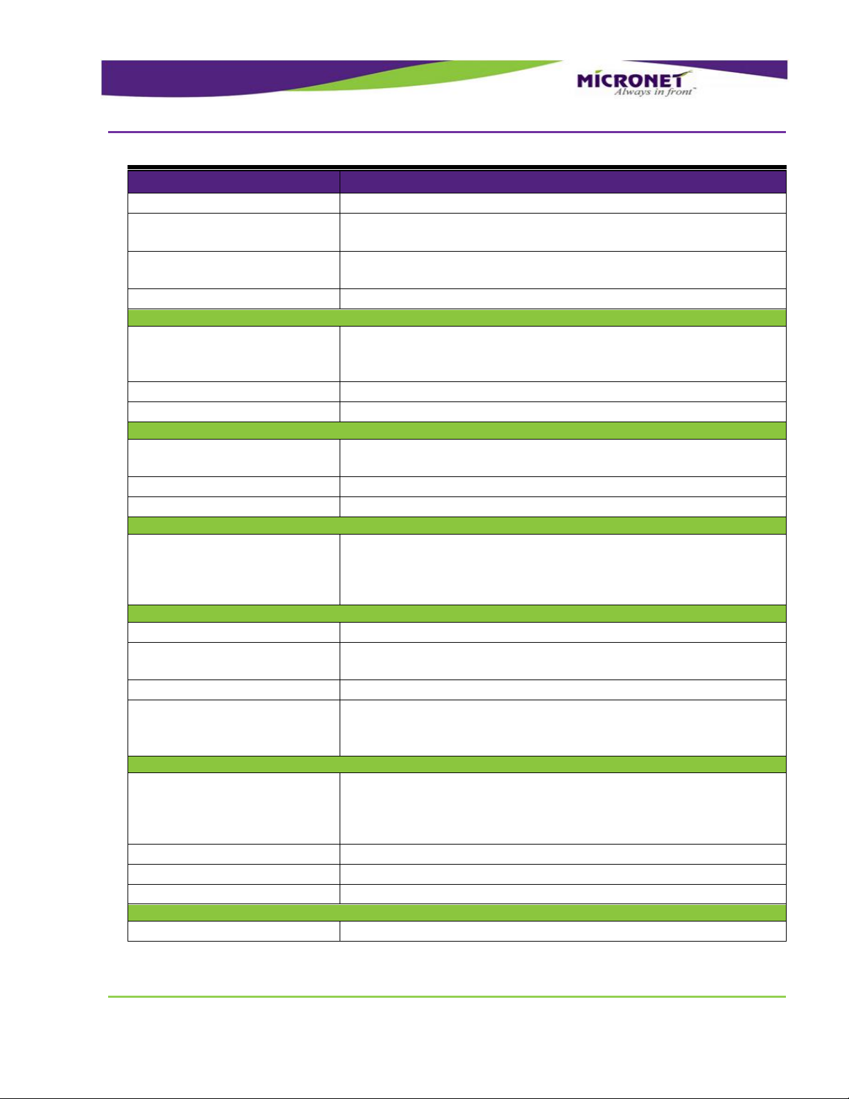
CCEE--550000 PPllaattffoorrmm KKeeyy FFeeaattuurree SSppeecciiffiiccaattiioonnss
CE-504
CE-507
WQVGA (480 X 272)
WVGA (800 X 480)
Basic configuration features
Details
Platform Core
Operating system
- Microsoft Windows Embedded CE 6 Core License
- Professional license available (optional)
Application development
environment
Microsoft Visual Studio 2005 / 2008
Processor
- TI Omap 3503
- ARM Cortex™ - A8 Core
RAM
256MB
Flash
512MB
Memory card support
- SD / MMC (SDHC support) card slot x133 up to 32GB
- SDIO interface
Audio CODEC
- Multi-channel
- System audio support
- Optional GSM Voice and Bluetooth audio support
Real Time Clock
- HW based
- Device Wakeup alarm configuration capability
Watchdog
- SW based for application recovery
- HW based for system recovery
User Interface
Display
Color TFT LCD
Display Backlight
Multi-level backlight (white LED)
Touch screen
Analog Resistive, 4 wire
Table 1 – BASIC configuration
Page 14
Introduction
CE-500 Platform Optional Modules
GDUTUG500/01
CE-500 MDT Hardware Guide
14 / 97
Basic configuration features
Details
Keypad
Rubber tactile, multi-level backlight
Internal speakers
- Stereo, 2 X 1W, 90 dB nominal @ 0.1m
- Multi-level volume control
Internal microphone
- High sensitive
- Noise filtered
Light sensor
Configurable for device backlight adjustment
Communication Interfaces
Rs232 ports
- 1 X 4 Wire (TX, RX, RTS, CTS)
- 1 X 2 Wire (TX, RX)
- 300 - 115200 bps
USB OTG port
USB 2.0 - low, full and high speeds
USB Host port
USB 2.0 - low, full and high speeds
Peripherals Control
Digital I/O
- 2 X automotive inputs
- 1 X open collector output
Analog Input
0V – 30V
1-Wire Interface
Dallas ID memory button support
Power
Input power
- 5V DC power input by device side panel connector
- Direct vehicle battery connection (12V / 24V) by cradle or
accessory cable
- SAE J1455 compliant
Mechanical
Vibration
5 - 1000 Hz, ~4g, 3 axis
Mechanical Shock
- Operational (40g, 11ms, 3 axes)
- Crush safety (75g, 6ms, 3 axes)
Drop
According MIL standard
Device Mounting
- RAM® Mounts compatible mounting arm
- Micronet mounting arm available (optional)
- Device cradle available (optional)
Environmental
Temperature range
- Operating: -4 °F to +158 °F (-20 °C to +70 °C)
- Storage: -22 °F to +176 °F (-30 °C to +80 °C)
- Operating with internal battery option: 14 °F to 140 °F (-10 °C to
+60 °C)
Humidity
0 to 95%, non-condensing
IP
IP54
RoHS
Complaint
Certifications
Standard compliance
FCC, CE, E-Mark
Page 15
Introduction
CE-500 Platform Optional Modules
GDUTUG500/01
CE-500 MDT Hardware Guide
15 / 97
CCEE--550000 PPllaattffoorrmm OOppttiioonnaall MMoodduulleess
Features
Details
Wireless Communication
GSM / GPRS
- Quad Band, GPRS Class10
- GSM voice support
- Including internal on-board antenna
GPS
- High sensitive, 50 channel, -160 dBm
Wireless LAN
- 802.11 b/g
- Including internal on-board antenna
Bluetooth
(combined with Wireless LAN
option above)
- Class 2
- Data and voice support
- Including internal on-board antenna
Interface Connections
Ethernet LAN port
(requires Enhanced accessory
cable or device cradle option)
LAN 10 / 100Mbit/sec
J1939 port
(requires CANBus accessory
Cable or Device Cradle option)
CANBus V2.0B
External Audio
(requires Audio accessory Cable
or Device Cradle option)
- External microphone input (Mono)
- External audio device input (Stereo)
- External audio device output (Mono)
- External speakers output (Stereo)
Portable Model
Internal battery
- 3AH Li-Polymer
- Providing ~2 hours of the operation (device configuration depended)
Device cradle
- Supporting all the platform device models
- Cables connection infrastructure with mechanical cover option
- Device mounting with quick release mechanism
- RAM® Mounts compatible mounting arm
- Micronet mounting arm available (optional)
Page 16
Introduction
CE-500 Platform Accessories
GDUTUG500/01
CE-500 MDT Hardware Guide
16 / 97
CCEE--550000 PPllaattffoorrmm AAcccceessssoorriieess
Features
Details
Power Supply
Wall power adaptor for device
110V / 220V AC to 5V DC
Wall power adaptor for cradle
110V / 220V AC to 12V DC
Peripheral Cables
Main interface cable
Device “Con1” to power, USB, serial, and I/O connectors
Enhanced interface cable
Device “Con2” to serial, I/O, and LAN connectors
J1939 (CANBus) interface
cable
Device “Con3” to CAN connector
Audio interface cable
Device “Con4” to External Audio connectors
Interface Connections
J1708 Adaptor
(requires Enhanced accessory
cable , uses Serial port 2 of CE-
500 device)
RS-232 to J1708 (RS-485) convertor box
RS-422 Adaptor
(requires Enhanced accessory
cable , uses Serial port 2 of CE-
500 device)
RS-232 to RS-422 convertor box
Mechanical Accessories
Mounting arm
- Flexible, multi-directional mounting
- Compatible with cradle or direct device mounting
SD card protective cover
SD card removing protection
SIM card protective cover
SIM card removing protection
Front panel label
Customizable “logo” printout
Page 17
Introduction
CE-50X Device Components
GDUTUG500/01
CE-500 MDT Hardware Guide
17 / 97
CCEE--5500XX DDeevviiccee CCoommppoonneennttss
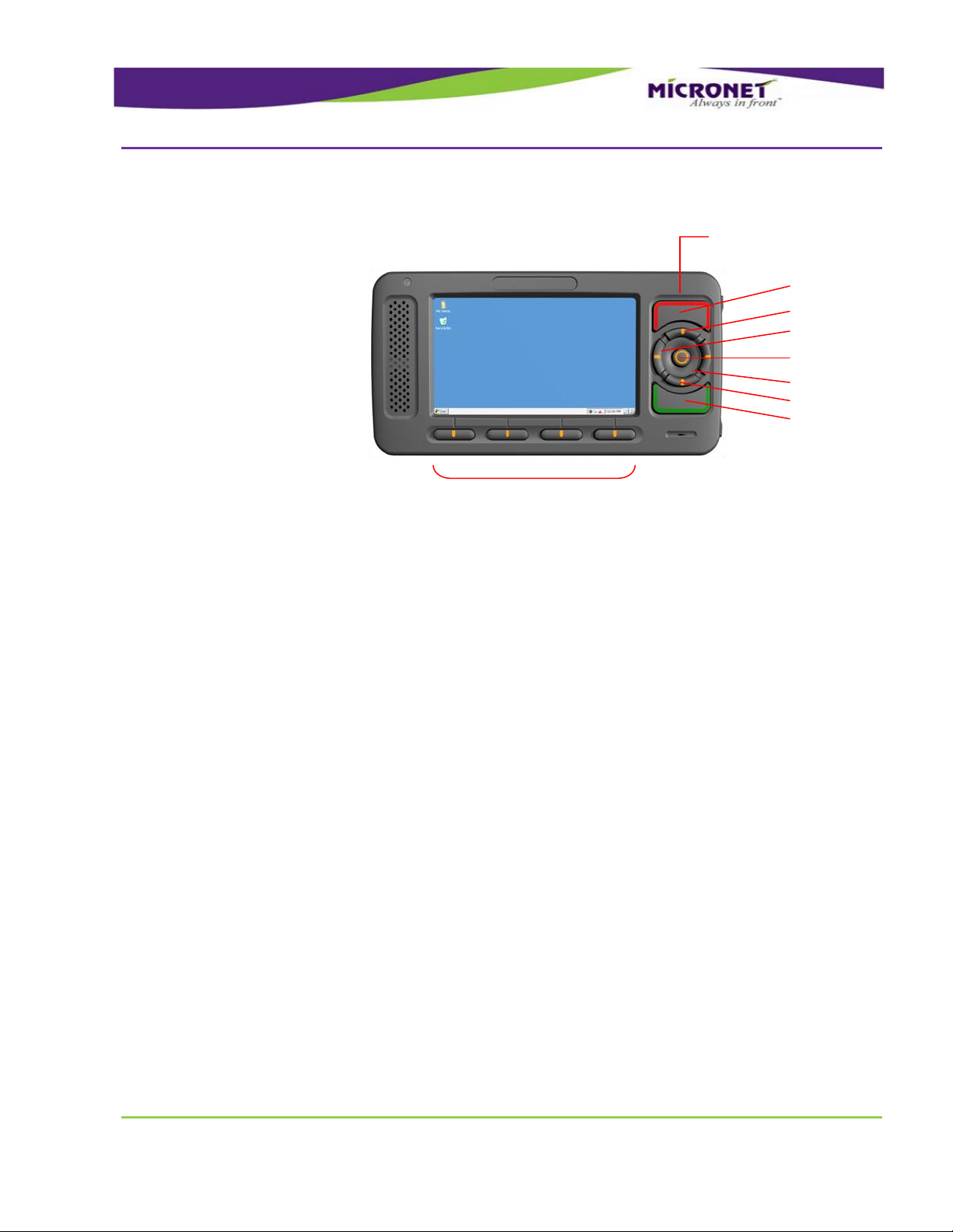
CCEE--550044 FFrroonntt PPaanneell ccoommppoonneennttss
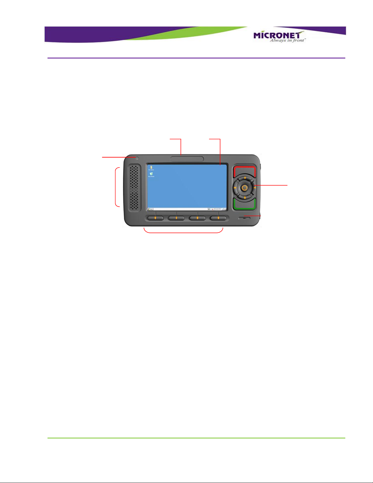
Figure 1 – CE-504 Model, Front Panel components
Internal Speakers
Customized Front Panel Label
Display
Light Sensor
Keypad
Keypad
Internal Microphone
For more information on CE-504 front panel components, see:
Display, on page 26
Customized Front Panel Label, on page 30
Internal Speakers, on page 30
Keypad, on page 27
Light Sensor, on page 27
Internal Microphone, on page 31
Page 18
Introduction
CE-50X Device Components
GDUTUG500/01
CE-500 MDT Hardware Guide
18 / 97
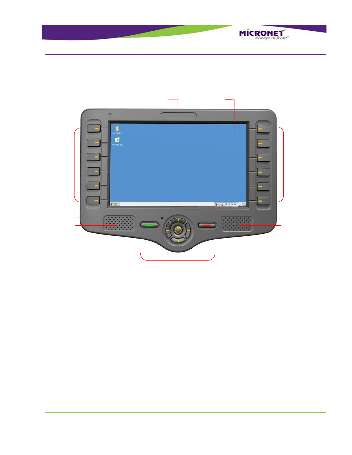
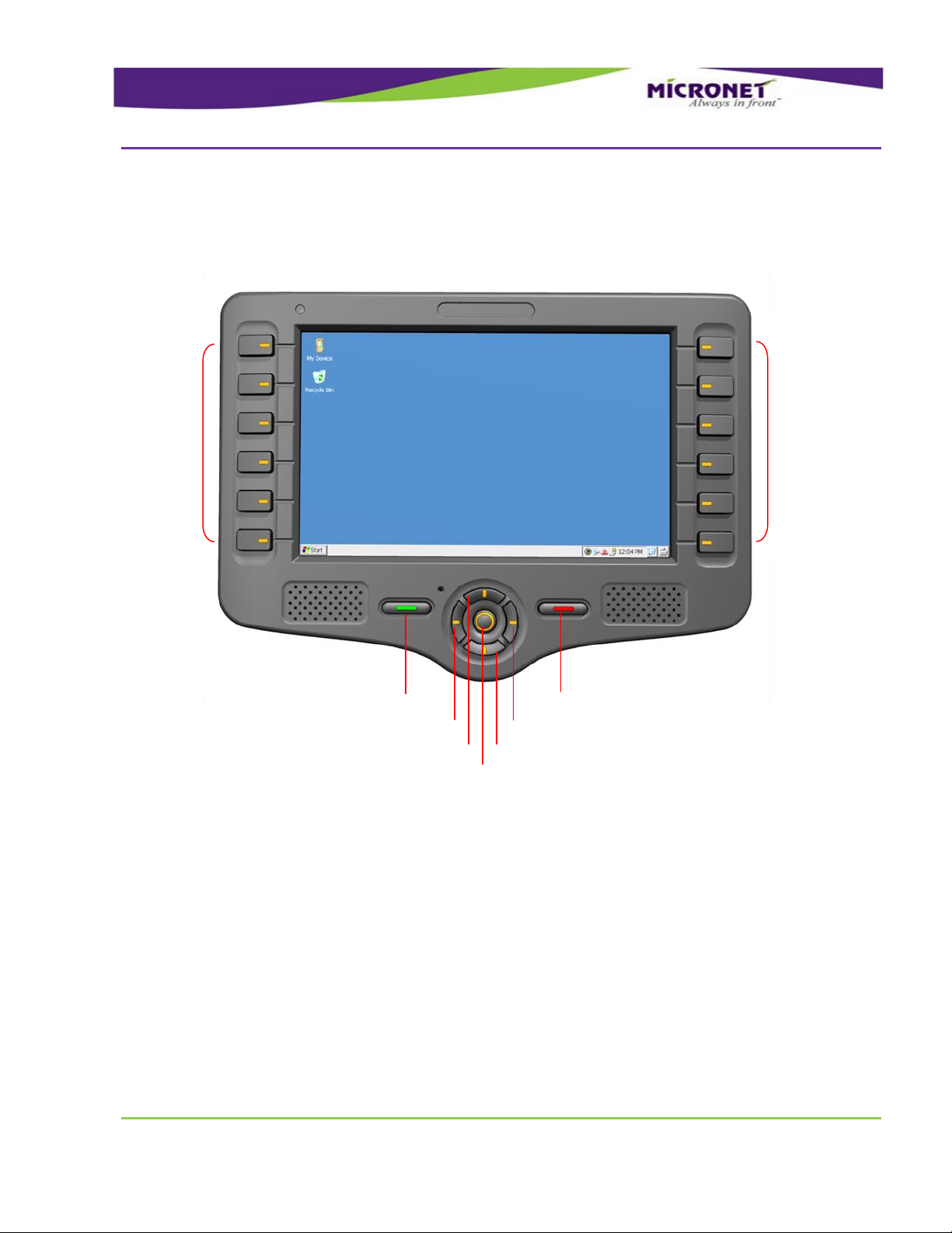
CCEE--550077 FFrroonntt PPaanneell CCoommppoonneennttss
Internal Microphone
Customized Front Panel Label
Display
K
e
y
p
a
d
K
e
y
p
a
d
Keypad
Internal Speakers
Internal Speakers
Light Sensor
For more information on CE-507 front panel components, see:
Display, on page 26
Customized Front Panel Label, on page 30
Internal Speakers, on page 30
Keypad, on page 27
Light Sensor, on page 27
Internal Microphone, on page 31
Figure 2 – CE-507 Model, Front Panel components
Page 19
Introduction
CE-50X Device Components
GDUTUG500/01
CE-500 MDT Hardware Guide
19 / 97
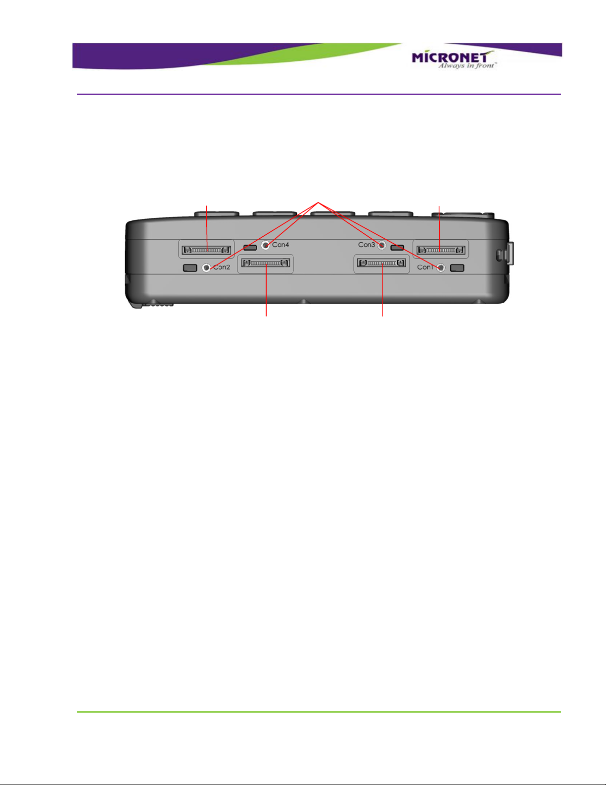
CCEE--5500XX MMooddeell,, BBoottttoomm PPaanneell ccoommppoonneennttss
Figure 3 – CE-50X Model, Bottom Panel components
Optional External Video and
CANBus “Con3” Connector
Optional External Audio
“Con4” Connector
Cable mounting
screw inserts
Main Terminal
“Con1” Connector
Enhanced Terminal
“Con2” Connector
For more information on CE-50X bottom panel components, see:
Main Terminal “Con1” Connector, on page 38
Enhanced Terminal “Con2” Connector, on page 39
Optional External Video and CANBus “Con3” Connector, on page 41
Optional External Audio “Con4” Connector, on page 41
Cable mounting screw inserts, on page 59
Page 20
Introduction
CE-50X Device Components
GDUTUG500/01
CE-500 MDT Hardware Guide
20 / 97
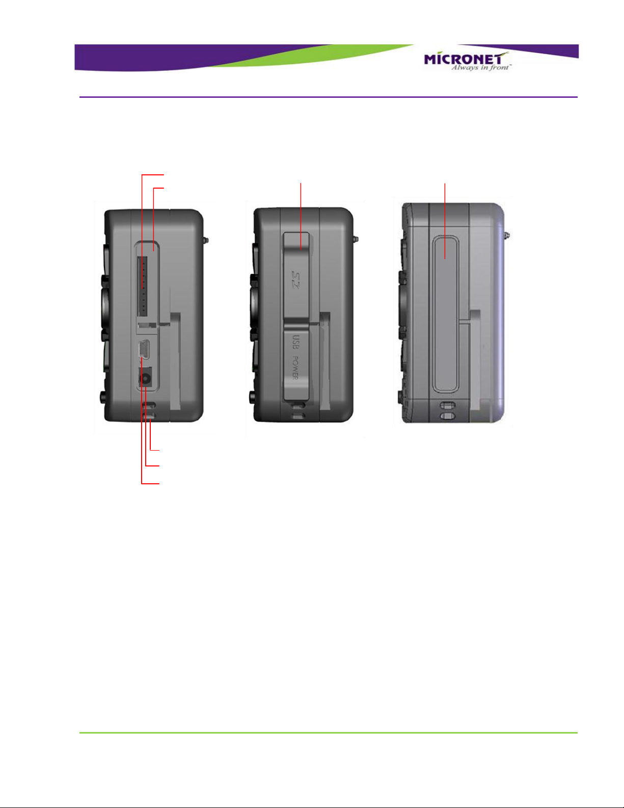
CCEE--5500XX MMooddeell,, RRiigghhtt SSiiddee PPaanneell
Figure 4 – CE-50X Model, Right Side Panel (Device Connector Slot) and Slot cover components
Device connectors slot
USB OTG Port
5V Power-in connector
Device Connector Slot - Rubber and Plastic Covers
Memory Card Support
For more information on CE-50X Right side panel components, see:
Device connectors slot, on page 25
Memory Card Support, on page 24
USB OTG Port, on page 32
5V Power-in connector, on page 42
Device Connector Slot - Rubber and Plastic Covers, on page 25
, on page 69
Page 21
Introduction
CE-50X Device Components
GDUTUG500/01
CE-500 MDT Hardware Guide
21 / 97
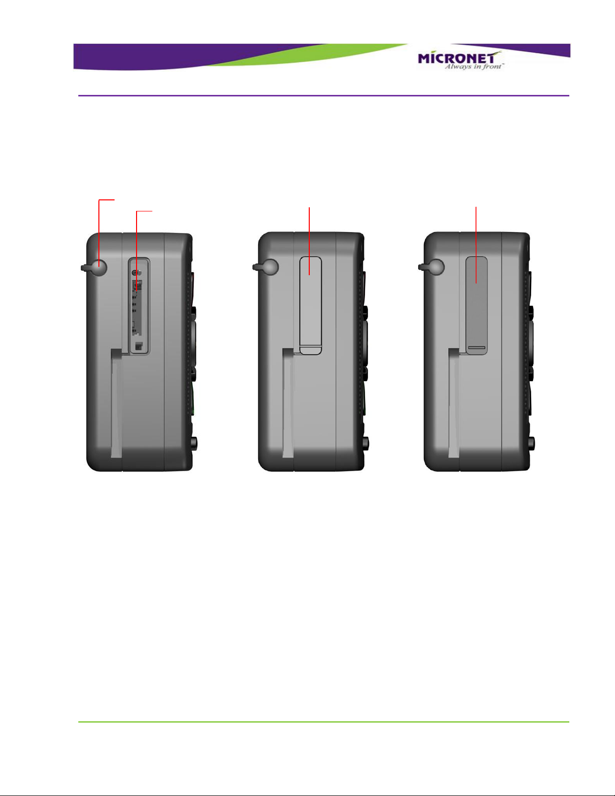
CCEE--5500XX MMooddeell,, LLeefftt SSiiddee PPaanneell CCoommppoonneenntt
Figure 5 – CE-50X Model, Left Side Panel and SIM Card Slot cover components
CCEE--5500XX MMooddeell,, RReeaarr PPaanneell CCoommppoonneennttss
SIM card slot
Stylus
Device Connector Slot - Rubber and Plastic Covers
Error! Reference source not found., on page Error! Bookmark not defined.
For more information on CE-50X Left side panel components, see:
SIM card slot , on page 53
Device Connector Slot - Rubber and Plastic Covers, on page 25
Stylus, on page 27
Page 22
Introduction
CE-50X Device Components
GDUTUG500/01
CE-500 MDT Hardware Guide
22 / 97
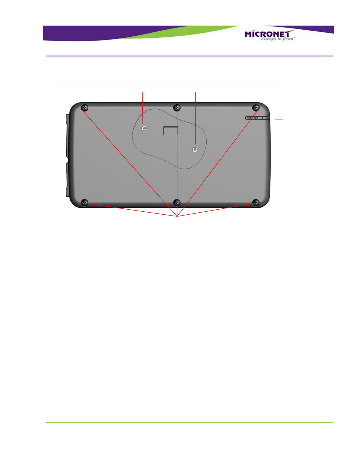
Figure 6 – CE-50X Model, Rear Panel components
Stylus
Mounting Arm screw inserts
Device assembly screws
For more information on CE-50X Rear panel components, see:
Mounting Arm screw inserts, on page 85
Stylus, on page 27
Page 23

Technical and Functional Details
Platform Core
GDUTUG500/01
CE-500 MDT Hardware Guide
23 / 97
2
2
T
Teecchhnniiccaall aanndd FFuunnccttiioonnaall
D
Deettaaiillss
PPllaattffoorrmm CCoorree
OOppeerraattiinngg SSyysstteemm
AApppplliiccaattiioonn DDeevveellooppmmeenntt EEnnvviirroonnmmeenntt
The CE-500 platform is powered by Windows CE 6.0 with the Core license. Optionally, you can upgrade
to the Professional license at additional cost.
For details on supported operating system components, refer to CE-500 Operating System Specifications
at http://www.micronet.co.il/CE-500_Operating_system.html
For more details on device’s operating system architecture, refer to the CE-500 Software Developer's
Guide.
The CE-500 platform supports Microsoft Visual Studio 2005 or 2008 and C++ (Win32 API) or Microsoft
.NET Compact Framework 3.5.
Micronet Development Toolkit (DTK) includes the following components:
Full Micronet SDK
Application samples
Device management and upload tools
Development accessories
Documentation
Page 24

Technical and Functional Details
Platform Core
GDUTUG500/01
CE-500 MDT Hardware Guide
24 / 97
PPrroocceessssoorr
RRAAMM
FFllaasshh MMeemmoorryy
NOTE:
To prevent uncontrolled power cut-off situations that can cause significant Flash File
System damage, verify that you provide proper power connection to the device. For more
details, see
Power Management, page 46.
MMeemmoorryy CCaarrdd SSuuppppoorrtt
For more details on development infrastructure, product tolls, and DTK contents, refer to the CE-500
Getting Started Guide.
TI OMAP3503
High-performance Superscalar ARM Cortex™-A8
The device provides a total of 256 MB of RAM memory (DDR type), which is partially allocated for
system and application usage.
Approximately 64 MB of the RAM memory is allocated for the system. The remaining memory is
allocated for RAM storage or application usage (user configurable).
The CE-500 provides 512 MB of Flash Memory (NAND type). This memory is partially allocated for
system image storage and Flash File System partition accessible for the applications as a persistent data
storage drive.
Approximately 64 MB of the Flash memory is allocated for system image. The remaining memory is
allocated for data storage.
Because the registry is hive-based, the operating system registry is also stored on the Flash File System
drive.
The device provides an MMC / SD card slot with the following parameters:
HC-MMC / SD cards (SDHC) complaint MMC System Specification V4.2 and SD I/O Cards
Specification V2.0
SD memory cards up to 32GB size support FAT16 / FAT32 Active disk
Page 25

Technical and Functional Details
User Interface
GDUTUG500/01
CE-500 MDT Hardware Guide
25 / 97
DDeevviiccee CCoonnnneeccttoorr SSlloott -- RRuubbbbeerr aanndd PPllaassttiicc CCoovveerrss
RReeaall TTiimmee CClloocckk ((RRTTCC))
WWaattcchhddoogg
NOTE:
This feature is used for the automatic solution recovery. However, Flash File System
corruption problems can occur if executed during file saving operation.
Speed: x133
Clocks: Identification mode – 400 kHz, data mode 20 MHz
The MMC / SD (SDHC) card slot is located on the right side panel. By default, a user can physically
access the slot. The platform supports two access protection options. For more details, see the following
section.
The CE-500 device has a rubber cover that protects the SD card slot, 5V Power-In connector, USB OTG
connector and the SIM card slot from water and dust (for example, when the device is used in the
portable mode out of a vehicle). You must close the cover in any of these conditions.
To prevent access to the connectors, a permanent plastic cover option is available. This cover replaces
the rubber cover. To replace the rubber cover with the plastic one:
1. Remove the rubber cover by removing the rubber snap in the center of the cover.
2. Push the plastic cover into the same place.
After the plastic cover is inserted, this cover can only be broken (physically) by an external mechanical
tool to access the card
The platform provides a Real Time Clock (RTC) that continuously operates even when the device is
powered off, but still connected to a vehicle or an internal battery.
In addition, RTC enables powering on the device based on a predefined alarm.
To monitor mission-critical processes, the platform provides an intelligent watchdog mechanism. This
mechanism provides various capabilities for programming automatic reset of the terminal. The watchdog
mechanism can be configured to control application stability and restart the device if an application or
system hangs or freezes.
For more details on proper use of the watchdog mechanism, refer to the Developers Guide.
Page 26

Technical and Functional Details
User Interface
GDUTUG500/01
CE-500 MDT Hardware Guide
26 / 97
UUsseerr IInntteerrffaaccee
DDiissppllaayy
TToouucchh SSccrreeeenn aanndd SSttyylluuss
The mechanical architecture of the platform enables support of various types and sizes of user interface.
The CE-500’s user interface is an entirely independent module, which is connected to the device’s core
layer.
The platform currently supports two types of the user interface:
7” display based - CE-507 device model
4.3” display based - CE-504 device model
A type of the user interface type automatically detected during system startup.
The required user interface type (device model) must be specified while ordering the device.
The user interface model can be ordered separately as well (for field upgrade by a technician). For field
installation of the CE-500 user interface modules, see page 93.
The CE-504 device model provides a 4.3” Touch Color display with WQVGA (480 X 272 pixels)
resolution.
The CE-507 device model provides a 7” Touch Color display with WVGA (800 X 480 pixels) resolution.
Both models are based on the transflective TFT LCD technology, provide the high contrast display,
support 16M colors, and provide a multi-level white LED backlight with a typical luminous intensity of
400 cd/m2.
The platform enables developers to change the display mode to set up the landscape or portrait
orientation programmatically. In addition, developers can enable the automatic change of the display
mode based on a cradle state signal. Developers can use this ability to manage how applications are
displayed in vehicle and out-of-cab operations.
The device display provides an analog-resistive-technology-based touch screen overlay that supports a
minimum of one million times of knocking life.
Page 27

Technical and Functional Details
User Interface
GDUTUG500/01
CE-500 MDT Hardware Guide
27 / 97
SSttyylluuss
NOTE:
To prevent touch screen overlay damage, do not contact the exposed polarizer with
anything harder than a device stylus. To clean dust off the display surface, gently wipe it
with cotton, chamois, or any other soft material.
To decrease the wear of the touch screen overlay, specify your software application
architecture to use device keys to enable the most commonly used application functions.
LLiigghhtt SSeennssoorr
KKeeyyppaadd
A plastic stylus is mounted on the rear panel for the convenience of signature capture or other touch
screen operations.
The platform provides a light sensor component, which is located on the front panel. Applications use
this sensor to recognize light and dark working modes, as well as device backlight adjustments.
The system provides a function of configurable automatic keypad and display backlight adjustments
based on the light sensor status. For more details on light sensor, refer to the Developers Guide.
The CE-500 device provides integrated rubber keys for convenience and safety operation. The Elastomer
rubber tactile keypad includes all of the following:
4 directions (Up, Down, Left, and Right)
3 controls (Accept, Decline, and Push)
4 (CE-504 model) or 12 (CE-507 model) menu keys
Page 28
Technical and Functional Details
User Interface
GDUTUG500/01
CE-500 MDT Hardware Guide
28 / 97
Figure 7 – CE-504 Model, Control, direction and Menu Keys disposition
Control and Direction Keys
Menu keys F1 F2 F3 F4
Decline
Up
Left
Push
Right
Down
Accept
Page 29
Technical and Functional Details
User Interface
GDUTUG500/01
CE-500 MDT Hardware Guide
29 / 97
Figure 8 – CE-507 Model, Control, direction and Menu Keys disposition
Up
Right
Down
Left
Push
Menu
Keys
F1
F2
F3
F4
F5
F6
Menu
Keys
F7
F8
F9
F10
F11
F12
Control and Direction Keys
Decline
Accept
The menu (function) “F” keys are located near the device display as indicators for the relevant functions
displayed on the screen.
All the keys are backlit and can be configured to provide system audio feedback during use.
The platform provides a function of “rotating” the direction keys to support both landscape and portrait
display modes. The automatic adjustment can be configured to switch the keys based on the Cradle
indication signal. Developers can use this ability to manage how applications are displayed and
controlled in vehicle and out-of-cab device operations.
Page 30
Technical and Functional Details
Audio Support
GDUTUG500/01
CE-500 MDT Hardware Guide
30 / 97
CCuussttoommiizzeedd FFrroonntt PPaanneell LLaabbeell ((OOppttiioonn))
AAuuddiioo SSuuppppoorrtt
IInntteerrnnaall SSppeeaakkeerrss
You can connect an additional external keyboard using the device’s USB host port connection, if
required.
Micronet provides the ability to attach a customized front panel label based on your specifications. To
enable you to rebrand the terminal's front panel, Micronet will provide graphic files and size
specifications. This is subject to an additional charge per unit based on quantity. Once printed, Micronet
will store the labels and use them for orders placed for this product.
Figure 9 – Customized Front Panel Label
The CE-500 device provides two 1W / 8Ω integrated speakers, which are located on the front panel. The
speakers are connected to the stereo channel of the platform audio CODEC and provide a nominal of 90
dB @ 0.1m volume.
The internal speakers and internal microphone (which is described in the next section) enables using the
device as a hands-free voice calls device in parallel to its general functionality. This capability can be
used with the internal or external voice-enabled modem option.
Page 31

Technical and Functional Details
Communication Interfaces
GDUTUG500/01
CE-500 MDT Hardware Guide
31 / 97
IInntteerrnnaall MMiiccrroopphhoonnee
AAuuddiioo CCOODDEECC ((OOppttiioonn))
CCoommmmuunniiccaattiioonn IInntteerrffaacceess
SSeerriiaall CCoommmmuunniiccaattiioonn
NOTES:
The Windows OS is not specified as a real time OS. Thus, it is highly recommended to
implement a flow control functionality using the serial communication to guarantee a
strong and stable communication flow of your application.
SSeerriiaall PPoorrtt 11 ((CCOOMM11))
External speakers and other audio device connections are supported by the optional platform's audio
module. For more information, see External Audio Module on page 57.
The platform provides an integrated high-sensitive microphone, which is located on the front panel. The
microphone supports voice calls along with optional voice recognition and recording engines.
An external microphone and other audio device connections are supported by the optional platform's
audio module. For more information, see External Audio Module on page 57.
The platform provides a multi-channel audio CODEC that supports and manages all basic and optional
platform audio components. Developers can control internal and external speakers, microphones, and
Bluetooth and GSM voice functions using the API. When setting up these components, dedicated CODEC
channels are used to manage audio components, including system sound, voice calls, optional text-to-
speech, and voice recognition engines.
The platform provides two serial communication ports for external devices and peripheral connections.
These ports support various hardware and software flow control functions.
The platform provides a serial communication port at the EIA-Rs232 level. The port is connected to the
Main Terminal “Con1” connector, which is located on the bottom panel of the device. This port supports
a 300 to 115,200bps baud rate and provides one pair of communication-control handshake signals (CTS
/ RTS).
Generally, Serial Port 1 operates as a main system serial port for modem or AVL box communication.
Page 32

Technical and Functional Details
Communication Interfaces
GDUTUG500/01
CE-500 MDT Hardware Guide
32 / 97
SSeerriiaall PPoorrtt 22 ((CCOOMM22))
UUSSBB ((UUnniivveerrssaall SSeerriiaall BBuuss)) CCoommmmuunniiccaattiioonn
UUSSBB OOTTGG PPoorrtt
For the disposition map of the signals of this port on Main Terminal “Con1” Connector, see page 38.
In the Fixed-mount mode, this port requires the Main Accessory Cable connection. For the disposition
map of the signals of this port on the Main Accessory Cable, see Accessories Main Interface cable COM1
Connector, on page 61.
For the disposition map of the signals of this port on the Device Cradle, see Device Cradle connectors
COM1 Connector, on page 76.
Serial Port 2 is a second Rs232 port. The port is connected to the Enhanced terminal “Con2” connector.
This port supports a 300 to 115,200bps baud rate and only provides the TX and RX signals.
For the disposition map of the signals of this port on Enhanced Terminal “Con2” Connector, see page 39.
In the Fixed-mount mode, this port requires Enhanced Accessory Cable connection. For the disposition
map of the signals of this port on the Enhanced Accessory Cable, see Accessories Enhanced Interface
cable COM2 Connector, on page 65.
For the disposition map of the signals of this port on the Device Cradle, see Device Cradle connectors
COM2 Connector, on page 78.
The platform provides two USB communication ports for external devices and peripheral connections.
The USB Host interface supports the following profiles:
USB Standard HID
USB Printer (PCL)
USB Storage
The USB Client (Device) interface supports Microsoft Active Sync for application development and device
management using the USB OTG port described below.
The USB "On The Go" Communication port is connected to the USB OTG connector, which is located on
the right panel of the device.
This port can operate either as the USB Host or USB Client interface. Depending on the connected
device type, the required interface is automatically recognized and enabled.
Page 33

Technical and Functional Details
Communication Interfaces
GDUTUG500/01
CE-500 MDT Hardware Guide
33 / 97
NOTE:
The USB OTG port is limited to provide up to 100mA of power consumption for non-self
powered client devices.
UUSSBB HHoosstt PPoorrtt
NOTE:
The USB Host port is limited to provide up to 100 mA of power consumption for non-self
powered client devices.
The USB Client functionality of this port is used to connect the CE-50X terminal to host devices, such as
PC or Notebook. Microsoft Active Sync protocol is implemented in the platform to support a variety of:
Microsoft Windows CE device configuration
Management tools
Application development
Debugging purposes.
In addition, the USB Client functionality is used by certain Micronet tools for device uploading and
management during the boot mode.
The USB Host functionality of this port is used to connect the CE-50X terminal to USB Client devices,
including USB keyboard and memory steak.
The USB OTG port supports USB2.0 - low, full, and high speeds of communication standard.
The USB OTG connector type is – Mini-AB Female.
The USB Host communication port is connected to the Main Terminal “Con1” connector, which is located
on the bottom panel of the device. This port supports USB2.0 - low, full, and high speeds of
communication standard.
For the disposition map of the signals of this port on Main Terminal “Con1” Connector, see page 38.
In the Fixed-mount mode, this port requires Main Accessory Cable connection. For the disposition map
of the signals of this port on the Main Accessory Cable, see Accessories Main Interface cable USB
Connector, on page 62.
Page 34

Technical and Functional Details
Peripheral Controls
GDUTUG500/01
CE-500 MDT Hardware Guide
34 / 97
EEtthheerrnneett CCoommmmuunniiccaattiioonn ((OOppttiioonn))
NOTE:
Other optional modular-platform features can be separately ordered and installed by the
customer. However, this option can only be included in the device by Micronet during
device manufacturing and cannot be added afterward. You must specify the Ethernet
option requirement with the device order.
PPeerriipphheerraall CCoonnttrroollss
DDiiggiittaall II//OO
DDiiggiittaall IInnppuuttss
For the disposition map of the signals of this port on the Device Cradle, see Device Cradle connectors
USB Connector, on page 77.
The platform optionally provides the Ethernet LAN communication port, connected to the Enhanced
terminal “Con2” connector, which is located on the bottom panel of the device. The Ethernet LAN
communication is a factory set option.
This port is fully compliant with IEEE 802.3 / 802.3u standards and supports 10BASE-T and 100BASE-TX
functionalities.
For the disposition map of the signals of this port on Enhanced Terminal “Con2” Connector, see page 39.
In the Fixed-mount mode, this port requires Enhanced Accessory Cable connection. For the disposition
map of the signals of this port on the Accessory Enhanced interface Cable, see LAN Connector, on page
66.
For the disposition map of the signals of this port on the Device Cradle, see Device Cradle Enhanced
cradle Connectors
LAN Connector, on page 78.
The platform provides two digital inputs at the automotive voltage level for monitoring and controlling
external peripherals or sensor signals. These signals are connected to the Main Terminal “Con1” and
“Con2” connectors, which are located on the bottom panel of the device.
Page 35

Technical and Functional Details
Peripheral Controls
GDUTUG500/01
CE-500 MDT Hardware Guide
35 / 97
NOTE:
One of these inputs (In1) is also used to power on the device from the shutdown state.
For proper power management implementation, the input must be connected to the
vehicle's ignition switch. The platform provides various software control options for this
essential feature. For more details, refer to the Digital I/O and Power Management
sections of the Developers Guide.
Input State
Typical
Minimum
Maximum
Low
0V
-30V
5V
High
12V-24V
+8V
+30V
DDiiggiittaall OOuuttppuutt
Parameter
Value
Maximum switchable voltage
+VIN
Maximum switchable current
300mA
Table 2 – Electrical Parameters of Input States
The platform provides a digital output (Open Collector) for external peripherals control. This signal is
connected to the Main Terminal “Con1” connector, which is located on the bottom panel of the device.
Table 3 – Electrical Parameters of Open Collector Output
For the disposition map of the Digital Input1 and Digital Output signals of this port on Main Terminal
“Con1” Connector, see page 38.
For the disposition map of the Digital Input2 signal of this port on Enhanced Terminal “Con2” Connector,
see page 39.
In the Fixed-mount mode, the Digital Input1 and Digital Output require the Main Accessory Cable and
Digital Input2 requires the Enhanced Accessory Cable connection.
For the disposition map of the Digital Input1 and Digital Output on Power-Adaptor-Box of the Main
Accessory Cable, see Power-Adaptor-Box to +Vin Connector, on page 64.
For the disposition of the Digital Input2 signal on the Accessory Cables Enhanced Interface cable, see
COM2 Connector, on page 65.
For the disposition map of the Digital Input1 and Digital Output on the Device Cradle, see +Vin
Connector, on page 76.
For the disposition of the Digital Input2 signal on the Device Cradle, see COM2 Connector, on page 78.
Page 36

Technical and Functional Details
Peripheral Controls
GDUTUG500/01
CE-500 MDT Hardware Guide
36 / 97
AAnnaalloogg IInnppuutt
11--WWiirree IInntteerrffaaccee
The platform provides an analog input signal to monitor the voltage range of compatible vehicle sensors,
such as an analog fuel gauge. This signal is connected to the Main Terminal “Con1” connector, which is
located on the bottom panel of the device.
The supported voltage range is from 0V to 30V.
For the disposition map of this signal on Main Terminal “Con1” Connector, see page 38.
In the Fixed-mount mode, this port requires the Enhanced Accessory Cable connection. For the
disposition map of the signals of this port on the Accessory Cable Enhanced Interface cable, see COM2
Connector, on page 65.
For the position of this signal on the Device Cradle, see COM2 Connector, on page 78.
The platform provides the 1-Wire Interface Port connected to the Main Terminal “Con1” connector,
which is located on the bottom panel of the device.
This port provides control, signaling, and power over a single-wire connection. Developers can connect
an optional touch probe accessory and use Dallas ID Memory DS1990A 64 bit ID Buttons for
identification and authorization control. See http://www.maxim-
ic.com/products/ibutton/ibuttons/memoryoverview.cfm
For the disposition map of this signal on Enhanced Terminal “Con2” Connector, see page 39.
In Fixed-mount mode, this port requires the Enhanced Accessory Cable connection. For the disposition
map of the signals of this port on the Accessory Cables Enhanced Interface cable, see COM2 Connector,
on page 65.
For the position of this signal on the Device Cradle, see COM2 Connector, on page 78.
Page 37

Terminal Connector Signal Maps
Peripheral Controls
GDUTUG500/01
CE-500 MDT Hardware Guide
37 / 97
3
3
T
Teerr
m
miinnaall
C
Coonnnneeccttoorr
S
Siiggnnaall
M
Maappss
OOvveerrvviieeww
This chapter describes the Basic (“Con1” and “Con2”) and Full (“Con3” and “Con4”) connectors
configuration. The power, communication and I/O signals in the Basic configuration, and the Video,
CANBus and Audio signals in the Full configuration.
All pins are ESD protected (against electrostatic discharge).
All the “shield” pins of the connectors are attached to the Ground signal.
The following abbreviations are used in this chapter:
I - Input signal
O - Output signal
B - Bus signal
V - Voltage signal
G – Ground
All the four connectors' type is Molex HandyLink™ I/O Interconnect System part number - 0448281162.
Page 38

Terminal Connector Signal Maps
Peripheral Controls
GDUTUG500/01
CE-500 MDT Hardware Guide
38 / 97
PPiinnoouutt ooff CCoonnnneeccttoorrss
MMaaiinn TTeerrmmiinnaall
“
“
CCoonn1
1
”
”
CCoonnnneeccttoorr
Figure 10 – “Con1” Connector Pinout
Pin
Signal
Type
Function
Specifications
1
+5Vin
V
MDT Power Supply Voltage
+ 5V
2
GND
G
MDT Power Supply Ground
3
+5Vin
V
MDT Power Supply Voltage
+5V
4
GND
G
MDT Power Supply Ground
5
Dig_In1
I
Digital Input 1 (Ignition
switch)
Typical Min
Max
Input Low: VIL 0V -30V
6V
Input High: VIH 12V-24V +8V
+30V
6
Dig_Out1
O
Digital Output 1
Open Collector
Max. switchable current = 300mA
Max. switchable voltage = +VIN
Max. saturation voltage = 0.6V
7
M_Control 1
--
Micronet accessories control
signal
This signal is for Micronet-embedded
accessory-control purposes only.
Do not connect anything to this pin.
8
TXD1
O
Transmit Data (COM1)
EIA-RS232 level
9
RXD1
I
Receive Data (COM1)
EIA-RS232 level
Pin 1 Pin 16
"Con1" Connector
Table 4 – Main Terminal “Con1” Connector Signal Map
Page 39

Terminal Connector Signal Maps
Peripheral Controls
GDUTUG500/01
CE-500 MDT Hardware Guide
39 / 97
Pin
Signal
Type
Function
Specifications
10
RTS1
O
Request To Send (COM1)
EIA-RS232 level
11
CTS1
I
Clear To Send (COM1)
EIA-RS232 level
12
DGND
G
Digital Ground
13
USB +5V
V
5V USB Power Out
+5V±10%; 500mA max.
14
USB D+
B
USB Data (+)
Universal Serial Bus Specification
Rev 2.
15
USB D-
B
USB Data (-)
Universal Serial Bus Specification
Rev 2.
16
USB GND
G
USB Ground
EEnnhhaanncceedd TTeerrmmiinnaall
“
“
CCoonn2
2
”
”
CCoonnnneeccttoorr
Figure 11 – “Con2” Connector Pinout
Pin
Signal
Type
Function
Specifications
1
An_In1
I
Analog Input
0V-30V max, 12k OHM
2
AGND
G
Analog Ground
3
TXD2
O
Transmit Data
(COM2)
EIA-RS232 level
4
RXD2
I
Receive Data
(COM2)
EIA-RS232 level
Pin 1 Pin 16
"Con2" Connector
Table 5 – Enhanced Terminal “Con2” Connector Signal Map
Page 40

Terminal Connector Signal Maps
Peripheral Controls
GDUTUG500/01
CE-500 MDT Hardware Guide
40 / 97
Pin
Signal
Type
Function
Specifications
5
Dallas
I/O
One-Wire
Interface.
(DALLAS ID
Button Interface)
Port
6
Dig_In2
I
Digital Input 2
Typical Min Max
Input Low: VIL 0V -30V 6V
Input High: VIH 12V-24V +8V +30V
7
M_Control 2
--
Micronet
accessories
control signal
This signal is for Micronet embedded
accessories control purposes only.
Do not connect anything to this pin.
8
M_Control 3
--
Micronet
accessories control
signal
This signal is for Micronet-embedded accessorycontrol purposes only.
Do not connect anything to this pin.
9
M_Control 4
--
Micronet
accessories control
signal
This signal is for Micronet-embedded accessorycontrol purposes only.
Do not connect anything to this pin.
10
M_Control 5
--
Micronet
accessories control
signal
This signal is for Micronet-embedded accessorycontrol purposes only.
Do not connect anything to this pin.
11
M_Control 6
--
Micronet
accessories control
signal
This signal is for Micronet-embedded accessorycontrol purposes only.
Do not connect anything to this pin.
12
DGND
G
Digital Ground
13
LAN_TX+
I
Optional – Ethernet
LAN Transmit Data
+
IEEE 802 3/802 3u Standards
14
LAN_TX-
I
Optional – Ethernet
LAN Transmit Data -
IEEE 802 3/802 3u Standards
15
LAN_RX+
O
Optional – Ethernet
LAN Receive Data +
IEEE 802 3/802 3u Standards
16
LAN_RX-
O
Optional – Ethernet
LAN Receive Data -
IEEE 802 3/802 3u Standards
Page 41

Terminal Connector Signal Maps
Peripheral Controls
GDUTUG500/01
CE-500 MDT Hardware Guide
41 / 97
OOppttiioonnaall EExxtteerrnnaall VViiddeeoo aanndd CCAANNBBuuss
“
“
CCoonn3
3
”
”
CCoonnnneeccttoorr
Figure 12 – “Con3” Connector Pinout
Pin
Signal
Type
Function
Specifications
To be documented
OOppttiioonnaall EExxtteerrnnaall AAuuddiioo
“
“
CCoonn4
4
”
”
CCoonnnneeccttoorr
Figure 13 – “Con4” Connector Pinout
Pin
Signal
Type
Function
Specifications
To be documented
Pin 1 Pin 16
"Con3" Connector
Pin 1 Pin 16
"Con4" Connector
Table 6 –Video and CANBus Terminal “Con3” Connector Signal Map
Table 7 –Audio Terminal “Con4” Connector Signal Map
Page 42

Platform Power
Peripheral Controls
GDUTUG500/01
CE-500 MDT Hardware Guide
42 / 97
4
4
P
Pllaattffoorr
m
m
P
Poo
w
weerr
OOvveerrvviieeww
55VV PPoowweerr--iinn ccoonnnneeccttoorr
Figure 14 – Device 5V Power-in connector
MMaaiinn TTeerrmmiinnaall
“
“
CCoonn1
1
”
”
55VV ppoowweerr ccoonnnneeccttoorr
5V Power-in connector
The CE-50X device is powered by a 5V DC power source. The device power-in signals (+VIN and GND)
are connected in parallel to two entities:
Located on the device right side panel
Located on the device bottom panel
Page 43

Platform Power
Peripheral Controls
GDUTUG500/01
CE-500 MDT Hardware Guide
43 / 97
Figure 15 –Device Main Terminal “Con1” connector
VVeehhiiccllee BBaatttteerryy CCoonnnneeccttiioonn
NOTE:
The CE-50X device has no internal fuse, and therefore its connection to the vehicle's
power source line must be protected by a 10A fuse. Additionally, a 4A fuse must be added
to the power cable with an inline fuse holder for HHC / HHD blade-type fuses.
Main Terminal “Con1” connector
The platform provides various accessories that enable direct connection of the device to the 12V or 24V
vehicle battery.
During application development or when the device is performing in the Stand-alone mode, the device
can be powered through the Power-in connector by Wall (110V / 220V AC to 5V DC) or Vehicle Cigarette
Lighter (12V / 24V DC to 5V DC) power adaptors.
For Wall Power Adaptor specifications, see IDC Connector, on page 67.
For Vehicle Cigarette-Lighter power-adaptor cable specifications, see , on page 69.
When the device is mainly fixed-mounted in the vehicle or connected to the solution peripherals, the
device can be powered through the Terminal Connector, by the Main Interface Accessory cable, or
through the device Cradle when the device is portable.
For the disposition map of the device’s Power-In signals on Main Terminal “Con1” Connector, see page
38.
The CE-50X device can be directly connected to the vehicle battery using the Device Cradle or Main
Interface accessory cable.
The supported nominal battery voltage supply is 12V or 24V DC. The operating range is between 8V to
30V DC.
Page 44

Platform Power
Peripheral Controls
GDUTUG500/01
CE-500 MDT Hardware Guide
44 / 97
WARNING!
If you use a device that does not include the internal battery option, do not connect the
terminal power to the ignition switch signal. In this case, you prevent uncontrolled power
cut-offs, which may have a detrimental effect on the operating system.
The +Vin signals of the Cradle or Main Accessory cable Power Adaptor Box must be
directly connected to the Vehicle battery. To properly setup power management, you must
connect the Vehicle Ignition Switch signal to the digital input (In1) of the device. For more
information about the power management architecture of the platform, see
Power Management on page 46.
WARNING!
DO NOT USE another battery type!
Risk of explosion if an incorrect battery is used instead of the original battery supplied by
Micronet.
NOTE:
Connecting the power to the CE-50X device does not enable the device. Only pressing
the Push key or signal rise on the device digital input 1, enables the device from the
power-down state.
If your solution requires device enabling consequently to the power connection, connect
(shorten) the digital Input1 pin with the power-in signal.
IInntteerrnnaall BBaatttteerryy ((OOppttiioonn))
In the Fixed mount mode, the vehicle power connection requires the Main Accessory Cable connection.
For the disposition of the +12V / 24V Vin and Ground signals on the Power–Adaptor-Box of the Main
Accessory Cable, see Power-Adaptor-Box to +Vin Connector, on page 64.
For the position +12V / 24V Vin and Ground signals on the Device Cradle, see +Vin Connector, on page
76.
The platform provides an internal battery pack option to:
Support the device functionality in the Portable mode
Provide power backup in main power source disconnect situations
This option is categorized as a Modular Platform option so it can be included with the device upon
delivery by Micronet as well as to be ordered separately. For more details about the Modular option
architecture, see CE-500 Platform Optional Modules, on page 15.
3000 mAh Lithium-Polymer-based battery is available.
Page 45

Platform Power
Peripheral Controls
GDUTUG500/01
CE-500 MDT Hardware Guide
45 / 97
NOTE:
The operating temperature range of the CE-50X device including the battery option is
limited to 14 °F to 140 °F (-10°C to +60°C). The system automatically recognizes out-ofrange situations and stops the operation to prevent battery degradation.
DDeevviiccee PPoowweerr CCoonnssuummppttiioonn
Operation Mode
CE-504 Model -
Current Consumption
CE-507 Model -
Current Consumption
Shut-down
To be documented
To be documented
Suspend
To be documented
To be documented
Idle (no application activity)
To be documented
To be documented
Active (with full backlight and wireless communication)
To be documented
To be documented
Maximum
To be documented
To be documented
The platform’s system manages automatic power management and battery recharging control to
provide a most effective battery service. However, the developers of portable applications need to:
Consider the power limitations of this mode
Provide accurate management of significant power consumer features, such as: wireless
communication interfaces, voice enabled solutions, and so on
The operation time of the device while powered by the internal battery is directly dependent on the
device configuration and application performance. Nevertheless, the estimated time of continued
operation for standard applications is ~2 hours.
Micronet delivers the battery pack charged for 40% of capacity. In this case, the shelf lifetime of the
pack is about six months. If you did not use the battery during this period, you must recharge the
battery up to 40% of capacity again to continue the storage. CE-50X devices provide a software utility
that charge the battery pack up to 40%. For more details on this utility, refer to the Internal Battery
section of the Developers Guide.
Before you begin to use the battery, you must to fully charge the battery pack by connecting a power
source to the device until the End Of Charge indication.
Table 8 – Device Current Consumption Parameter Table
Page 46

Power Management
Overview
GDUTUG500/01
CE-500 MDT Hardware Guide
46 / 97
5
5
P
Poo
w
weerr
M
Maannaaggee
m
meenntt
OOvveerrvviieeww
UUnnddeerrssttaannddiinngg PPoowweerr SSttaatteess
SSuussppeenndd
The CE-500 system provides smart power management during the device operation. The power
management capabilities include power states management, performance adjustment, automatic
backlight, and additional power consumer control.
Using the power management capabilities is especially helpful when the device is powered by the
internal battery or connected to the vehicle battery while the ignition switch is off. Most of this
functionality is transparent to application developers. However, the rest is configurable and the
developer can adjust it for specific usages. For more information on the CE-500 platform power-
management architecture, refer to “Power Management” section in the Developers Guide.
The OS registry can be resets to factory defaults. For more information on setting the registry to factory
default, refer to "Setting Registry to factory default" paragraph below.
The Flash memory storage partition can be formatted. For more information on formatting the Flash
memory storage, refer to "Formatting flash Memory Storage" paragraph below.
The following states explain characteristics of the power states and events that trigger the device to
enter to, and exit from, each state.
Developers can define whether or not the device switches to the Suspend state upon pressing the
Accept button using the Control Panel.
State characteristics:
Page 47

Power Management
Understanding Power States
GDUTUG500/01
CE-500 MDT Hardware Guide
47 / 97
NOTE:
These events resume all processes from the same point when the device switched to
Suspended.
SShhuuttddoowwnn
Registry is flushed, settings are preserved
RTC is alive
Memory allocation is preserved
Triggers to Enter the State:
Pressing and holding Accept key for 3 seconds
Calling the API function
System Power management timeouts
Triggers to Exit the State:
Pressing Push key
RTC alarm notification
Digital Input 1 signal
Inserting the device to cradle
Figure 16 – Device manual software Suspend
Developers can define whether or not the device switches to the Shutdown state upon pressing the
Decline button using the Control Panel.
Page 48

Power Management
Understanding Power States
GDUTUG500/01
CE-500 MDT Hardware Guide
48 / 97
WWaarrmm BBOOOOTT rreesseett
State characteristics:
Registry is flushed, settings are preserved
RTC is alive
Memory allocation is not preserved
Triggers to Enter the State:
Pressing and holding the Decline key for 3 seconds
Calling the API function
Triggers to Exit the State:
Pressing Push key
RTC alarm notification
Digital Input 1 signal
Figure 17 – Device manual software Shutdown
State characteristics:
Registry is flushed, settings are preserved
RTC is alive
Memory allocation is preserved
Triggers to Enter the State:
Pressing and holding F1, F2 and Up for 1 second
Calling the API function
Page 49

Power Management
Understanding Power States
GDUTUG500/01
CE-500 MDT Hardware Guide
49 / 97
HHaarrddwwaarree PPoowweerr DDoowwnn
NOTE:
This Hardware Power Down state is for a storage purposes only. The RTC is not kept and
Memory allocation resets to factory settings.
Figure 18 – Device manual Warm BOOT Reset
A Shelf storage power down state for a battery operated CE-500 device.
State characteristics:
Registry is flushed, settings are preserved
RTC is not alive (system time is reset)
Memory allocation is not preserved
Triggers to Enter the State:
Pressing F1, F2, and Up keys for 5 seconds
Calling the API function
Triggers to Exit the State:
Pressing Push key
Page 50

Power Management
Setting Registry to Factory Defaults
GDUTUG500/01
CE-500 MDT Hardware Guide
50 / 97
WARNING!
It is highly recommended not using the Warm BOOT and Power Down. A technician or
developer can perform these operations for troubleshooting purposes only.
This operation must not be activated while the application is saving data to the Flash
storage because it may damage the Flash File system.
SSeettttiinngg RReeggiissttrryy ttoo FFaaccttoorryy DDeeffaauullttss
Figure 19 – Device manual power down
To reset the registry to factory default, follow the steps:
Shutdown the CE-500 device first by pressing the Decline key for 3 seconds
Pressing and holding simultaneously F2, Up and Down keys
Pressing the Push key while holding the F2, Up and Down keys for 3 seconds
The OS resets the registry and the Stylus calibration screen appears.
Figure 20 – Reset Registry to Factory default
Page 51

Power Management
Formatting Flash Memory Storage
GDUTUG500/01
CE-500 MDT Hardware Guide
51 / 97
FFoorrmmaattttiinngg FFllaasshh MMeemmoorryy SSttoorraaggee
To format the Flash memory storage partition, follow the steps:
Shutdown the CE-500 device first by pressing the Decline key for 3 seconds
Pressing and holding simultaneously F2, Left and Right keys
Pressing the Push key while holding the F2, Left and Right keys for 3 seconds
The OS resets the registry and the Stylus calibration screen appears.
Figure 21 – Format the Flash Memory partition
Page 52

Optional Feature Modules
Overview
GDUTUG500/01
CE-500 MDT Hardware Guide
52 / 97
6
6
O
Oppttiioonnaall FFeeaattuurree
M
Moodduulleess
OOvveerrvviieeww
W
Wiirreelleessss CCoommmmuunniiccaattiioonn
OOvveerrvviieeww
GGSSMM // GGPPRRSS
Due to the specific mechanical and electronic architecture of the CE-500 device, many optional features
are implemented as independent physical modules. You can either order these modules with the device
or order them separately and install on an existing device later. Installation of modules requires basic
technical skills and must be implemented according to Micronet instructions.
For field installation of the CE-500 Optional Feature Modules Installation, see page 93.
The optional direct interface modules require certain accessory cables for connection in the Fixed-device
operation mode, or enhanced device cradle in the Fixed / Mobile operation mode.
The CE-500 platform provides a variety of optional wireless communication modules that enable solution
communication service, GPS position control, and peripheral-device support.
All wireless modules are provided with internal antennas. These antennas were specifically developed
and tuned for the CE-500 device architecture. The antennas provide high sensitivity and performance for
both in-vehicle environment and the portable device mode.
The CE-500 platform provides an optional GSM / GPRS Cellular Modem module that enable wireless
communication between the device and any server or back-office application.
Page 53

Optional Feature Modules
Wireless Communication
GDUTUG500/01
CE-500 MDT Hardware Guide
53 / 97
SSIIMM ccaarrdd sslloott
NOTE:
The GSM / GPRS option is a significant power consumer of the platform. If your solution
requires Portable operation including cellular communication, consider the Enhanced
battery option while specifying your device configuration.
Based on the Telit GE864-Quad Automotive embedded cellular modem, this module provides the
following features:
Voice and data communication support
GPRS Multi-slot Class 10
Quad band 850 / 900 / 1800 / 1900 MHz
Output power:
- Class4 (2W) @ 850 / 900 MHz
- Class1 (1W) @ 1800 / 1900 MHz
Sensitivity:
- 107 dBm @ 850 / 900 MHz
- 106 dBm @ 1800 / 1900 MHz
Controlled via AT commands according to GSM 07.05, 07.07 and Telit enhancements
Serial port multiplexer (GSM 7.10) support
The CE-500 system provides automatic GPRS communication management capabilities as well as direct
access to the modem communication channel (AT commands) and control functions. For more details on
GSM / GPRS communication software management, refer to the Developers Guide.
Developers can implement the voice functionality of the module using the integrated device speakers
and microphone. In addition, developers can use the optional external audio module for external
microphone and speaker connections. Bluetooth headset connection is supported for voice call
implementation by the optional Bluetooth module of the CE-500 device.
The internal modem option requires a SIM card connection. The SIM card slot is located on the left side
panel of the device. Two types of SIM-card-slot mechanical covers are provided for card protection:
Rubber cover that allows the end-user access to the SIM card during operation
Plastic cover that prevents SIM card access from the end-user. Once inserted, after the SIM card
installation it can only be broken (physically) by an external mechanical tool to expose the card.
Page 54

Optional Feature Modules
Wireless Communication
GDUTUG500/01
CE-500 MDT Hardware Guide
54 / 97
GGPPSS
The CE-500 platform provides an optional GPS receiver module, which is especially suited for navigation
applications and traffic reports.
Based on the u-Blox NEO-5D high-performance embedded-GPS receiver, this module features u-Blox
SuperSense® Indoor GPS technology that offers unmatched tracking performance in harsh signal
environments, such as parking lots and dense urban environments.
The GPS module provides the following features:
50-channel u-Blox 5 engine with over 1 million effective correlators
Under 1 second Time-To-First-Fix for Hot and Aided Starts
Supports SBAS (WAAS, EGNOS, MSAS, GAGAN)
SuperSense® Indoor GPS: -160 dBm tracking sensitivity
Position Accuracy:
- Autonomous < 2.5 m
- SBAS < 2.0 m
High immunity to jamming
Protocols support:
- NMEA Input / output, ASCII, 0183, 2.3 (compatible to 3.0)
- UBX Input / output, binary, u-Blox proprietary
Supports AssistNow Online and AssistNow Offline A-GPS services; OMA SUPL compliant
The GPS module designed to support the GALILEO system, which is currently being developed by
European authorities. The capability of receiving GALILEO L1 signals will provide increased coverage and
even better positioning accuracy.
The CE-500 system supports a Microsoft GPS locator engine for automatic GPS data management as
well as direct access to the receiver communication port and control functions. For more details on GPS
receiver software management, refer to the Developers Guide.
Page 55

Optional Feature Modules
Wireless Communication
GDUTUG500/01
CE-500 MDT Hardware Guide
55 / 97
WWiirreelleessss LLAANN aanndd BBlluueettooootthh CCllaassss22
OOvveerrvviieeww
NOTE:
The Wireless LAN and Bluetooth capability is a significant power consumer of the
platform. If your solution requires Portable operation of the CE-500 device including
cellular communication, consider the Enhanced battery option while specifying your
device configuration.
WWiirreelleessss LLAANN OOppeerraattiioonn
BBlluueettooootthh OOppeerraattiioonn
The CE-500 platform provides an optional combined Wireless Local Area Network (IEEE 802.11) and
Bluetooth (Class2) communication module. The Wireless LAN communication is especially suited to high-
speed data transfer over the air, when the Wireless LAN hotspot infrastructure is provided. For
applications that require huge data transactions, Wireless LAN is the most economical way to implement
the solution. Bluetooth communication is used for the Bluetooth-enabled connections with peripherals,
such as mobile phone, audio headset, and printer.
The CE-500 Wireless LAN and Bluetooth Class2 module adopts Marvell’s latest highly-integrated WLAN
and Bluetooth SoC - 88W8688.
The module is compliant with the IEEE 802.11b/g standard and uses DSSS (Direct Sequence Spread
Spectrum), OFDM (Orthogonal Frequency Division Multiplexing), DBPSK, DQPSK, CCK, and QAM
baseband modulation technologies.
In addition to the support of WPA / WPA2, WEP 64-bit, and 128-bit encryption, the module supports the
IEEE 802.11i security standard. The module supports this standard through the implementation of AES
(Advanced Encryption Standard), CCMP (Counter Mode CBC-MAC Protocol), and WEP with TKIP security
mechanisms.
The module also supports IPSec with DES / 3DES / ASE encryption and MD5 / SHA-1 authentication.
For the Chinese market, the module supports WAPI specifications.
For video, voice, and multimedia applications, the AW-GH381 supports 802.11e QoS (Quality of
Service).
The module is Bluetooth 2.1+EDR (Enhanced Data Rate) compliant.
Page 56

Optional Feature Modules
Wireless Communication
GDUTUG500/01
CE-500 MDT Hardware Guide
56 / 97
WWiirreelleessss LLAANN aanndd BBlluueettooootthh CCllaassss22 MMoodduullee SSppeecciiffiiccaattiioonnss
Functions
Specifications
WLAN Standard
IEEE 802.11b/g, Wi-Fi compliant
Bluetooth Standard
Bluetooth 2.1+EDR (Enhanced Data Rate)
Major Chipset
Marvell 8688
Frequency Range
2.4 GHz ISM radio band
Number of Channels
- 802.11b: USA, Canada and Taiwan – 11
- Most European Countries – 13
- France – 4, Japan – 14
- 802.11g: USA, Canada and Taiwan – 11
- Most European Countries – 13
- Japan – 13
Modulation
- DSSS, OFDM, DBPSK, DQPSK, CCK, 16 QAM, 64-QAM for WLAN
- GFSK (1Mbps), Π/4 DQPSK (2Mbps) and
8DPSK (3Mbps) for Bluetooth
Output Power
WLAN:
- 802.11b(Ch1~13): typical 15dBm +/- 2dBm
- 802.11b(Ch14): typical 10dBm +/- 2dBm
- 802.11g: typical 12dBm +/- 2dBm
The CE-500 system supports the following Bluetooth communication profiles:
SPP [Service (Serial) Port Profile]
LAP (LAN Access Profile, applicable in professional license only)
PAN (Personal Area Networking) Profile
GAP (Generic Access Profile) TBD
GOEP (Generic Object Exchange Profile) TBD
HCRP (Hardcopy Cable Replacement Profile) TBD
DUN (Dial-Up Network) Profile TBD
FTP (File Transfer Profile) TBD
HID (Human Interface Device) Profile TBD
HFP (Hands-Free Profile) TBD
HSP (Headset Profile) TBD
OPP (Object Push Profile) TBD
Table 9 – Wireless LAN and Bluetooth Class2 Module Specifications
Page 57

Optional Feature Modules
Peripheral Interfaces
GDUTUG500/01
CE-500 MDT Hardware Guide
57 / 97
Functions
Specifications
Bluetooth:
- Bluetooth Class 2: typical 1dBm+/- 2dBm
Receive Sensitivity
WLAN:
- 802.11b: typical -87dBm at 11Mbps
- 802.11g: typical -70dBm at 54Mbps
Bluetooth:
- GFSK: typical -87dBm
- Π/4 DQPSK: typical -88dBm
- 8DPSK: typical -81dBm
Medium Access Protocol
CSMA / CA with ACK
Data Rates
WLAN:
- 802.11b: 1, 2, 5.5, 11Mbps
- 802.11g: 6, 9, 12, 18, 24, 36, 48, 54Mbps
Bluetooth:
- Bluetooth 2.1+EDR data rates of 1,2, and
3Mbps
Operating Range
- Open Space: ~300m; indoor: ~100m for
WLAN
- Minimum 10m indoor for Bluetooth
- The transmission speed may vary according
to environment
Security
H/W TKIP processing
part of 802.11i security standard
Co-Existence
Bluetooth and cell phone (GSM / DCS / WCDMA / UMTS / 3G) coexistence
PPeerriipphheerraall IInntteerrffaacceess
CCAANNBBuuss ((JJ11993399))
EExxtteerrnnaall AAuuddiioo MMoodduullee
To be documented
To be documented
Page 58

Optional Feature Modules
Additional Integrated Options
GDUTUG500/01
CE-500 MDT Hardware Guide
58 / 97
EExxtteerrnnaall VViiddeeoo MMoodduullee
AAddddiittiioonnaall IInntteeggrraatteedd OOppttiioonnss
AAcccceelleerroommeetteerr
To be documented
To be documented
Page 59

Platform Accessories
Accessory Cables
GDUTUG500/01
CE-500 MDT Hardware Guide
59 / 97
7
7
P
Pllaattffoorr
m
m
A
Acccceessssoorriieess
AAcccceessssoorryy CCaabblleess
Optionally, the CE-500 platform provides accessory cables for connection of device signals in the Fixed-
mounted operation mode. All cables are connected to device terminal connectors, which are located on
the bottom panel. All of these cables use the same type of a connector.
However a mechanical “key“ is implemented on each connector cover to prevent the connection of an
incorrect cable to an incorrect device connector. A mechanical cable fixing option supported by the
screw inserts is located near each terminal connector. Main and Enhanced accessory cables support
connectivity of signals that are provided by the basic device configuration. Therefore, these connectors
always exist on the device panel. Additional accessory cables are used to support optional platform
features and require the relevant optional device module.
The pinout and types of the interface connectors provided by the accessory cables are similar to those
for the CE-500 Device Cradle (they both have the same purposes).
In addition to the interfaces that require the standard type of connector (such as USB and Ethernet), the
remaining device signals are implemented on the cables or the Cradle by Molex Micro-Fit 3.0™ Plug type
of connectors. For implementing the connectivity, use the opposite (receptacle) type of connector with
the relevant amount of pins for each peripheral interface. This is the Molex 43025 Series type of
connector. Use the Molex Micro-Fit 3.0™ Crimp Terminal Female for the wiring. Ensure that the correct
wire size (AWG) for each signal is according to the requirements of the cable-connector Signal Maps
specifications.
Type for all Device connectors of accessory cables – Molex HandyLink™ I/O Interconnect System
Molex part number – 0453391600
Page 60

Platform Accessories
Accessory Cables
GDUTUG500/01
CE-500 MDT Hardware Guide
60 / 97
Figure 22 – Terminal Connector Pinout
NOTE:
The device terminal connectors are located at different rotation angles.
Figure 23 – Accessory Connectors, Bottom Panel
Video and CANBus Interface
Cable
Audio Interface Cable
Cable mounting
screw inserts
Main Interface Cable
Enhanced Interface Cable
All shield pins of the connectors are attached to the Ground signal.
The length of each accessory cable is 1.5 meter.
For more information on CE-500 front panel components, see:
Main Interface Cable, on page 61
Enhanced Interface Cable, on page 65
Video and CANBus Interface Cable, on page 67
Audio Interface Cable, on page 67
Cable mounting screw inserts, on page 59
Page 61

Platform Accessories
Accessory Cables
GDUTUG500/01
CE-500 MDT Hardware Guide
61 / 97
MMaaiinn IInntteerrffaaccee CCaabbllee
MMaaiinn IInntteerrffaaccee CCaabbllee CCoonnnneeccttoorrss SSiiggnnaall MMaapp
CCOOMM11 CCoonnnneeccttoorr
COM1
PWR
USB
Device connector
The Main interface cable must be attached to the “Con1” terminal connector of the device.
This cable is provided with an integrated power adaptor box. This box converts the vehicle 12V or 24V
power signal to 5V, as required by the device.
Figure 24 – Main Interface Cable
Connector type - Molex Micro-Fit 3.0™ 6 pin plug
Table 10 – Main Interface Cable COM1 Connector Signal Map
Figure 25 – COM1 Connector Pinout
Page 62

Platform Accessories
Accessory Cables
GDUTUG500/01
CE-500 MDT Hardware Guide
62 / 97
Pin
Signal
Function
Wire Size
(AWG) Required
1
TXD1
Transmit Data (COM1)
28
2
RTS1
Request To Send (COM1)
28
3
DGND
Digital Ground
28
4
RXD1
Receive Data (COM1)
28
5
CTS1
Clear To Send (COM1)
28
6
N/C
Not connected
UUSSBB CCoonnnneeccttoorr
Pin
Signal
Function
1
USB +5V
5V USB Power Out
2
USB D+
USB Data (+)
3
USB D-
USB Data (-)
4
USB GND
USB Ground
PPoowweerr--AAddaappttoorr--BBooxx CCoonnnneeccttoorr
WARNING!
The Power-Adaptor-Box connector on the main cable interface must be connected only to
the power adaptor box. Do not connect anything else to these signals!
Connector type - USB type-A female
Table 11 – USB Connector Signal Map
Figure 26 – Main Interface Cable USB Connector Pinout
Page 63

Platform Accessories
Accessory Cables
GDUTUG500/01
CE-500 MDT Hardware Guide
63 / 97
Figure 27 – Power-Adapter-Box Connector Pinout
PPoowweerr AAddaappttoorr BBooxx
WARNING!
Metal 'Power Adapter Box' is installed for installation in a restricted access location.
PPoowweerr--AAddaappttoorr--BBooxx ttoo CCEE--550000 CCoonnnneeccttoorr
WARNING!
Only the Power-Adaptor-Box Connector of the main interface cable must be attached to
this connector. Do not connect anything else to these signals.
The power adaptor box converts the 12V/24V power signal to 5V DC, which the device's main cable
accepts.
Figure 28 – Power Adapter Box
Page 64

Platform Accessories
Accessory Cables
GDUTUG500/01
CE-500 MDT Hardware Guide
64 / 97
PPoowweerr--AAddaappttoorr--BBooxx ttoo ++VViinn CCoonnnneeccttoorr
IMPORTANT
The 12V or 24V and Ground signals of the vehicle battery and the ignition switch signal
must be attached to this connector.
Figure 30 – Power-Adapter-Box to MDT Connector Pinout
Pin
Signal
Type
Function
Specifications
Wire Size (AWG)
Required
1
Dig_In1
I
Digital Input 1 (Ignition
switch)
Typical Min Max
Input Low: VIL 0V -30V 6V
Input High: VIH 12V-24V +8V +30V
28
2
Dig_Out1
O
Digital Output 1
Open Collector
Max. switchable current = 300mA
Max. switchable voltage = +VIN
Max. saturation voltage = 0.6V
28
3
GND
G
MDT Power Supply Ground
24
4
+VIN
V
MDT Power Supply Voltage
Typical Min Max
+12V / 24V +8V +30V
24
Figure 29 – Power-Adapter-Box to MDT Connector
Connector type - Molex Micro-Fit 3.0™ 4 pin plug
Table 12 – Power Adaptor Box +Vin Connector Signal Map
Page 65

Platform Accessories
Accessory Cables
GDUTUG500/01
CE-500 MDT Hardware Guide
65 / 97
EEnnhhaanncceedd IInntteerrffaaccee CCaabbllee
EEnnhhaanncceedd IInntteerrffaaccee CCaabbllee ccoonnnneeccttoorrss SSiiggnnaall MMaapp
CCOOMM22 CCoonnnneeccttoorr
Figure 32 – Enhanced Interface Cable COM2 Connector Pinout
Pin
Signal
Function
Wire Size (AWG)
Required
1
TXD2
Transmit Data (COM2)
28
2
Dallas
One-Wire Interface. (DALLAS ID Button Interface) Port
28
COM2
Reserve
LAN
Device connector
The Enhanced interface cable must be attached to the “Con2” terminal connector of the device.
Figure 31 – Enhanced Interface Cable
Connector type - Molex Micro-Fit 3.0™ 8 pin plug
Table 13 – Enhanced Interface Cable COM2 Connector Signal Map
Page 66

Platform Accessories
Accessory Cables
GDUTUG500/01
CE-500 MDT Hardware Guide
66 / 97
Pin
Signal
Function
Wire Size (AWG)
Required
3
Dig_In2
Digital Input 2
28
4
N/C
Not connected
5
RXD2
Receive Data (COM2)
28
6
DGND
Digital Ground
28
7
An_In1
Analog Input
28
8
AGND
Analog Ground
28
LLAANN CCoonnnneeccttoorr
NOTE:
The Ethernet LAN interface is an optional platform feature. The interface signals described
below present on this connector only if the device supports these signals. Otherwise, the
connector pins are not connected and must not be used.
Pin
Signal
Function
Wire Size (AWG)
Required
1
LAN_TX+
Ethernet LAN Transmit Data +
24
2
LAN_TX-
Ethernet LAN Transmit Data -
24
3
LAN_RX+
Ethernet LAN Receive Data +
24
4
N/C
Not connected
Connector type –RJ45
Table 14 – Enhanced Interface Cable LAN Connector Signal Map
Figure 33 – Enhanced Interface Cable LAN Connector Pinout
Page 67

Platform Accessories
Power Supply adaptors
GDUTUG500/01
CE-500 MDT Hardware Guide
67 / 97
Pin
Signal
Function
Wire Size (AWG)
Required
5
N/C
Not connected
6
LAN_RX-
Ethernet LAN Receive Data -
24
7
N/C
Not connected
8
N/C
Not connected
MM__CCoonnttrrooll11 CCoonnnneeccttoorr
VViiddeeoo aanndd CCAANNBBuuss IInntteerrffaaccee CCaabbllee
AAuuddiioo IInntteerrffaaccee CCaabbllee
PPoowweerr SSuuppppllyy aaddaappttoorrss
IIDDCC CCoonnnneeccttoorr
This connector can only be used for the specified Micronet-accessory devices connection. Do not connect
anything else to these signals.
To be documented
To be documented
Figure 34 – M_Control1 Connector Pinout
An IDC connector wall power supply adapter (110V / 220V AC to 5V DC) for connecting to the CE-500
5V power-in connector on the right panel slot (For office usage, available in DTK only).
Page 68

Platform Accessories
GDUTUG500/01
CE-500 MDT Hardware Guide
68 / 97
Figure 35 – IDC Wall mount adapter
NOTE:
External power Charger for the unit must be LPS(Limited power sources).
MMoolleexx 4433002255 SSeerriieess CCoonnnneeccttoorr
Figure 36 – Molex 43025 connector Wall mount adapter
NOTE:
External power Charger for the unit must be LPS(Limited power sources).
A Molex 43025 series connector wall power supply adapter (110V / 220V AC to 12V DC) for connecting
to the CE-500 Main Interface cable DC to DC convertor, or to the Basic and Enhanced Cradle models
(For office usage, available in DTK only).
Page 69

Platform Accessories
GDUTUG500/01
CE-500 MDT Hardware Guide
69 / 97
IInntteerrffaaccee SSuuppppoorrtt
JJ11770088 CCoonnvveerrttoorr BBooxx
RRSS--442222 CCoonnvveerrttoorr BBooxx
To be documented
To be documented
Page 70

Device Cradle
Overview
GDUTUG500/01
CE-500 MDT Hardware Guide
70 / 97
8
8
D
Deevviiccee
C
Crraaddllee
OOvveerrvviieeww
NOTE:
The pinout and types of interface connectors that are provided with the Device Cradle
are similar to those for the same purposes by the relevant CE-500 Accessory Cable.
Optionally, the CE-500 platform provides the Device Cradle. The Cradle is used for mechanical mounting
and electronic connectivity of the device in solutions that require Fixed and Portable operations.
The Device Cradle is fixed-mounted in a vehicle cabin, and all electronic interfaces are connected to the
Cradle “Interface” connectors, which are located on the rear panel. All signals connected to Cradle
”Interface” connectors are transparently connected to the Cradle “Device” connectors, which correctly
meet the device's “Terminal” connectors when the device is placed in the Cradle. When the device is
removed from the Cradle, the device can continue to operate using the internal battery. However, the
device loses connectivity to the Cradle interface connections.
Two models of the Device Cradle are available:
Basic, which provides two Cradle “Device” “Con1” and “Con2” connectors with the correct “Interface”
connectors. The Basic model supports all interface connections provided with the basic configuration
of the CE-500 device.
Enhanced, which provides additional “Device” “Con3” and “Con4” connectors with the relevant
“Interface” connectors that support additional optional features of the device. These optional features
are required for implementing the additional interfaces.
The CE-500 Device Cradle supports both CE-504 and CE-507 device models.
For the Device Cradle Electrical and Mechanical installation instructions, see Device Installation on page
83.
Page 71

Device Cradle
CE-500 Device Basic Cradle Components
GDUTUG500/01
CE-500 MDT Hardware Guide
71 / 97
CCEE--550000 DDeevviiccee BBaassiicc CCrraaddllee CCoommppoonneennttss
Figure 37 – CE-500 Device Basic Cradle, Front Side
Release knob
Main Terminal “Con1” Connector
Lock snap
Enhanced Terminal “Con2” Connector
For more information on Basic Cradle front panel components, see:
Main Terminal “Con1” Connector, on page 38
Enhanced Terminal “Con2” Connector, on page 39
Release knob and Lock snap, on page 91
Page 72

Device Cradle
CE-500 Device Basic Cradle Components
GDUTUG500/01
CE-500 MDT Hardware Guide
72 / 97
Figure 38 – CE-500 Device Basic Cradle, Rear Panel
+Vin Connector
COM1 Connector
USB Connector
Mounting Arm screw inserts
Cables holding handle
Release knob
M_Control1 Connector
COM2 Connector
LAN connector
For more information on Basic Cradle rear panel components, see:
+Vin Connector, on page 76
LAN connector, on page 78
COM1 Connector, on page 76
USB Connector, on page 77
COM2 Connector ,on page 78
Mounting Arm screw inserts, on page 85
Page 73

Device Cradle
CE-500 Device Enhanced Cradle Components
GDUTUG500/01
CE-500 MDT Hardware Guide
73 / 97
CCEE--550000 DDeevviiccee EEnnhhaanncceedd CCrraaddllee CCoommppoonneennttss
Figure 39 – CE-500 Device Enhanced Cradle, Front Side
Enhanced Terminal
“Con2” Connector
Optional External Audio
“Con4” Connector
Optional External Video and CANBus
“Con3” Connector
Lock snap
Release knob
Main Terminal
“Con1” Connector
For more information on Enhanced Cradle front panel components, see:
Main Terminal “Con1” Connector, on page 38
Enhanced Terminal “Con2” Connector, on page 39
Optional External Video and CANBus “Con3” Connector, on page 41
Optional External Audio “Con4” Connector, on page 41
Release knob and Lock snap, on page 91
Page 74

Device Cradle
CE-500 Device Enhanced Cradle Components
GDUTUG500/01
CE-500 MDT Hardware Guide
74 / 97
Figure 40 – CE-500 Device Enhanced Cradle, Rear Panel
COM1 Connector
+Vin Connector
USB Connector
Video-in1 connector
Video-in2 connector
LAN connector
COM2 Connector
Spare Connector
Right speaker connector
Left speaker connector
Mounting Arm screw inserts
Audio-in connector
Cables holding handle
Release knob
Audio-out connector
CANBus connector
M_Control1 Connector
Microphone connector
For more information on Enhanced Cradle rear panel components, see:
+Vin Connector, on page 76
LAN connector, on page 78
COM1 Connector, on page 76
Page 75

Device Cradle
Device Cradle Connectors
GDUTUG500/01
CE-500 MDT Hardware Guide
75 / 97
DDeevviiccee CCrraaddllee CCoonnnneeccttoorrss
OOvveerrvveeww
USB Connector, on page 77
COM2 Connector ,on page 78
Video-in1 connector, on page 80
Microphone connector, on page 81
Left speaker connector, on page 81
M_Control1 Connector, on page 79
Video-in2 connector, on page 80
Audio-out connector, on page 80
Audio-in connector, on page 81
Right speaker connector, on page 81
CAN Bus connector, on page 82
Mounting Arm screw inserts, on page 85
Instead of the interfaces that require the standard type of connectors (such as USB and Ethernet), all
other signals are located on the CE-500 Device Cradle by Molex Micro-Fit 3.0™ Plug connector types. To
implement the connectivity, use the opposite (Receptacle) type of connector with the correct amount of
pins for each peripheral interface. This is Molex 43025 Series type of connectors. Use the Molex Micro-
Fit 3.0™ Crimp Terminal Female for wiring. Ensure that the correct wire size (AWG) for each signal is
according to the requirements of the interface-connector Signal Maps specifications.
Type of all device connectors of the Cradle - Molex HandyLink™ I/O Interconnect System
Molex part number - 0455931600
Figure 41 – Device Cradle Connector Pinout
Page 76

Device Cradle
Device Cradle Connectors
GDUTUG500/01
CE-500 MDT Hardware Guide
76 / 97
NOTE:
The terminal connectors of the device are located at different rotation angles.
BBaassiicc ccrraaddllee ccoonnnneeccttoorrss
++VViinn CCoonnnneeccttoorr
Figure 42 – Cradle +Vin Connector Pinout
Pin
Signal
Type
Function
Specifications
Wire Size (AWG)
Required
1
Dig_In1
I
Digital Input 1 (Ignition switch)
Typical Min Max
Input Low: VIL 0V -30V 6V
Input High: VIH 12V-24V +8V +30V
28
2
Dig_Out1
O
Digital Output 1
Open Collector
Max. switchable current = 300mA
Max. switchable voltage = +VIN
Max. saturation voltage = 0.6V
28
3
GND
G
MDT Power Supply Ground
24
4
+VIN
V
MDT Power Supply Voltage
Typical Min Max
+12V / 24V +8V +30V
24
CCOOMM11 CCoonnnneeccttoorr
All “shield” pins of the connectors are attached to the ground signal.
The 12V or 24V and Ground signals of the vehicle-battery as well as the ignition switch signal must be
attached to this connector.
Connector type - Molex Micro-Fit 3.0™ 4 pin plug
Table 15 – Cradle +Vin Connector Signal Map
Connector type - Molex Micro-Fit 3.0™ 6 pin plug
Page 77

Device Cradle
Device Cradle Connectors
GDUTUG500/01
CE-500 MDT Hardware Guide
77 / 97
Figure 43 – Cradle COM1 Connector Pinout
Pin
Signal
Function
Wire Size (AWG) Required
1
TXD1
Transmit Data (COM1)
28
2
RTS1
Request To Send (COM1)
28
3
DGND
Digital Ground
28
4
RXD1
Receive Data (COM1)
28
5
CTS1
Clear To Send (COM1)
28
6
N/C
Not connected
UUSSBB CCoonnnneeccttoorr
Figure 44– Cradle USB Connector Pinout
Pin
Signal
Function
1
USB +5V
5V USB Power Out
2
USB D+
USB Data (+)
3
USB D-
USB Data (-)
4
USB GND
USB Ground
Table 16 – Cradle COM1 Connector Signal Map
Connector type – USB type-A Female
Table 17 – Cradle USB Connector Signal Map
Page 78

Device Cradle
Device Cradle Connectors
GDUTUG500/01
CE-500 MDT Hardware Guide
78 / 97
CCOOMM22 CCoonnnneeccttoorr
Figure 45 – Cradle COM2 Connector Pinout
Pin
Signal
Function
Wire Size (AWG)
Required
1
TXD2
Transmit Data (COM2)
28
2
Dallas
One-Wire Interface (DALLAS ID Button Interface)
Port.
28
3
Dig_In2
Digital Input 2
28
4
N/C
Not connected
5
RXD2
Receive Data (COM2)
28
6
DGND
Digital Ground
28
7
An_In1
Analog Input
28
8
AGND
Analog Ground
28
EEnnhhaanncceedd ccrraaddllee CCoonnnneeccttoorrss
LLAANN CCoonnnneeccttoorr
Connector type – Molex Micro-Fit 3.0™ 8 pin plug
Table 18 – Cradle COM2 Connector Signal Map
Connector type – RJ45
Page 79

Device Cradle
Device Cradle Connectors
GDUTUG500/01
CE-500 MDT Hardware Guide
79 / 97
Figure 46 – Cradle LAN Connector Pinout
Pin
Signal
Function
Wire Size (AWG)
Required
1
LAN_TX+
Optional – Ethernet LAN Transmit Data +
24
2
LAN_TX-
Optional – Ethernet LAN Transmit Data -
24
3
LAN_RX+
Optional – Ethernet LAN Receive Data +
24
4
N/C
Not connected
5
N/C
Not connected
6
LAN_RX-
Optional – Ethernet LAN Receive Data -
24
7
N/C
Not connected
8
N/C
Not connected
NOTE:
The Ethernet LAN interface is an optional feature of the platform. The interface signals
are only presented on this connector if supported by the device. Otherwise, this
connector pins are not connected and must not be used.
MM__CCoonnttrrooll11 CCoonnnneeccttoorr
Table 19 – Cradle LAN Connector Signal Map
This connector can only be used for specified Micronet accessory-device connections. Do not connect
anything else to these signals.
Page 80

Device Cradle
Device Cradle Connectors
GDUTUG500/01
CE-500 MDT Hardware Guide
80 / 97
Figure 47 – Cradle M_Control1 Connector
VViiddeeoo--iinn11 aanndd VViiddeeoo--iinn22 CCoonnnneeccttoorrss
Figure 48 – Cradle RCA Video Connector
NOTE:
The External Video interface support is an optional feature of the platform. This
interface signals are only located on this connector if supported by the device. In other
cases, this connector pins are not connected and must not be used.
AAuuddiioo--OOuutt CCoonnnneeccttoorr
Figure 49 – Cradle Audio Jack Connector
To be documented
This connector is provided by the enhanced Device Cradle model only.
To be documented
This connector is provided by the Enhanced Device Cradle model only.
Page 81

Device Cradle
Device Cradle Connectors
GDUTUG500/01
CE-500 MDT Hardware Guide
81 / 97
NOTE:
The External Audio interfaces support is an optional feature of the platform. This
interface signals are located on this connector only if the device supports these signals.
Otherwise, the connector pins are not connected and must not be used.
AAuuddiioo--IInn CCoonnnneeccttoorr
NOTE:
The External Audio interfaces support is an optional feature of the platform. This
interface signals are located on this connector only if the device supports these signals.
Otherwise, the connector pins are not connected and must not be used.
MMiiccrroopphhoonnee
Figure 51 – Cradle Microphone Jack Connector
NOTE:
The External Audio interfaces support is an optional feature of the platform. This
interface signals are only located on this connector if supported by the device. In other
cases, this connector pins are not connected and must not be used.
LLeefftt aanndd RRiigghhtt SSppeeaakkeerr CCoonnnneeccttoorrss
To be documented
This connector is provided by the enhanced Device Cradle model only.
To be documented
This connector is provided by the enhanced Device Cradle model only.
Figure 50 – Cradle Audio Jack Connector
This connector is provided by the enhanced Device Cradle model only.
Page 82

Device Cradle
Device Cradle Connectors
GDUTUG500/01
CE-500 MDT Hardware Guide
82 / 97
Figure 52 – Cradle Speakers Connector
NOTE:
The External Audio interfaces support is an optional feature of the platform. This
interface signals are located on this connector only if the device supports these signals.
Otherwise, the connector pins are not connected and must not be used.
CCAANNBBuuss CCoonnnneeccttoorr
Figure 53 – Cradle CANBus Connector Pinout
NOTE:
The CAN Bus interface is an optional feature of the platform. This interface signals are
located on this connector only if the device supports these signals. Otherwise, the
connector pins are not connected and must not be used.
To be documented
This connector is provided by the enhanced Device Cradle model only.
Page 83

Device Installation
Electrical Installation
GDUTUG500/01
CE-500 MDT Hardware Guide
83 / 97
9
9
D
Deevviiccee IInnssttaallllaattiioonn
EElleeccttrriiccaall IInnssttaallllaattiioonn
OOvveerrvviieeww
CCoonnnneeccttoorrss
Depending on the required operating mode of the solution, you can perform electrical installation
using device accessory cables (Fixed-mounted mode) or the device Cradle (Fixed-portable mode).
Both modes provide a similar connectivity type for each specific interface. For example, the Serial
port (COM1) of the device is on the Main accessory cable by a Molex Mini-Automotive 6 pin
receptacle connector type. The same type of connector with the same pinout is located on the rear
panel of the Cradle that provides this interface. This concept is relevant for all interface connectors.
In addition to interfaces that require the standard type of connector (such as USB and Ethernet), all
remaining device signals are located on the cables or Cradle by Molex Micro-Fit 3.0™ Plug connector
types.
To implement connectivity, use the opposite (Receptacle) type of connector with the correct amount
of pins for each peripheral interface. This is Molex 43025 Series type of connector. Use the Molex
Micro-Fit 3.0™ Crimp Terminal Female for wiring. Ensure the correct wire size (AWG) for each signal
according to Accessory cable requirements or Cradle-Connectors Signal-Map specifications.
Page 84

Device Installation
Mechanical Installation
GDUTUG500/01
CE-500 MDT Hardware Guide
84 / 97
EElleeccttrriiccaall IInnssttaallllaattiioonn PPrroocceedduurree
MMeecchhaanniiccaall IInnssttaallllaattiioonn
OOvveerrvviieeww
NOTE:
Mounting arm screws included only with Micronet mounting arm. Screws type and
dimension for other mounting arm provided below.
1. Prepare the Receptacle-connectors wiring connected to the required peripherals and power signals.
2. Connect the receptacle connectors to the Accessory cables or Cradle plug connectors.
3. Connect other peripherals with the standard interface connector types to the Accessory cables or
Cradle connectors.
4. Do one of the following depending on the mode:
In the Fixed-mounted mode, connect the Accessory cables to the CE-50X device terminal
connectors.
In the Fixed-portable mode, insert the CE-50X device into the device Cradle.
5. To power on the CE-50X device, press the Push button and verify that all connected peripheral
operate properly.
6. In the Fixed-mounted mode, fix the Accessory cables on the CE-50X device with cable mounting
screws.
The rear panels of the CE-50X device and CE-500 device Cradle provide a similar mechanical
infrastructure for mounting-stand (arm) installation. If a solution uses the Fixed-portable mode, the CE-
500 device Cradle must be fixed-mounted in the vehicle cabin using the mounting arm, when the device
is periodically attached and removed from it during operation.
In the Fixed-performing mode, the mounting arm is directly attached to the rear panel of the device
(details follow).
The mounting-arm screw-insert disposition is compatible with RAM® Mounts standard mounting-arm
types.
The Micronet mounting arm is also available.
Page 85

Device Installation
Mechanical Installation
GDUTUG500/01
CE-500 MDT Hardware Guide
85 / 97
NOTE:
This guide describes Terminal installation options that use the mounting arm only.
The in-vehicle installation instructions must be provided by a qualified installation
technician.
Pay special attention to mechanical strains when the detachable terminal options are used.
A correct installation location and surface must be chosen as along with installation
materials.
MMoouunnttiinngg AArrmm
Component Picture
Component Name
Mounting Arm stud ball
Arm parts
Screw nut
The Micronet CE-500 mounting arm is a flexible, rotating, arm-based mounting stand that provides a
wide range of fixed in-cabin positions for maximum comfort and visibility.
Table 20 – Mounting Arm Components
Figure 54 – CE-500 Mounting Arm
Page 86

Device Installation
Mechanical Installation
GDUTUG500/01
CE-500 MDT Hardware Guide
86 / 97
Component Picture
Component Name
Screw
Washer
Mounting Arm Base ball
Page 87

Device Installation
Mechanical Installation
GDUTUG500/01
CE-500 MDT Hardware Guide
87 / 97
FFiixxeedd--MMoouunntteedd DDeevviiccee IInnssttaallllaattiioonn
1. Determine the optimal positioning of the CE-50X device in the vehicle that provides easy access and
clear view.
2. Attach the base of the mounting-arm assembly to the dashboard or cabin.
3. Assemble the stand parts on the mounting-arm base.
4. Attach the mounting arm to the rear panel of the device using the mounting screws inserts.
5. Perform electrical installation. See Electrical Installation, on page 83
6. Install the CE-50X device on the mounting arm.
7. Adjust the optimal device position and fix it by closing the mounting-arm wing nut.
8. Arrange the cables using a plastic strip.
Figure 55 – Components for Fixed-Mounted Device Installation
Page 88

Device Installation
Mechanical Installation
GDUTUG500/01
CE-500 MDT Hardware Guide
88 / 97
MMoouunnttiinngg aarrmm ssccrreewwss ddiimmeennssiioonn
M4 Screw, 5mm depth
Proper screws for mounting non-Micronet mounting arm, based on the device inserts depth and the arm
stud ball.
Figure 56 – Device mounting inserts dimension
Page 89

Device Installation
Mechanical Installation
GDUTUG500/01
CE-500 MDT Hardware Guide
89 / 97
FFiixxeedd // PPoorrttaabbllee ((DDeevviiccee wwiitthh CCrraaddllee)) IInnssttaallllaattiioonn
1. Determine the optimal positioning of the CE-50X device in the vehicle that provides easy access and
clear view.
2. Attach the base of the mounting arm assembly to the dashboard or cabin.
3. Assemble the stand parts on the mounting arm base.
4. Attach the mounting arm to the rear panel of the device Cradle using the mounting screws inserts.
5. Perform electrical installation. See Electrical Installation, on page 83
6. Insert the device into the device cradle.
7. Install the device cradle onto the mounting arm.
8. Adjust the optimal device position and fix it by closing the mounting-arm wing nut.
9. Arrange the cables using a plastic strip and the optional protective rear cover of the cradle.
Figure 57 – Components for Fixed / Portable Device (Cradle) Installation
Page 90

Device Installation
Mechanical Installation
GDUTUG500/01
CE-500 MDT Hardware Guide
90 / 97
MMoouunnttiinngg aarrmm ssccrreewwss ddiimmeennssiioonn
M4 Screw, 7mm depth
Proper screws for mounting non-Micronet mounting arm, based on the cradle inserts depth and the arm
stud ball.
Figure 58 – Cradle mounting inserts dimension
Page 91

Device Installation
Mechanical Installation
GDUTUG500/01
CE-500 MDT Hardware Guide
91 / 97
IInnsseerrttiinngg tthhee DDeevviiccee iinnttoo tthhee CCrraaddllee
Figure 59 – Device insertion
To insert the device into the cradle:
1. Insert the device into the cradle slot from the top. Verify that the device tightly enters the slot
2. Pull down the device
Page 92

Device Installation
Mechanical Installation
GDUTUG500/01
CE-500 MDT Hardware Guide
92 / 97
RReemmoovviinngg tthhee DDeevviiccee ffrroomm tthhee CCrraaddllee
Figure 60 – Device Removal
To remove the device from the cradle:
1. To unlock the device, push and hold the Release knob on the bottom of the cradle.
2. Pull up the device from the cradle slot.
Page 93

Optional Feature Modules Installation
Mechanical Installation
GDUTUG500/01
CE-500 MDT Hardware Guide
93 / 97
1
1
0
0
O
Oppttiioonnaall FFeeaattuurree
M
Moodduulleess
IInnssttaallllaattiioonn
To be documented
Page 94

CE-500 Platform Physical Characteristics
Physical Characteristics
GDUTUG500/01
CE-500 MDT Hardware Guide
94 / 97
1
1
1
1
C
C
E
E--550000
P
Pllaattffoorr
m
m
P
Phhyyssiiccaall
C
Chhaarraacctteerriissttiiccss
PPhhyyssiiccaall CChhaarraacctteerriissttiiccss
Features
Details
CE-504 Dimensions & Weight
Width
6.30 inch
160 mm
Height
3.40 inch
87 mm
Depth
1.50 inch
38 mm
Weight (w Battery)
14.70 oz.
410 Gram
Weight (w/o Battery)
13.50 oz.
380 Gram
CE-507 Dimensions & Weight
Width
8.80 inch
225 mm
Height
6.40 inch
162 mm
Depth
2.10 inch
53 mm
Weight (w Battery)
25.80 oz.
730 Gram
Weight (w/o Battery)
24.70 oz.
700 Gram
Cradle Dimensions
Width
7.10 inch
180 mm
Height
3.50 inch
4.30 inch with release knob
90 mm
110 mm with release knob
Depth
2 inch
3.30 inch with protective cover
50 mm
85 mm with protective cover
Weight
7.80 oz.
9.50 oz. with protective cover
225 Gram
270 Gram with protective cover
Table 21 – Physical Characteristics
Page 95

Appendices
Appendix A
GDUTUG500/01
CE-500 MDT Hardware Guide
95 / 97
1
1
2
2
A
Appppeennddiicceess
AAppppeennddiixx AA
RReegguullaattiioonnss && CCeerrttiiffiiccaattiioonns
s
EEuurrooppeeaann MMaarrkkeett -- CCEE MMaarrkkiinngg ((CCllaassss BB))
We, Micronet Ltd.
Address: 27, Hametzuda st., Azor 58001, Israel.
Tel: +972-(0)3-5584884.
Certify and declare that the CE-500 Family were tested and found to comply with the harmonized
standards EN301 489-1,17, EN 300 328, EN60950-1, therefore comply with the essential
requirements of the R&TTE Directive and the LVD Directive.
The tests were done in ITL (Product Testing) LTD. in Israel.
The CE-500 Family (consists of CE-504, CE-507, power sources Comply (together & separately) with the
requirements of:
LVD Directive 2006/95/EC (73/23/EEC), According to standards:
EN60950-1
R&TTE Directive 1999/5/EC, According to standards:
EN301 489-1,17
EN300 328 (for Wi-Fi + Bluetooth Configuration)
Page 96

Appendices
Appendix A
GDUTUG500/01
CE-500 MDT Hardware Guide
96 / 97
Products labeled with symbol of crossed out wheeled bin need dispose
of according to your local regulations. Do not throw this product or its
accessories to into public garbage.
Please Contact your local distributor or municipality for more
information. This way, you make your contribution to protect our
environment and health.
FFCCCC RRuulleess ((CCllaassss AA))
The CE-500 Family Complies with the requirements imposed by the European Directive 2002/95/EC (and
its amendment) of the European Parliament and of the council of 27 January 2003 on the restriction of
the use of certain hazardous substances in electrical and electronic equipment (RoHS)
CFR 47, Part 15 Subpart B
CFR 47, Part 15 Subpart C (for Wi-Fi + Bluetooth configuration)
This equipment has been tested and found to comply with the limits for a Class A digital device,
pursuant to Part 15 of the FCC rules. These limits are designed to provide reasonable protection against
harmful interference in a residential installation. This equipment generates uses and can radiate radio
frequency energy and, if not installed and used in accordance with the instructions, may cause harmful
interference to radio communications. However, there is no guarantee that interference will not occur in
a particular installation. If this equipment does cause harmful interference to radio or television
reception, which can be determined by turning the equipment off and on, the user is encouraged to try
to correct the interference by one or more of the following measures:
a) Reorient or relocate the receiving antenna.
b) Increase the separation between the equipment and receiver.
c) Connect the equipment to an outlet on a circuit different from that to which the receiver is
connected.
Page 97

Appendices
Appendix A
GDUTUG500/01
CE-500 MDT Hardware Guide
97 / 97
IInnssttrruuccttiioonnss ccoonncceerrnniinngg hhuummaann eexxppoossuurree ttoo rraaddiioo ffrreeqquueennccyy eelleeccttrroommaaggnneettiicc ffiieellddss..
FCC Warning
Modifications not expressly approved by the manufacturer could void the
user authority to operate the equipment under FCC Rules.
FCC ID: U8ONB811
Model Name: CE-500 Family.
Trade Name: MDT (Mobile Data Terminal).
Responsible party: Micronet Ltd.
Address: 27, Hametzuda st., Azor, Israel.
Phone: +972-(0)3-5584884.
This device complies with Part 15 of the FCC Rules. Operating is subject to the following two
conditions: (1) This device may not cause harmful interference, and (2) This device accepts any
interference received. Including interference that may cause undesired operation.
d) Consult the dealer or an experienced radio/TV technician.
The FCC ID valid for the Devices configuration that includes Wi-Fi and Bluetooth module.
This device includes FCC ID: R17GE865 (Telit, GE-865), when contains GSM/GPRS feature.
Each device must be professionally installed in order to comply with section 15.203 of the FCC rules.
The user must use the recommended antenna, which specify in this guide in order to comply with the
FCC rules (but no more than the specified gain).
To comply with FCC Section 1.307 (b)(1) for human exposure to radio frequency electromagnetic fields,
implement the following instruction:
A distance of at least 20cm. between the equipment and all persons should be maintained during the
operation of the equipment.
 Loading...