

Page 1
Micronet SmartCAM™
Revision 1, September 2019
Vehicular Android Camera DVR and ADAS
(Advanced Driver Assistance System)
Hardware Guide
Micronet SmartCAM™
Rev. 1 Micronet SmartCAM™ - Hardware Guide 1 / 50
Page 2

Important Notice
© 2019 Micronet Ltd. All rights reserved.
Micronet Ltd. Reserves the right to alter the equipment specifications and descriptions in this publication
without prior notice. No part of this publication shall be deemed to be part of any contract or warranty
unless specifically incorporated by reference into such a contract or warranty.
The information contained herein is merely descriptive in nature and does not constitute a binding offer
for the sale of the product described herein.
All usage of Micronet Ltd. Logotype or trademarks is forbidden without prior written approval from
Micronet Ltd.
Information in this manual is subject to change without notice.
Micronet maintains no liability or responsibility to any person or entity concerning any loss or damage
arising from the information contained in this book.
Other company and brand products and service names are trademarks or registered trademarks of their
respective holders, for example, Google, Android, ADB, ADT, Eclipse and Android Studio.
Please refer to Micronet’s website (http://www.micronet-inc.com) for further information or contact us
directly (https://www.micronet-inc.com/contact/)
Rev. 1 Micronet SmartCAM™ - Hardware Guide 2 / 50
Page 3

Table of Contents
Table of Contents ....................................................................................................................... 3
Revision History ......................................................................................................................... 5
Safety Precautions ...................................................................................................................... 6
1. Introduction...................................................................................................................... 7
Micronet SmartCAM Platform Overview ....................................................................................... 7
In the Vehicle .......................................................................................................................... 7
Micronet SmartCAM Models ....................................................................................................... 8
Compatibility with Micronet SmartX Products ............................................................................... 9
Shorter Development Cycles ...................................................................................................... 9
Lower Total Cost of Ownership ................................................................................................... 9
GSD® Software Services ........................................................................................................... 9
Development Tool Kit .............................................................................................................. 10
Platform Key Feature Specifications .......................................................................................... 10
2. Micronet SmartCAM Views ............................................................................................... 11
Micronet SmartCAM Front View ................................................................................................ 11
Micronet SmartCAM Rear View ................................................................................................. 12
Micronet SmartCAM Top View .................................................................................................. 13
3. Micronet SmartCAM Functional Details ................................................................................... 14
Platform Core ........................................................................................................................ 14
User Interface ........................................................................................................................ 15
Cameras ............................................................................................................................... 16
Sound ................................................................................................................................... 16
Connectivity .......................................................................................................................... 16
Battery ................................................................................................................................. 18
Motion Control ....................................................................................................................... 19
Communication Interfaces ....................................................................................................... 19
General Purpose I/O ............................................................................................................... 20
Vehicle Bus Connectivity ......................................................................................................... 20
4. Micronet SmartCAM™ Models ............................................................................................ 21
Overview ............................................................................................................................... 21
ELD Mandate ......................................................................................................................... 21
Fix Mount Lock ....................................................................................................................... 21
LED and Buzzer ...................................................................................................................... 21
5. Standard Model .................................................................................................................. 22
Overview ............................................................................................................................... 22
Functional Details ................................................................................................................... 22
Standard Cradle Dev Cable .......................................................................................................... 22
General Purpose I/O ............................................................................................................... 25
6. Intermediate Model ............................................................................................................. 26
Overview ............................................................................................................................... 26
Functional Details ................................................................................................................... 26
Standard & Intermediate Model Dev Cable ....................................................................................... 26
General Purpose I/O ............................................................................................................... 29
7. Enhanced Model ................................................................................................................... 30
Overview ............................................................................................................................... 30
Rev. 1 Micronet SmartCAM™ - Hardware Guide 3 / 50
Page 4

Platform Core ........................................................................................................................ 30
Functional Details ................................................................................................................... 30
Enhanced Model Dev Cable ......................................................................................................... 30
Vehicle Bus Connectivity ......................................................................................................... 31
General Purpose I/O ............................................................................................................... 34
8. Signals Map .................................................................................................................... 36
Overview ............................................................................................................................... 36
Basic and Intermediate Signal Map ........................................................................................... 36
Standard and Intermediate Model Signal Pinout ......................................................................... 36
9. Enhanced Signals Map ........................................................................................................... 39
Overview ............................................................................................................................... 39
10. SmartCAM™ Installation Mechanical Installation ................................................................. 41
Device Installation Steps ......................................................................................................... 43
Electrical Installation .............................................................................................................. 43
11. Physical Characteristics .................................................................................................... 45
12. Known Issues ................................................................................................................... 46
Overview ............................................................................................................................... 46
Access Point Configuration: ..................................................................................................... 46
SD Card Format Error: ............................................................................................................ 46
Battery Depletion Reboot: ....................................................................................................... 46
Battery Not Charging: ............................................................................................................. 46
Roadside Camera Performace: ................................................................................................. 47
Microphone Gain: ................................................................................................................... 47
IR LED Brightness: ................................................................................................................. 47
Rev. 1 Micronet SmartCAM™ - Hardware Guide 4 / 50
Page 5

Revision
Date
Change
1
September 2019
Document created
Revision History
Rev. 1 Micronet SmartCAM™ - Hardware Guide 5 / 50
Page 6
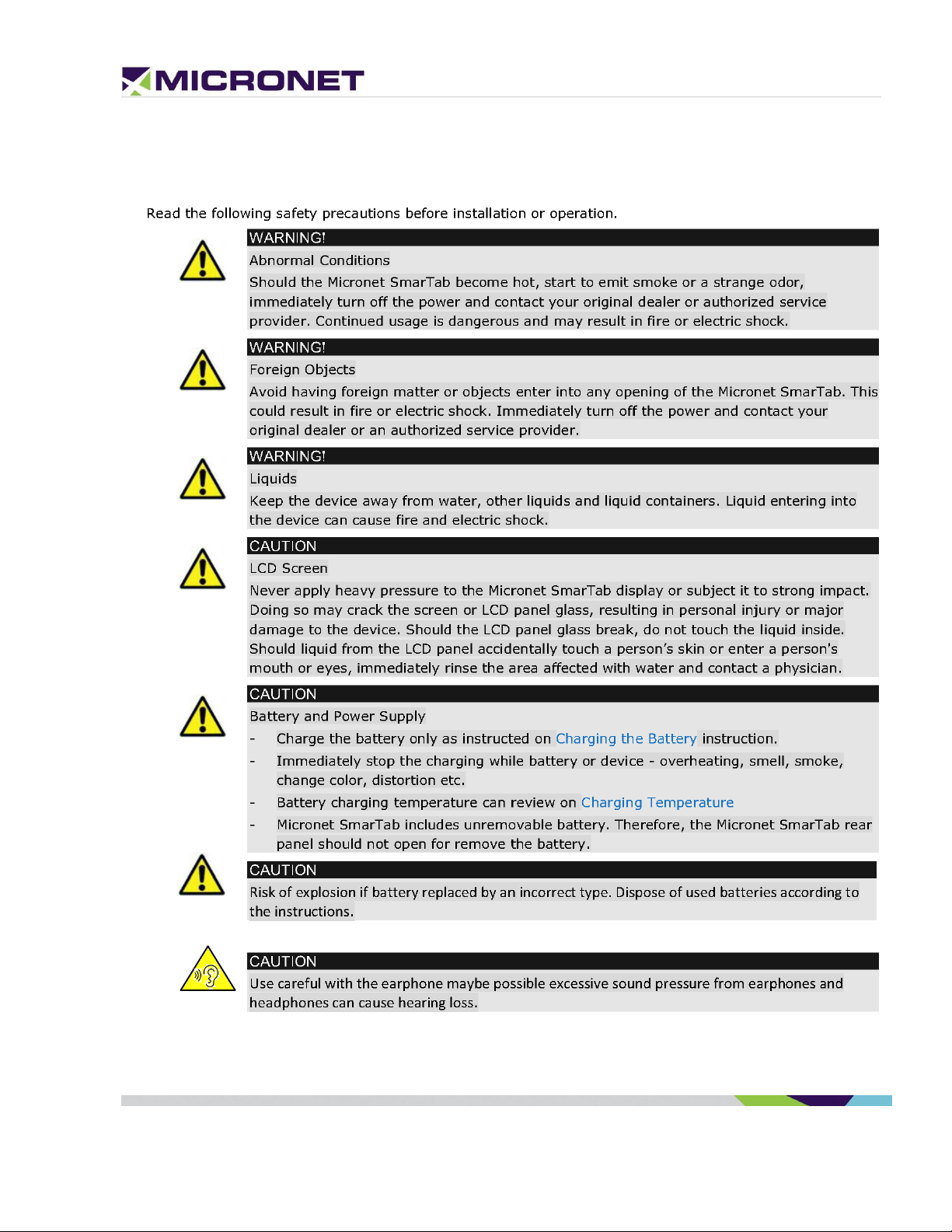
Safety Precautions
Rev. 1 Micronet SmartCAM™ - Hardware Guide 6 / 50
Page 7

1. Introduction
Micronet SmartCAM Platform Overview
In today’s commercial Telematics industry there is a growing demand for onboard devices that not only
send sensor data from the vehicle and driver environment for backend processing, but devices that also
analyze, detect, and notify the driver in real-time of any potential safety risks, operational errors, and
protocol violations. Events such as near-collision, tailgating, unsafe lane departures, hard
braking/cornering/accelerating, stop sign violations, speeding, distracted driving, driver fatigue, and
more comprise a rich dataset that is used by fleet managers to measure their drivers’ skills and
performance. It is also used to deploy training and education programs that result in improved fleet
safety, reduced insurance claims and premiums, higher up-time, and lower maintenance costs.
The Micronet SmartCAM™ enables fleet managers to address all these safety events not only through
conventional Telematic sensors such as GPS, 3D accelerometer, I/O, and CANbus, but also by providing
the ‘Full Picture’ through a rich set of real-time, onboard video analytics and AI capabilities enabled by a
dual automotive-grade camera for road and in-cabin monitoring all packaged into a single device. This
saves costly installations of separate ELD device installations for Telematics, ADAS, and DashCams. It
also saves upload data due to the local video analytics processing done on the device and its powerful
computing platform.
With the ability to run multiple applications simultaneously, the Micronet SmartCAM™ allows Telematics
Service Providers and System Integrators to extend their offering beyond their applications and provide
customers with advanced 3rd party mobility and video analytics applications.
In the Vehicle
Placed on the vehicle windshield, the Micronet SmartCAM™ functions as a high-end camera and onboard
Telematics computer. With integrated GPS, rear and front cameras, cellular communications, various
sensors, and support for a variety of vehicle-bus and peripheral interfaces, the Micronet SmartCAM™
enables a host of Fleet Management and Video Analytics solutions such as: ADAS, Driver Fatigue,
ELD/HOS, fleet tracking, driver behavior, real-time driver coaching and fuel management, remote
diagnostics, DVIR, backend communications, and much more.
The Micronet SmartCAM’s two cameras, together with its powerful processor and memory, allows it to
run advanced algorithms required for video analysis applications like tailgate monitoring, unsafe lane
departures, collision warnings, speed limit and stop sign detection, driver fatigue, distracted drivers,
driver ID, and passenger counting.
Rev. 1 Micronet SmartCAM™ - Hardware Guide 7 / 50
Page 8

Basic
Intermediate
Premium (V2)
CAN BUS
X
X
J1939/J1708
Cellular
X
3G/HSPA+/4G LTE
3G/HSPA+/4G LTE
USB interface
Debug / Download
Debug / Download
Hub (OTG)
Memory
RAM/Flash
2GB/16GB
2GB/16GB
2GB/16GB
With a rich set of wireless and wired interfaces – Wi-Fi hotspot, BT tethering and BLE, Bluetooth audio,
NFC, Wi-Fi Direct, multiple CAN channels (including open/customizable CAN libraries), and multiple I/Os
– the Micronet SmartCAM™ can function as an in-cabin hub to easily connect with other devices,
sensors, and accessories. Driver notification features such as system status LEDs, warning indicators,
internal speakers, and microphone are also provided for device control and driver alerting purposes.
The Micronet SmartCAM™ lets drivers remain safe, effective, and efficient with on-the-go connectivity –
anytime and anywhere – using cellular communication and Wi-Fi. Its durable design withstands shocks
and a range of temperatures, allowing drivers to operate freely in any environment. Installed on the
windshield, the Micronet SmartCAM™ has a perfect view of the road and the cabin.
The Micronet SmartCAM™ is a superior and cost-effective solution for Video Telematics.
Micronet SmartCAM Models
Micronet has implemented the SmartCAM™ platform in three product variants: The Basic Model, an
Intermediate Model, and Enhanced Model. These models include powerful computing, extended
memory, GPS, Wi-Fi, Bluetooth, NFC, and more. In addition, each model supports a set of additional
features:
• Basic Model – provides support for 2 cameras, a QC SDM450 chipset (2GB/16GB memory), and
additional storage for DVR recording. This model is described in more detail in the Basic Model.
• Intermediate Model – In addition to the Basic Model, the Intermediate Model provides 4G LTE.
• Enhanced Model - provides basic + enhanced key features set, described in Enhanced Model
list below.
The following Table 1 distinguishes each model for their specific components:
Table 1: Micronet SmartCAM™ Models
Rev. 1 Micronet SmartCAM™ - Hardware Guide 8 / 50
Page 9

Compatibility with Micronet SmartX Products
The Micronet SmartCAM™ is based on the same hardware and software platform as the Micronet
SmartHub, SmarTab, and Tab 8 – Micronet’s next-generation Android On-Board-Computer. Telematics
Service Providers who develop applications for Micronet’s SmartX series products can easily adjust and
run those apps on the Micronet SmartCAM™ for customers who also need that as part of their solution.
Shorter Development Cycles
Powered by an open Android platform, the Micronet SmartCAM™ platform offers a comprehensive
development environment for independent application programming and system integration. Because of
the vast ecosystem of Android development tools and software frameworks, and a flourishing
community of developers, working with Android devices has rapid development and integration cycles.
Lower Total Cost of Ownership
Designed to operate in harsh automotive field environments, the Micronet SmartCAM™ lowers the total
cost of ownership by withstanding shocks, vibrations, and extreme temperatures
GSD® Software Services
Micronet’s GSD™ (Guardian System Design) is a cloud-based Software as a Service (SaaS) platform for
managing mobile devices in the field.
GSD™ enables remote delta-based, over-the-air, firmware, and application updates allowing customers
to keep devices relevant anywhere, anytime. It features Mobile Device Management functionality,
Remote Control, and self-tests.
Administrators can proactively monitor and manage connected devices with a flexible web interface.
Introducing GSD® - Advanced software tools to manage and support mobile devices in the field.
Micronet’s new comprehensive software framework called GSD® - Guardian System Design - is a cloud-
based Software-as-a-Service platform that provides advanced software tools to manage and support
applications and system firmware upgrades on Micronet and third-party devices installed in the field.
The GSD® enables remote over-the-air access and control of Android-based mobile devices to conduct
individual or group diagnostics to support training activity.
GSD® a fully integrated software framework enabling new levels of control, support, and corporate
policy compliance.
GSD® is offered on the Micronet SmartCAM™ series of rugged, automotive-grade MDTs. It enables both
firmware and application software to be remotely managed, simplifies maintenance, troubleshooting,
Rev. 1 Micronet SmartCAM™ - Hardware Guide 9 / 50
Page 10

and remote training, which significantly reduces operational costs over the lifetime of the product and
substantially improves user experience and customer satisfaction.
GSD® features white-label cloud-based SaaS solutions offered as two key services:
1. Mobile Device Management and remote control.
2. Fail-safe firmware and application over-the-air updates (FOTA/OTA).
Development Tool Kit
Micronet's SmartCAM™ Development Package provides all the tools required for product evaluation,
application development, quick-start, and product testing. The Developers Package contains all essential
hardware and software components as described in the following sections:
Hardware
• Micronet SmartCAM™
• SmartCAM™ Basic, Intermediate, or Enhanced Model
• Wall power supply
• Main cable harness
• Mechanical and interface connection accessories
• Mounting accessories
Software
• Software Development Kit (SDK) provides a set of software tools and API documentation.
• Android demo samples for some device features, including the source code.
Documentation
• Micronet SmartCAM™ Hardware Guide
• Micronet SmartCAM™ Getting Started Guide
• Micronet SmartCAM™ OS Update Guide
• Micronet SmartCAM™ Remote Control and Display Guide
Platform Key Feature Specifications
The Micronet SmartCAM™ Tablet key feature specifications are documented in the "Micronet
SmartCAM™
Datasheet" document provided with the DTK documentation.
Rev. 1 Micronet SmartCAM™ - Hardware Guide 10 / 50
Page 11
2. Micronet SmartCAM Views
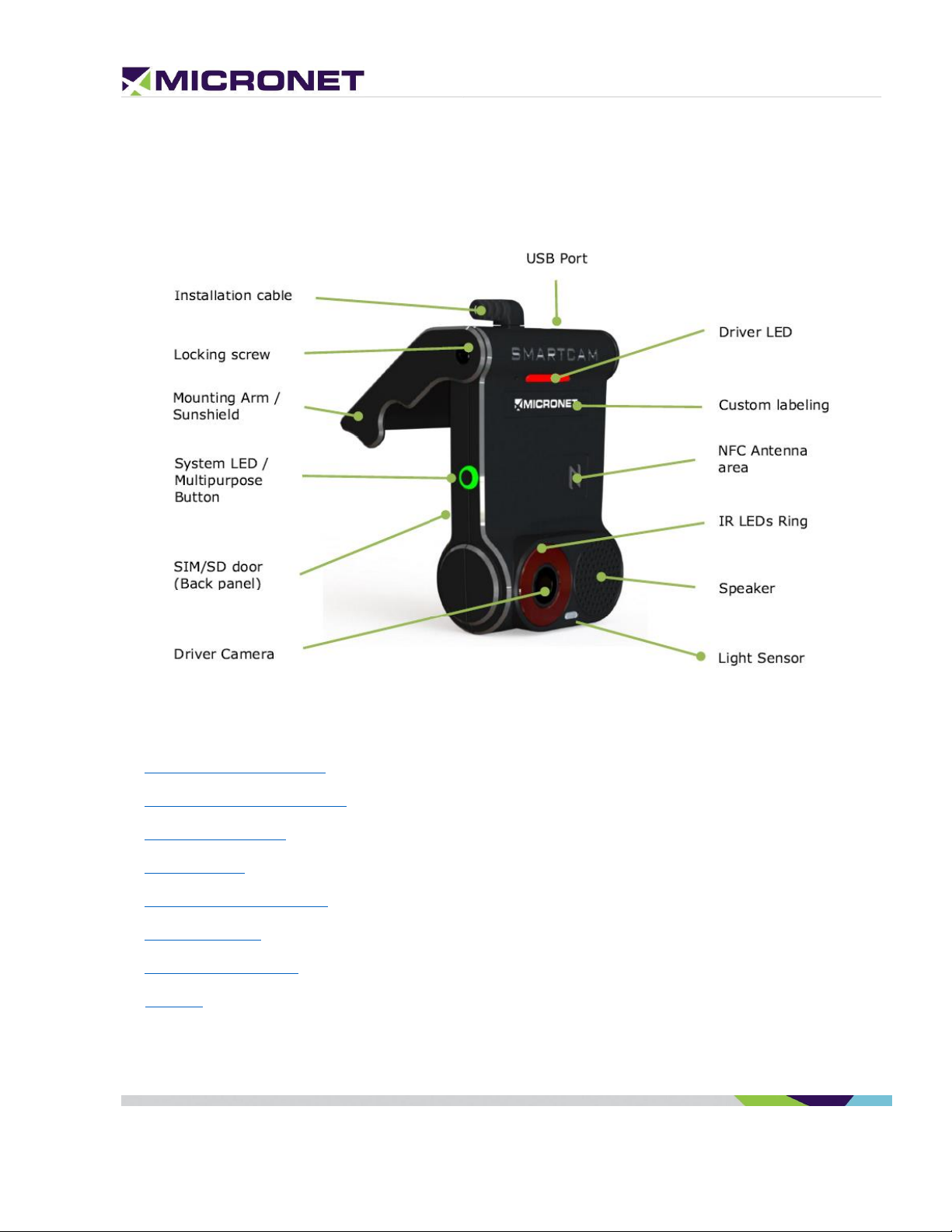
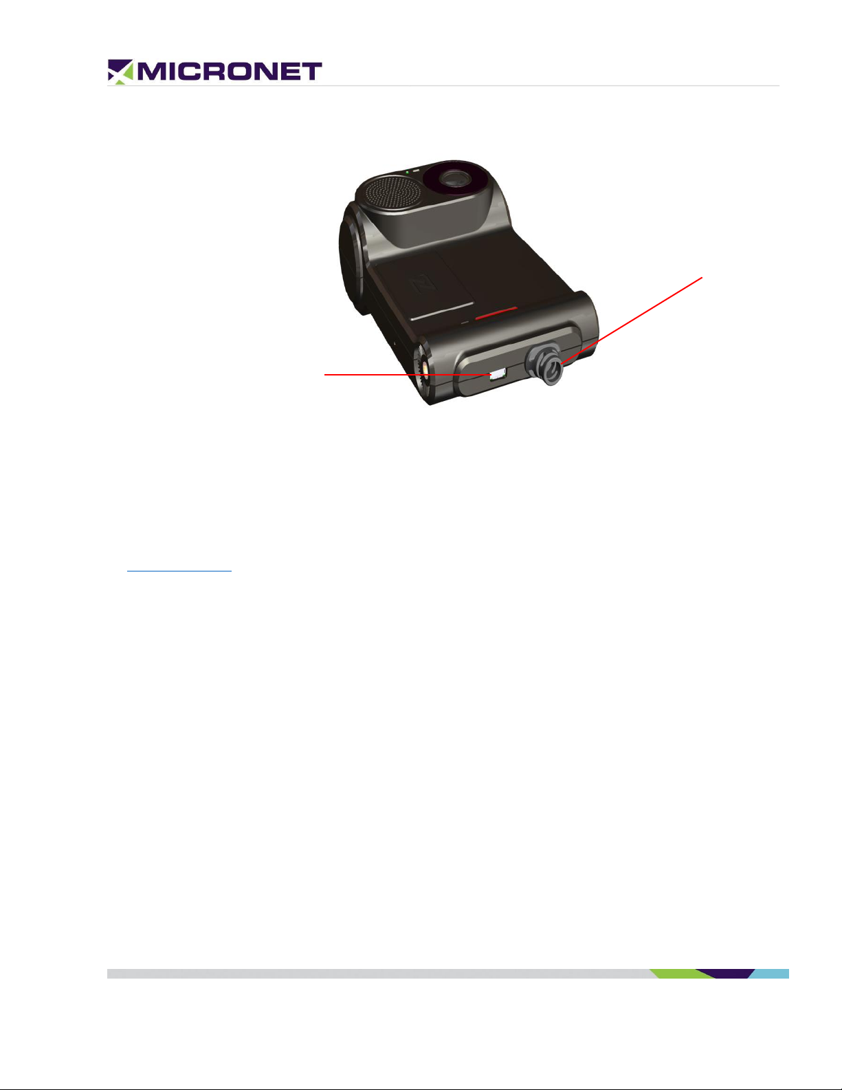
Micronet SmartCAM Front View
Figure 1: Micronet SmartCAM™ Front View
For more information about the Micronet SmartCAM™ front view see:
• Driver (In-Cabin) Camera
• System, Driver, and IR LEDs
• Multipurpose Button
• Locking Screw
• Mounting Arm / Sunshield
• Custom Labeling
• NFC Proximity Reader
• Speaker
Rev. 1 Micronet SmartCAM™ - Hardware Guide 11 / 50
Page 12
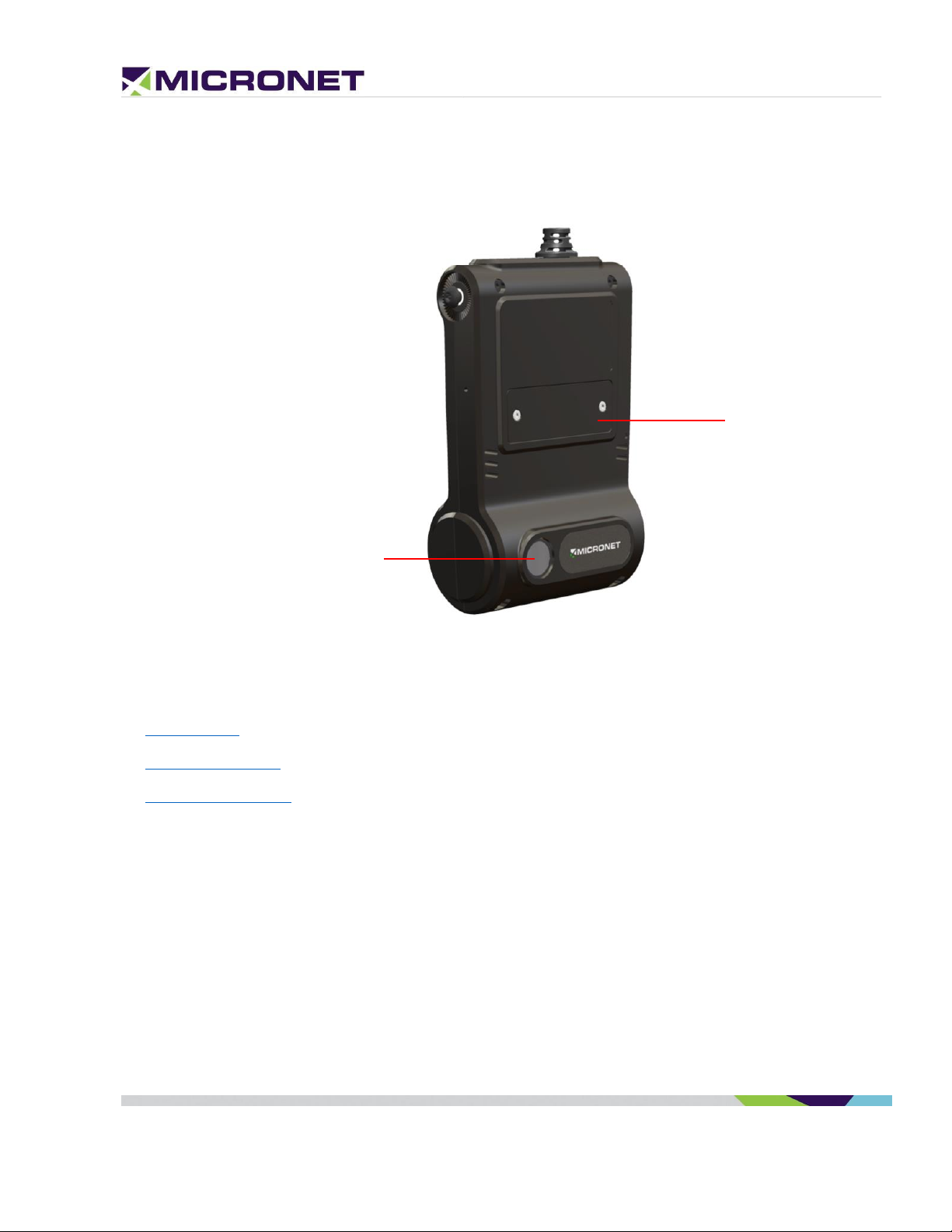
Road-Facing Camera
SD and SIM
Compartment
Micronet SmartCAM Rear View
Figure 2: Micronet SmartCAM™ Rear View
For more information about the Micronet SmartCAM™ rearview see:
• Memory Card
• MicroSIM Card Slot
• Road-Facing Camera
Rev. 1 Micronet SmartCAM™ - Hardware Guide 12 / 50
Page 13
USB Type-C Port
Installation Cable
Micronet SmartCAM Top View
Figure 2: Micronet SmartCAM™ Top View
For more information about the Micronet SmartCAM™ rearview see:
• Installation Cable
• USB Type-C Port
Rev. 1 Micronet SmartCAM™ - Hardware Guide 13 / 50
Page 14

3. Micronet SmartCAM Functional
Details
Platform Core
Operating System
The Micronet SmartCAM™ runs on Google™ AndroidTM 9.0 Pie.
Google and Android are trademarks of Google LLC.
ELD Compliance
The Micronet SmartCAM™ system boot time is ~40 seconds. The ELD requirement is up to 1 minute.
Please refer to the ELD Mandate for more information.
Application Development Environment
The Micronet SmartCAM™ supports any open source IDE. Micronet recommends using Android Studio.
Micronet’s Development Toolkit (DTK) includes the following components:
• Micronet SDK
• Application samples that demonstrate Micronet’s proprietary API
• Device management and upload tools
• Development accessories
• Documentation
For more details about the development infrastructure, product tools, and DTK contents, please refer to
the "Micronet SmartCAM™ Getting Started" Guide.
Processor
• Qualcomm Snapdragon
• High-performance Superscalar 8x ARM® Cortex™ A-53
TM
450 – 2 GHz Octa Core
RAM
2 GB LPDDR3 RAM memory
Flash Memory
16 GB eMMC
Rev. 1 Micronet SmartCAM™ - Hardware Guide 14 / 50
Page 15
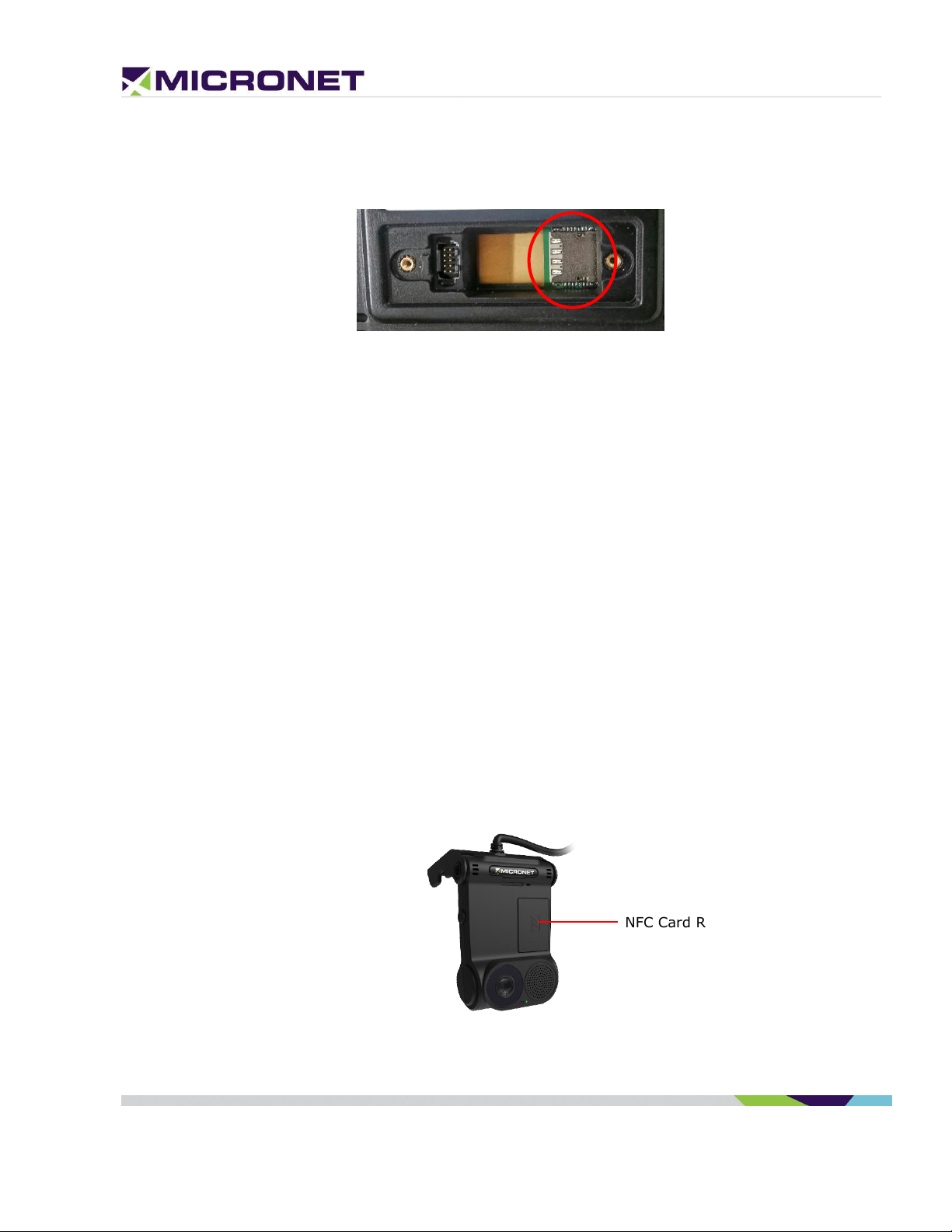
NFC Card Reader
Memory Card
The Micronet SmartCAM™ has a MicroSD card slot that supports cards formatted as ext4 and Fat32 up
to 128 GB. The MicroSD card slot is located on the road-facing panel behind the mountable sun-shield.
Watchdog
To monitor mission-critical processes, the platform provides an intelligent watchdog mechanism. The
watchdog provides various capabilities for temperature control and restarts if the system hangs. The
Android OS provides a software level watchdog mechanism by the "Application Manager" to control
application stability.
Figure 3: Micronet SmartCAM™ Memory Card Slot
User Interface
Hard Keys
The Micronet SmartCAM™ has one key on the side, which is configurable for a variety of purposes.
NFC Proximity
The Micronet SmartCAM™ provides an NXP PN547 NFC (Near Field Communication) proximity reader. When
the Micronet SmartCAM™ is docked in a cradle, the has an NFC slot for reading the NFC proximity card by
the Micronet SmartCAM™ tablet. It supports 13.56MHz cards and complies with IS15693 and IS18000-3
standards.
NFC Antenna
The NFC antenna is located on the Micronet SmartCAM™ in-cabin facing panel:
Figure 4: SmartCAM™ NFC Proximity Reader Area
Rev. 1 Micronet SmartCAM™ - Hardware Guide 15 / 50
Page 16

System, Driver, and IR LEDs
The Micronet SmartCAM™ has two LEDs, one tri-color system status LED (located on the left side), and
another driver feedback LED located at the top of the in-cabin facing panel. The Micronet SmartCAM™
also has a configurable Infrared (IR) LED ring which can be used for driver detection via heat sensing in
addition to the light-sensing LED for similar functionality.
Multipurpose Button
The Micronet SmartCAM™ has a multipurpose button that can be configured to power ON/OFF the
device or other customer functions.
Cameras
Road-Facing Camera
The Micronet SmartCAM™ has a 2 MP, Full HD (1080p) autofocus road-facing camera with autofocus,
which has low light sensitivity, 120 dB of dynamic range in HDR mode, 110° Field of Vision (FOV), and
runs at 30 frames per second (FPS).
Cabin-Facing Camera
The Micronet SmartCAM™ has a 2 MP, Full HD (1080p) autofocus cabin-facing camera with NearInfrared Sensitivity and IR LEDs, very wide dynamic range (for multiple exposures), a 140° FOV, and
run at 60 FPS.
Sound
Internal Speaker
The Micronet SmartCAM™ has a 1-Watt integrated speaker located on the in-cabin facing panel.
Microphone
The platform also has a highly sensitive microphone located at the bottom of the right panel.
Connectivity
Wireless LAN
The Micronet SmartCAM™ provides a dual-mode Wireless Local Area Network (IEEE 802.11 b/g/n/ac)
2.4 or 5 GHz module.
Wireless LAN communication is especially suited for high-speed data transfer over the air when a
hotspot infrastructure exists. For applications that require large data transactions, wireless LAN is the
most economical way to implement the solution.
Rev. 1 Micronet SmartCAM™ - Hardware Guide 16 / 50
Page 17

FDD LTE BANDS & FREQUENCIES
LTE BAND #
UPLINK (MHZ)
DOWNLINK (MHZ)
BANDWIDTH (MHZ)
DUPLEX SPACING (MHZ)
BAND GAP (MHZ)
1
1920 - 1980
2110 - 2170
60
190
130
2
1850 - 1910
1930 - 1990
60
80
20
3
1710 - 1785
1805 -1880
75
95
20
4
1710 - 1755
2110 - 2155
45
400
355
5
824 - 849
869 - 894
25
45
20
6
830 - 840
875 - 885
10
35
25
7
2500 - 2570
2620 - 2690
70
120
50
8
880 - 915
925 - 960
35
45
10
9
1749.9 - 1784.9
1844.9 - 1879.9
35
95
60
10
1710 - 1770
2110 - 2170
60
400
340
11
1427.9 - 1452.9
1475.9 - 1500.9
20
48
28
12
698 - 716
728 - 746
18
30
12
13
777 - 787
746 - 756
10
-31
41
14
788 - 798
758 - 768
10
-30
40
15
1900 - 1920
2600 - 2620
20
700
680
16
2010 - 2025
2585 - 2600
15
575
560
17
704 - 716
734 - 746
12
30
18
18
815 - 830
860 - 875
15
45
30
19
830 - 845
875 - 890
15
45
30
20
832 - 862
791 - 821
30
-41
71
21
1447.9 - 1462.9
1495.5 - 1510.9
15
48
33
22
3410 - 3500
3510 - 3600
90
100
10
23
2000 - 2020
2180 - 2200
20
180
160
24
1625.5 - 1660.5
1525 - 1559
34
-101.5
135.5
25
1850 - 1915
1930 - 1995
65
80
15
26
814 - 849
859 - 894
30 / 40
10
27
807 - 824
852 - 869
17
45
28
28
703 - 748
758 - 803
45
55
10
The WLAN module provides a 2.4 or 5 GHz IEEE 802.11 b/g/n/ac Ethernet adapter with a high rate of
wireless speed up to 150Mbps. The module supports WPA / WPA2 encryption, Wi-Fi Direct, and Hotspot
Tethering for up to 10 connected users simultaneously.
Bluetooth 4
The Micronet SmartCAM™ provides a Bluetooth 4.1 BLE module for voice and data.
Cellular Modem
The Micronet SmartCAM™ provides two hardware options of the cellular modem:
• 3.5G GSM - B8/850/900 and B3/1800/1900, WCDMA 1/2/4/5/8 (DC-HSPA+) B1/2100 and B8/900
for Europe.
• 4G LTE – North America bands, AT&T and T-Mobile B2 1900MHz, B4 AWS1700MHz, B5 850MHz,
B12/B13 700MHz. The modem supports all the following LTE FDD bands on Table 2 below: 1, 2, 3,
4, 5, 7, 8, 12, 13, 17, 20, 28.
Table 2: FDD LTE Bands & Frequencies
Rev. 1 Micronet SmartCAM™ - Hardware Guide 17 / 50
Page 18

MicroSIM Card Slot
The LTE/GSM modem requires a MicroSIM card connection. The MicroSIM card slot is located on the
road-facing panel behind the mountable sun-shield.
Cellular Antennas
The Micronet SmartCAM™ has two Main and Diversity internal integrated antennas.
GPS Receiver
The Micronet SmartCAM™ provides a highly sensitive GPS receiver which supports 50 different channels,
as well as NMEA0183 standard sentences, AGPS, GPS, and GLONASS satellites.
Figure 5: Micronet SmartCAM™ SIM Card Slot
GPS Antennas
The Micronet SmartCAM™ has an integrated Ceramic internal antenna.
Battery
Capacity
The Micronet SmartCAM™ includes a Non-removable Li-Polymer 160 – 350 mAh internal battery for
ordered shutdown upon loss of power from the vehicle’s battery.
Charging the Battery
The Micronet SmartCAM™ provides fast charging through its USB OTG connector on the left panel and
through the cradle, which is connected permanently to the vehicle’s battery. The also charges the
through the POGO pins at 5V DC power.
Charging Mechanism
The Micronet SmartCAM™ provides a smart charging mechanism. When connected to a power source
(e.g. wall mount power supply, PC USB, SmartCAM™ cradle), the battery is charged and also powers
the CPU in parallel. On reaching temperatures above 450C, the internal battery disconnects from the
Rev. 1 Micronet SmartCAM™ - Hardware Guide 18 / 50
Page 19

The operating system blocks charging when the temperature is over the defined
(45°C). By this function the device is protected even while in operation.
NOTE:
The product can connect only to a USB 3.0 or 2.0 interface (no superspeed).
power source. After disconnecting, the power source from the SmartCAM™ battery reconnects and
provides power to CPU. This mechanism prolongs the life of the battery.
Charging Temperature
The Micronet SmartCAM™ battery charging temperature is as follows:
• Battery operating temperature: 0°C to ~ +70°C, 45~85% RH
• Charge: 0°C to ~ +45°C, 45~85% RH
Motion Control
The Micronet SmartCAM™ provides an accelerometer, compass, and gyroscope module. The
accelerometer is an electromechanical device used to measure acceleration forces. Such forces may be
static like the continuous force of gravity or, as is the case with many mobile devices, dynamic to sense
movement or vibrations.
Communication Interfaces
Serial Communication
The Micronet SmartCAM™ provides serial communication ports with both the standard and enhanced
models. Each model includes a single serial port for communication and a serial debug port for
debugging.
Please refer to the detailed description of the Standard, Intermediate, and Enhanced Serial
Communication.
USB Communication
The Micronet SmartCAM™ supports a USB Type-C interface; it located on the Micronet SmartCAM™ Top
View of the device.
The SmartCAM™ standard supports USB Client interface for ADB communication. The enhanced support
two USB communication ports, one USB Host and one USB Client device. Please refer to the detailed
description of the standard USB Communication and of the enhanced USB Communication.
Rev. 1 Micronet SmartCAM™ - Hardware Guide 19 / 50
Page 20

General Purpose I/O
Input lines
The Micronet SmartCAM™ supports general-purpose input lines for ignition sense, automotive digital
lines, A2D, and other functions.
The standard model includes one input line for ignition sense. The enhanced model includes one input
line for ignition sense and seven general-purpose input lines. Please refer to the detailed description of
the standard Automotive Input and for the enhanced Analog and Digital Input lines.
Output Lines
The Micronet SmartCAM™ supports general-purpose Open-Collector output lines for various functions,
through the enhanced only. Please refer to the detailed description of the enhanced Open Collector
Output lines.
Vehicle Bus Connectivity
SAE J1939 CANBus
The Micronet SmartCAM™ provides two SAE J1939 CANBus ports through its enhanced model that
enables the connection of a variety of vehicle peripherals, such as the vehicle's computer, vehicle's
sensors, and so on. Please refer to the detailed description of the enhanced SAE J1939 CANBus.
Single Wire CANBus
The Micronet SmartCAM™ provides a single wire CANBus port through its enhanced model. Please refer
to the detailed description of the enhanced Single Wire CAN.
SAE J1708
The Micronet SmartCAM™ provides a J1708 port through its enhanced model. Please refer to the
detailed description of the enhanced SAE J1708. If you connect to the J1708 port, you can only connect
to one additional J1939 port.
Rev. 1 Micronet SmartCAM™ - Hardware Guide 20 / 50
Page 21

4. Micronet SmartCAM™ Models
Overview
The Micronet SmartCAM™ Platform offers various types of vehicle, allowing durable, protected Device
mounting and electronic connection in the vehicle. Compatible with a standard “RAM” mounting arm,
the supports easy installation and adjustable device position for convenience of use in an agitated
vehicle cabin environment.
There are three models of the Micronet SmartCAM™ available: the Intermediate Model and Enhanced
Model – each supporting various features and connection interfaces.
A Micronet SmartCAM™ Device "Lock" option is available on both Standard and Enhanced models to
support the "Fixed-Mounted" solution operation only, by preventing of the Device removal. For more
details, refer to Fix Mount Lock.
ELD Mandate
The ELD (Electronic Logging Device) Mandate in the USA requires electronic devices to be always
connected to the telematics vehicle. Since the Micronet SmartCAM™ is a portable device and all
telematics information is stored on the device, the is equipped with an LED and Buzzer to alert when
the device not docked while the vehicle’s ignition switch is ON. This LED and Buzzer WARN the driver
and reminds him or her to dock the device in the cradle.
Fix Mount Lock
The Micronet SmartCAM™ has a locking mechanism option to permanently install the device and
prevent tampering. It is an option when a fix mount installation is required. The fix mount lock parts
include one screw to prevent pushing the latch and an adhesive cover to hide the screw.
LED and Buzzer
The LED and buzzer are used to alert the driver that the Micronet SmartCAM™ is not locked in place.
This alert is enabled by default. The cradle’s MCU firmware provides an API to disable both the LED and
buzzer if required.
Rev. 3 Micronet SmartCAM™ - Hardware Guide 21 / 50
Page 22

5. Standard Model
Overview
The Standard (Basic) model of the SmartCAM™ includes a basic set of interfaces including power, ground,
ignition, serial communication as well as serial debug ports, and GPIOs.
Functional Details
The Micronet SmartCAM™ standard provides the following interfaces:
• 12V/24V line to charge the Micronet SmartCAM™ battery
• Digital input signal for ignition switch control
• A single automotive input and an open-collector output
• USB Type-C for ADB connection
• Serial communication and serial debug ports
z
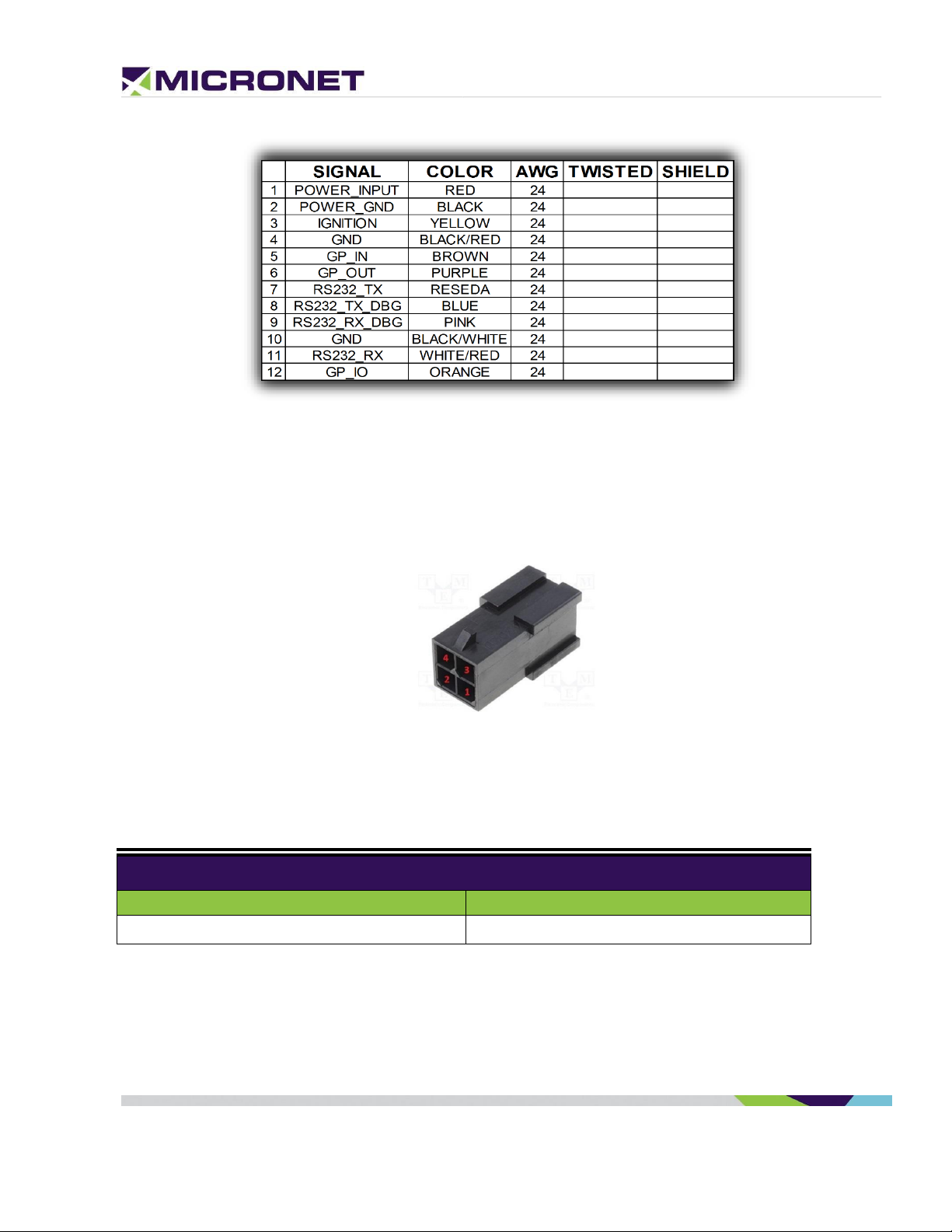
Standard Cradle Dev Cable
The Micronet SmarTab 8 standard cradle development cable, shown in figure 6 below, exposes power,
ignition, USB Type-C, a serial communication line and a serial debug line, and two GPIOs.
Figure 6: Micronet SmartCAM Standard & Intermediate Model Cable Harness GCAB516.
The pinout for P1, P2, and P3 is displayed in the standard cradle pinout in Figure 7 below:
Rev. 3 Micronet SmartCAM™ - Hardware Guide 22 / 50
Page 23

Micronet SmartCAM™ Standard Current Consumption
12V
24V
3mA
3mA
Figure 7: Micronet SmartCAM Standard & Intermediate Model Cable Pinout
Power Connector
The power connector (marked as P1) is a 4-pin, 2 row MicroFit 3.0 series Molex male connector and the
pinout for power and ignition lines are described in figure 8 below:
z
Figure 8: Molex 4-Pin Male Connector
Power Consumption
Table 3: Micronet SmartCAM™ Standard Current Consumption
Rev. 3 Micronet SmartCAM™ - Hardware Guide 23 / 50
Page 24

Serial Communication
The Ignition input line powers ON the Micronet SmartCAM™ from shutdown and
suspend states. For proper power management implementation, the ignition input line
should connect to the vehicle's ignition switch, and power to the should connect to the
vehicle's battery. See Electrical Installation for more information.
Note:
OS Burn using Fastboot only works through the Micronet SmartCAM™ USB Type-C
plug.
Serial Port 1 (COM1)
The Micronet SmartCAM™ Intermediate Model supports an (EIA) RS-232 level serial communication on its
port. It provides TX and RX signals at 300 to 115,200bps.
Debug Serial Port (COM7)
The Intermediate Model also supports an EIA-RS232 level serial communication port for Co-Processor
debugging purposes. The port supports a baud rate of 300 to 115,200bps, and provides the TX and RX
signals only.
USB Communication
USB TYPE-C
The standard cradle supports a USB Type-C port (not part of the external cable). It supports DFP
(Downstream Facing Port) for device connection as UFP (Upstream Facing Port) for connecting to a USB
HUB, Desktop, ADB for debugging, device configuration, and application development. It also supports
dual-role behavior according to USB3.x standard for DRP (Dual Role Port).
You can use the USB through the Micronet SmarTab 8 USB Type-C connector on the top of the device next
to the installation cable.
z
Automotive Input
The Micronet SmartCAM™ standard provides one automotive digital input for ignition.
Rev. 3 Micronet SmartCAM™ - Hardware Guide 24 / 50
Page 25

Table 4: Ignition line States, Electrical Parameters
Input State
Typical
Minimum
Maximum
Low
0V
-30V
+6V
High
12V-24V
+7V
+30V
General Purpose I/O
Analog and Digital Input lines
In addition to the ignition line, the SmartCAM™ provides one automotive input line (0-32V). This input lines
can be read as digital (state 0 or 1) or analog (voltage level) lines. It also provides a configurable GPIO for
input/output. For more information about these interface signals please see the digital output signals map
Pinout by Functionality.
Digital input
z
IGN (automotive voltage state) is for monitoring the ignition switch signal. The other input line can be used
for any purpose, like sensing door opening, sensing bus amber lights, etc.
Analog Input
GPIO can be treat as analog input to monitor the value range of compatible vehicle sensors, such as an
analog fuel gauge. The supported voltage range is from 0V to 30V.
Open Collector Output
The SmartCAM™ also provides one O.C output line for external peripheral control. For more information
about these interface signals please see the digital output signals map Pinout by Functionality.
Rev. 3 Micronet SmartCAM™ - Hardware Guide 25 / 50
Page 26

6. Intermediate Model
Overview
The Intermediate model of the SmartCAM™ has all of the same functionality and pinouts as the Standard
model; however, it also has 4G LTE cellular data enabled for backend server updates and statistics.
Functional Details
The Micronet SmartCAM™ intermediate model provides the following interfaces:
• 12V/24V line to charge the Micronet SmartCAM™ battery
• Digital input signal for ignition switch control
• An automotive input, and an open-collector output
• USB Type-C for ADB connection
• Serial communication port and serial debug port
Standard & Intermediate Model Dev Cable
The Micronet SmartCAM standard and Intermediate development cable, shown in figure 9 below,
exposes power, ignition, a serial communication line and a serial debug line, and two GPIOs:
z
Figure 9: Micronet SmartCAM Standard & Intermediate Model Cable Harness GCAB516.
The pinout for P1, P2, and P3 is displayed in the standard cradle pinout in Figure 10 below:
Rev. 3 Micronet SmartCAM™ - Hardware Guide 26 / 50
Page 27
Micronet SmartCAM™ Intermediate Current Consumption
12V
24V
~200mA
3mA
Figure 10: Micronet SmartCAM Standard & Intermediate Model Cable Pinout
Power Connector
The power connector (marked as P1) is a 4-pin, 2 row MicroFit 3.0 series Molex male connector and the
pinout for power and ignition lines are described in figure 11 below:
z
Figure 11: Molex 4-Pin Male Connector
Power Consumption
Table 5: Micronet SmartCAM™ Intermediate Current Consumption
Serial Communication
The intermediate model similarly supports a serial communication port for external device connection, and
a debug port connected to the MCU Co-Processor. These ports support various hardware and software flow
Rev. 3 Micronet SmartCAM™ - Hardware Guide 27 / 50
Page 28

control functions. For more information about the interface signals, please see the signal map Pinout by
Note:
OS Burn using Fastboot works through the Micronet SmartCAM™ USB Type-C plug.
Functionality.
Serial Port 1 (COM1)
The intermediate model supports an (EIA) RS-232 level serial communication on its port. It provides TX
and RX signals at 300 up to 115,200bps. The serial port provides one pair of communication control
handshake CTS/RTS signals.
Debug Serial Port (COM7)
The intermediate model supports EIA-RS232 level serial communication port for Co-Processor debugging
purposes. The port supports a baud rate of 300 to 115,200bps, and provides the TX and RX signals only.
USB Communication
USB TYPE-C
The intermediate model supports a USB Type-C port (not part of the external cable). It supports DFP
(Downstream Facing Port) for device connection as UFP (Upstream Facing Port) for connecting to a USB
HUB, Desktop, ADB for debugging, device configuration, and application development. It also supports
dual-role behavior according to USB3.x standard for DRP (Dual Role Port).
z
You can use the USB through the Micronet SmarTab 8 USB Type-C connector on the top of the device next
to the installation cable.
Automotive Input
The Micronet SmartCAM™ standard provides one automotive digital input for ignition.
Rev. 3 Micronet SmartCAM™ - Hardware Guide 28 / 50
Page 29

The Ignition input line powers ON the Micronet SmartCAM™ from shutdown and
suspend states. For proper power management implementation, the ignition input line
should connect to the vehicle's ignition switch, and power to the should connect to the
vehicle's battery. See Electrical Installation for more information.
Table 6: Ignition line States, Electrical Parameters
Input State
Typical
Minimum
Maximum
Low
0V
-30V
+6V
High
12V-24V
+7V
+30V
General Purpose I/O
Analog and Digital Input lines
In addition to the ignition line, the SmartCAM™ provides one automotive input line (0-32V). This input lines
can be read as digital (state 0 or 1) or analog (voltage level) lines. It also provides a configurable GPIO for
input/output. For more information about these interface signals please see the digital output signals map
Pinout by Functionality.
z
Digital input
IGN (automotive voltage state) is for monitoring the ignition switch signal. The other input line can be used
for any purpose, like sensing door opening, sensing bus amber lights, etc.
Analog Input
GPIO can be treat as analog input to monitor the value range of compatible vehicle sensors, such as an
analog fuel gauge. The supported voltage range is from 0V to 30V.
Open Collector Output
The SmartCAM™ also provides one O.C output line for external peripheral control. For more information
about these interface signals please see the digital output signals map Pinout by Functionality.
Rev. 3 Micronet SmartCAM™ - Hardware Guide 29 / 50
Page 30

7. Enhanced Model
Overview
The Enhanced Model of the Micronet SmartCAM™ similarly supports a serial communication and serial
debug port, control I/O signals, and in addition it offers vehicle BUS interface connections that a developer
can use to implement his or her ADAS and Telematics Solution.
Platform Core
MCU Processor
The enhanced MCU CPU consists of the Freescale K20_120 MQX RTOS.
Functional Details
The Micronet SmartCAM™ enhanced model provides the following interfaces:
z
• 12V/24V for charging the Micronet SmartCAM™ battery
• Digital input signal for ignition switch control
• One general-purpose input line, A2D, or Automotive digital input
• One general-purpose open-collector output line
• A serial communication port and a serial debug port
• Two J1939 CAN interfaces
• Single Wire CAN
• J1708 interface
Enhanced Model Dev Cable
In addition to the standard model, the Micronet SmartCAM enhanced model also provides two J1939 CAN
interfaces, a Single Wire CAN line, and a J1708 line. These added interfaces are shown below in figures 12
and 13 on the enhanced model development cable drawing and pinout:
NOTE: The Micronet SmartCAM DTK cable (P/N: GCAB618) includes MicroFit 3.0 Molex
connectors crimped to the ends of the wires, but the Standard, Intermediate, and Enhanced
model Production cables all come with open-ended wires.
Rev. 3 Micronet SmartCAM™ - Hardware Guide 30 / 50
Page 31

Figure 12: Micronet SmartCAM Enhanced Model Cable Drawing (P/N: GCAB618).
The pinouts for P2 – P6 are displayed in the enhanced cradle pinout in Figure 13 below:
z
Figure 13: Micronet SmartCAM Enhanced Model Cable Pinout
Vehicle Bus Connectivity
CANbus Connector
The CANbus connector (marked as P2) is a 10-pin, 2 row MicroFit 3.0 series Molex male connector, shown
in figure 14 below, which provides CAN 1 HIGH/LOW, CAN 2 HIGH/LOW, J1708, and Single Wire CAN:
Rev. 3 Micronet SmartCAM™ - Hardware Guide 31 / 50
Page 32

Figure 14: Molex 10-Pin Male Connector
SAE J1939 CANBus
The SmartCAM™ enhanced model provides two SAE J1939 CANBus ports that enable the connection of a
variety of vehicle peripherals, such as the vehicle's computer, vehicle's sensors and so on.
The provided CANBus V2.0B (a 1 Mbps port) supports the following functionality:
• 0 - 8-byte length in the data field
• Standard and extended data and remote frames
z
• Two receive buffers with prioritized message storage
• Six 29-bit filters
• Two 29-bit masks
• Three transmit buffers with prioritization and abort features
Single Wire CAN
The SmartCAM™ enhanced provides SAE J2411 single wire for CAN network applications with low
requirements regarding bit rate and bus length. The communication takes place via just one bus line with a
nominal data rate of 33,3 Kbit/s (83,3 Kbit/s in high-speed mode for diagnostics).
SAE J1708
The SmartCAM™ enhanced provides SAE J1708 port. The SAE J1708 is a standard used for serial
communications between ECUs on a heavy-duty vehicle and between a computer and the vehicle. With
respect to Open System Interconnection model (OSI), J1708 defines the physical layer. If connected to the
J1708 port only one other J1939 port will be available.
Serial Communication
The enhanced model similarly supports a serial communication ports for external device connections, and a
debug port connected to the MCU Co-Processor. These ports support various hardware and software flow
Rev. 3 Micronet SmartCAM™ - Hardware Guide 32 / 50
Page 33

control functions. For more information about the interface signals, please see the signal map Pinout by
Micronet SmartCAM™ Enhanced Current Consumption
12V
24V
5mA
4mA
Functionality.
Serial Port 1 (COM1)
The enhanced model supports an (EIA) RS-232 level serial communication on its port. It provides TX and
RX signals at 300 up to 115,200bps. The serial port provides one pair of communication control handshake
CTS/RTS signals.
Debug Serial Port (COM7)
The enhanced model supports EIA-RS232 level serial communication port for Co-Processor debugging
purposes. The port supports a baud rate of 300 to 115,200bps, and provides the TX and RX signals only.
Serial Connector
The Micronet SmartCAM enhanced model serial connector (P3) is a 6-pin, 2 row MicroFit 3.0 series Molex
male connector, and contains GPI1/GPO1, RS232_TX/RS232_RX, and RS232_TX_DBG/RS232_RX_DBG.
The serial communication connector is shown in figure 15 below:
z
Figure 15: Molex 6-Pin Male Connector
Power Consumption
Below in Table 7 is the current consumption of the Enhanced model of the Micronet SmartCAM:
Table 7: Micronet SmartCAM™ Enhanced Current Consumption
Rev. 3 Micronet SmartCAM™ - Hardware Guide 33 / 50
Page 34

USB Communication
Note:
OS Burn using Fastboot only works through the Micronet SmartCAM™ USB Type-C
plug.
The IGN line powers on the device from a shutdown state. For proper power
management, the input should be connected to the vehicle’s ignition switch.
USB HOST
The enhanced model is a USB HOST and Client. The USB Host interface supports the following profiles:
• USB Standard HID
• USB Printer (PCL)
• USB Storage USB CLIENT
The USB Client interface supports Android ADB for application development and device management.
The USB Client port provides Android’s ADB connectivity and supports:
• Device configuration
• Management tools
• Application development
• Debugging caution
Use the USB Client through the Micronet SmartCAM™ USB Type-C connector on the top of the device.
z
General Purpose I/O
Analog and Digital Input lines
The SmartCAM™ similarly provides one automotive input line (0-32V) through its enhanced model in
addition to the ignition line. The input line can be read as digital (state 0 or 1) or analog (voltage level)
lines.
Digital Input
IGN (automotive voltage state) is for monitoring the ignition switch signal. The other input line can be used
for any purpose, like sensing door opening, sensing bus amber lights, etc.
Rev. 3 Micronet SmartCAM™ - Hardware Guide 34 / 50
Page 35

Analog Inputs
GPIO can be treat as analog input to monitor the value range of compatible vehicle sensors, such as an
analog fuel gauge. The supported voltage range is from 0V to 30V.
Open Collector Output lines
The SmartCAM™ similarly provides one O.C output lines through its enhanced model for external peripheral
control. For more information about these interface signals please see the digital output signals map Pinout
by Functionality.
Customized Labeling
Micronet provides the option to attach a customized label based on your specifications. To enable
rebranding the product, Micronet will provide graphic files and size specifications. This is subject to an
additional charge per unit, based on the quantity ordered.
z
Figures 16, 17: Customized Front & Back Panel Labels
Rev. 3 Micronet SmartCAM™ - Hardware Guide 35 / 50
Page 36

8. Signals Map
Overview
This chapter describes the Micronet SmartCAM™ standard and enhanced signal interfaces.
Basic and Intermediate Signal Map
The Micronet SmartCAM™ Basic Model has the following interfaces on its main cable harness which are
soldered directly to the PCB:
• Power Line
• Ground Line
• Digital Input Line
• Open Collector Output
• USB Type-C connector cable to be connected on the computer USB Host connector
• Serial Port and Debug Port with TX, RX, GND signals, baud rate 300-115200bps
z
The following abbreviations are used:
• I - Input signal
• O - Output signal
• B - Bus signal
• V - Voltage signal
• G – Ground
• P – Positive
• N – Negative
Standard and Intermediate Model Signal Pinout
Pinout by Pin Number
The following table lists the 12 Basic and Intermediate Model signals by pin number:
Rev. 3 Micronet SmartCAM™ - Hardware Guide 36 / 50
Page 37

Table 8: Standard and Intermediate Model Signal Map (by Pin Number)
Pin
Signal
Type
Function
Specifications
1
POWER_INPUT
V
Input Power 12V/24V
Typical – 12V/24V
- Minimum continues – 6V (5V for up to
40ms according to ISO7637)
- Maximum continues – 32V
2
POWER_GND
G
Ground
3
Ignition Input
A
A2D Input
Ignition switch
Typical Min Max
Input Low: VIL 0V -30V 6V
Input High: VIH 12V-24V +8V +32V
4
GND G Ground
5
Automotive Input
I
Typical Min Max
Input Low: VIL 0V -30V 6V
Input High: VIH 12V-24V +8V +30V
0V-30V max, 12k OHM
6
O.C. Output
O
Open Collector Output
Max. switchable current = 300mA Max.
switchable voltage = +VIN
Max. saturation voltage = 0.6V
7
RS232_TX
O
Transmit Data (COM1)
EIA-RS232 Level
8
RS232_TX_DBG
O
Transmit Data DBG
MCU Debug port EIA-RS232 level
9
RS232_RX_DBG
I
Receive Data DBG
MCU Debug Port EIA-RS232 level
10
GND G Ground
11
RS232_RX
I
Receive Data (COM1)
EIA-RS232 Level
12
GP I/O
I/O
General-Purpose
Configurable General-Purpose Input / Output
z
Pinout by Functionality
The following table lists the 12 Basic and Intermediate Model signals by functionality:
Rev. 3 Micronet SmartCAM™ - Hardware Guide 37 / 50
Page 38

Table 9: Standard and Intermediate Model Signal Map (by functionality)
Pin
Signal
Type
Function
Specifications
1
POWER_INPUT
V
Input Power 12V/24V
Typical – 12V/24V
- Minimum continues – 6V (5V for up to
40ms according to ISO7637) Maximum
continues – 32V
-
2 POWER_GND
G
Ground
3
Ignition Input
A
A2D Input
Ignition switch
Typical Min Max
Input Low: VIL 0V -30V 6V
Input High: VIH 12V-24V +8V +32V
4
GND G Ground
5
Automotive Input
I
Typical Min Max
Input Low: VIL 0V -30V 6V
Input High: VIH 12V-24V +8V +30V
0V-30V max, 12k OHM
6
O.C. Output
O
Open Collector
Output
Max. switchable current = 300mA Max.
switchable voltage = +VIN
Max. saturation voltage = 0.6V
7
RS232_TX
O
Transmit Data
(COM1)
EIA-RS232 Level
8
RS232_TX_DBG
O
Transmit Data DBG
MCU Debug port EIA-RS232 level
9
RS232_RX_DBG
I
Receive Data DBG
MCU Debug Port EIA-RS232 level
10
GND G Ground
11
RS232_RX
I
Receive Data
(COM1)
EIA-RS232 Level
12
GP I/O
I/O
General-Purpose
Configurable General-Purpose Input / Output
z
Rev. 3 Micronet SmartCAM™ - Hardware Guide 38 / 50
Page 39

9. Enhanced Signals Map
Pin
Signal
Type
Function
Specifications
1
POWER_INPUT
V
Input Power 12V/24V
Typical – 12V/24V
- Minimum continues – 6V (5V for up to
40ms according to ISO7637)
Maximum continues – 32V
2 POWER_GND
G
Ground
3
Ignition Input
A
A2D Input
Ignition switch
Typical Min Max
Input Low: VIL 0V -30V 6V
Input High: VIH 12V-24V +8V
+32V
4
CAN 1 H
I/O
CAN 1 High Signal
Twisted Pair
5
CAN 1 L
I/O
CAN 1 Low Signal
Twisted Pair
6
J1708+ or CAN 2 H
I/O
J1708 Positive or CAN 2
High Signal
Twisted Pair
7
J1708- or CAN 2 L
I/O
J1708 Negative or CAN
2 Low Signal
Twisted Pair
8
O.C. Output
O
Open Collector Output 1
Max. switchable current = 300mA
Max. switchable voltage = +VIN
Max. saturation voltage = 0.6V
9
RS232_TX1
I
Transmit Data (COM1)
EIA-RS232 level
10
RS232_TX_DBG
O
Transmit Data DBG
MCU Debug port EIA-RS232 level
11
RS232_RX_DBG
I
Receive Data DBG
MCU Debug Port EIA-RS232 level
12
GND
G
Ground
13
RS232_RX1
I
Receive Data (COM1)
EIA-RS232 level
14
Automotive Input
I
Digital Input 1
Typical Min Max
Input Low: VIL 0V -30V 6V
Input High: VIH 12V-24V +8V +30V
0V-30V max, 12k OHM
Overview
The SmartCAM™ enhanced model has the following interfaces found on its main cable harness which is soldered
directly to the PCB:
Pinout by Pin Number
The following table lists the 16 enhanced model signals by pin number.
Table 10: Main Connector Signal Map (by pin number)
z
Rev. 3 Micronet SmartCAM™ - Hardware Guide 39 / 50
Page 40

Pin
Signal
Type
Function
Specifications
15
GPIO
I/O
General-Purpose
Configurable General-Purpose Input /
Output
16
SWC
I/O
Single Wire CAN
Pin
Signal
Type
Function
Specifications
1
POWER_INPUT
V
Input Power 12V/24V
Typical – 12V/24V
- Minimum continues – 6V (5V for up to
40ms according to ISO7637)
Maximum continues – 32V
2 POWER_GND
G
Ground
3
Ignition Input
A
A2D Input
Ignition switch
Typical Min Max
Input Low: VIL 0V -30V 6V
Input High: VIH 12V-24V +8V
+32V
4
CAN 1 H
I/O
CAN 1 High Signal
Twisted Pair
5
CAN 1 L
I/O
CAN 1 Low Signal
Twisted Pair
6
J1708+ or CAN 2 H
I/O
J1708 Positive or CAN 2
High Signal
Twisted Pair
7
J1708- or CAN 2 L
I/O
J1708 Negative or CAN
2 Low Signal
Twisted Pair
8
O.C. Output
O
Open Collector Output 1
Max. switchable current = 300mA
Max. switchable voltage = +VIN
Max. saturation voltage = 0.6V
9
RS232_TX1
I
Transmit Data (COM1)
EIA-RS232 level
10
RS232_TX_DBG
O
Transmit Data DBG
MCU Debug port EIA-RS232 level
11
RS232_RX_DBG
I
Receive Data DBG
MCU Debug Port EIA-RS232 level
12
GND
G
Ground
Pinout by Functionality
The following table lists the 16 enhanced model signals by functionality:
Table 11: Main Connector Signal Map (by functionality)
z
Rev. 3 Micronet SmartCAM™ - Hardware Guide 40 / 50
Page 41

z
Pin
Signal
Type
Function
Specifications
13
RS232_RX1
I
Receive Data (COM1)
EIA-RS232 level
14
Automotive Input
I
Digital Input 1
Typical Min Max
Input Low: VIL 0V -30V 6V
Input High: VIH 12V-24V +8V +30V
0V-30V max, 12k OHM
15
GPIO
I/O
General-Purpose
Configurable General-Purpose Input/Output
16
SWC
I/O
Single Wire CAN
NOTE:
In-vehicle installation instructions must be provided by a qualified installation technician.
10. SmartCAM™ Installation
Mechanical Installation
Mounting Sunshield
The mountable sunshield of the Micronet SmartCAM™ should be attached to the vehicle’s windshield
using the adhesive provided in the DTK for installation.
The fast and easy-to-use permanent bonding adhesive method provides high strength and long-term
durability. It is virtually invisible and keeps surfaces smooth. It can replace mechanical fasteners
(rivets, welds, screws) or liquid adhesives, eliminate drilling, grinding, refinishing, screwing, welding
and associated clean-up. It also creates a permanent seal against water, moisture and more.
Mounting Location and Dimensions
The sunshield can rotate every 8 degrees for click-turn positioning with two adhesive pads. Place the
adhesive pads on the mounting sunshield as shown in the figure below:
Rev. 3 Micronet SmartCAM™ - Hardware Guide 41 / 50
Page 42

Adhesive pads
Figure 18: Micronet SmartCAM™ Rear Panel Mounting Sunshield with Adhesive
Windshield Spacing
To mount the sunshield after applying the adhesive pads, press the sunshield firmly on to the vehicle
windshield about four inches above the wiper blade path slightly off-center to the right like below:
z
Figure 19: Micronet SmartCAM™ Single Windshield Mounting Spacing
Rev. 3 Micronet SmartCAM™ - Hardware Guide 42 / 50
Page 43
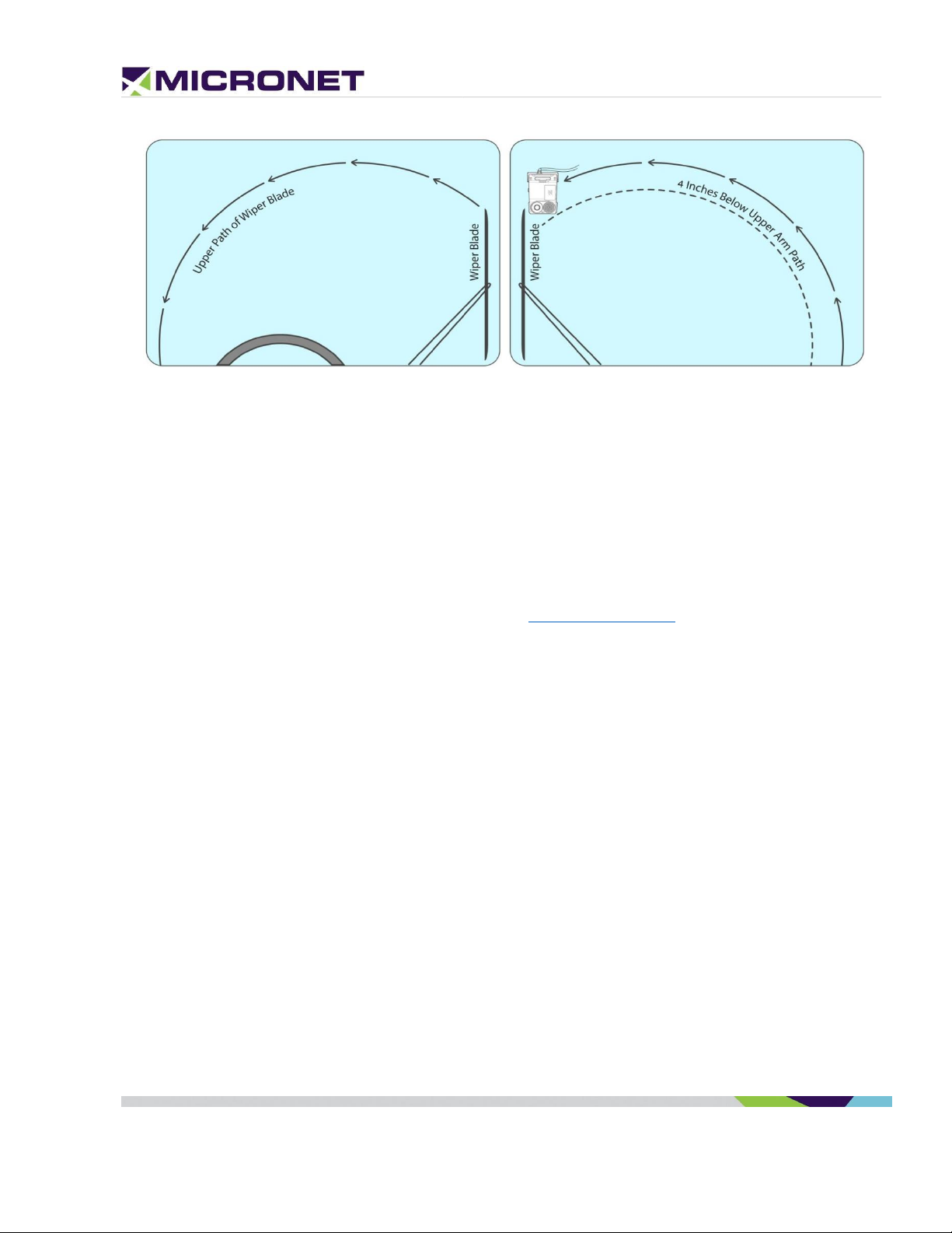
Figure 20: Micronet SmartCAM™ Double Windshield Mounting Spacing
Device Installation Steps
1. Determine the optimal positioning of the Micronet SmartCAM™ in the vehicle that provides easy
access and a clear view of both the road and the display.
2. Attach the two adhesive pads to the mounting sunshield of the Micronet SmartCAM™ (make sure
the sunshield is free of dust and debris.
3. Press and hold the mounting sunshield with adhesive pads on the pre-determined windshield
position for at least 30 seconds.
4. Follow the cable installation steps as described in Electrical Installation.
z
Electrical Installation
Vehicle Battery Connection
The Micronet SmartCAM™ input power connects directly to the vehicle’s battery. See the Electrical
Installation in Figure 21 below.
The supported nominal battery voltage supply is 12V or 24V DC, with an operating range between 8V to
30V DC.
Rev. 3 Micronet SmartCAM™ - Hardware Guide 43 / 50
Page 44
z
The must be connected to power before inserting the Micronet SmartCAM™ into the cradle. If
the Micronet SmartCAM™ is inserted while the is not connected to power, the Micronet
SmartCAM™ shuts down immediately.
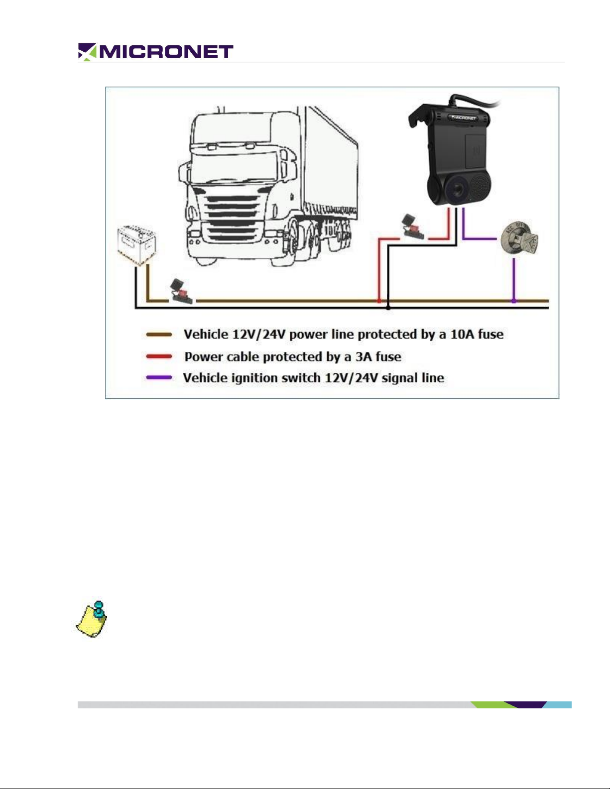
Figure 21: Electrical Installation Scheme
Electrical Installation Procedure
1. Prepare the wiring for power, ground and ignition switch in the vehicle, for connecting to the
Micronet SmartCAM™ cable.
2. The power signal connects to the vehicle's power line protected by a 10A fuse. Add an inline 3A
"Slow Blow" fuse with fuse holder for HHC/HHD blade-type fuses to the power cable.
3. The ground signal connects to the vehicle's ground line.
4. The ignition input signal connects to the vehicle's ignition switch line.
5. Fix the cable after verifying that all the functions are performing properly.
6. Arrange the cables using a plastic strip.
Rev. 3 Micronet SmartCAM™ - Hardware Guide 44 / 50
Page 45

11. Physical Characteristics
Dimension
Measurement
Micronet SmartCAM™ Dimensions & Weight
Width
6.50 inch
165 mm
Height
3.15 inch
80 mm
Depth
0.60 inch
15 mm
Weight
8.11 oz.
230 Gram
Table 12: Physical Characteristics
z
Rev. 3 Micronet SmartCAM™ - Hardware Guide 45 / 50
Page 46

12. Known Issues
Overview
The Micronet SmarTab 8 has some known issues discovered in the alpha launch and pre-production
testing. These are listed below:
Access Point Configuration:
NOTE: No cellular connections are vailable in the SmartCAM Basic model which requires the device to
connect via Wi-Fi. Active WiFi-Direct connections should NOT be available in specific cases i.e. no
application may use the device in WiFi-Direct or Hotspot mode when update is scheduled to allow
device connecting client AP in station mode.
BUG – Cellular Access Points (APs) are not pre-defined through a configuration files; neither are the
APs automatically generated upon booting the Micronet SmartCAM with microSIM cards.
WORKAROUND (temporary) – Customers should predefine AP data in the Micronet SmartCAM Wi-Fi
settings for internet connectivity.
z
SD Card Format Error:
BUG – When an SD Card is inserted to the SmartCAM, the Android OS attempts to format it as
"Internal" (application) storage, which fails and displays “Not Supported” (This is a specific version
limitation).
WORKAROUND (temporary) – To use the "External" (data storage) of the SD card, we recommend
formatting it externally on a PC as FAT32 file system prior to inserting the SD card it to the Micronet
SmartCAM device. Doing this will ensure correct behavior of the SD card as external storage.
Battery Depletion Reboot:
BUG – When the battery is depleted below a 5% threshold the Micronet SmartCAM will start booting in
a reboot loop after charging for some moments.
FIX IN PROGRESS – Should be fixed by using correct battery profile in firmware.
Battery Not Charging:
BUG – The Micronet SmartCAM’s battery won’t fully charge and it depletes too fast due to the absence
of customized battery profile.
FIX IN PROGRESS – Should be fixed by using correct battery profile in firmware.
Rev. 3 Micronet SmartCAM™ - Hardware Guide 46 / 50
Page 47

Roadside Camera Performace:
BUG – The Micronet SmartCAM’s roadside camera performance is degraded due to an uncalibrated
camera sensor.
FIX IN PROGRESS – Will be fixed by applying correct camera calibrations.
Microphone Gain:
BUG – The Micronet SmartCAM’s external microphone doesn’t provide sufficient gain.
FIX IN PROGRESS – The PCB will require a resistor of lesser value to provide the best possible gain.
IR LED Brightness:
BUG – The Micronet SmartCAM’s Infrared LED brightness of the driver side camera needs to be fine-
tuned for optimal performance.
FIX IN PROGRESS – Currently undergoing testing.
z
Rev. 3 Micronet SmartCAM™ - Hardware Guide 47 / 50
Page 48

Compliance Information
FCC Compliance:
FCC Compliance Statement: This device complies with Part 15 of the FCC Rules. Operation is
subject to the following two conditions: 1. This device may not cause harmful interference,
and 2. This device must accept any interference received, including interference that may
cause undesired operation. This device must accept any interference received, including
interference that may cause undesired operation. Product that is a radio transmitter is
labeled with FCC ID.
FCC Caution:
(1)Exposure to Radio Frequency Radiation. This equipment must be installed and operated in
accordance with provided instructions and the antenna(s) used for this transmitter must be
installed to provide a separation distance of at least 20 cm from all persons and must not be
collocated or operating in conjunction with any other antenna or transmitter. End-users and
installers must be provided with antenna installation instructions and transmitter operating
conditions for satisfying RF exposure compliance.
(2)Any changes or modifications not expressly approved by the grantee of this device could
void the user's authority to operate the equipment.
(3)This Transmitter must not be co-located or operating in conjunction with any other
antenna or transmitter.
(4)Changes or modifications to this unit not expressly approved by the party responsible for
compliance could void the user authority to operate the equipment.
(5) The modules FCC ID is not visible when installed in the host, or
(6) if the host is marketed so that end users do not have straight forward commonly used
methods for access to remove the module so that the FCC ID of the module is visible; then
an additional permanent label referring to the enclosed module: Contains Transmitter Module
FCC ID: U8O-A9 or Contains FCC ID: U8O-A9
z
Rev. 3 Micronet SmartCAM™ - Hardware Guide 48 / 50
Page 49

IC Canada Compliance:
Notes(IC)
(EN)This device complies with the applicable industry Canada) License exempt radio
apparatus, the operation is authorized under the conditions as follows: (1) this device may
not cause interference, and (2) the user of this device must accept any interference caused,
even if the interference is likely to affect its performance.
(FR)Le présent appareil est conforme aux CNR d'Industrie Canada applicables aux appareils
radio exempts de licence. L'exploitation est autorisée aux deux conditions suivantes : (1)
l'appareil ne doit pas produire de brouillage, et (2) l'utilisateur de l'appareil doit accepter tout
brouillage radioélectrique subi, même si le brouillage est susceptible d'en compromettre le
fonctionnement.
(EN)Radio frequency (RF) Exposure Information The radiated output power of the
Wireless Device is below the industry Canada(IC) radio frequency exposure limits. The
Wireless Device should be used in such a manner such that the potential for human contact
during normal operation is minimized. The device has also been evaluated and shown
compliant with the IC RF Exposure limits under mobile exposure conditions.(antennas at least
20cm from a person’s body)
(FR) informations sur l'exposition de radiofréquences (rf) la puissance de
rayonnement de l'appareil sans fil est inférieure à la fréquence radio d'industrie canada (ic)
limites d'exposition.l'appareil sans fil devrait être utilisé de façon telle que le potentiel de
contact pendant le fonctionnement normal est réduit au minimum. le dispositif a été
évalué et qui semble conforme à l'ic des limites d'exposition aux rf sous des conditions
d'exposition mobile. (antennes d'au moins 20 cm du corps d'une personne)
(EN)The following statement must be included with all versions of this document supplied to
an
OEM or integrator, but should not be distributed to the end user. This device is intended for
OEM integrators only.
Please See the full Grant of Equipment document for other restrictions
(FR) l'énoncé suivant la déclaration suivante doit être incluse dans toutes les versions de ce
document fourni à un oem ou intégrateur, mais ne devrait pas être distribuées à
l'utilisateur final. ce dispositif est destiné aux intégrateurs de oem. voir le document de
subvention d'équipement d'autres restrictions
(EN) The Innovation, Science and Economic Development Canada certification label of a
module shall be clearly visible at all times when installed in the host product; otherwise, the
host product must be labelled to display the Innovation, Science and Economic Development
Canada certification number for the module, preceded by the word "Contains" or similar
wording expressing the same meaning, as follows: Contains IC: 12186A-A9
where 12186A-A9 is the module's certification number
(FR)L'étiquette de certification d'un module d'Innovation, Sciences et Développement
économique Canada doit être clairement visible en tout temps, une fois installée dans le
produit hôte. sinon, le produit hôte doit porter une étiquette indiquant le numéro de
certification d'Innovation, Sciences et Développement économique Canada du module,
précédé du mot "contient" ou d'un libellé similaire exprimant le même sens, comme suit:
Contient IC: 12186A-A9 où 12186A-A9 est le numéro de certification du module
z
Rev. 3 Micronet SmartCAM™ - Hardware Guide 49 / 50
Page 50

EU Regulatory Conformance:
WLAN
Frequency(MHz):
2400-2462,
5150-5250;
5725-5850
Max Power
19 dBm
14 dBm
14 dBm
BT
Frequency(MHz):2402-2480
Max Power
8 dBm
The manufacturer hereby declares that this device is in compliance with the essential
requirements and other relevant provisions of Radio Equipment Directive 2014/53/EU.
The device is restricted to indoor use only when operating in the 5150 to 5350 MHz frequency
range.
z
Rev. 3 Micronet SmartCAM™ - Hardware Guide 50 / 50
 Loading...