

Page 1

Copyright Notice
TransPort NX User’s Guide
1
TransPort NX User’s
Guide
Copyright Notice
The information in this document is subject to change without prior notice in order
to improve reliability, design and function and does not represent a commitment
on the part of the manufacturer. In no event will the manufacturer be liable for
direct, indirect, special, incidental, or consequential damages arising out of the
use or inability to use the product or documentation, even if advised of the
possibility of such damages.
This document contains proprietary information that is protected by copyright. All
rights are reserved. No part of this document may be photocopied, reproduced, or
translated to another language without the prior written consent of:
Micron Electronics, Inc.
900 E. Karcher Road
Nampa, Idaho 83687
Phoenix is a trademark of Phoenix Technologies Ltd. CardSoft is a trademark of
SystemSoft Corporation. AutoCAD and Autoshade are trademarks of Autodesk,
Inc. IBM, OS/2, and VGA are trademarks of International Business Machines
Corp. Lotus, 1-2-3, and Symphony are trademarks of Lotus Development Corp.
Windows, Word, MS-DOS, and Microsoft are trademarks of Microsoft Corp. VESA
is a trademark of Video Electronics Standards Association.
MS-DOS, Windows 3.1, 95/98 and NT are trademarks of Microsoft Corp. Pentium
II and MMX are trademarks of Intel Semiconductor.
Other product names mentioned herein are used for identification purposes only
and may be trademarks and/or registered trademarks of their respective
companies.
While reasonable efforts have been made to ensure the accuracy of this manual,
the manufacturer and distributor assume no liability resulting from errors or
omissions in this manual, or from the use of the information contained herein.
P/N MAS001579-02, TransPort NX,
MJB 9-29-1999
(C)Copyright 1999. All Rights Reserved. Manual edition October, 1999.
Document Number MP989
Page 2

From the Editors...
TransPort NX User’s Guide
2
From the Editors...
This may be your first time setting up a computer, in which case, we hope that this
manual will be an effective resource for you and make this as much of a learning
process, and not a hassle.
There exists the possibility that you have already set up your machine, and you’ve
taken the manual out for a detailed look at your system’s features. You may want
to know about possible configuration changes and modifications that can be
made, or simply match wits with the glossary and see if you can come up with the
correct definition for BIOS without peeking.
Another reality is one of frustration, hair-pulling and the like. Many folks only open
the manual when “something isn’t working right.” Reconfiguring the CMOS
screens may have seemed like a good idea at the time, but now you are only
getting cranky beeps. Now what?! You may be trying to get help on-line but a
blank screen isn’t going to help you out much there, and you’ve pulled the user’s
guide out as a last resort.
Fair enough.
If the reason you got the user’s guide out is based on the last possibility... first
things, first... take a deep breath.
The system user’s guide is designed to help you in all of the above situations, and
give you a ready reference to the capabilities of your system.
A troubleshooting section may save you a call to technical support, should you be
staring at a blank screen right now.
We want to make this guide as useful as possible and welcome your comments.
Please provide the page and the manual part number (MAS001579-02) when you
send comments to: [email protected].
Whatever reason brought you to reading the user’s guide, Welcome!!! We hope it
makes your experience with Mi cron even better.
Page 3

Getting Started
About This Manual
3
About This Manual
Whether you are a new or experienced computer user, you will benefit more from
this manual if you are familiar with its organization.
Getting Started
Chapter One:
This section lists the special features of your TransPort NX
computer and available options. It also includes a description of the parts you
should have received and gives you step-by-step procedures for setting up and
starting the computer
System Features
Chapter Two:
This section outlines the layout and functionality of your TransPort
NX.
Running BIOS Setup
Chapter Three:
This section describes how to operate the Setup Utility that is
provided in the computer’s ROM BIOS. Several options are available in BIOS,
such as the ability to protect and supervise your notebook with password
protection.
Data Storage
Chapter Four:
This section explains the powerful ability of your TransPort NX to
utilize the Hard Disk drive, Removable Disk drive and CD-ROM.
Power Management
Chapter Five:
This section provides information on how to keep your TransPort
NX supplied with power.
Optional Accessories
Chapter Six:
This section provides an overview of devices that may be used with
the TransPort NX, such as an external monitor and keyboard. It also provides an
overview to the port replicator, which can turn your notebook into a functional
desktop computer.
Software Utilities
Chapter Seven:
This section explains the MRestore CD, which includes Drive
Image, Partition Magic and Drive Copy--three very powerful software tools--plus
the ZVHDD (save-to-disk) utility.
Troubleshooting
Chapter Eight:
This section provides a simple guide to common troubleshooting
techniques.
Page 4

Appendices
About This Manual
4
Appendices
Appendix A:
Specifications
Appendix B:
Regulatory Informati o n
Appendix C:
Safety Guidelines
Appendix D:
Fax/Modem Information
Appendix E:
Alternative Device Drivers
Appendix F:
Caring for Diskettes and CDs
Appendix G:
Abbreviations
Appendix H:
Glossary
Index
A comprehensive index is provided. You can look up areas of interest or need
without searching through the Table of Contents.
Peripheral Manuals
In addition to this manual, you will also want to consult the manuals for your
operating system and application software.
Manual Conventions
The following conventions are used throughout this manual:
N
OTE
:
Notes contain important information that is set off from the text.
W
ARNING
:
Caution messages appear before procedures which, if not observed, could
result in loss of data or damage to equipment. Failure to heed these warning
could negate the user warranty.
C
AUTION
:
Warning messages appear before procedures which, if not observed, will
result in loss of data or damage to equipment, and/or could result in
physical harm. Failure to heed these warning could negate the user
warranty.
Page 5

Table of Contents
5
Table of Contents
TransPort NX User’s Guide............................... 1
Copyright Notice .................................................................. 1
From the Editors... ............................................................... 2
About This Manual..................................... .... .... 3
Getting Started..................................................................... 3
Appendices ........................ ....... ...... ....... ...... ....... ................. 4
Index .................................................................................... 4
Peripheral Manuals .............................................................. 4
Manual Conventions ............................................................ 4
Chapter One - Getting Started......................... 11
Unpacking the TransPort NX ............................................. 11
Personal Inventory.............................................. ............... 12
Operating Environment ............................................. ....... .. 13
Heat, Cold, Humidity, and Glare.................................. 13
Work Location.............................................................. 14
Connecting to a Power Source .......................................... 14
Connecting the AC Adapter......................................... 14
Surge Suppressors...................................................... 15
Turning on the TransPort NX ............................................. 15
Ergonomics........................................................................ 17
Chapter Two - System Features...................... 19
Opening the TransPort NX................................................. 19
Left View ............................................................................ 20
DC-Jack....................................................................... 20
Fan .............................................................................. 20
PCMCIA Slots Compartments ..................................... 20
Main Battery ................................................................ 20
Fax/Modem (Optional)........................... ....... ...... ....... .. 20
Right View.......................................................................... 21
Microphone Jack ......................................................... 21
Line In.......................................................................... 21
Line Out....................................................................... 21
CD Bay......................................................................... 21
FDD Bay ...................................................................... 21
IrDA.............................................................................. 21
Rear View........................................................................... 22
Foot.............................................................................. 22
SVGA........................................................................... 22
Port Replicator Bay...................................................... 22
USB Ports.................................................................... 22
Parallel Port ................................................................. 22
Game/MIDI Port........................................................... 22
Serial Port .................................................................... 23
PS/2 Port................................... ...... ....... ...... ................ 23
TV OUT / In Ports ........................................................ 23
Bottom View ....................................................................... 23
CD-ROM Release Latch .............................................. 24
FDD BAY Release Latch ............................................. 24
Name Card Holder....................................................... 24
CPU Cover................................................................... 24
Main Battery Release Latch...................................... ... 24
Interior Features................................................................. 24
LCD.............................................................................. 25
Power Button ............................................................... 25
Power ON .................................................................... 25
Power OFF................................................................... 25
Power LED................................................................... 25
Indicator Display .......................................................... 25
Stereo Speakers .......................................................... 26
Touchpad..................................................................... 26
LCD Cover Switch........................................................ 27
Mouse Buttons............................................................. 27
Microphone.................................................................. 27
System Features ................................................................ 27
Central Processing Unit (CPU) .................................... 27
CPU Upgrade............................................................... 27
L2 Cache................................... ...... ....... ...... ...... ....... ... 28
Upgradeable System Memory ..................................... 28
VGA Graphics Accelerator........................................... 29
Removable Hard Disk Drive Module............................ 29
Page 6

Table of Contents
6
Removable CD-ROM................................................... 29
Audio System............................................................... 29
Audio Ports .................................................................. 29
Battery and AC Power System .................................... 29
Security........................................................................ 29
Input/Output Devices ................................................... 30
Other Devices .............................................................. 30
LCD Display.... ....... ...... ................................................ 30
LCD Care............................................................ ...... ... 30
External CRT Display................................................... 30
TransPort NX Keyboard ..................................................... 31
Description of Function Keys ....................................... 31
Windows 95 Keys ........................................................ 32
Hot Key Controls.......................................................... 33
Function Keys .............................................................. 33
Cursor Keys ................................................................. 33
Embedded Numeric Keypad ........................................ 34
System Status Window ................................................ 34
Touch Pad........................................................................... 34
Using the Touch Pad ................................................... 35
Touch Pad Precautions................................................ 36
Installing a Touch Pad Driver....................................... 36
Using the Stick Pointer................................................. 36
IR Communication.............................................................. 37
PCMCIA Cards and Expansion Sockets ............................ 38
Using PCMCIA Cards .................................................. 38
Inserting a PCMCIA Card ............................................ 39
Preparing the TransPort NX for Transport.......................... 39
Traveling with the TransPort NX .................................. 40
Power-on Self Test............................................................. 40
Operating System......................................... ...... ....... ......... 41
Resetting the System ......................................................... 41
Chapter Three - Running BIOS Setup............ 43
About BIOS Setup .............................................................. 43
Navigating Through BIOS Setup.................................. 43
Using Setup ................................................................. 44
Legend Bar .................................................................. 44
Accessing the BIOS Setup Program ........................ ... 44
In Case of Problems.................................................... 45
Save Changes and Exit Setup Program...................... 45
Main Menu.......................................................... ...... ...... ... 45
Standard CMOS Setup ...................................................... 46
Date............................................................................. 46
Time ............................................................................ 46
Primary Master............................................................ 46
Secondary Master ....................................................... 46
Secondary Slave ......................................................... 46
Drive Type A................................................................ 46
LCD & CRT ................................................................. 47
Halt On ........................................................................ 47
Memory ....................................................................... 47
BIOS Features Setup .................................................. 47
Quick Power On Self Test........................................... 47
Boot Sequence............................................................ 48
Boot Up NumLock Status ............................................ 48
Security Option............................................................ 48
Integrated Peripherals........................................................ 48
OnChip Primary PCI IDE............................................. 49
OnChip Secondary PCI IDE........................................ 49
Onboard FDC Controller ............................................. 49
Onboard Serial Port 1.................................................. 49
Onboard Serial Port 2.................................................. 49
Onboard Serial Port 2 Mode........................................ 49
FIR Mode Use DMA .................................................... 49
Onboard Parallel Port.................................................. 49
Parallel Port Mode....................................................... 49
ECP Mode Use DMA................................................... 49
Reset Data Configuration............................................ 49
Power Menu....................................................................... 50
Power On By Ring....................................................... 50
Battery Low ................................................................. 50
Battery Llow................................................................. 50
Resume on Schedule.................................................. 50
Save & Exit Setup .............................................. ...... ... 51
Exit Without Save........................................................ 51
Page 7

Table of Contents
7
Chapter Four - Data Storage ........................... 53
Data Storage and Retrieval................................................ 53
Floppy Disk Drive ........................................................ 53
CD-ROM...................................................................... 56
Removing the CD-ROM Drive ..................................... 57
Installing the CD-ROM Drive ..................................... .. 58
Multimedia Sound System............... ...... ...................... 59
Chapter Five - Power Management................. 61
Powering Your Notebook Computer................................... 61
Power Saving Modes ......................................................... 61
Full On Mode............................................................... 61
System Idle Mode........................................................ 61
Standby Mode . ...... ...... ....... ...... ....... ...... ....... ............... 62
Suspend To RAM ........................................................ 62
Suspend To Disk ......................................................... 63
A Suspend Example.................................................... 64
Hard Drive Spin Down................................................. 64
Batteries............................................................................. 64
Battery Discharge........................................................ 65
Recharging the Battery Pack....................................... 65
Battery Power System................................................. 67
Preparing the Battery Pack for Use ............................. 67
Battery Status.............................................................. 67
Battery Low Warning ................................................... 69
Small Battery for Real Time Clock............................... 69
Power Management Habits ......................................... 69
AC Adapter ..... ....... ................................................... ....... .. 69
Conserve Battery with AC Adapter.............................. 70
Screen Brightness.............................................................. 70
APM Interface .................................................................... 70
Chapter Six - Optional Accessories............... 71
External Devices................................................................ 71
External Keyboard....................................................... 71
External Mouse............................................................ 72
External Monitor .......................................................... 72
External Printer............................................................ 73
Serial Devices.................................................................... 73
Audio Sources and Output Devices ................................... 74
Universal Serial Bus........................................................... 74
LS-120 Drive ......... ...... ....... ...... ....... ...... ....... ...... ................ 74
Zip Drive............................................................................. 75
Optional Fax/Modem.......................................................... 75
Optional Port Replicator ..................................................... 76
Features....................................................................... 77
Connecting The Port Replicator................................... 78
Cold Dock .................................................................... 78
Disconnecting the Port Replicator................................ 79
DVD Installation.................................................................. 80
Chapter Seven - Software Utilities ................. 81
MRestore CD-ROM............................................................ 81
MCRC (Micron Customer Resource Center)...................... 81
PartitionMagic..................................................................... 81
Drive Image 3.0.................................................................. 82
Drive Image Professional............................................. 83
Drive Image System Requirements ............................. 83
Creating Image Files.................................................... 83
Advanced Options........................................................ 88
Disable SmartSector Copying...................................... 89
Verify Disk Writes......................................................... 89
ImageShield................................................................. 89
Split Image File Into Multiple Files............................... 89
Restoring Image Files.................................................. 89
Resize Options.......................... ...... ....... ...... ...... ....... ... 95
Advanced Options........................................................ 96
Check for File System Errors....................................... 96
Skip Bad Sector Check................................................ 96
Verify Check Writes ..................................................... 96
PartitionMagic..................................................................... 96
Partition Information..................................... ...... ....... ... 97
Partition Map ... ................................................... ....... ... 97
Partition List ........................................... ...... ...... ....... ... 98
PartitionMagic Help...................................................... 98
ReadMe File................................................................. 99
Page 8

Table of Contents
8
Completing Tasks Manually......................................... 99
Selecting a Hard Disk .................................................. 99
Selecting a Partition ..................................................... 99
Applying Changes to Your System ............................ 100
Changing PartitionMagic Preferences ....................... 100
Ignore OS/2 EA Errors on FAT .................................. 101
Skip Bad Sector Checks ............................................ 101
Set as Read-Only for PartitionMagic.......................... 102
Creating Partitions ..................................................... 102
Creating Bootable Partitions ...................................... 103
To Create a Partition.................................................. 104
Scenarios................................................................... 106
Deleting Partitions...................................................... 107
Changing Partition Labels.......................................... 108
Formatting Partitions.................................................. 108
Converting FAT to FAT32.......................................... 109
Converting FAT to NTFS ........................................... 110
Drive Copy ................................................................. 111
Copying Entire Drives ................................................ 112
Zero-Volt Data-Suspend Utility (ZVHDD) ......................... 113
Installation.................................................................. 114
Creating a Storage Partition on the Hard Drive ......... 114
Saving Session Data.................................................. 115
Program Functions..................................................... 117
Reformatting the Storage Partition............................. 117
Deleting the Storage File or Partition......................... 117
Routine Maintenance........................................................ 118
Windows Task Scheduler (Maintenance Wizard) ...... 118
System File Checker.................................................. 119
Defragmenting Your Hard Disk .................................. 119
Using Scandisk .......................................................... 120
Chapter Eight - Troubleshooting.................. 123
Locating a Problem........................................................... 123
Checking Cables and Connections............................ 124
Power On Self Test.................................................... 125
Fax/Modem Problems................................................ 125
Service and Support......................................................... 127
Appendix A - Specifications.......................... 129
CPU ................................................................................. 129
Memory............................................................................ 129
Core Logic Chips ............................................................. 129
L2 Cache Memory.................................. ...... ....... ...... ...... . 129
Display............................................................................. 129
LCD.................................................................................. 129
Battery ............................................................................. 130
Pointing Device................................................................ 130
Power Management......................................................... 130
BIOS ................................................................................ 130
Disk Drives....................................................................... 130
Smart Bay........................................................................ 130
Keyboard ......................................................................... 130
Sound .............................................................................. 130
I/O Ports........................................................................... 130
PCMCIA........................................................................... 131
Power............................................................................... 131
Options...................................................................... 131
Dimension........................................................................ 131
Port Replicator ................................................................. 131
Modem Specifications...................................................... 132
Appendix B - Regulatory ............................... 135
FCC Notice ...................................................................... 135
Information to be Supplied to the User...................... 135
FCC Requirements.................................................... 135
Appendix C - Safety Guidelines.................... 137
General Safety Instructions.............................................. 137
Safety Instructions ........................................................... 138
Power Safety Instructions ................................................ 138
Battery Safety Instructions............................................... 138
IT System Connectors ..................................................... 139
PELV (Protected Extra-Low Voltage)............................... 140
Page 9

Table of Contents
9
Earth Bonding .................................................................. 140
Laser Compliance Statement for CD-ROM, DVD-ROM and
LS-120 ............................................................................. 140
Caring for You TransPort NX............................................ 141
Preventing Problems........................................................ 141
Appendix D - Fax/Modem Information.......... 143
Basic AT Commands........................................................ 143
MNP/V.42/V.42bis Commands......................................... 146
Fax Class 1 Commands................................................... 146
Speed Table (unit: bits/s) ................................................. 147
S Registers ...................................................................... 147
Section 8 - Result Codes ................................................. 148
Appendix E - Alternative Device Drivers...... 151
Appendix F - Caring for Diskettes and CDs. 153
Precautions for Handling CD-ROM Disks ........................ 154
Loading and Removing a Disc................................... 154
Reading CDs ............................................................. 155
CD Types................................................................... 155
Appendix G - Abbreviations.......................... 157
Appendix H - Glossary................................... 159
Index................................................................ 165
Page 10

10
Page 11
Unpacking the TransPort NX
Chapter One - Getting Started
11
Chapter One Getting Started
Congratulations on your new TransPort NX. With proper care and usage, your
notebook will be a valuable asset at home, office, and on the road.
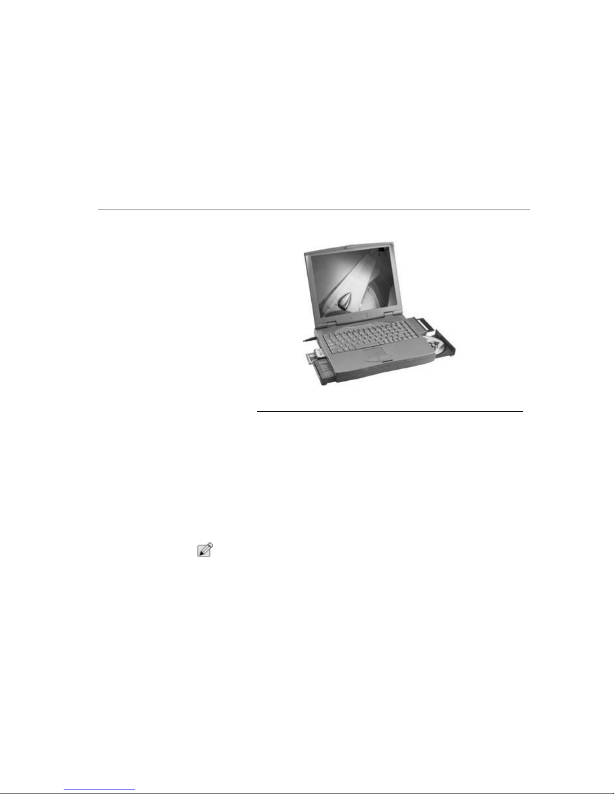
Figure 1. TransPort NX
Unpacking the TransPort
NX
The TransPort NX comes securely packaged in a sturdy shipping carton. Upon
receiving your TransPort NX, open the box and carefully remove the contents. If
anything is missing or damaged, please contact Micron Electronics immediately.
All systems should include the following items:
• The TransPort NX computer
• An AC adapter
• An AC power cord
• Main Battery
• Software and Micron Customer Resource Center CD and/or MRestore CD
• User’s manual
N
OTE
:
Items included may vary. Please check the packing slip included with your
TransPort NX for the exact items you should have received.
Page 12

Personal Inventory
Chapter One - Getting Started
12
Personal Inventory
This TransPort NX computer system is designed for years of productive and
pleasurable computing. Use this section to keep notes about details of your
purchase. Update this section when you add new options.
Date of Purchase:
____________________________
Micron Technical Support:
1-888-FIX-MYPC (1-888-349-6972)
Address:
Micron Electronics
900 East Karcher Road
Nampa, Idaho 83687
Technical Support File Library:
http://support.micronpc.com/library
Technical Support Internet Mail:
1. To send an E-mail to Technical Support, visit the Micron Electronics Website:
http://support.micronpc.com/contact/support.
2. Click on the
Support Department
for your specific need.
Web site:
www.micronpc.com
Record the System’s operating information:
Serial Number:
Order Number:
Bill Customer Number:
(On Packing Slip)
CPU Type:
__________________________________
Hard Disk Capacity:
__________________________
Memory Capacity:
___________________________
Page 13

Operating Environment
Chapter One - Getting Started
13
Operating Environment
You can use your computer under a wide range of environmental conditions.
However, to ensure long use and continued high performance, consider the
following factors when setting up your computer:
• Set the computer on a flat, stable surface. To prevent damage to the
computer’s hard disk drive avoid using the computer where it will be
exposed to strong vibration.
• Place the computer away from electromagnetic or radio frequency
interference (for example, television/stereo sets, copying machines, and air
conditioners).
• Avoid using or storing the computer where it will be exposed to extreme
temperatures. In particular, do not leave the computer in direct sunlight,
over a radiator, or near a heat source for a long period of time. High
temperature can damage the circuitry.
• Avoid exposing the computer to high or low humidity. Extreme humidity can
contribute to disk drive failure.
• If you are using the computer with the AC adapter, do not allow anything to
rest on the power cord. Do not place the computer where people can step
on or trip over the cord.
The openings on the computer are provided to protect the computer from
overheating. To ensure reliable operation, leave about 10 cm (4 inches) around
the computer for unobstructed air circulation. Avoid exposing the computer to dust
or smoke.
C
AUTION
:
If your system arrives in cold weather, do not apply power to the computer
or monitor until it has reached room temperature.
Heat, Cold, Humidity, and Glare
Find a spot for your computer that’s not too hot, too cold, too dark, or too bright.
Glare can make it hard to read the screen. Overheating can destroy computer
components, so allow plenty of room for air to circulate around the case. Do not
place your TransPort NX in direct sunlight.
Page 14

Connecting to a Power Source
Chapter One - Getting Started
14
W
ARNING
:
Do not expose the notebook to cold (frost) or heat, do not leave the
notebook in a car, and do not drop it, spill fluids on it, or open the case. This
can destroy the notebook and void the warranty. The system’s Liquid
Crystal Digital (LCD) video display may be damaged by exposure to intense
sunlight, which builds up excessive heat inside the display enclosure. Only
exposure to indirect or subdued sunlight is recommended.
Work Location
Your TransPort NX generally will run well wherever you’re comfortable. But
extremes of temperature and humidity can be challenging to your system’s parts.
There are, however, some things you can tolerate that the computer can’t —
things like static electricity, dust, water, steam, and oil. So, whenever you decide
to pull over for roadside computing, choose a clean, comfortable work area for
your system.
Connecting to a Power
Source
You can use the provided AC adapter to supply your computer with power from an
AC wall outlet. Your computer also comes with a rechargeable battery pack for
using the computer without an external power source.
Connecting the AC Adapter
Use the provided universal AC adapter to supply your computer with power from
an AC wall outlet. You can also use the AC adapter to charge the computer’s
battery pack.
The AC adapter converts high-level AC voltage to the much lower level DC
voltage appropriate for the computer. The adapter’s AC input voltage can range
anywhere from 100 to 240 volts, covering the standard voltages available in
almost every country.
The power cord for the AC adapter requires a two-hole grounded AC outlet. An
optional four or six-plug power strip is a convenient addition, especially if you have
only one wall plug and several devices that need electricity. You can buy power
strips with built-in electrical surge protection. This provides limited protection from
spikes in the local voltage that can cause damage.
To connect the computer to an external power source:
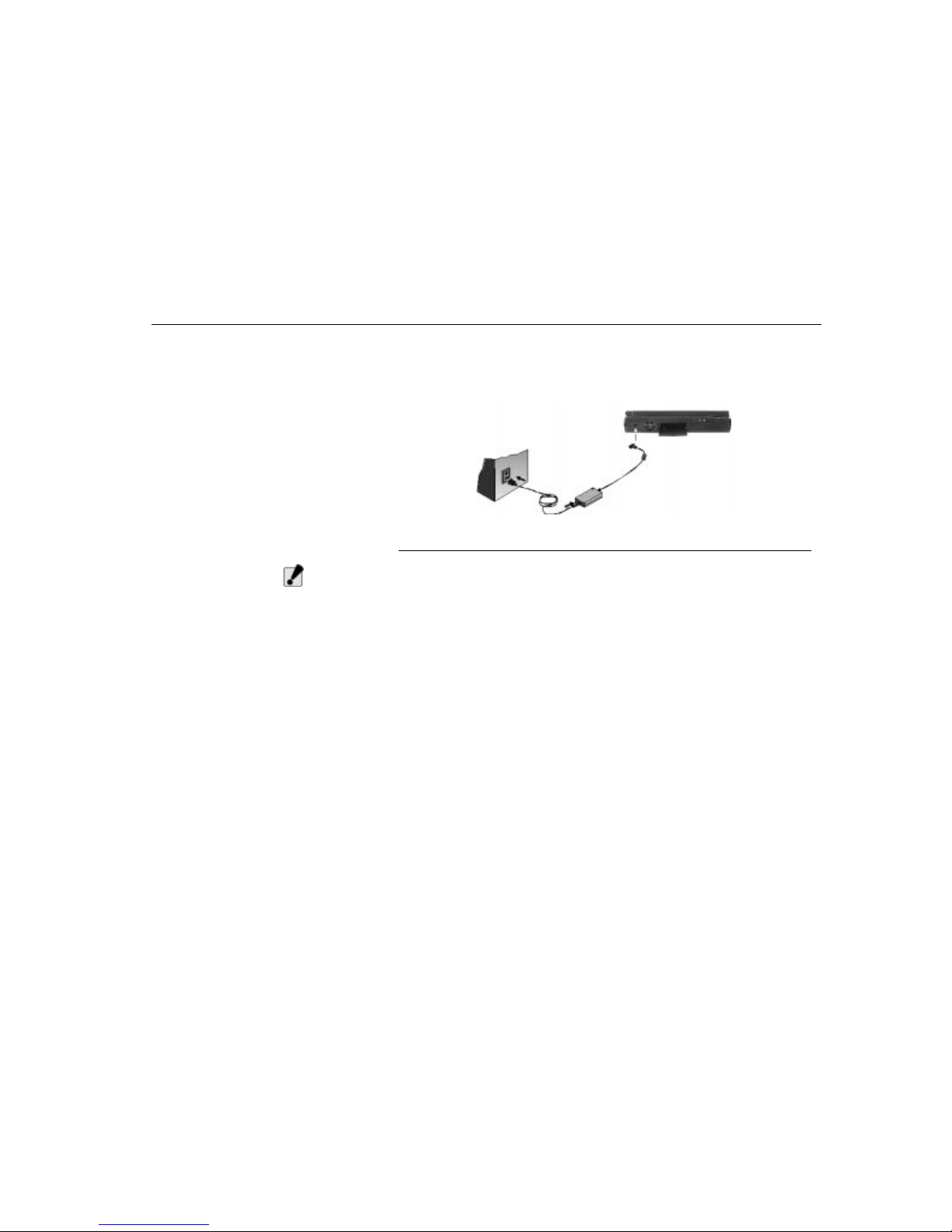
1. Plug the AC adapter’s connector into the DC-IN connector on the right side of
the computer.
2. Connect the power cord to the AC adapter and then to a wall outlet.
Page 15
Turning on the TransPort NX
Chapter One - Getting Started
15
Whenever possible, keep the AC adapter plugged into the TransPort NX and an
electrical outlet to recharge the battery. Although not necessary, it is also a good
idea to protect the display panel by always lowering it when the TransPort NX is
powered off.
Figure 2. Connecting the AC Adaptor
C
AUTION
:
The best kind of AC power source to connect your TransPort NX to is a UPS
(Uninterruptible Power Supply). Lacking this, use a power strip with a builtin surge protector. Do not use inferior extension cords as this may result in
damage to your TransPort NX. The TransPort NX comes with its own AC
adapter. Do not use a different adapter to power the computer, and do not
use the AC adapter to power other electrical devices. Damage to the
computer that is directly caused by using a different power source will not
be covered under warranty.
Surge Suppressors
Your computer has its own electrical filters, fuses, and protections, and even its
own built-in surge suppressor. We strongly recommend using a high-quality,
external surge suppressor. An external surge suppressor looks like an extension
cord with several grounded outlets. It will shield your computer from lightning
strikes, surges, shorts, and other electrical hazards.
Turning on the TransPort
NX
Before turni ng on you r compu ter , make s ure you are fa miliar with i ts fea tures . See
”Chapter Two - System Features” for more information.
Now that your TransPort NX is opened and connected to a power source, it’s time
to turn it on. Press the power button located above the system status indicator
panel. Hold the button down for a second or two and release.
Page 16

Turning on the TransPort NX
Chapter One - Getting Started
16
The Power-On Self Test (POST) will run automatically. After the POST is
completed, the computer reads the operating system from the hard disk drive into
computer memory. This is commonly referred to as “booting” a computer.
You are now ready to run software programs and use devices such as printers,
disk drives, and the CD-ROM.
To turn the TransPort NX off, save your work and close all open applications, click
on Start, then Shut Down. In the Shut Down Windows dialog box, select Shut
Down and click Yes.
C
AUTION
:
Never turn off or reset your TransPort NX while the hard disk or floppy disk
is in use and the FDD and/or HDD status icon is lit; doing so can result in
loss or destruction of your data.
Always wait at least five seconds after turning off your TransPort NX before
turning it back on; turning the power on and off in rapid succession can
damage the TransPort NX’s electrical circuitry.
Before you run your system for the first time on battery power, remove the
battery from its package and install it in the system. Recharge the battery
fully to prepare the battery pack for maximum service.
Except for PC cards, never connect or disconnect any equipment or
components while the system power is on.
When using the feet in the rear of the notebook, the computer will operate
cooler as the result of better ventilation. There is one fan on the left side of
the notebook, which will turn on when the CPU temperature exceeds 60
degrees. The fan will turn off when the CPU temperature is below 50
degrees.
W
ARNING
:
If the temperature continues to rise above the CPU allowable limit--either
due to a defective fan, the notebook being operated in an excessively hot
environment or a soft surface that covers the ventilation holes--then the
notebook will enter Save-to-disk mode (S2D). If there is no Zero-Volt DataSuspend Utility (ZVHDD) partition, the notebook will shut down and all
unsaved data will be lost. See “Zero-Volt Data-Suspend Utility (ZVHDD)” on
page 113.
Page 17

Ergonomics
Chapter One - Getting Started
17
Ergonomics
Ergonomics is the study of how people, with their different physical characteristics
and ways of functioning, relate to their working environment (the furnishings and
machines they use).
The goal of ergonomics is to incorporate comfort, efficiency, and safety into the
design of keyboards, computer desks, chairs, and other items in an effort to
prevent physical discomfort and health problems in the working environment.
If your budget permits, buy ergonomically designed furniture such as chairs,
shelves, and desks that fit your physical characteristics and work method. If you
are going to be sitting for extended periods of time, an ergonomically designed
chair may well be worth the extra expense.
You can, however, create an ergonomically improved workstation without
spending much money. The following tips will help you work effectively without a
lot of physical discomfort:
• Purchase a chair with armrests and good back support.
• Don’t slouch when sitting; keep your back straight.
• Place the LCD panel or external monitor so that it is a little above eye level
when using a word processor.
• Remember to Scroll Down often to ensure you are reading or typing at the
top of the screen; this will help to prevent neck strain.
• Try to place the LCD panel or external monitor so that there is little glare
from the sun on the monitor
• Walk around the room every hour.
• Every half hour look away from the computer screen for a few minutes.
• Place everything that you need to work within easy reach.
Page 18

18
Page 19
Opening the TransPort NX
Chapter Two - System Features
19
Chapter Two System Features
This section provides a description of the TransPort NX and an overview of the
notebook’s system features.
Opening the TransPort NX
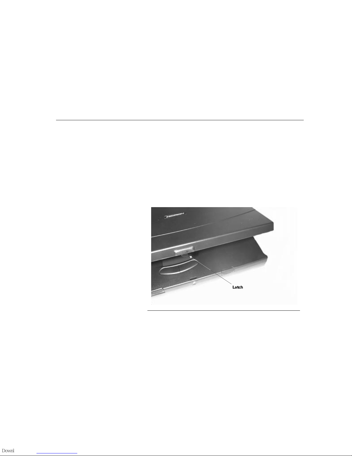
At the front of the TransPort NX you will find a retaining latch on the display panel
which locks the display in closed position when the TransPort NX is not in use.
Follow these steps to raise the LCD display cover:
1. Gently press the release button on the front of the notebook and raise the
display until it is at a comfortable viewing angle. To close the display, press the
top cover down until the latch snaps into place. The display folds down to form
a cover over the keyboard when the notebook computer is not in use.
2. When you close the notebook make sure there are no items on the keyboard
or palmrest, as these might damage the LCD panel.
Figure 3. Opening the TransPort NX
/DWFK
Page 20
Left View
Chapter Two - System Features
20
Left View
The following section describes the left side of the TransPort NX.
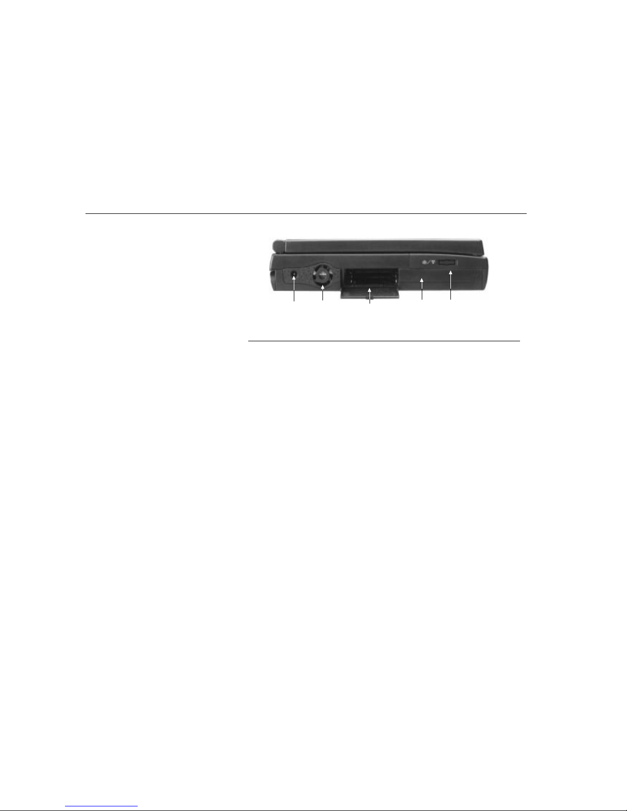
Figure 4. Left View of the TransPort NX
DC-Jack
Plug the AC adapter into this connector.
Fan
This fan prevents the TransPort NX’s CPU and other internal components from
becoming overheated. Keep this fan unobstructed to allow proper ventilation to
the NX’s internal components.
PCMCIA Slots Compartments
Open this cover to access the PCMCIA sockets. The computer’s PCMCIA sockets
let you extend the capabilities of your computer by inserting PC cards. The cards
are hot swappable, meaning you can change cards without having to reboot your
computer. There are a wide variety of PC cards available, including data storage,
fax/modem, Local Area Network (LAN), wireless communication cards, and more.
See “Using PCMCIA Cards” on page 38.
Main Battery
Y our TransPort NX comes equipped with a factory-installed battery pack module.
After the battery runs down, the module can be removed and replaced with a
charged battery. Additional battery packs are optional. See “Batteries” on page
64.
Fax/Modem (Optional)
If equipped, there will be a connector for modem and fax use. This allows you to
send information via the internet, conduct e-commerce, or simply surf the web, all
on your TransPort NX. See “Optional Fax/Modem” on page 75.
DC-Jack
Fan
PCMC IA Slots
Com
p
artments
Main
Batter
y
Fax/Modem
(Op
tional
)
Page 21
Right View
Chapter Two - System Features
21
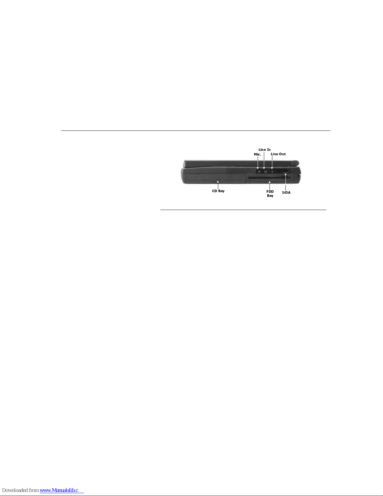
Right View
The following s ection describes the right side of the TransPort NX.
Figure 5. Right View of the TransPort NX
Microphone Jack
This mono microphone jack is used to connect an external microphone.
Line In
This jack is for auxiliary input. The auxiliary input can be used to connect an
external audio source (cassette player, CD player, etc.) to your TransPort NX.
With the proper software you will be able to record this input signal.
Line Out
This is for speaker output. You can plug amplified external speakers or
headphones into the speaker output jack, or connect the audio out jack to an
audio device such as a cassette recorder to record the TransPort NX’s audio
output.
CD Bay
Y our TransPort NX comes with a swappable 20X (or faster) 5.25" IDE CD-ROM
drive. See “Removable CD-ROM” on page 29.
FDD Bay
Y our TransPort NX has a 3.5" floppy disk (FDD) installed. The FDD is capable of
reading and writing 3.5" 1.44MB floppy diskettes. When the FDD is reading from
or writing to a disk, the FDD icon on the LED indicator panel will illuminate.
IrDA
The Infrared Data Port allows your TransPort NX to become truly wireless. You
can use this port to transfer large amounts of data very quickly to any other
machine (NX computers, printers, etc.) which is also equipped with an IrDAcompliant IR port. This allows you to print documents without any inconvenient
cable hookups.
&' %D\
)''
%D\
,U'$
0LF
/LQH ,Q
/LQH 2XW
Page 22
Rear View
Chapter Two - System Features
22
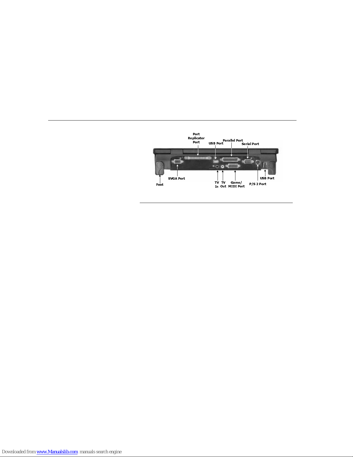
Rear View
The following section describes the rear view of the TransPort NX.
Figure 6. Rear view of the TransPort NX
Foot
The foot option allows for more comfortable, ergonomic use of the TransPort NX.
This not only improves the ergonomics when you type, but also helps cool the
notebook down. It is recommended that the feet be used.
SVGA
This port allows you to easily connect an external VGA/SVGA display monitor into
your TransPort NX using the 15-pin female connector.
Port Replicator Bay
Connect the optional port replicator to the 204-pin port replicator connector. This
will further enhance your TransPort NX’s portability by making it easy for you to
connect and disconnect peripheral devices to your TransPort NX.
USB Ports
Y our computer includes two Universal Serial Bus (USB) ports. USB is the latest
development in Plug-and-Play technology. It will eventually replace the need for
separate connectors for external keyboards, serial ports, and parallel (printer)
ports. With broad industry support, USB is sure to play an important role in the
design of future peripheral devices. As more and more of these devices become
available, your computer will be ready to use them.
Parallel Port
This port allows you to easily connect a parallel printer or plotter using this 25-pin
bi-directional female port.
Game/MIDI Port
This port allows you to easily connect games controllers for enhanced play.
)RRW
69*$ 3RUW
3RUW
5HSOLFDWRU
3RUW
79
,Q
79
2XW
86% 3RUW
*DPH
0,', 3RUW
3DUDOOHO 3RUW
6HULDO 3RUW
36 3RUW
86% 3RUW
Page 23
Bottom View
Chapter Two - System Features
23
Serial Port
This port is used to connect RS-232 serial devices to the TransPort NX. Three
types of serial devices are; external mice, serial printers, and fax/modems.
PS/2 Port
This connector accepts an external keyboard with a 6-pin (PS/2-compatible)
connector. To connect a keyboard with a 5-pin connector, use a 5-pin to 6-pin
transfer cable. You can connect an external keyboard, numeric keypad, or IBM
PS/2 compatible mouse to this socket, marked with the keyboard/mouse icon.
N
OTE
:
After a PS/2 mouse is plugged into the system, it will not be ready for use until you
press [FN]+[F12]. Only the pointing stick or the PS/2 mouse will be available at
any one time. If you wish to resume using the pointing stick, press [FN]+[F12]
again. The touchpad will remain active with either option.
TV OUT / In Ports
These composite Ports allow you to view the NX display on a TV, or a TV on the
NX display. See “Chapter Six - Optional Accessories” on page 71.
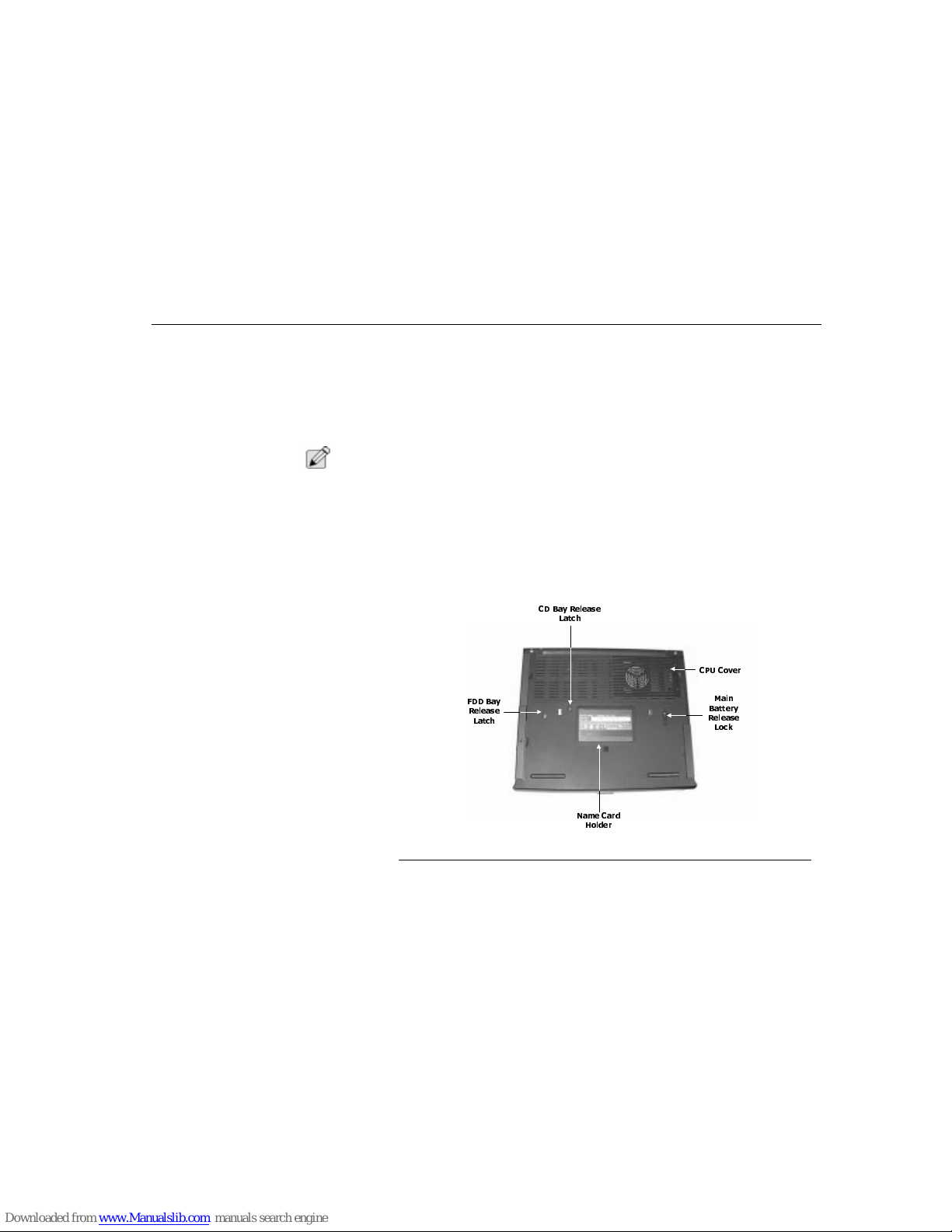
Bottom View
The following section describes the bottom view of the TransPort NX.
Figure 7. Bottom View of the TransPort NX
&38 &RYHU
0DLQ
%DWWHU\
5HOHDVH
/RFN
1DPH &DUG
+ROGHU
)'' %D\
5HOHDVH
/DWFK
&' %D\ 5HOHDVH
/DWFK
Page 24
Interior Features
Chapter Two - System Features
24
CD-ROM Release Latch
Slide the CD-ROM release latch to release the CD-ROM drive or DVD-ROM drive.
FDD BAY Release Latch
Slide this latch to release the FDD drive, LS-120 drive, Zip drive, second HDD, or
second battery.
Name Card Holder
This slot holds a card containing the unit serial number and FCC information.
CPU Cover
This covers the CPU compartment providing easy access to allow for upgrades.
C
AUTION
:
Only Micron service technicians should open this cover.
Main Battery Release Latch
Slide the battery lock to the left when removing the battery module from the
battery bay.
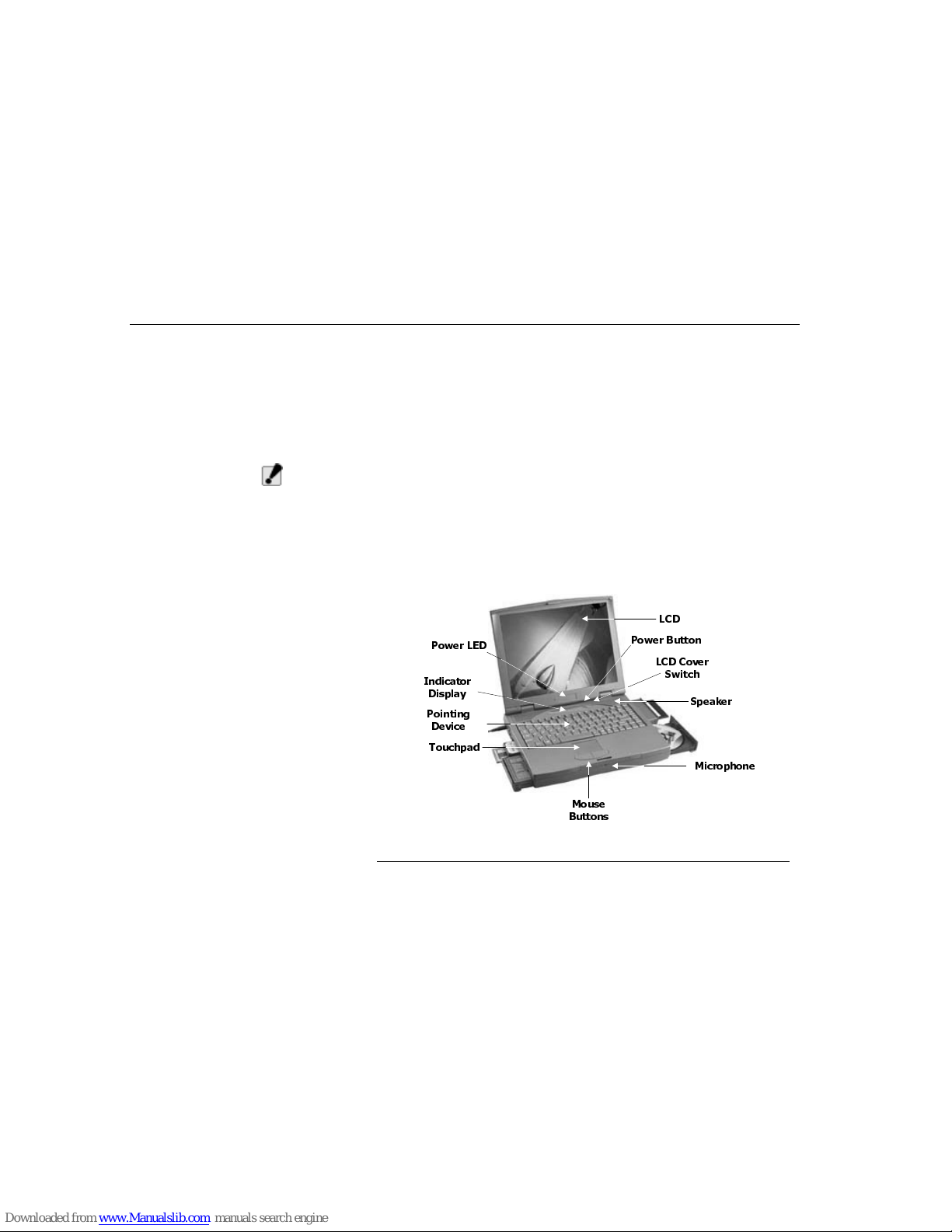
Interior Features
The following section describes the TransPort NX features viewable when the
cover is open.
Figure 8. Interior Features of the TransPort NX
7RXFKSDG
0RXVH
%XWWRQV
6SHDNHU
/&' &RYHU
6ZLWFK
3RZHU /('
/&'
3RZHU %XWWRQ
0LFURSKRQH
3RLQWLQJ
'HYLFH
,QGLFDWRU
'LVSOD\
Page 25
Interior Features
Chapter Two - System Features
25
LCD
The LCD assembly comes with the following display option:
• 15.1" TFT XGA, 1024 x 768 x 64K color resolution
Power Button
The power button on your notebook has more uses than just ON and OFF, for
security and power management reasons. See “Power Saving Modes” on page
61.
Power ON
If the notebook is OFF (no power on light) press down the power button to turn on
the notebook.
Power OFF
To turn off the notebook press the power button. If the notebook doesn’t turn off
immediately due to the notebook hang (lock-up) or another reason, then press
down the power button for 5 seconds until the notebook turns off. Please note that
when the system is still in POST stage, the user has to press the button for 5
seconds to power off the system.
Power LED
Indicates when the unit is receiving power or is in Standby mode.
Indicator Display
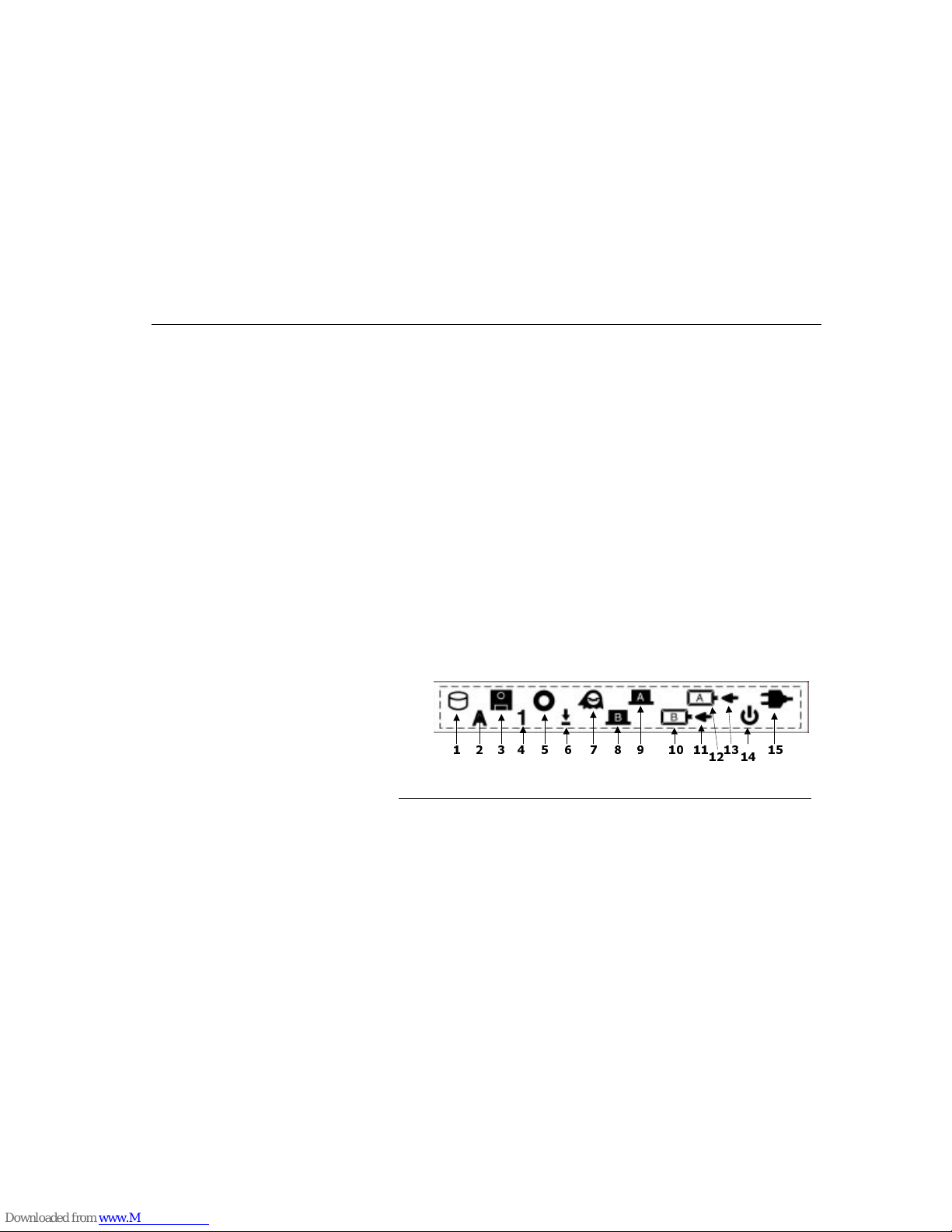
The system status indicator panel, located below the LCD screen, keeps you
informed of the computer’s operating status. There are also three system status
indicators (power, suspend, and battery charge) on the LCD cover.
Figure 9. Indicator Display
1.
HDD
-
This indicator lights when the system accesses the internal HDD.
2.
Caps Lock
-
This indicator lights when the Caps Lock function is active. Press
the Caps Lock key again to deactivate this function.
3.
FDD
-
This indicator lights when the system accesses the FDD.
Page 26

Interior Features
Chapter Two - System Features
26
4. Number Lock -
This indicator lights when the embedded keypad is toggled
“ON” or an external keypad is in numeric mode.
5. CD-ROM -
This indicator lights when the system accesses the internal CD-
ROM.
6. Scroll Lock -
This indicator lights when the Scroll Lock function is active.
Press the Scroll Lock key again to deactivate this function.
7. S2R Mode -
This indicator lights when the notebook is in the Save to RAM
mode.
8. PCMCIA Card Slot B -
This indicator lights when a PCMCIA card is installed.
9. PCMCIA Card Slot A -
This indicator lights when a PCMCIA card is installed.
Only slot A supports the ZV card.
10.Secondary Battery Icon -
This indicator lights when the secondary battery
pack is installed at System ON Mode or Power source is Adapter.
11. Secondary Battery Indicator -
This indicator lights when the primary (main)
battery pack is installed.
12.Main Battery Icon -
This indicator lights when the primary (main) battery pack
is installed.
13.Main Battery Charge Indicator -
This indicator lights when the Main Battery is
in charge mode. If this indicator flickers continuously for more than eight hours,
then this indicates that the battery may be damaged.
14.Power On/Off Icon -
The icon indicates a status of Power On or Off.
15.AC Power -
This indicator lights when the system is operating on AC power.
Stereo Speakers
The internal speakers are located directly below the LCD panel on the left and
right side of the TransPort NX. These speakers provide true stereo sound.
Touchpad
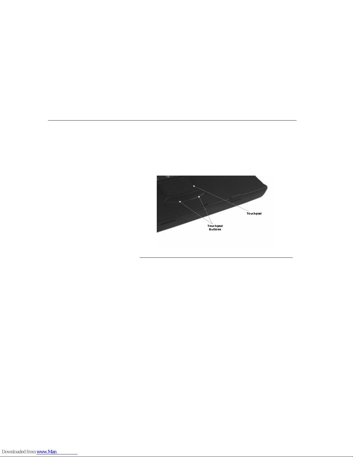
The dual-button touch pad is located below the keyboard. The touch pad is
hardware-compatible with the IBM PS/2 mouse and software-compatible with the
Microsoft mouse. See “Touch Pad” on page 34.
N
OTE
:
Intellimouse (in Wheel Mode) may cause erratic behavior if used in conjunction
with the pointing stick, and/or touchpad. Please select [FN]+[F12] to switch to
external PS/2.
Page 27

System Features
Chapter Two - System Features
27
LCD Cover Switch
Slide this latch to the right to open the LCD cover.
Your TransPort NX computer is equipped with a replaceable color Liquid Crystal
Display (LCD) screen. The LCD panel supports 1024 x 768 x 64K LCD resolution
utilizing an AGP display adapter. The LCD screen and XGA display circuitry let
you view text and the latest high resolution video images.
Mouse Buttons
The buttons below the touch pad correspond to the left and right buttons on a
standard mouse.
Microphone
The built-in microphone is located to the right of the touch pad.
System Features
This section provides an overview of the TransPort NX’s features. For detailed
technical information see “Appendix A - Specifications” on page 129.
Central Processing Unit (CPU)
The microprocessor (CPU) is the key hardware feature; it is the brain of the
computer, performing all the computing functions and orchestrating the actions of
the system.
The TransPort NX supports the Celeron, Pentium II, Pentium II PE and Mobile PIII
processors. All supported Intel processors are available with MMX technology.
The MMX media enhancement technology was designed specifically for faster
processing of multimedia and communications tasks. The TransPort NX also
employs the Intel 440BX core logic.
CPU Upgrade
Your TransPort NX supports Intel’s latest CPU technology, the MMO (Mobile
Module). This makes it very easy for your dealer to exchange the CPU for you.
There are two types of MMO modules from the Intel, your notebook is using the
latest MMC-2 400-pin connector.
W
ARNING
:
We do not recommend that you upgrade the CPU by yourself. Please
consult your dealer or an authorized service center for notebooks.
The connector on the MMO is very sensitive, and if handled improperly may
be broken (thus making the MMO useless).
Page 28
System Features
Chapter Two - System Features
28
L2 Cache
The TransPort NX supports a 512KB L2 write back cache with synchronous
pipeline burst mode, 128 KB or 256KB of full bus speed on-die L2 write back
cache with synchronous pipeline burst mode.
Upgradeable System Memory
The TransPort NX has a 64-bit memory bus. Memory can be upgraded to 384MB
by the following options:
• One, two or three 32, 64, or 128MB 144-pin, 3.3V, SDRAM SO-DIMM
modules.
When you want to upgrade memory: Turn off the computer, open the palmrest,
and lift the keyboard carefully without scratching the very fragile LCD. Follow
either procedure below to add or remove memory.
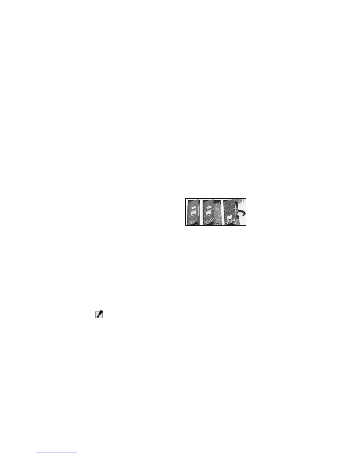
You will now see three memory slots as follows:
Figure 10. Memory Slots
To Remove Memory
1. Press both metal tabs on either side of the memory module away from the
module until the module pops free.
2. Remove the module carefully at a 45 degree angle. Avoid touching the
SDRAM module on any of its static-sensitive circuitry.
3. Store the module in a static free bag.
To Install Memory
1. Ensure the key on the memory slot is lined up with the key on the module
(there will be two slots on the module; it will only fit into the slot one way).
2. Insert at a 45 degree angle.
3. Once it is in the slot, press down the module. You will hear a small clickwhen
the memory module is firmly in place.
W
ARNING
:
Use only SDRAM memory modules!
Page 29

System Features
Chapter Two - System Features
29
VGA Graphics Accelerator
The video subsystem includes 8MB of SGRAM video memory, a 3D graphics
engine, and a high performance AGP 2X Bus with support for full power
management. The video subsystem supports a ZV (Zoomed Video) port and
simultaneous display (Simulscan) in all video modes, up to 1024x768 resolution.
Removable Hard Disk Drive
Module
The TransPort NX comes with a 2.5" (17mm maximum3 height) hard disk
installed. The HDD supports PIO mode 4 and ultra DMA 33. The hard drive can
also be easily removed and replaced with a second hard drive for expansion. The
TransPort NX supports HDDs with capacities of 1.44GB or above, and supports
Ultra DMA/33 transfers allowing data transfer rates up to 33 MB per second.
Removable CD-ROM
The high speed built-in CD-ROM drive can be swapped with a Digital Versatile
Disk (DVD) ROM drive.
Audio System
The TransPort NX’s audio system includes a sophisticated built-in ESS PCI
stereo audio-sound generator compatible with Sound Blaster and Microsoft
Sound System. The sound system includes amplified output, two built-in 1 watt
stereo speakers, manual volume control, and built-in microphone.
Audio Ports
The TransPort NX comes with four audio jacks: a line in for connecting audio
equipment for use with the multimedia system; and a line out for connecting
stereo speakers, a headphones jack, and a microphone jack.
Battery and AC Power System
The TransPort NX can operate on two power sources; an AC adapter, or the
rechargeable battery module pack.
The AC adapter has automatic 100-240V line switching, which will automatically
check the power voltage coming out of the wall and adjust it to the voltage your
computer requires.
The system will automatically recharge the battery pack in the TransPort NX by
using the AC adapter. By using the power management features, the TransPort
NX can operate on battery power for approximately two to three hours. For
extended battery-powered operation, additional battery modules may be
purchased. See “Power Saving Modes” on page 61.
Security
The password protection feature of your TransPort NX prevents unauthorized
people from accessing important files and information on your computer. See
“Security Option” on page 48.
Page 30

System Features
Chapter Two - System Features
30
Input/Output Devices
Most of the TransPort NX’s hardware features can be described as input and
output devices. An input device is a hardware device used to enter information to
be processed by the computer. Examples of input devices are the keyboard and
the touch pad. An output device, (LCD display, monitor, or printer) receives data
from the computer and displays the information in a human-readable format.
Other Devices
Other hardware components such as the serial port, parallel port and disk drives
are both input and output devices. They can be used for transferring data to and
from the computer.
LCD Display
The TransPort NX comes with a color LCD display panel.
The LCD screen display results can be adjusted by changing the LCD panel
angle, and the display brightness.
LCD Care
LCD screens are delicate devices that need careful handling. Please take the
following precautions:
• When you are not using the computer, keep the LCD screen closed to
protect it from dust.
• If you need to clean your LCD screen, use a soft tissue to gently wipe the
LCD surface.
• Do not put your fingers or sharp objects directly on the surface or spray
cleaner onto the display.
• Do not press on or store any objects on the cover when it is closed. Doing
so may cause the LCD to break.
External CRT Display
You can hook up an external monitor through the 15-pin CRT connector. Three
configurations are available:
• LCD only
• Simultaneous display of the LCD screen and CRT monitor
• CRT only
Display Resolution Color Depth
15” TFT XGA 1024x768 64K color
TABLE 1. LCD Display
Page 31
TransPort NX Keyboard
Chapter Two - System Features
31
Y ou can switch between these display configurations by pressing the key
combination [Fn] + [F12].
TransPort NX Keyboard
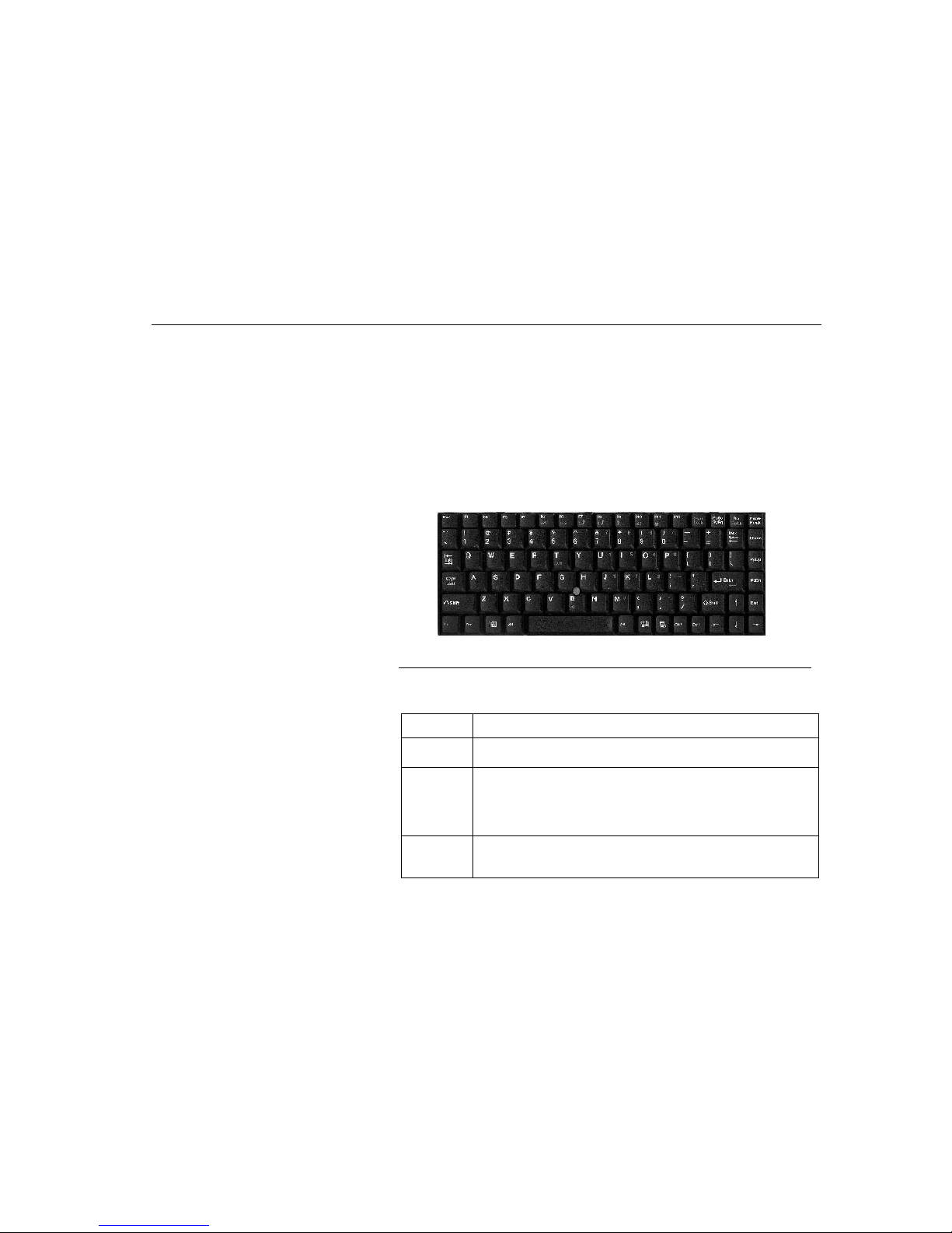
The TransPort NX’s keyboard uses a standard QWERTY layout with the addition
of special function keys and an embedded numeric keypad, and supports
Windows 95 by incorporating the two Windows specific keys so you can take
advantage of many of the time-saving features of Windows 95.
The QWERTY layout means the alphanumeric keys located on the keyboard are
in the same position as those found on a standard typewriter. This section covers
the TransPort NX keyboard and identifies several keys which you will commonly
use when working with either the disk operating software or other software.
Figure 11. TransPort NX Keyboard
Description of Function Keys
Key Descriptions
[Esc] Use the escape key to cancel any specific command you may have just
keyed in.
[PrtSc/SysRq] Pressing this key will cause whatever is on the screen at the time to be
printed. In Windows 95,98, or NT the Screen will be copied to the
clipboard. Note that in some software programs, this key may be used
in conjunction with other keys for other specific functions. To use
SysRq, press the [Fn] key and the [PrtSc/SysRq] key together.
[Scroll Lock] When Scroll Lock is engaged, pressing the cursor control keys moves
the cursor by fields of text . Press t he scro ll loc k key onc e to eng age thi s
mode. Pressing it a second time will disengage the scroll lock function.
TABLE 2. Key Descriptions
Page 32
TransPort NX Keyboard
Chapter Two - System Features
32
Windows 95 Keys
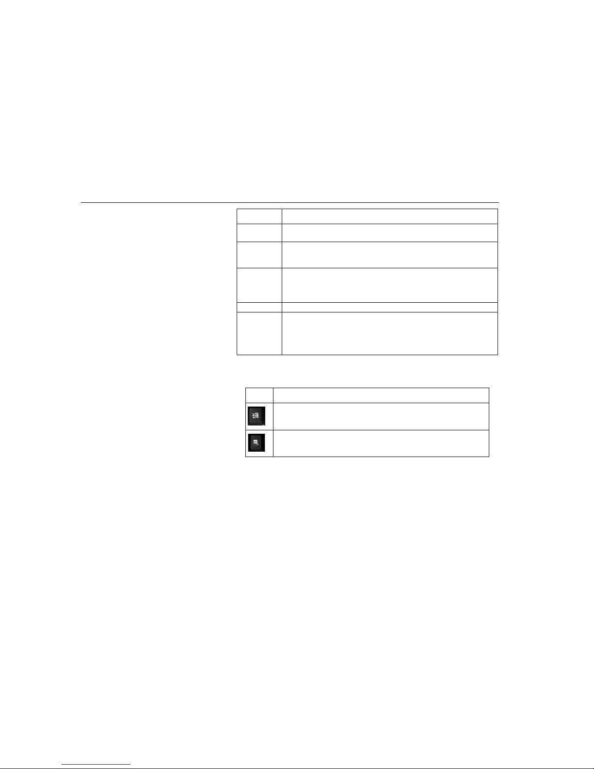
There are two special Windows 95 keys on the keyboard.
[Pause/
Break]
The break key is used in conjunction with the control key ([Ctrl] +
[Break]) to cancel a command.
[Alt] Used by itself, the alternate key has no effect in carrying out any
commands, but functions with the [Ctrl] and [Del] key ([Alt] + [Ctrl] +
[Del]) to reboot or restart your operating system program.
[Caps Lock] The [Caps Lock] key corresponds to a typewriter’s shift lock key, but it
only affects letter keys. Even with the [Caps Lock] key engaged, if you
want to generate the s ymbols an d punctu ation ma rks abov e the nu mber
keys, you must still use the [Shift] key.
[Shift] Use this key to type letters in upper case.
[Ctrl] Used by itself, the control key has no effect in carrying out any
commands. Like the [Alt] key , it is always used in comb ination with othe r
keys. Its function depends mainly upon the type of software you are
currently using. Refer to the user’s manual of the software you are us ing
for details on how to use this key.
Key Descriptions
TABLE 2. Key Descriptions
Key Definitions
The key with the Window 95 logo activates the
Start
menu button on
the bottom left of the screen.
The other key, which looks like a menu with a sm al l arrow, activates the
properties menu and is equivalent to pressing the right mouse button
while pointing at any object on the Windows desktop.
TABLE 3. Windows 95 Keys
Page 33
TransPort NX Keyboard
Chapter Two - System Features
33
Hot Key Controls
Function Keys
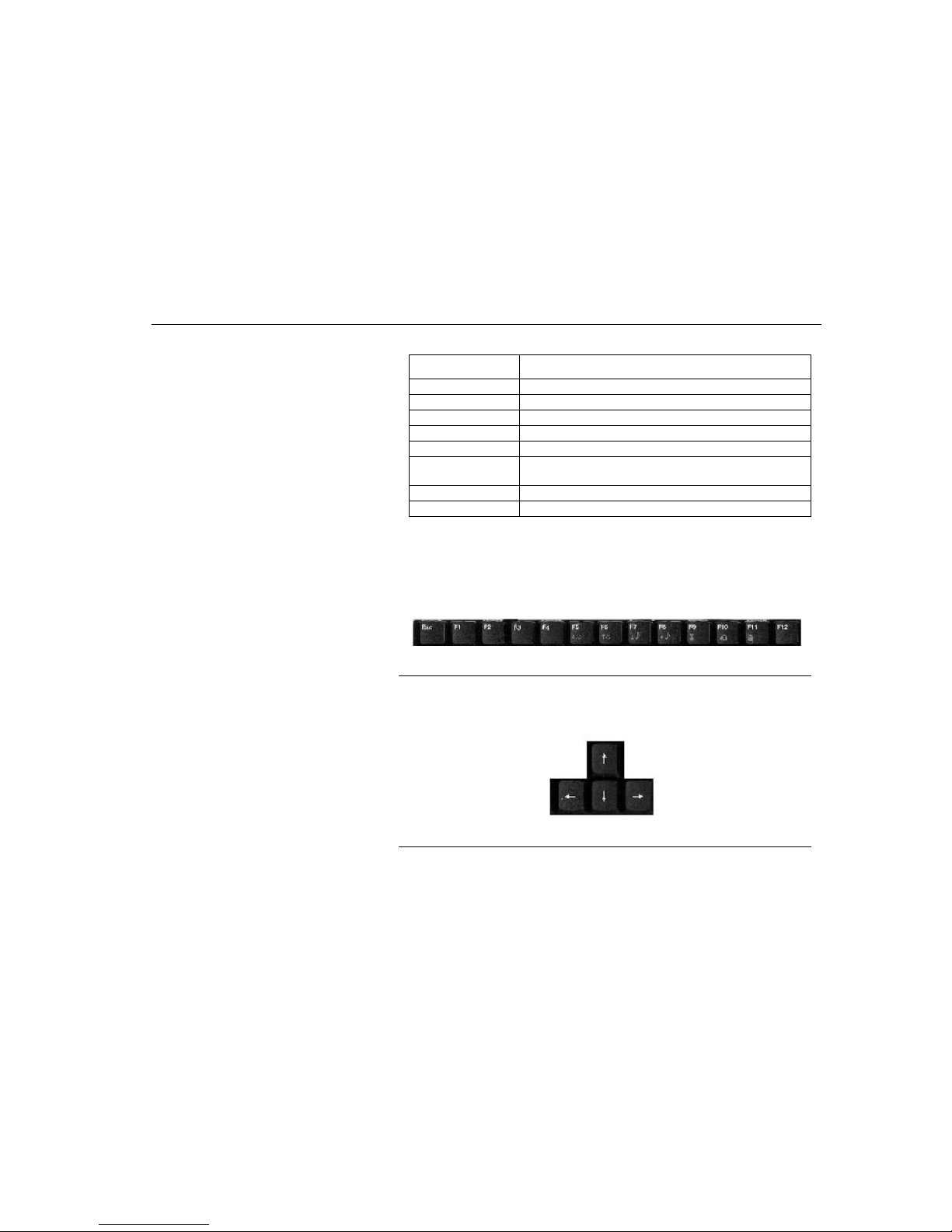
Notice the twelve function keys in the top row of the keyboard, appearing in
sequence from left to right. The functions of these keys vary with respect to the
operating system and software in use. Refer to the appropriate software user’s
manuals for more detailed information on function key definitions.
Figure 12. Function Keys
Cursor Keys
The four direction (arrow) keys control the movement of the cursor on the screen.
They do not affect the displayed characters.
Figure 13. Cursor Keys
Key Combinations Definitions
[Fn] + [F1] NTSC/PAL TV Output mode.
[Fn] + [F5] Increases brightness.
[Fn] + [F6] Decreases brightness.
[Fn] + [F7] Increases the speaker volume.
[Fn] + [F8] Decreases the speaker volume.
[Fn] + [F12] Toggles between internal pointing stick and external PS/2
mouse.
[Fn] + [B] Enables/disables speaker and battery low warning beeps.
[Fn] + [T] Toggles display to CRT, CRT & LCD or LCD.
TABLE 4. Hot Key Controls
Page 34
Touch Pad
Chapter Two - System Features
34
Embedded Numeric Keypad
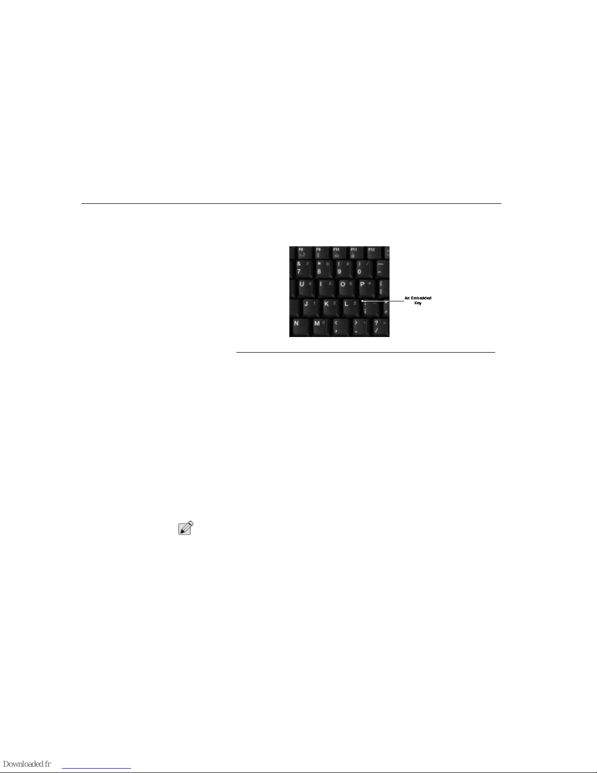
The embedded numeric keypad consists of 15 keys that make number intensive
input more convenient. Like the [Num Lock] key, these keys are labeled in blue on
the keycaps. Numeric assignments are located at the upper right of each key.
Figure 14. Embedded Keyboard
When the numeric keypad is engaged, the
NumLock
icon will appear in the
System Window
. The keypad is activated by pressing the [Fn] + [NumLk] key. If
an external keyboard is connected, pressing the NumLock key on either the
TransPort NX or external keyboard will enable/disable NumLock of both
keyboards in unison. To disable the TransPort NX numeric keypad while keeping
the keypad on an external keyboard activated, use the [Fn] + [NumLk] hot key on
the TransPort NX keyboard.
System Status Window
Located above the keyboard, the
System Status
window display panel informs
you of the TransPort NX’s current operating status at a glance. Upon activating a
certain function, a symbol or icon corresponding to that function will appear in the
system window until you deactivate that feature. The symbol will remain in the
window indicating that the feature is engaged.
Touch Pad
The TransPort NX’s integrated touch pad is compatible with the PS/2 mouse. A
device driver is not required for working with application software that supports
PS/2 mouse operation.
N
OTE
:
Intellimouse (in Wheel Mode) may cause erratic behavior if used in conjunction
with the pointing stick, and/or touchpad. Please select [FN]+[F6] to switch to
external PS/2.
$Q (PEHGGHG
.H\
Page 35

Touch Pad
Chapter Two - System Features
35
Using the Touch Pad
The touch pad is a pressure sensitive pointing device that provides all the features
of a two-button mouse. Its primary function is to move the cursor around the
screen. To use your touch pad:
1. Place your fingers on the keyboard in the normal typing position. The touch
pad is easily accessible by moving either your left or right thumb off the space
bar and on to the touch pad.
2. Gently move your thumb across the pressure-sensitive touch pad in the
direction you want the cursor to move. The pad detects the change in
pressure and moves the cursor in the corresponding direction.
3. With a conventional mouse, selections are usually made by double-clicking the
mouse’s left button. The touch pad also supports this feature.
4. The touch pad offers another method of making selections in a software
program. It is called double-tapping. This function corresponds to doubleclicking with a mouse. Once the cursor has been moved to the object you
want to select, lightly double-tap the pressure sensitive touch pad to select the
desired object and start the application.
5. The buttons located below the touch pad are essentially the same in function
as those on a two-buttoned mouse. Clicking these buttons makes selections,
drags objects, or performs a variety of other functions depending on the
software. To select an object, first move the pointer over the object you want to
select, and then press the left button one time. The functions of these buttons
are software specific.
6. Double-clicking is a common technique for selecting objects or launching
programs from icons. Once you have moved the pointer over the object you
wish to select, rapidly press the left button twice.
There are two ways to drag:
• Move the pointer to the desired location then press down the left button.
While still holding down the left button, move the pointer to the desired
location. Then release the button.
• Move the pointer to the desired location. T ap the touch pad twice quickly as
if you were double-clicking, however do not remove your finger after the
second tap. While maintaining contact with the touch pad, move the pointer
to the desired location. Lift your finger to finish dragging.
Page 36
Touch Pad
Chapter Two - System Features
36
Touch Pad Precaut ions
The touch pad is a pressure sensitive device. If not properly cared for, it can be
easily damaged. Please take note of the following precautions.
• Make sure the touch pad does not come into contact with dirt, liquids or
grease.
• Do not touch the touch pad if your fingers are dirty.
• Do not rest heavy objects on the touch pad or the touch pad buttons.
You can use the touch pad with Microsoft Windows as well as non-Windows
applications.
Figure 15. Touchpad and Touchpad Buttons
Installing a Touch Pad Driver
The touch pad is internally connected to the computer’s PS/2 port. As with a
mouse, the touch pad must be enabled and configured in order to function
correctly with your software.
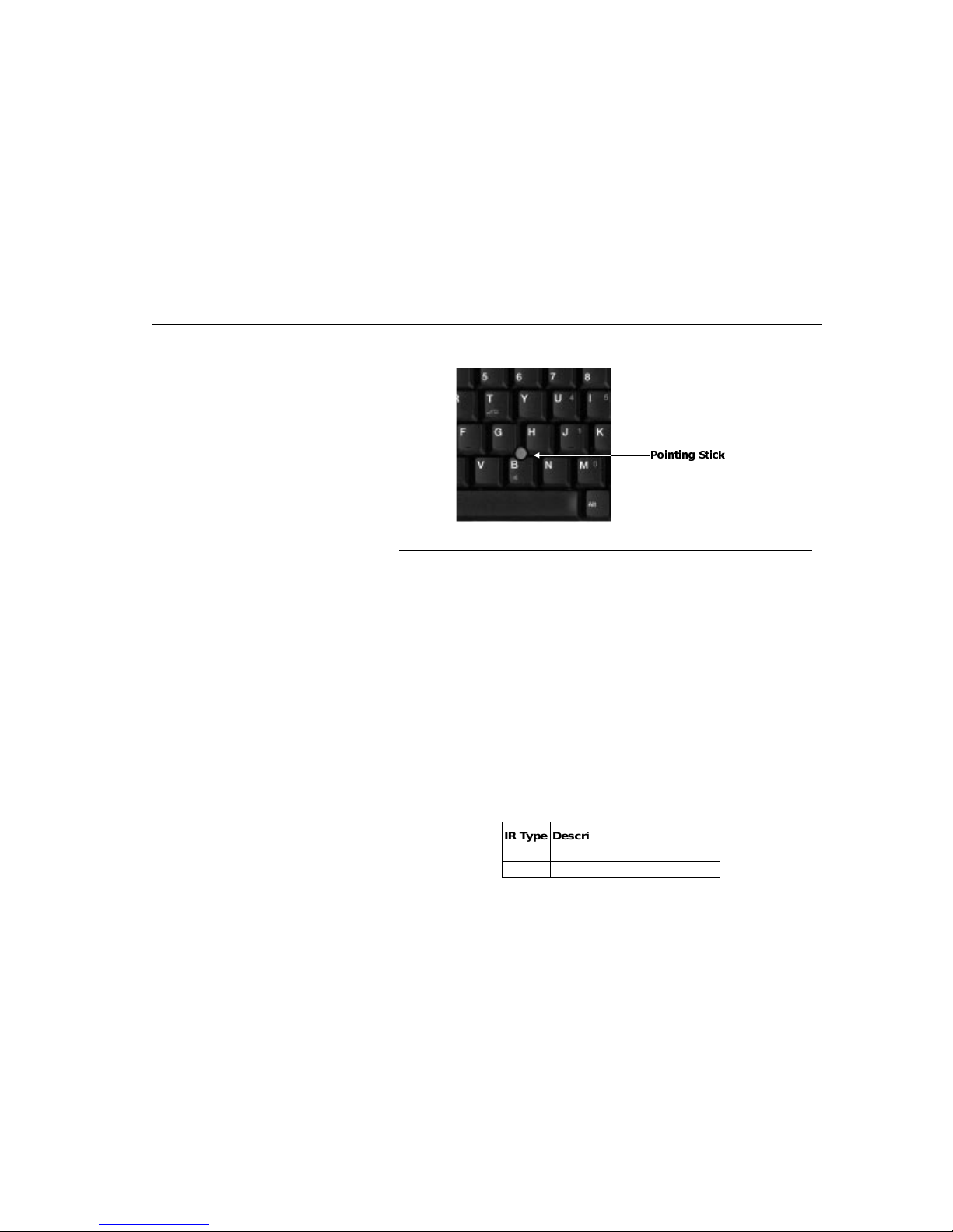
Using the Stick Pointer
1. Use your index finger to gently push the pointing stick in the direction you wish
the cursor to move.
7RXFKSDG
%XWWRQV
7RXFKSDG
Page 37
IR Communication
Chapter Two - System Features
37
2. The stick point buttons work in conjunction with the stick point, just like the
touchpad.
Figure 16. Pointing Stick
3. You can use the touchpad with Microsoft Windows as well as non-Windows
applications.
IR Communication
The TransPort NX is equipped with an Infrared (IR) communication module
located on the left side of the TransPort NX.
The IR module consists of one Light Emitting Diode (LED) and one photo sensor.
The LED functions as a transmitter and the photo sensor acts as a receiver. The
transmitter emits a signal stream consisting of data in the form of pulses of
infrared light. The receiver picks up pulses of infrared light transmitted by other IR
modules.
Use the IR module to perform wireless, serial communication. Use an FIRspecified application to transmit or receive data via the TransPort NX’s FIR
module.
The following table briefly describes each of the IR modes available. You must set
these modes in BIOS. Please refer to ”Chapter Three - Running BIOS Setup” for
information on the BIOS Setup program.
3RLQWLQJ 6WLFN
IR Type Description
FIR Fast Infrared
IrDA Infrared Data Association Protocol
TABLE 5. IR Modes
Page 38

PCMCIA Cards and Expansion Sock ets
Chapter Two - System Features
38
Follow the guidelines listed below when using the infrared communication module
to transmit or receive data.
• Make sure the infrared communication field in the BIOS Setup program is
set to FIR. Refer to ”Chapter Three - Running BIOS Setup.”
• Ensure that the TransPort NX’s FIR module is properly lined up with the
other device’s infrared communication module. The angle between the two
Infrared Communication modules should not exceed ±15°.
• There should be a clear, unobstructed path between the two infrared
communication modules; otherwise the optical signal will be blocked.
Likewise, do not place anything between the two infrared communication
modules during data transmission.
• Make sure the distance between the TransPort NX’s FIR module and the
other device’s infrared communication module does not exceed one meter.
• Do not move either the TransPort NX or the other device during
transmission of data, otherwise data transmission will be distorted resulting
in loss of data or a system crash.
• An error can occur if FIR transmission is conducted in an environment with
high levels of noise. To avoid transmission errors do not transmit infrared
communication signals near equipment with compressors, such as
refrigerators or air conditioners.
PCMCIA Cards and
Expansion Sockets
The TransPort NX features two PCMCIA (Personal Computer Memory Card
International Association) expansion sockets designed to interface with one or two
Type II cards, or one Type III card. This sophisticated innovation allows you to
expand and customize your computer to meet a wide range of computing needs
without sacrificing portability. PC cards accommodate a number of expansion
options. Memory cards, modems, hard disks, and network adapters are just a
small sample of the PC card products available on today’s market.
Using PCMCIA Cards
The PCMCIA (Personal Computer Memory Card International Association) is a
widely accepted industry standard that defines the design and operation of PC
cards. PC cards that conform to the PCMCIA standard are plug-and-play devices,
which means that they can be inserted into the PCMCIA expansion sockets while
the computer is powered on. This type of hot insertion does not apply to all PC
cards. Refer to the documentation that came with your PC card for detailed
information on the operation of PC cards.
Page 39

Preparing the TransPort NX for Transport
Chapter Two - System Features
39
Inserting a PCMCIA Card
When properly configured, the computer will emit a medium tone followed by a
high tone when a PC card is inserted. When you eject a card, the computer will
emit a high tone followed by a medium tone. You can insert and remove a PC
card whether the computer is turned on or off.
1. Hold the PCMCIA card with the label side up and the connector side toward
the socket.
2. Align the card connectors with the appropriate socket and carefully slide the
card into the socket until it locks into place. The system will beep once to
indicate that it has detected the PC card.
3. The Eject buttons are located next to each slot on the right. Note that there are
two Eject buttons, one per slot. To remove a PC card push the respective Eject
button, the button will pop out, push the button again to eject the PCMCIA. The
upper button will eject a Type II PCMCIA card from the upper socket. The
lower button will eject a Type II or Type III PCMCIA card from the lower socket.
Then remove the card and store it properly.
Preparing the TransPort
NX for Transport
To prepare the computer for transport, you should first disconnect all peripherals.
Make sure the computer is turned off before you do this. After disconnecting all
peripherals, close the rear port covers to protect the connectors.
The TransPort NX’s hard disk head is self-parking. This means that the TransPort
NX can be directly turned off from the DOS prompt. Close the LCD panel and
check that it is latched securely to the computer. Make sure the floppy drive does
not contain a diskette. When a diskette is inserted in the floppy drive the Eject
button pops out. If you attempt to transport the TransPort NX with a diskette in the
drive, you risk damaging the Eject button.
The computer has an optional soft carrying case. It will keep out dirt and dust and
protect your TransPort NX’s casing from becoming scratched or cracked.
If you intend to use battery power, be sure to fully charge the battery pack and any
spares. Remember the adapter charges the battery pack as long as it is plugged
into the computer and an AC power source.
Page 40

Power-on Self Test
Chapter Two - System Features
40
Traveling with the TransPort NX
For safety, security, and convenience when traveling with your computer, follow
these guidelines:
• Before traveling, save your data by backing it up onto floppy diskettes.
• Take along an extra backup copy of your data.
• Do not travel with a diskette in the floppy disk drive.
• Do not transport the TransPort NX with the power on. This may result in
loss of data and/or damage to the hard disk drive.
• Before traveling, disconnect the AC adapter from the computer.
• Always carry either a spare fully charged battery pack or the AC adapter.
• When carrying the computer, take care not to bump it into things. The
computer cannot take the kind of treatment that you might give a briefcase.
• Whenever possible, hand-carry the computer in its carrying case.
• If you must ship your computer as freight or baggage, pack it carefully. Use
the original cartons and foam cushions, if possible. If they are not available,
use sturdy cartons and cushion the computer well on all sides.
Power-on Self Test
The Power-On Self Test (POST) runs every time you turn on the computer. The
POST checks memory, the main system board, the display, the keyboard, the disk
drives, and other installed options.
A few seconds after you turn on your computer, a copyright message appears on
your display screen. A memory test message will appear next. The test continues
until all installed memory is tested. Normally, the only test routine visible on the
screen will be the memory test.
Two kinds of malfunctions can be detected during the POST:
• Error messages that indicate a failure with the hardware, the software, or
the BIOS. These critical malfunctions prevent the computer from operating
at all or could cause incorrect results. An example of a critical error is a
microprocessor malfunction.
• Messages that furnish important information (such as memory status,
power-on, and boot processes). These non-critical malfunctions are those
that cause incorrect results that may not be readily apparent. An example
of a non-critical error would be a memory chip failure.
In general, if the POST detects a system board failure (a critical error), the
computer halts and generates a series of beeps. If failure is detected in an area
Page 41

Operating System
Chapter Two - System Features
41
other than the system board (such as the display, keyboard, or an adapter card)
an error message is displayed on the screen and testing is stopped.
The POST does not test all areas of the computer, but only those that allow it to
be operational enough to run any diagnostic program.
If your system does not successfully complete the POST, but displays a blank
screen, emits a series of beeps, or displays an error code, contact Technical
Support.
Operating System
When starting the TransPort NX for the first time, please note you have either
Windows 95, Windows 98 or Windows NT 4.0 already installed on your TransPort
NX.
Resetting the System
To reset the system, or “reboot,” press the [Ctrl] + [Alt] + [Delete] keys
simultaneously. This is known as a “warm boot.” This key combination acts as a
software reset switch when you encounter hardware or software problems which
might lock up the TransPort NX.
If this key combination does not shut down the TransPort NX, you can reset the
TransPort NX by using the TransPort NX’s power button. Should the TransPort
NX lock up for some reason, pressing this button for five seconds powers the
TransPort NX off.
Page 42

42
Page 43

About BIOS Setup
Chapter Three - Running BIOS Setup
43
Chapter Three Running BIOS Setup
Your TransPort NX computer is configured with a customized Basic
Input/Output System (BIOS), which is a set of permanently recorded program
routines that give the computer its fundamental operational characteristics. The
BIOS also tests the computer and determines how the computer reacts to specific
instructions that are part of programs.
The BIOS is made up of code and programs that control the major input/output
devices on the computer. The BIOS also contains a set of boot routines called the
Power-On Self Test (POST) that check the computer when you turn it on.
When the TransPort NX is turned back on, the system is configured with the
values stored in CMOS. With easy-to-use menus, you can configure such items
as:
• Hard drives and peripherals
• Boot up drive sequence
• Password protection
• Power management features
The settings made in the BIOS Setup program intimately affect how the TransPort
NX performs. It is important, therefore, to first try to understand all the Setup
options, and second, to make settings appropriate for the way you use the
TransPort NX.
About BIOS Setup
When you turn on your computer, the system is configured using default values. If
necessary, you can change these system defaults by running the BIOS System
Setup program when you boot your computer.
The BIOS System is a ROM (Read Only Memory) based software utility that
displays the system’s configuration and provides you with a tool to set system
parameters. These parameters are stored in non-volatile battery-backed CMOS
RAM which holds this information even when the power is turned off. Whenever
the TransPort NX is turned on, the system is configured with the values found in
CMOS memory.
Navigating Through BIOS Setup
The Setup program has been designed to make it as easy to use as possible. It is
a menu driven program, which means you can scroll through the various submenus and make your selections among the various predetermined choices. If
you accidentally make a setting and don’t know which one to switch back to, use
Page 44
About BIOS Setup
Chapter Three - Running BIOS Setup
44
the hot key in the Setup program to return to the previous value. The hot keys are
discussed in more detail later in this chapter.
You should run the Setup program under the following conditions:
• Y ou have set up the computer for the first time and you get a message
prompting you to run the BIOS Setup program.
• Y ou want to configure the TransPort NX to use a different booting device.
• Y ou want to reset the system clock.
N
OTE
:
The above items are only a few examples and are by no means a complete list.
Using Setup
The following function/arrow keys may be used to navigate within BIOS:
Legend Bar
At the bottom of the Setup screen you will notice a legend bar. Use the keys in the
legend bar to navigate through the various setup menus.
Accessing the BIOS Setup
Program
To access the BIOS Setup program, press the [Delete] key after the TransPort NX
logo has screen or CRT.
Up Arrow Move to item
Down Arrow Move to next item
Left Arrow Move to the item in the left hand
Right Arrow Move to the item in the right hand
Esc Key Main Menu-Quit and note save changes to CMOS
Status Page Setup Menu and Option Page Setup Menu -Exit current
page and return to Main Menu
PgUp Key Increase the numeric value or make changes
PgDn Key Decrease the numeric value or make changes
+ Key (keypad) Increase the numeric value or make changes
- Key (keypad) Decrease the numeric value or make changes
F1 Key General help, only for Status Page Setup Menu and Option Page
Setup Menu
F5 Key Restore the previous CMOS value from CMOS, only for Option Page
Setup Menu
F7 Key Load the default
F10 Key Save all changes
TABLE 6. Function Keys Within BIOS
Page 45
Main Menu
Chapter Three - Running BIOS Setup
45
In Case of Problems
If after making and saving system changes with Setup, you discover that your
computer no longer is able to boot, the Award BIOS supports an override to the
CMOS settings which resets your system to its defaults.
The best advice is to only alter settings which you thoroughly understand. To this
end, we strongly recommend that you avoid making any changes to the chipset
defaults. These defaults have been carefully chosen by both Award and your
systems manufacturer to provide the absolute maximum performance and
reliability. Even a seemingly small change to the chipset setup has the potential
for causing you to use the override.
Save Changes and Exit Setup
Program
See “Save & Exit Setup” on page 51 for detailed information on saving changes
and exiting the setup program.
Main Menu
When the
Setup
program is accessed, the
Main Menu
appears.
Figure 17. BIOS Main Menu
Once you enter the Award BIOS CMOS Setup Utility, the Main Menu will appear
on the screen. The Main Menu allows you to select from several setup functions
and two exit choices, see the following pages for descriptions of these sub menus.
ESC : Q uit : S e le c t Ite m
F10 : S a v e & E x it S e t u p
STANDARD CMOS SETUP
BIOS FEATURES SETUP
INTEGRATED PERIPHERALS
POWER MANAGEMENT SETUP
LOAD SETUP DEFAULTS
SUPERVISOR PASSWORD
USER PASSWORD
SAVE & EXIT SETUP
EXIT WITHOUT SAVE
ROM PCI / ISA BIO S (2A5UQC29)
CMOS SETUP UTILITY
AWARD SOFTWARE, INC
Page 46
Standard CMOS Setup
Chapter Three - Running BIOS Setup
46
Standard CMOS Setup
Changes to the TransPort NX’s basic system configuration can be made from this
menu.
Figure 18. Standard CMOS Setup
Date
The date format is <day>, <date> <month> <year>. Your notebook supports all
years from 1994 to 2079.
Time
The time format is <hour> <minute> <second>. The time is calculated based on
the 24-hour military-time clock. For example, 1 p.m. is 13:00:00.
Primary Master
These settings are automatically predetermined by the BIOS and are not user
changeable.
Secondary Master
These settings are automatically predetermined by the BIOS and are not user
changeable.
Secondary Slave
These settings are automatically predetermined by the BIOS and are not user
changeable.
Drive Type A
The category identifies the types of floppy disk drive installed in your notebook.
There are two choices: No floppy installed and 1.44 MB.
ESC : Q uit : S e le c t Ite m
F10 : S a v e & E x it S e t u p
Date (mm:dd:yy) : Mon, Oct 25 1999
Tim e (h h :m m :s s ) : 1 4 : 8 : 4 4
HARD DISK TYPE SIZE CYL S HEAD PREC OM P LAND Z SECT O R MO DE
---------------------------------------------------------------------------------------------------------------------------------------------Prima r y Mast e r : A u to 0 0 0 0 0 0 M o d e
Sec o n d a ry M a s te r : Auto 0 0 0 0 0 0 M ode
Sec o n d a ry S la ve : Auto 0 0 0 0 0 0 M o de
LCD&CRT : Both
TV M od e : N TS E
Halt O n : All b ut k ey b oard
Base Memory : 640K
Extended Memory : 64512K
Other Memory : 348K
------------------------------------------------- Total Memory 65536K
ROM PCI / ISA BIO S (2A5UQC29)
CMOS SETUP UTILITY
AWARD SOFTWARE, INC
Page 47
Standard CMOS Setup
Chapter Three - Running BIOS Setup
47
LCD & CRT
The category selects the type of video adapter used for the primary system
monitor. If a CRT (external monitor) is attached the default is both. The choices
are: LCD, CRT and Both.
Halt On
This category determines whether the computer will stop if an error is detected
during power up. If you select Keyboard, Disk or Both and the notebook have
problem with the selected device it will not stop due to this error. If you don’t want
the notebook to stop even though there might be some non-fatal errors, then
select No.
Memory
The various memory are for display only and cannot be changed by the BIOS.
The total amount displays how much memory is installed in your notebook.
BIOS Features Setup
This section allows you to configure your system for basic operation. You can
select the system default speed, boot-up sequence, keyboard operation,
shadowing and security.
Figure 19. BIOS Features Setup
Quick Power On Self Test
This option slows the boot process and tests your system more thoroughly when
disabled.
ESC : Q uit : S e le c t Ite m
F1 : H e lp PU /P D /+ / - : M od if y
F5 : O ld V a lue s (S h ift) F 2 : C o lor
F7 : Load Setup Defaults
Quick Power On Self Test : Enabled
Boot Sequence : A,C
Boot Up NumLock Status : Off
Security O p tio n : Setup
ROM PCI / ISA BIO S (2A5UQC29)
CMOS SETUP UTILITY
AWARD SOFTWARE, INC
Page 48
Integrated Peripherals
Chapter Three - Running BIOS Setup
48
Boot Sequence
This category determines which drive to search first for the disk operating system
(i.e., DOS or Windows).
Select the drive you would like the system to search first, most common is to have
the operating system on the C drive only. It is also possible to boot from the LS120 or ZIP if these are installed and contain system files.
Boot Up NumLock Status
Since the numeric keypad is embedded, we recommend that you turn this feature
OFF, unless an external keyboard is attached.
Security Option
•
This category allows you to limit access to the system and Setup, or just to
Setup. Select System to enable a password to enter the system. Choose
Setup if you don’t want other people to enter your Setup.
N
OTE
:
To disable security, select PASSWORD SETTING at Main Menu and then you will
be asked to enter password. Do not type anything and just press <Enter>, it will
disable security. Once the security is disabled, the system will boot and you can
enter Setup freely.
Integrated Peripherals
Selecting
Advanced
from the menu bar displays the
Advanced
menu.
Figure 20. Integrated Peripherals
ESC : Q uit : S e le c t Ite m
F1 : H e lp PU /P D /+ /- : M o d if y
F5 : O ld V a lue s (S h ift) F 2 : C o lor
F7 : Load Setup Defaults
OnC h ip Prim a ry P C I ID E : Ena b le d
OnChip Secondary PCI IDE : Enabled
Onb o a rd FD C C ont ro lle r : En a b le d
Onb o a rd Seria l P ort 1 : 3F8 / IR Q 4
Onb o a rd Seria l P ort 2 : 2F8 / IR Q 3
Onboard Serial Port2 Mode : IrDA FIR
FIR Mode Use DMA : 3
Onboard Parallel Port : 378 / IRQ7
Paralle l P o rt Mo de : ECP
ECP Mode Use DMA : 0
Res u m e D ata C onfig ur a tio n : D is a bled
ROM PCI / ISA BIO S (2A5UQC29)
CMOS SETUP UTILITY
AWARD SOFTWARE, INC
Page 49

Integrated Peripherals
Chapter Three - Running BIOS Setup
49
OnChip Primary PCI IDE
The chipset contains a PCI IDE interface with support for two IDE channels.
Select Enabled to activate the first on-chip IDE channel.
OnChip Secondary PCI IDE
The chipset contains a PCI IDE interface with support for two IDE channels.
Select Enabled to activate the secondary on-chip IDE channel.
Onboard FDC Controller
The chipset contains an interface with support for a floppy disk drive. Select
Enabled to activate the on-chip floppy interface.
Onboard Serial Port 1
This selects the COM port IO address. Choices are: Disabled, 3F8/IRQ4, 2F8/
IRQ3, 3E8/IRQ4 and 2E8/IRQ3.
Onboard Serial Port 2
This selects the COM port IO address. Choices are: Disabled, 3F8/IRQ4, 2F8/
IRQ3, 3E8/IRQ4 and 2E8/IRQ3.
Onboard Serial Port 2 Mode
When you want to use modem or IR, you must select this function to decide which
you use. Choices are: Modem, SharpIR, IrDA SIR, IrDA FIR.
FIR Mode Use DMA
When FIR is selected you can choose which DMA you wish to use; choices are 0,
1 or 3
.
Onboard Parallel Port
This selects the Parallel port IO address. Choices are: Disabled, 3BC/IRQ7, 378/
IRQ7, 278/IRQ5.
Parallel Port Mode
This function select the Parallel port mode. If you choose EPP mode, you can
select ‘EPP Version’, ‘1.7’ or ‘1.9’. Choices are: Compatible, EPP, ECP.
ECP Mode Use DMA
When ECP is selected you can choose which DMA you wish to use; choices are
0, 1, or 3.
Reset Data Configuration
This field allows you to reset all PCI devices and their configuration space.
Page 50
Power Menu
Chapter Three - Running BIOS Setup
50
Power Menu
Use the
Power
menu of the Setup program to enable and adjust the TransPort
NX’s advanced powe r savi ng f eat ures . En abli ng t hes e feat ure s wil l e xtend the lif e
of the battery pack between charges. To make changes to power management
settings, select
Power
from the menu bar. The following menu appear.
Figure 21. Power Menu
Power On By Ring
If you do suspend to RAM, you can use modem ring to wake up your computer.
Battery Low
When the battery of your computer is Low power, system will beep if this function
is Enabled, if Disabled there will be no beep.
Battery Llow
If Enabled the notebook will beep until there is no more battery and the notebook
will shut down and you will lose all data so it’s recommended to save everything
when you hear this beep. If you have a special partition created the Save-To-Disk
option will save all the data to the HDD.
Resume on Schedule
When system suspend to RAM you can resume it by setting timer to wake it up.
If you Enable the Resume on Schedule, it will appear as the next choice. HH/MM/
SS: HH: hour, 0-23 MM: minute, 0-59 SS: second, 0-59
Power Managem ent : User Define
Doze Timeout : Disabled
Standby Timeout : 8 Minutes
Suspend Timeout : 10 Minutes
HDD Power Down : 4 Minutes
Suspend Mode : RAM
Power On by Ring : Disabled
Resume on Schdule : Disabled
Batte ry L o w W a rnin g : Bee p
Battery Llow Option :Suspend
ROM PCI / ISA BIO S (2A5UQC29)
CMOS SETUP UTILITY
AWARD SOFTWARE, INC
ESC : Q uit : S e le c t Ite m
F1 : H e lp PU /P D /+ /- : M o d if y
F5 : O ld V a lue s (S h ift) F 2 : C o lor
F7 : Load Setup Defaults
Page 51

Power Menu
Chapter Three - Running BIOS Setup
51
Save & Exit Setup
Once you are finished making your selections, choose this option from the exit
menu to ensure the values you selected are saved CMOS. Changes you made to
the Setup program must be saved to CMOS in order to make them operative.
CMOS memory is sustained by an on-board battery even when the TransPort NX
is turned off.
Exit Without Save
This option should only be used if you do not want to save the changes you have
made to the Setup program.
Page 52

52
Page 53
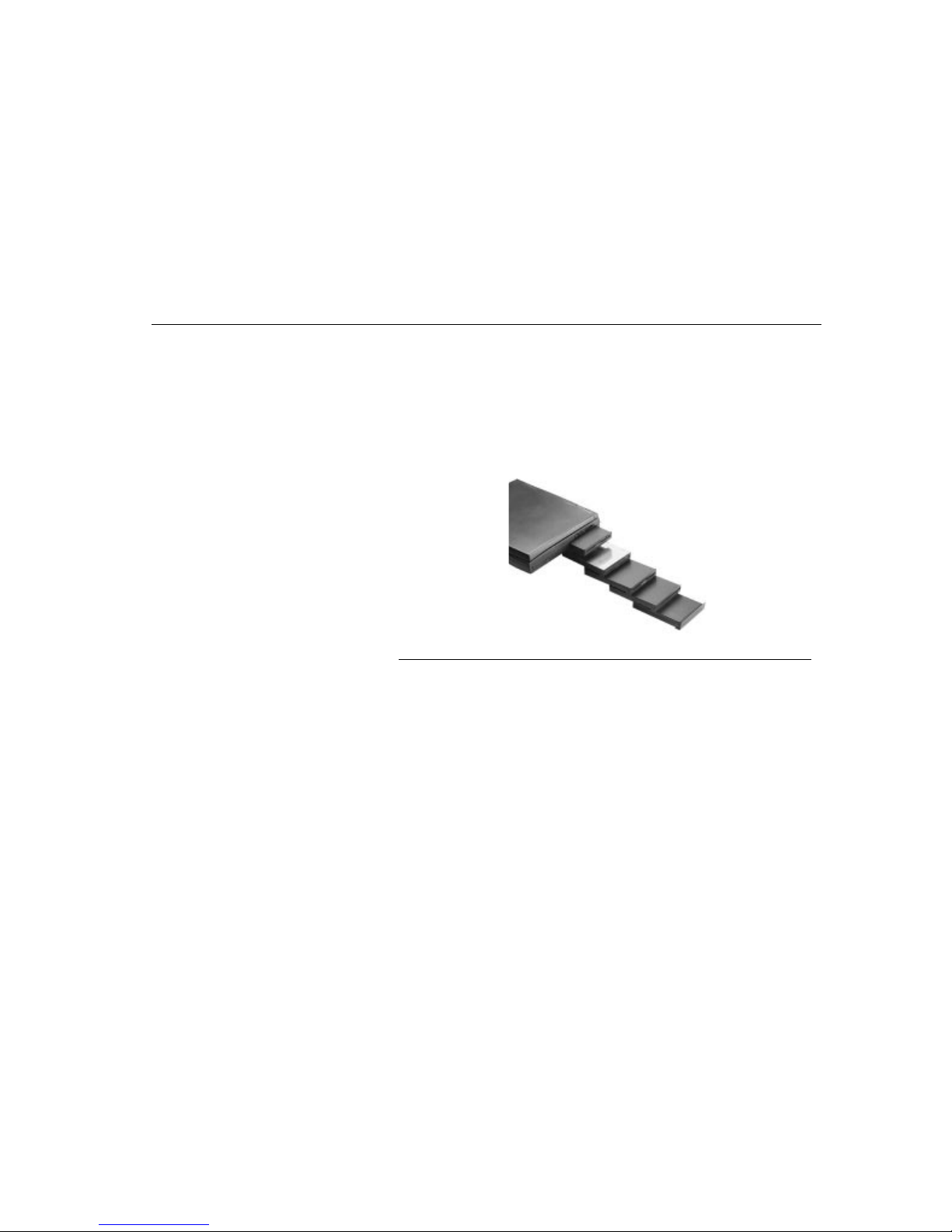
Data Storage and Retrieval
Chapter Four - Data Storage
53
Chapter Four - Data
Storage
Data storage and retrieval are two of the most fundamental tasks you will perform
when working with your computer.
Data Storage and Retrieval
The TransPort NX is equipped with a 3.5" floppy disk drive (FDD) and a hard disk
drive (HDD). The hard disk drive is removable, allowing for easy upgrades.
Sometimes referred to as “SmartBays”, these two types of drives and their
associated circuitry comprise your computer’s main data storage and retrieval
system.
Figure 22. SmartBay s
Floppy Disk Drive
Your TransPort NX features a removable high-density 3.5-inch floppy disk drive,
or an optional LS-120 (120MB) drive, module. The floppy disk drive interfaces with
the rest of the TransPort NX’s system via a disk drive controller. The disk drive
controller is an integral part of the computer’s main board architecture. The disk
drive transfers data between the diskette and memory as requested by the
system. The floppy disk drive is designated drive A: by the operating system.
The floppy diskette is the most widely used data storage medium for transferring
data from one PC to another. The coated mylar disk is enclosed in a plastic case
that protects the disk from damage caused by scratches, bending, and dust.
Using Floppy Diskettes
1. Insert the diskette into the drive with the label side up. Most diskettes have an
arrow to indicate which end goes in first.
2. Slide the diskette all the way in until the Diskette Eject button pops out.
3. To eject the diskette, push the Diskette Eject button until the diskette pops out.
Page 54

Data Storage and Retrieval
Chapter Four - Data Storage
54
When the FDD is being accessed, a green LED below the FDD door will
illuminate. A read/write head can carry out four basic operations as prescribed by
the disk operating system (Windows 95):
• Read data currently stored on the diskette
• Write new data to the diskette
• Erase data from the diskette
• Format a diskette
Your computer’s floppy disk drive accepts 720KB double-density (2DD) diskettes
or 1.2MB and 1.44MB high-density (2HD) diskettes. These diskettes are
sometimes labeled by the manufacturer as double density 1.0MB and highdensity 2.0MB diskettes.
These labels, however, indicate the unformatted capacities of the diskettes. The
TransPort NX FDD also supports a 1.2MB format in accordance with NEC PC
compatibility.
Removing the Floppy Disk Drive
The floppy disk drive is removable and swappable with other modules to give you
versatility while minimizing weight and size. To remove the floppy disk drive:
1. Save your work and turn off the computer.
2. Turn the TransPort NX over so that the rear ports are facing you.
3. Slide the FDD release latch toward the outside of the TransPort NX.
Figure 23. Removing the FDD
6HFXULW\
6FUHZ
5HOHDVH
/DWFK IRU
)'' %D\
Page 55

Data Storage and Retrieval
Chapter Four - Data Storage
55
4. Pull on the FDD finger grip to slide the FDD module out of the bay.
5. To insert the FDD module, slide the module into the drive bay so that it mates
with its connector. You will hear the release latch click shut.
W
ARNING
:
Never turn off or reset the TransPort NX while the FDD LED is on. Always
store your diskettes in a dry, clean container, to protect them from the
environment and magnetic fields.
Removable Hard Disk Drive Module
A hard disk, like a floppy diskette, magnetically stores data and retains that data
when the computer is turned off. Hard disk drives have higher capacities and
operate at much faster speeds than floppy disk drives.
Your TransPort NX comes equipped with a hard disk drive already installed and
prepared for operation. Your computer’s hard disk drive is an integrated drive
electronics drive, commonly referred to as an IDE drive, with a form factor of 2.5
inches. IDE drives have become an industry standard for PC hard drives because
they provide a reliable, fast, and cost-effective mass storage solution. The
formatted capacity of the TransPort NX’s HDD is 1.44GB or above.
Disk Caching
A disk cache is used to increase hard disk performance. It sets aside a portion of
the computer’s system memory where frequently used data from the hard disk is
temporarily stored. Because typical memory access time is several thousand
times faster than disk access time, a disk cache can yield a phenomenal increase
in your computer’s overall performance.
The SMARTDRV.EXE program included with MS-DOS is an example of a
program that can be used to implement a disk cache. This program allows you to
specify the amount of memory to be used as a disk cache. Refer to a DOS manual
for instructions on the SMARTDRV.EXE program. Windows 95, 98 and NT 4.0
have a built in cache utility.
N
OTE
:
If a program’s documentation specifies to disable a memory cache, it’s not
referring to a disk cache program like SMARTDRV.EXE. Memory cache is
different from a disk cache. A disk cache is used to speed up disk access,
whereas a memory cache is normally used to speed up access to DRAM.
Page 56
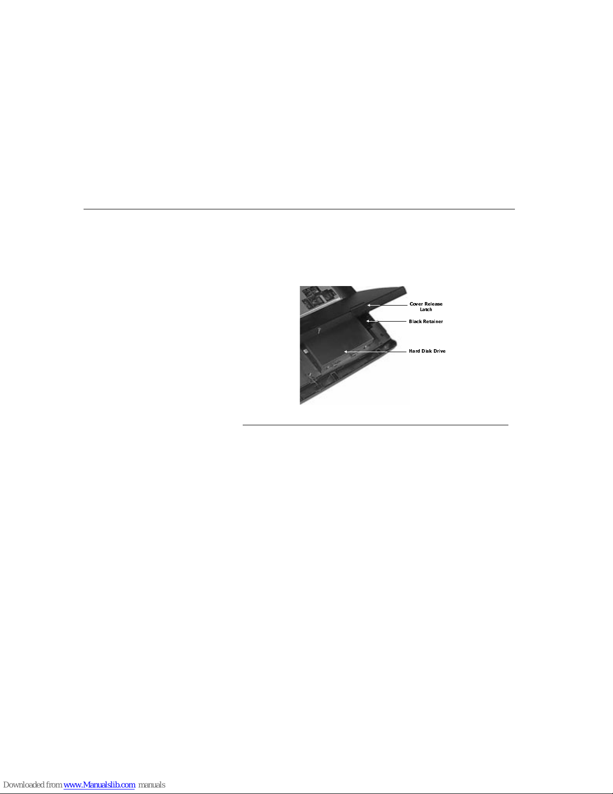
Data Storage and Retrieval
Chapter Four - Data Storage
56
Removing and Replacing the HDD
The TransPort NX’s hard disk is easily removed and replaced to allow easy
upgrades. To remove the hard disk drive:
1. Lift upward on the front two latches on the palmrest; slide back the palm rest
and then lift it up.
2. Lift the black retainer up on the right side of the hard drive.
3. Slide the hard drive slowly to the right to remove.
Figure 24. Removing the HDD
4. Installation is the reverse of removal.
CD-ROM
The TransPort NX comes with a built-in CD-ROM drive module. The CD-ROM
drive employs sophisticated laser and drive technology, yet requires very little
maintenance. Use the CD-ROM drive to run the latest multimedia CD titles
providing a new educational and entertainment dimension to your personal
computing experience.
The CD-ROM module can be swapped with a Digital Versatile Disk (DVD)
module, or a second HDD. DVD discs are the same diameter as a CD-ROM, but
can be recorded on both sides. Each side has a capacity of 4.7GB making each
DVD equivalent to 14 CD-ROMs if both sides are used. DVD players are
compatible with audio CDs, CD-ROMs, CD-I discs and video CDs, but not firstgeneration CD-ROM disks. TransPort NX does not allow DVD output to a
television. Second HDDs allow further expansion and versatility for your
TransPort NX, allowing you to store large multimedia files.
&RYHU 5 HOHDVH
/DWFK
+DUG 'LVN 'ULYH
%ODFN 5HWDLQHU
Page 57
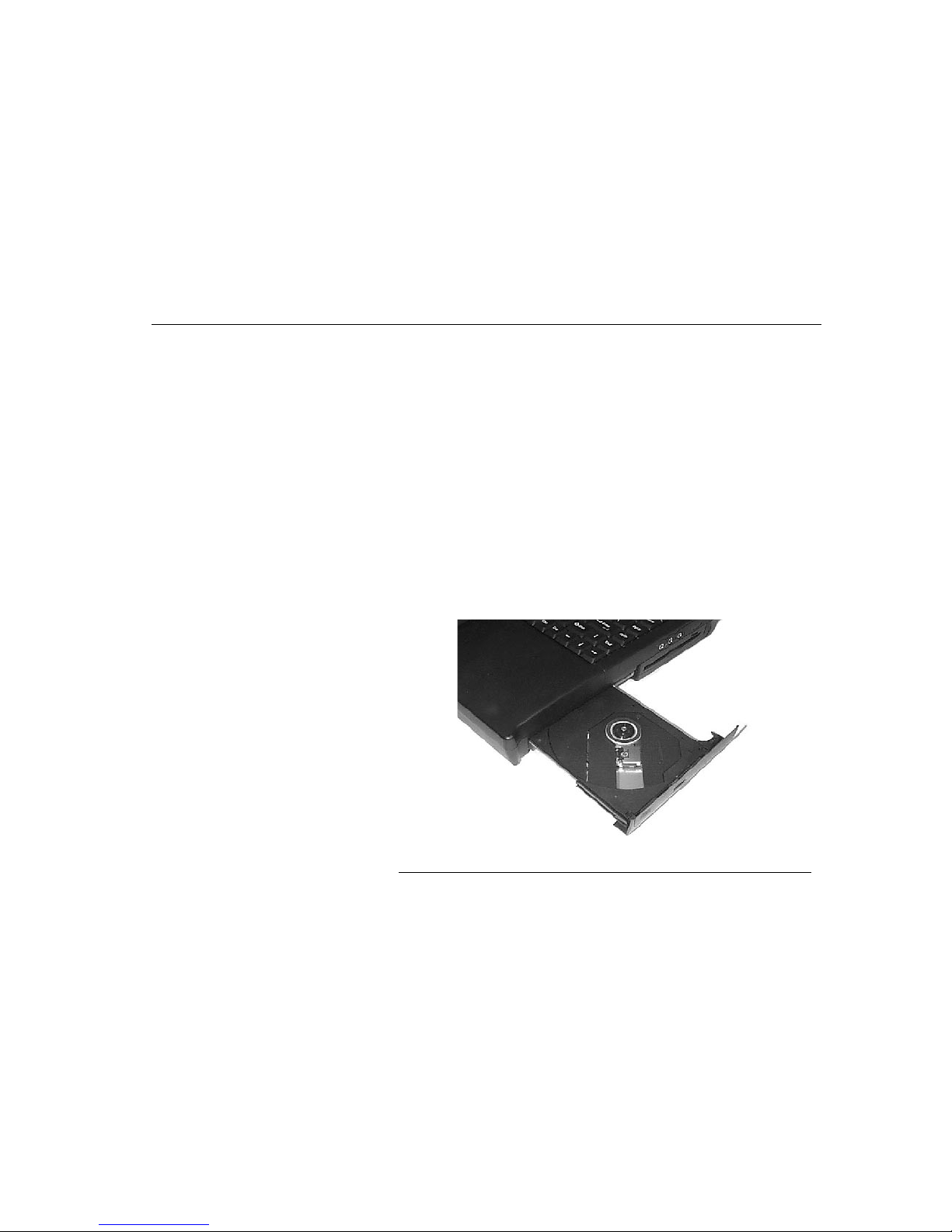
Data Storage and Retrieval
Chapter Four - Data Storage
57
CD-ROM Features
The features of the CD-ROM include:
• Audio play feature to play music CDs
• Front panel load/unload button
• 640 MB capacity
• MSCDEX compatible
• Supports CD-DA, CD-ROM mode 1 and mode 2
• Multi-Session Photo CD, CD-I/Video CD (ps.)
• Low power consumption
• 12.7mm height
Removing the CD-ROM Drive
The CD-ROM drive is removable and swappable with other modules to give you
versatility while minimizing weight and size. To remove the CD-ROM drive:
1. Save your work and turn off the computer.
2. Turn the TransPort NX over so that the rear ports are facing you.
3. Slide the CD-ROM release latch, holding it in place.
4. Pull on the CD-ROM finger grip to slide the CD-ROM module out of the bay.
Figure 25. Removing the CD-ROM
Page 58

Data Storage and Retrieval
Chapter Four - Data Storage
58
Installing the CD-ROM Drive
To insert the CD-ROM module, slide the module into the drive bay so that it mates
with its connector. You will hear the release latch click shut.
Loading a Disc
To play a CD disc, follow the instructions listed below.
1. Push the CD-ROM Eject button on the CD drive door, found on the front of the
computer. Gently pull the tray all the way out.
2. Carefully lift the CD-ROM by the edges and make sure the shiny surface is
face down (the side with no writing on it).
3. Carefully insert the CD-ROM onto the tray. Push the CD-ROM down gently so
that it snaps onto the center ring. Push the tray back into the drive.
Removing a Disc
To remove a CD-ROM, do the following:
1. Check the LED display and make sure that the computer is not accessing the
CD-ROM drive.
2. Push the Eject button and pull the tray all the way out.
3. Carefully pick up the CD by the edges and – while pressing down on the center
ring – remove the CD-ROM from the tray. Push the tray into the computer until
it closes.
N
OTE
:
Do not insert any foreign objects into the disc tray. When not in use, keep the tray
closed to prevent dust or dirt from entering the drive unit. If you experience
difficulty when ejecting the CD disk tray, stretch a paper clip (or use a pin or a thin
metal rod) and insert it into the emergency eject hole located on the right side of
the front panel. The CD disk tray should eject immediately. This procedure can
also be used to remove a CD from the drive when the
TransPort NX
is powered
off.
Reading CDs
The CD-ROM drive is designated drive D by default. However, it’s treated as a
low-priority device by the system. For ex amp le, if you have othe r driv es inst all ed,
they take precedence over the CD-ROM. The CD-ROM will always surrender to
the designated next priority drive.
There are a variety of CD products on the market. They go by various names,
such as CD-I, CD-Title, Audio-CD or Video-CD. Before playing a CD, you should
determine what type of CD it is, and run a playback program capable of running
that type of CD.
Windows NT comes with a mini-application that will run different types of CDs. Try
it by clicking start, applications, multimedia and media player.
Page 59

Data Storage and Retrieval
Chapter Four - Data Storage
59
Multimedia Sound System
Use the TransPort NX’s built-in audio capabilities to take advantage of a wide
range of education and entertainment multimedia software.
The multimedia sound system features a sophisticated on-board digital audio
generator that produces realistic music and human voice sounds in 16-bit stereo.
The TransPort NX is equipped with two internal stereo speakers, a microphone,
and both input and output audio ports for external audio units. An external
microphone can be connected to the microphone jack. External speakers or
headphones can be connected to the TransPort NX’s audio-out jack. External
audio devices can be connected to the Line in jack. All audio features are software
controlled. The TransPort NX’s multimedia sound system includes the following
features:
• An ESS PCI chip set
• Supports Sound Blaster game compatibility
• Supports Windows Sound System compatibility
• Full Duplex operation
• Hardware and software master volume control
• 64-Voice Wavetable synthesizer with Directsound support
• Dynamic filtering reduces noise and distortion rate
• 16-bit digitized audio playback
• A built-in microphone for conveni ent re co rd ing
• Two built-in stereo speakers
• Digitized audio recording through the TransPort NX’s built-in microphone or
any external source
Page 60

60
Page 61

Powering Your Notebook Computer
Chapter Five - Power Management
61
Chapter Five - Power
Management
Powering Your Notebook
Computer
This section contains information on the TransPort NX’s power system, including
the AC adapter, the battery system, recharging the battery, and tips for conserving
battery power. Also included are detailed descriptions of power management and
each of the power modes.
The power system is comprised of two parts, the AC adapter and the battery
system. The AC adapter converts AC power from a wall outlet to the DC power
required by the computer. The battery pack is a set of lithium-ion (Li-Ion) or nickelmetal hydride (Ni-MH) batteries housed in a plastic shell. There is one pack
inserted in the battery housing of the computer.
Power Saving Modes
There are several modes in which the TransPort NX may enter, automatically or
manually, in order to conserve power.
Full On Mode
This is the normal operation mode, when the notebook has not entered any
suspend or power saving modes.
System Idle Mode
Reduces the CPU speed.
Press any key to resume system operation. Operation
will also resume upon any hard disk activity.
Power Mode How mode is activated How to reactivate
System Idle Transits automatically Press any key or
access HDD
Standby Mode Tran si ts aut om atic al ly after
specified timeout
Press the power button
Suspend Mode
(Suspend to Disk or
Suspend to RAM)
Transits autom atic al ly after
specified timeout
Press the power button
Hard Disk Spin Down Transits automatically Access HDD
TABLE 7. Power Saving Modes
Page 62

Power Saving Modes
Chapter Five - Power Management
62
Standby Mode
In addition to reducing the CPU speed, this mode puts peripheral components in
their lowest active states. These peripheral components include the hard disk, the
LCD screen and the screen backlight. The TransPort NX enters Standby mode
when the system remains idle for a specified amount of time. Press any key to
resume system operation.
There are two ways the TransPort NX may enter the standby mode:
• The Standby timer “times out”, automatically placing the computer in
Standby mode.
• The Power button is pressed once, briefly.
All CPU and peripheral activity must have ceased prior to entering the Standby.
VGA activity (like clock updates) does not prevent the notebook from entering the
standby mode.
When the notebook enters the Standby mode the following will occur:
• The Standby LED becomes illuminated.
• Both the HDD and VGA controller will enter Standby mode to save power.
• The internal clock in the CPU will stop.
There are four ways the notebook will resume from the Standby mode:
• Any system activity detected.
• Movement of the mouse (touchpad or external mouse) or any keystroke.
• RTC alarm ring.
• Modem ring from serial or Cardbus source.
Suspend To RAM
The system is defaulted to Suspend to RAM in the BIOS. To suspend the system
press the Power On button once quickly to put the system into suspend. The blue
power light will begin to blink.
To “wake” the computer out of Suspend mode, press the Power On button once.
The system may take up to a minute to be fully functional. The blue light will be
steadly illuminated during this process.
Two conditions will cause the notebook to enter the Suspend mode:
• The Suspend timer “times out,” automatically placing the computer in
Suspend mode.
• The Power button is pressed once, briefly.
Page 63

Power Saving Modes
Chapter Five - Power Management
63
When the notebook enters the Suspend mode the following will occur:
• The Standby LED will flash.
• Most devices are powered off, except the system DRAM refresh function
and SMI inputs watching for internal keystroke, RTC alarm or modem ring.
• VGA enters Suspend mode to keep the Video RAM refresh.
There are three ways the notebook will resume from the Suspend mode:
• Internal keystroke (Power on button is pressed).
• RTC alarm ring.
• Modem ring from serial or Cardbus source.
C
AUTION
:
If the system is left in DRAM Suspend mode long enough to consume all
battery power, then the Suspend indicator goes out and all unsaved data in
the computer’s memory is lost. The system cannot resume until the battery
is recharged or the TransPort NX is connected to AC power.
Suspend To Disk
The system is defaulted to Suspend to RAM. To change the default to Save to
Disk, reboot the system and and go into the BIOS. (See “About BIOS Setup” on
page 43 and “Power Menu” on page 50.)
Four conditions will cause the notebook to enter the Suspend mode:
• The Suspend Timer was timed out and the 0 Volt suspend condition is
matched.
• The Power button is pressed once, briefly.
• Low battery warning has been issued and the battery is going into Low
battery.
• If the temperature of the CPU should exceed the maximum allowed (this
setting is dependent upon the CPU).
Page 64

Batteries
Chapter Five - Power Management
64
A Suspend Example
The time out settings for Hard Disk Off, System Standby, and System Suspend
specify the amount of time the system must be inactive before the next power
management level is enabled. The following example demonstrates this function.
If the Hard Disk Time-out is set to 2 minutes, the Standby Time-out is set to 8
minutes, and Auto Suspend Time-out is set to 10 minutes, the following power
management events take place:
1. After two minutes of system inactivity the hard disk spins down.
2. After six additional minutes (a total of eight minutes of inactivity) the system
enters Standby.
3. After 10 additional minutes in the system Standby mode, the system suspends
to memory or disk.
After the system has suspended, operation can be resumed at the point in your
application where it was suspended.
The amount of time that the system remains suspended depends on the amount
of battery power remaining. Due to this limitation, you should always save your
data before the system suspends.
Hard Drive Spin Down
The hard driv e is always spinning when in use; a lso if left idle with the system in
Full On mode. When the system is left idle for a set amount of time the drive will
power down or stop spinning. This is a power savings feature set in BIOS as a
default.
Batteries
Your computer comes with a rechargeable battery pack so you can operate the
computer without an external power source. When the battery pack is fully
charged, you can operate the computer for approximately three to four hours
under the following conditions:
• The battery pack initially has a full charge.
• No peripheral devices are installed.
• The disk/CD-ROM drives run no more than 10 percent of the time.
C
AUTION
:
There is a danger of explosion if battery is incorrectly replaced. Replace
only with the same or equivalent type recommended by the manufacturer.
Dispose of used batteries according to the manufacturer’s instructions.
Page 65

Batteries
Chapter Five - Power Management
65
Battery Discharge
It is a good idea to occasionally discharge the battery pack fully to preserve its
operating performance. Repeatedly recharging the battery pack when it has not
discharged completely can decrease the capacity of the battery pack. In the
battery pack there is a GAS-GAUGE IC to record the charge/discharge status of
the battery.
Y ou can also extend the life of the battery pack by using the computer’s powersaving features.
1. Disconnect the AC adapter from the external power source, then from the
computer.
2. Turn on the computer.
3. Ignore the power failure signals (i.e., battery warning beeps).
4. When the battery is fully discharged (that is, when the computer goes off),
attach an external power source and fully recharge the battery. The battery
charge icon on the Status panel indicates when the battery is fully charged.
Recharging the Battery Pack
The installed battery pack charges automatically any time the computer is
connected to the AC adapter and an external power source. The Li-Ion battery
can be fully charged in about four hours when the computer is turned off.
N
OTE
:
It is a good idea to occasionally discharge the battery pack fully to preserve its
operating performance.
An incorrect report of the battery status may be shown due to lost data of the
GAS-GAUGE IC caused by battery over-discharge. One reason for the battery to
over-discharge may be that the battery has not been charged for a long time. If
this is the case, a learning cycle is recommended to correct this problem.
The learning cycle is listed as follows:
1. Turn off the TransPort NX and use the AC adapter to charge the computer’s
battery pack to full.
2. Fully discharge and recharge the battery pack as described on page 65.
3. Remove the battery pack and check the GAS-GAUGE IC. If the indicator
shows 100% capacity then the learning cycle is done. Otherwise repeat the
learning cycle.
4. If after you try the second time and still fail to get the battery pack to 100%
capacity, contact Micron Electronics.
Page 66
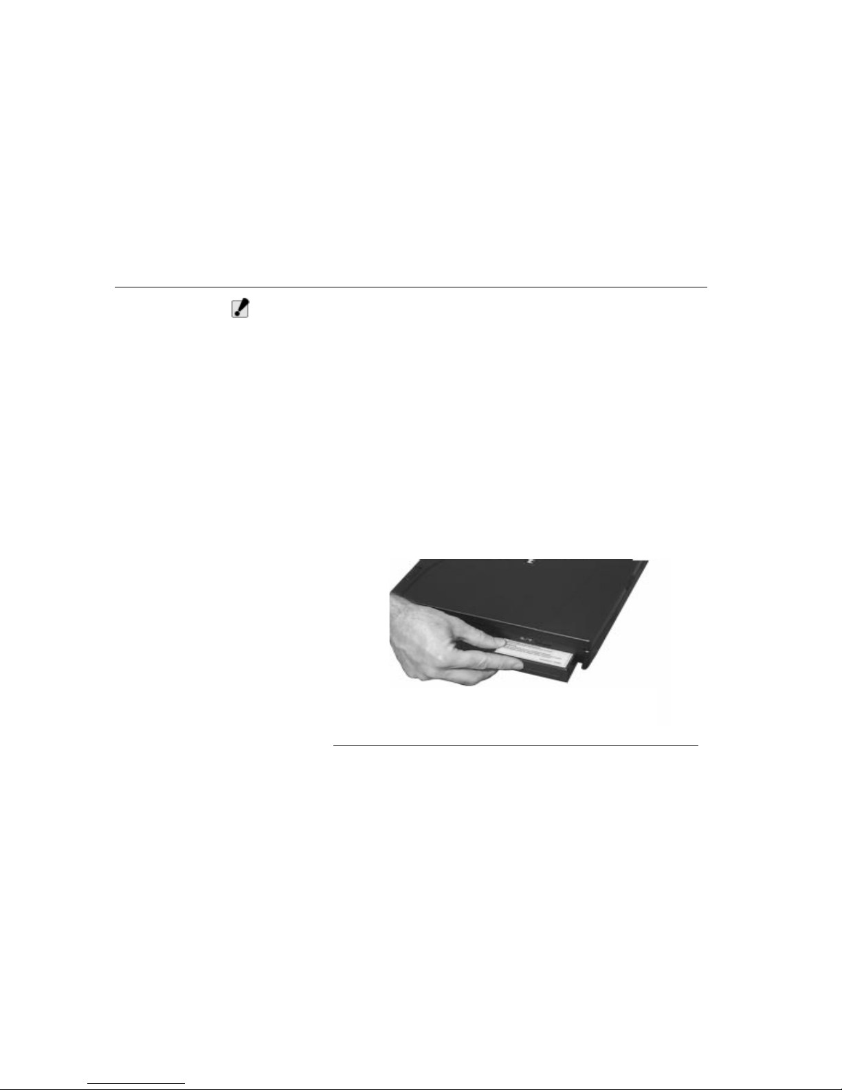
Batteries
Chapter Five - Power Management
66
C
AUTION
:
Only use batteries that are provided by Micron Electronics. All batteries are
not the same and therefore should not be treated as such. Using the wrong
battery could cause serious damage to your computer and yourself through
toxic emissions. Damage caused by a third party battery will not be covered
by the computer’s warranty.
Inserting the Battery Pack
The battery pack should already be inserted in your TransPort NX computer when
you unpack it. If it is not inserted:
1. Turn off the TransPort NX.
2. Open the battery bay door. Slide the battery release latch to the left.
3. Insert the battery into the empty compartment. It is designed so that it only fits
one way. It should easily click into place.
4. Close the battery compartment cover.
Removing the Battery Pack
To remove the battery pack:
1. Turn off the computer.
2. Open the battery bay door. Slide the battery release latch to the left.
3. Lift the battery finger grip and pull the battery from the bay.
Figure 26. Removing the Battery Pack
Page 67

Batteries
Chapter Five - Power Management
67
Battery Power System
The TransPort NX’s Li-Ion removable battery pack is found in the battery
compartment. A fully charged pack will provide approximately three to four hours
of battery life. The battery life can be extended by using the power management
features. The battery system implements the smart battery standard which allows
the battery to accurately report on the amount of usable time and charge
percentage left in the battery before recharging is required.
Additional battery packs are optional equipment and can be purchased
separately. Before using the computer on battery power for the first time, check
the battery status icon on the Windows Toolbar to make sure the battery is fully
charged. Charging the Li-Ion battery pack takes about 4 hours to charge, when
the system is not in use. If possible, always charge the battery completely.
Preparing the Battery Pack for Use
Before using the battery pack for the first time, the Smart Battery IC within the
battery pack should be calibrated in order to get accurate reporting of remaining
battery life status. To calibrate the battery pack follow the instructions below:
1. Insert the battery into the battery compartment and turn on the TransPort NX. If
the battery is completely without power go to the next step. Otherwise, let the
battery run down until the battery low warning beeps are heard. The system
will automatically enter
Suspend
mode.
2. Turn the TransPort NX off. Connect the AC adapter and let the battery fully
recharge. When the battery charge indicator turns off, the battery is fully
charged.
The battery pack is now calibrated properly. In general, using the battery until the
low battery warning indicator appears and fully recharges the battery each time
(full discharge/charge cycle) will ensure the accurate reporting of the battery
gauge status.
Battery Status
Windows 95 and Windows 98 have an applet in the
Control Panel
that will
display an icon in the Windows taskbar indicating when the TransPort NX is
running on battery power or is attached to the AC adapter. This applet also
displays a meter that indicates how much charge is remaining in the battery.
Page 68
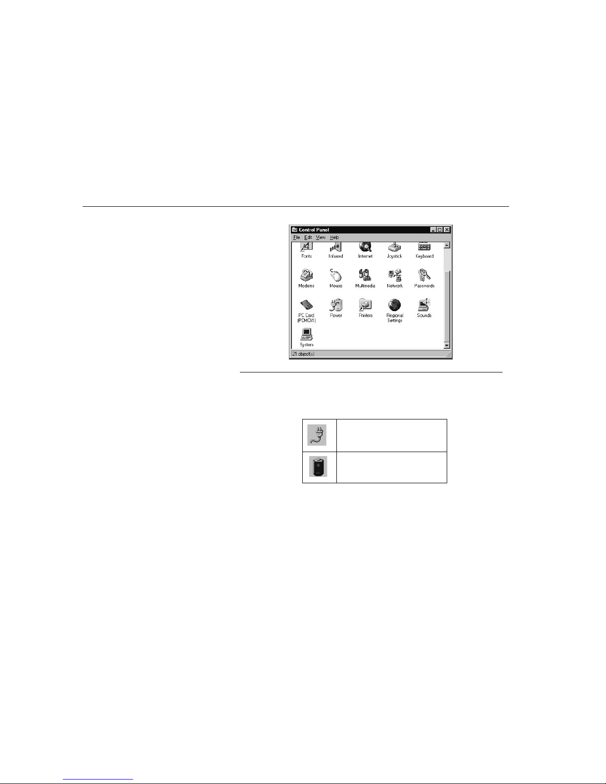
Batteries
Chapter Five - Power Management
68
1. To open this program click on Start, then Settings. Click Control Panel.
Figure 27. Control Panel
2. In the Control Panel, double click Power. The Power Properties screen will
appear.
3. Click the box next to Show Battery Meter on the taskbar to have the power
icons displayed on the Windows taskbar.
4. Double click the Battery icon to display the following screen:
This screen indicates how much battery charge remains. If the battery charge
drops below a certain voltage level, a beeping sound will prompt you to save your
work and turn off the computer, or connect the AC adapter.
When the AC plug is displayed, it
indicates that the AC adapter is
attached to the TransPort NX.
When the battery icon is displayed,
it indicates that the T ransPort NX is
running on battery power.
TABLE 8. Battery Icons
Page 69

AC Adapter
Chapter Five - Power Management
69
Battery Low Warning
When the pack initially reaches the Battery Low state approximately 10 ~ 15
minutes of the usable battery life is left. You will hear an audible beep signal every
1.5 seconds alerting you to the Battery Low status. When the battery power
reaches the Battery Low status the beeping sound will accelerate. Your battery
now has one to two minutes of battery charge remaining. You must save your
data or connect AC power immediately; otherwise, you may lose your data.
When there is only one minute of battery charge remaining, the TransPort NX will
suspend to the HDD (if a ZVHDD partition has been set) and power off. If a
ZVHDD partition has not been set the TransPort NX will suspend to DRAM. You
should connect AC power and resume to save your work.
Windows 95/98 has a smart battery function for changing the settings for the
battery warning signals. Please consult the Windows 95/98 help for details. To
extend battery power, we recommend that you make full use of the TransPort
NX’s built-in power saving features.
Small Battery for Real Time Clock
There is a small built-in battery pack that supplies power to the system in order to
maintain certain system information while the power is off. If the TransPort NX is
left without a power source for too long, this battery will be exhausted and system
information will be lost. Please avoid this condition by ensuring that the TransPort
NX never remains without a power source for more than ten days.
C
AUTION
:
Never remove the battery pack while the power is on as this may result in
data loss when the system loses power.
Power Management Habits
While operating the TransPort NX on battery power, it is important to develop
good power-saving habits to maximize battery life. Although the TransPort NX
provides automatic power-saving features that can be enabled, you can still
improve on them by keeping power conservation in mind.
AC Adapter
The AC Adapter’s primary function is to provide power to the TransPort NX. When
the adapter is connected to the computer, it provides power as long as it is
plugged into an electrical wall outlet. If the AC Adapter is not functioning properly,
please consult your dealer immediately for support.
Page 70

Screen Brightness
Chapter Five - Power Management
70
Conserve Battery with AC Adapter
The most obvious way to conserve battery power is to avoid using the battery
when there is an available AC power source. The AC Adapter is lightweight and
compact, so it is very convenient to bring along while traveling. By using the AC
adapter as much as possible, you can ensure you will have a charged battery
whenever you really need it.
Screen Bright ness
The brighter the LCD display screen is, the more power it requires. Avoid setting
the screen brightness level higher than necessary to extend the duration of
battery power.
APM Interface
In addition to the power saving features built into the resident BIOS System
Configuration Utility, your TransPort NX computer also supports the Advanced
Configuration and Power Interface (ACPI), an industry specification authored by
Microsoft, Intel and Toshiba to enable demand-based power consumption. It
allows for collection of power consumption information from the entire computer
and gives complete device activity control to the Operating System, enabling it to
provide power to only those devices that need it - when they need it. The functions
of ACPI can:
• Lower processor clock speed when it determines that running applications
do not need the CPU to run at full speed
• Control motherboard and peripheral device power consumption by turning
on devices only when needed
• Regulate applications’ activity through a continually updated demand
analysis of running software
• Calculate and provide accurate battery life readings through use of the
Smart Battery System
• Change its power management policies depending on battery life
With ACPI constantly monitoring all system activity, accounting for the TransPort
NX’s power consumption, and controlling all power-saving features, you will
realize significant additional power savings.
Page 71
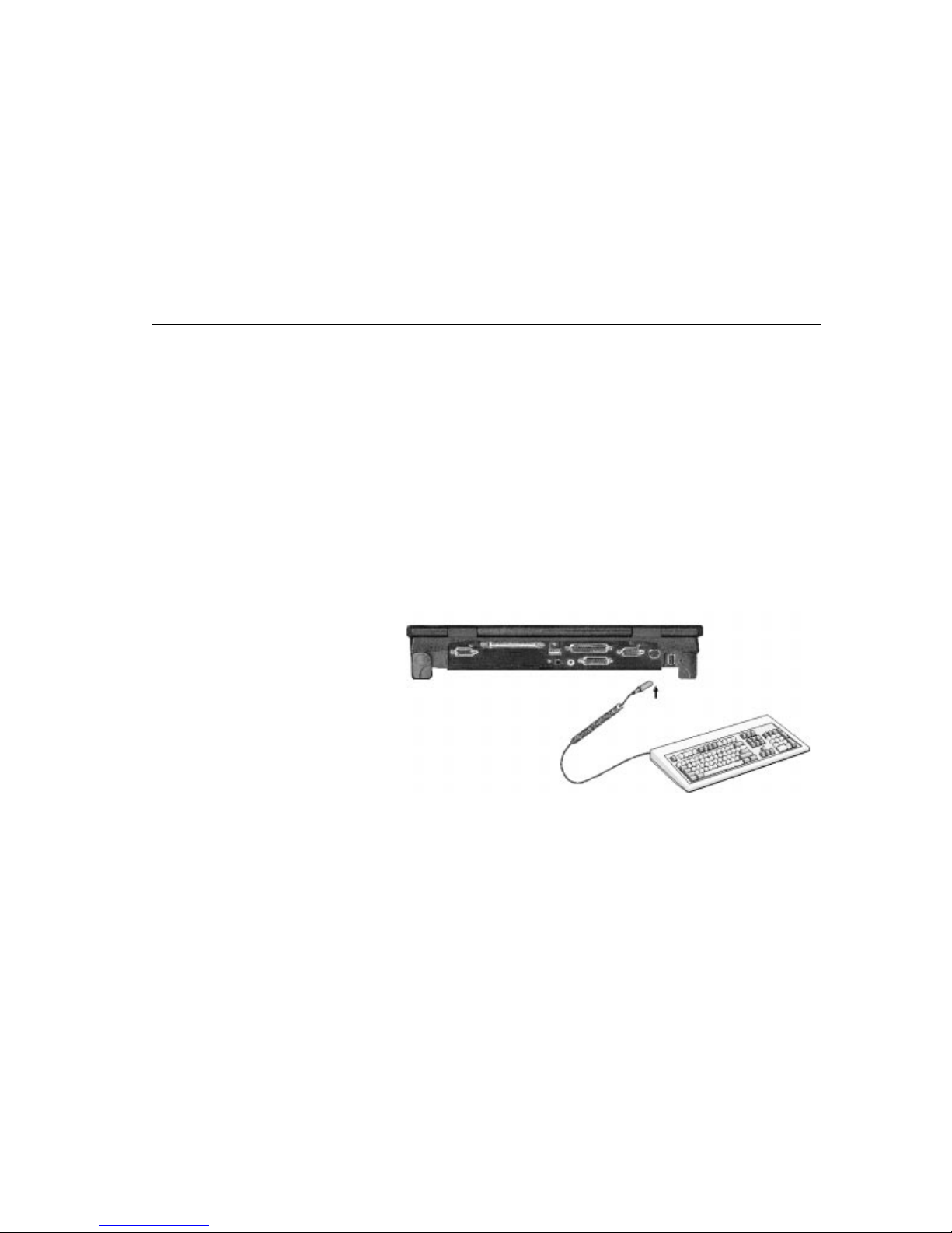
External Devices
Chapter Six - Optional Accessories
71
Chapter Six Optional
Accessories
To expand your computing capabilities, you can add a variety of external devices
to your computer. You may, for example, want to add a mouse, modem, or a
printer. The computer is equipped with several interface ports, including an
enhanced parallel (printer) port, a serial port, and two USB ports. These are
provided as a means of connecting peripheral devices to the computer.
External Devices
You can use your TransPort NX computer with an optional external keyboard,
numeric keypad, or IBM PS/2 compatible mouse. The devices are hot pluggable.
You do not have to power down the TransPort NX to connect these devices.
External Keyboard
To connect an external keyboard to your computer:
1. Place the keyboard at the front of the computer or in another location
appropriate for typing.
2. Plug the keyboard cable connector into the PS/2 keyboard socket on the left
side of the computer.
3. Adjust the legs on the underside of the keyboard for a comfortable typing
angle.
Figure 28. Connecting an External Keyboard
Page 72
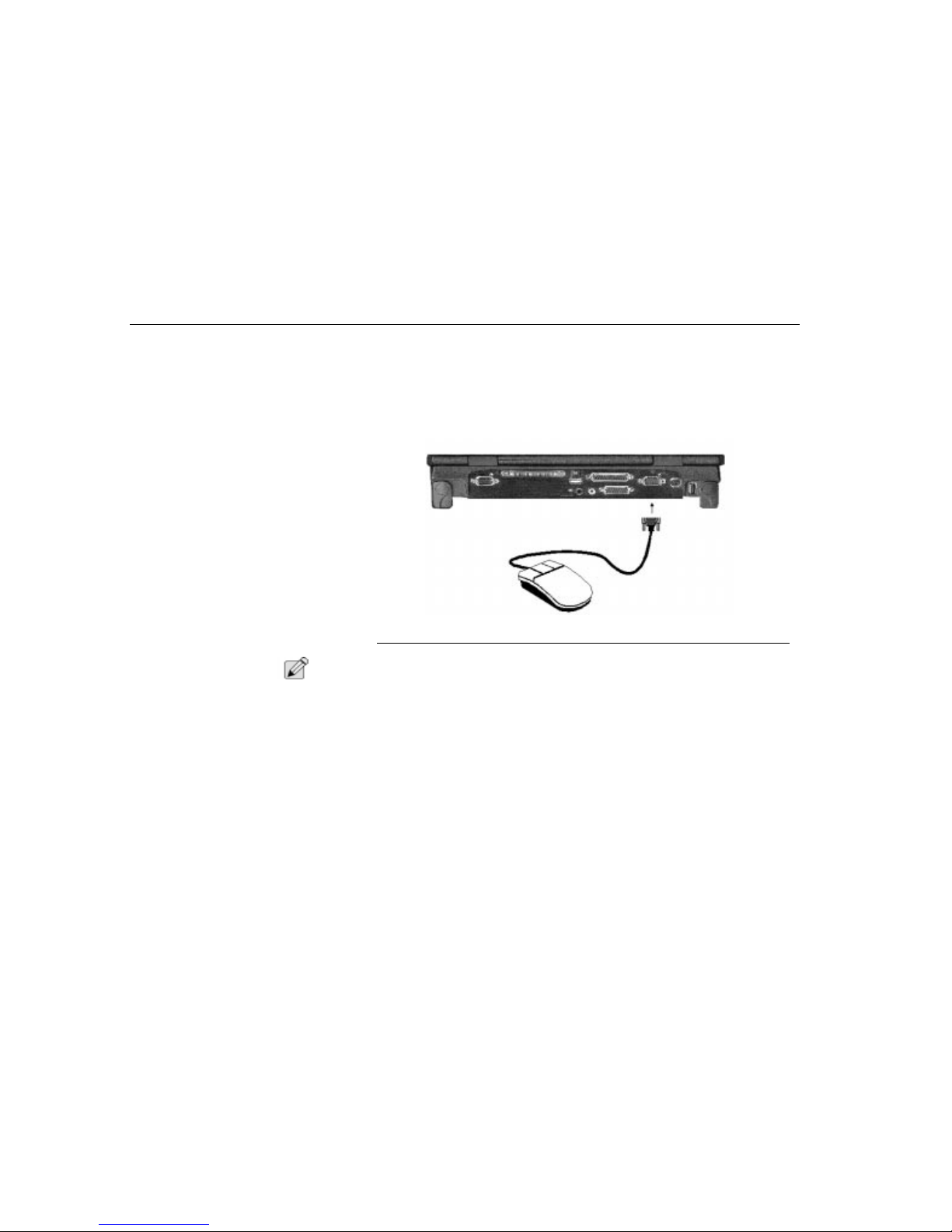
External Devices
Chapter Six - Optional Accessories
72
External Mouse
To connect a PS/2 compatible mouse to your computer:
1. Plug the PS/2 mini-din connector into the keyboard/mouse socket on the left of
the computer. The mouse works immediately after being plugged in.
Additionally it can be used with the internal touch pad or pointing stick.
2. After you connect a peripheral device to the serial port, secure the two small
screws on the connector.
Figure 29. Connecting an External Mouse
N
OTE
:
You cannot use the touch pad and a serial mouse at the same time. In order to
use a serial mouse, first disable the touch pad, then enable and configure the
mouse as specified by the manufacturer. Please refer to the ”Hot Key Controls”
section in ”Chapter Two - System Features” , and the Internal PS/2 device section
in ”Chapter Three - Running BIOS Setup.” If you wish to run a PS/2 keyboard and
mouse at the same time, please contact Micron for a splitter cable.
External Monitor
You can connect a TV monitor to the TransPort NX’s S-Video port and view the
TransPort NX’s video output. The TV Out port accommodates a Mini DIN type
connector. To connect the external monitor:
1. Plug the monitor’s power cable into a wall outlet.
2. Before you turn on the monitor, turn on your computer and use the System
Setup to designate the screen(s) that you want to use.
Page 73
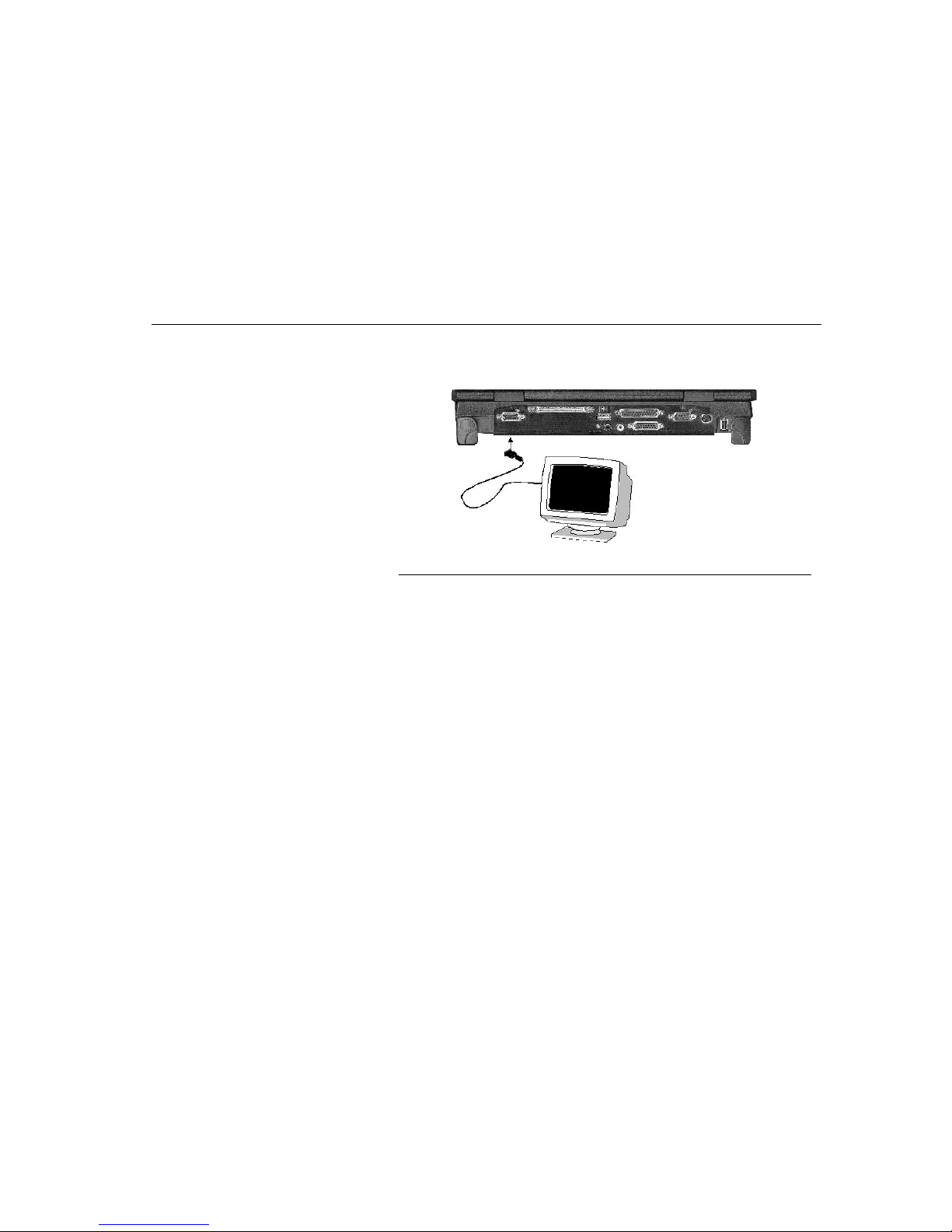
Serial Devices
Chapter Six - Optional Accessories
73
3. Turn on the monitor and adjust the monitor stand so that you have a good
viewing angle of the screen.
Figure 30. Connecting an External Monitor
External Printer
Your TransPort NX computer is equipped with an enhanced bi-directional parallel
port. Use the parallel port to connect the computer to a printer or plotter. The
parallel port is the most widely used interface on personal computers because it
usually does not require setup commands or special configurations on either the
computer or the peripheral device. After you connect a peripheral device to a
parallel port, secure the two small screws on the connector.
Serial Devices
The rear panel of the TransPort NX computer has a standard RS-232C serial
interface port. Use the serial port to connect a peripheral device that can both
input data to the computer and receive data from the computer. Serial ports are
widely used on everything from mainframe computers to display terminals and
modems.
The serial port on the rear panel is designated COMA. The COM port designation
is a conventional way to tell your software which I/O (input/output) address to use
in order to send and receive data. These I/O addresses are defined by IBM in their
Technical Reference manuals, and are understood by all popular software
manufacturers.
Page 74

Audio Sources and Output Devices
Chapter Six - Optional Accessories
74
Audio Sources and Output
Devices
The built-in audio features of your TransPort NX let you record and play back
sound from a variety of sources. These features include:
• PCI stereo sound that supports Microsoft Windows, Microsoft Sound
System, and most programs that use the SoundBlaster Pro standard.
• The ability to perform real-time recording with compression and
decompression.
• Scalable sampling rate (from 4 to 48KHz) and compression ratios that give
complete control of record time to required storage ratio.
• 3-D positional audio DirectX™.
• Digitally controlled volume with muting.
• Auxiliary line-in and speaker line-out for maximum flexibility.
• Built-in microphone and speaker to enhance portability.
To adjust the volume of your internal speakers or speakers attached to the stereo
speaker port, use the volume controls found in your application or in the Windows
Volume Control accessory.
Your computer comes with several software utilities and programs already
installed. Among these is a group of programs which let you control the
computer’s various audio capabilities.
Universal Serial Bus
The Universal Serial Bus (USB) has a total bandwidth of 12Mb per second. Up to
127 devices can be attached in a daisy chain fashion. For example, a USB
keyboard or monitor could host several ports for additional devices. It is expected
to be used for devices such as the mouse, keyboard, printer and scanner.
USB Devices
You may optionally purchase a USB (Universal Serial Bus) device for your
TransPort NX computer. USB devices such as mice, keyboards, and monitors are
becoming more widespread throughout the computer industry.
The USB bus has a total bandwidth of 12Mb per second. Up to 127 devices can
be attached in a daisy chain fashion. For example, a USB keyboard or monitor
could host several ports for additional devices. It is expected to be used for
devices such as the mouse, keyboard, printer and scanner.
LS-120 Drive
LS-120 is also referred to as the next generation FDD since it’s backward
compatible (you can read all your old 3.5" FDD’s in the LS-120) and you can save
120MB on a special LS-120 diskette. The speed is five times faster than the FDD.
Page 75
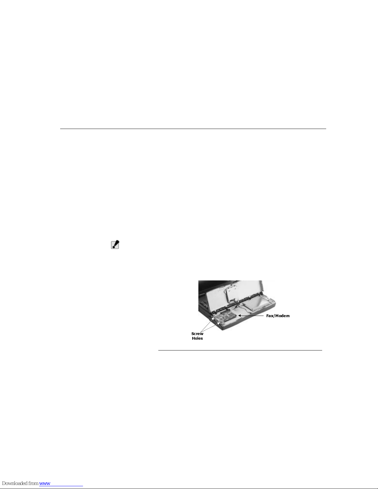
Zip Drive
Chapter Six - Optional Accessories
75
Zip Drive
ZIP drives are very popular in desktop computers as well as external units for
older notebooks. Your notebook can have this drive built-in. The ZIP drive is 20
times faster than a FDD and can store 100 to 250MB on a ZIP diskette. Note that
floppy diskettes cannot be read in the ZIP drive. Contact your notebook dealer if
you would like a ZIP drive for your TransPort NX.
Optional Fax/Modem
This 56K/33.6Kbps FAX/DATA modem connects your computer to all popular
high-speed modems available today. Your new modem is compatible with
systems for simplified installation and configuration. This section describes the
hardware installation procedures for your new modem. Additional information on
AT commands and S-registers is provided so that your system can be customized
for your particular operating environment. See “Appendix D - Fax/Modem
Information” on page 143.
If your TransPort NX does not have a pre-installed fax/modem and you wish to
install one, you need only follow these simple instructions:
1. Open the palmrest of the TransPort NX. On the left will be an empty space for
the fax/modem.
W
ARNING
:
Always disconnect the faxmodem from the telephone system when
installing or when the palm rest is open.
2. Make sure the notebook is turned off and remove battery and power cords.
3. Insert the fax/modem with the connector facing the connector in the TransPort
NX.
Figure 31. Installing a Fax/Modem
6FUHZ
+ROHV
)D[0RGHP
Page 76
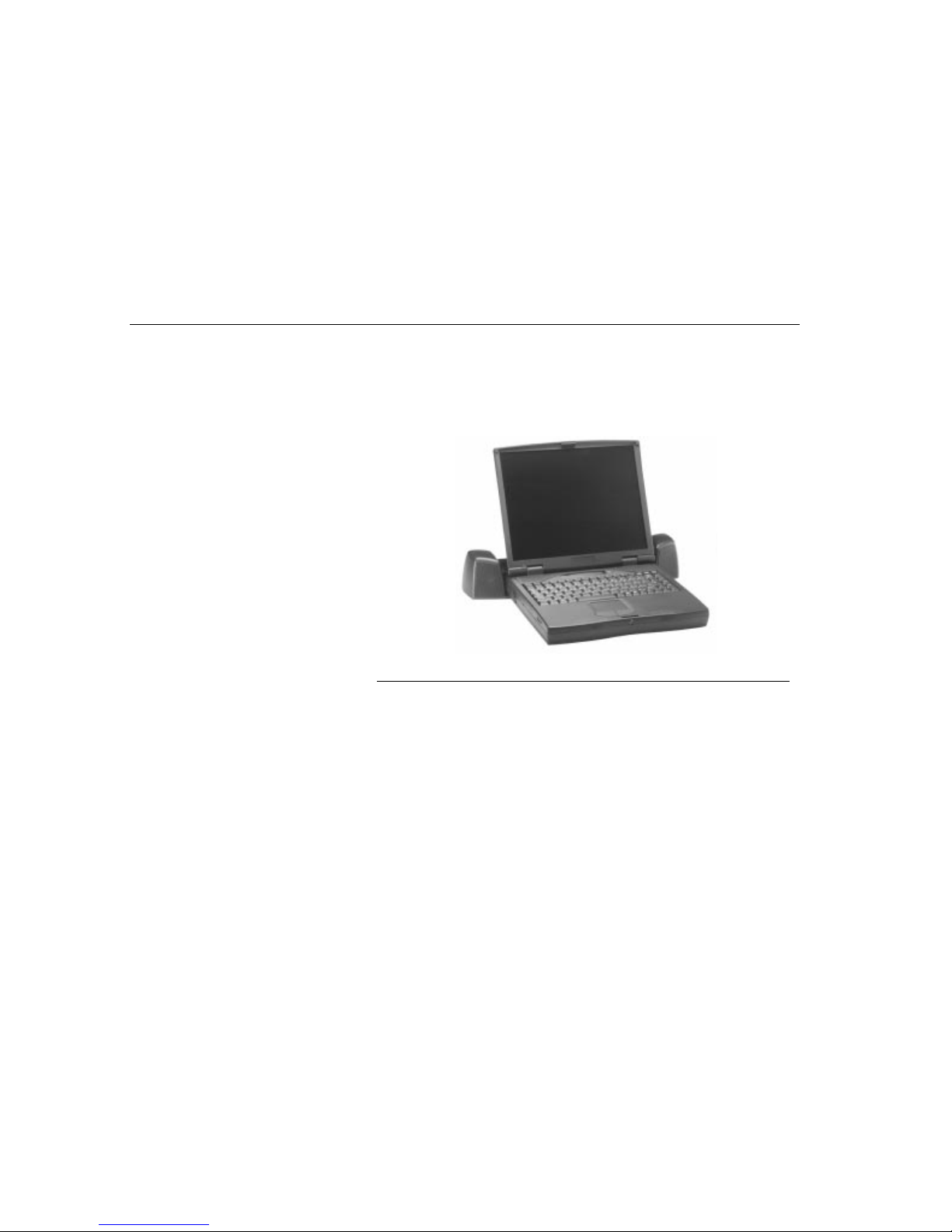
Optional Port Replicator
Chapter Six - Optional Accessories
76
4.
Attach the metal cover to protect the fax/modem. It should line up with the
screw holes against the left side.
5.
Close the palmrest and reinsert battery and power cords.
Optional Port Replicator
The port replicator is designed to give your notebook computer the expendability
and connectivity of a desktop computer, without sacrificing convenience.
Figure 32. TransPort NX “docked” with Port Replicator
Operating Environment
To enhance its reliability, this product must operate as intended in the face of
typical environment conditions. Our major task is to prevent equipment damage
and to minimize any malfunctions.
• Do not leave in a place where foreign matter or moisture may enter the
system.
• Do not subject to shock or vibration.
• Avoid exposer to excessive heat or direct sunlight.
• Avoid exposer to strong magnetic fields.
Page 77
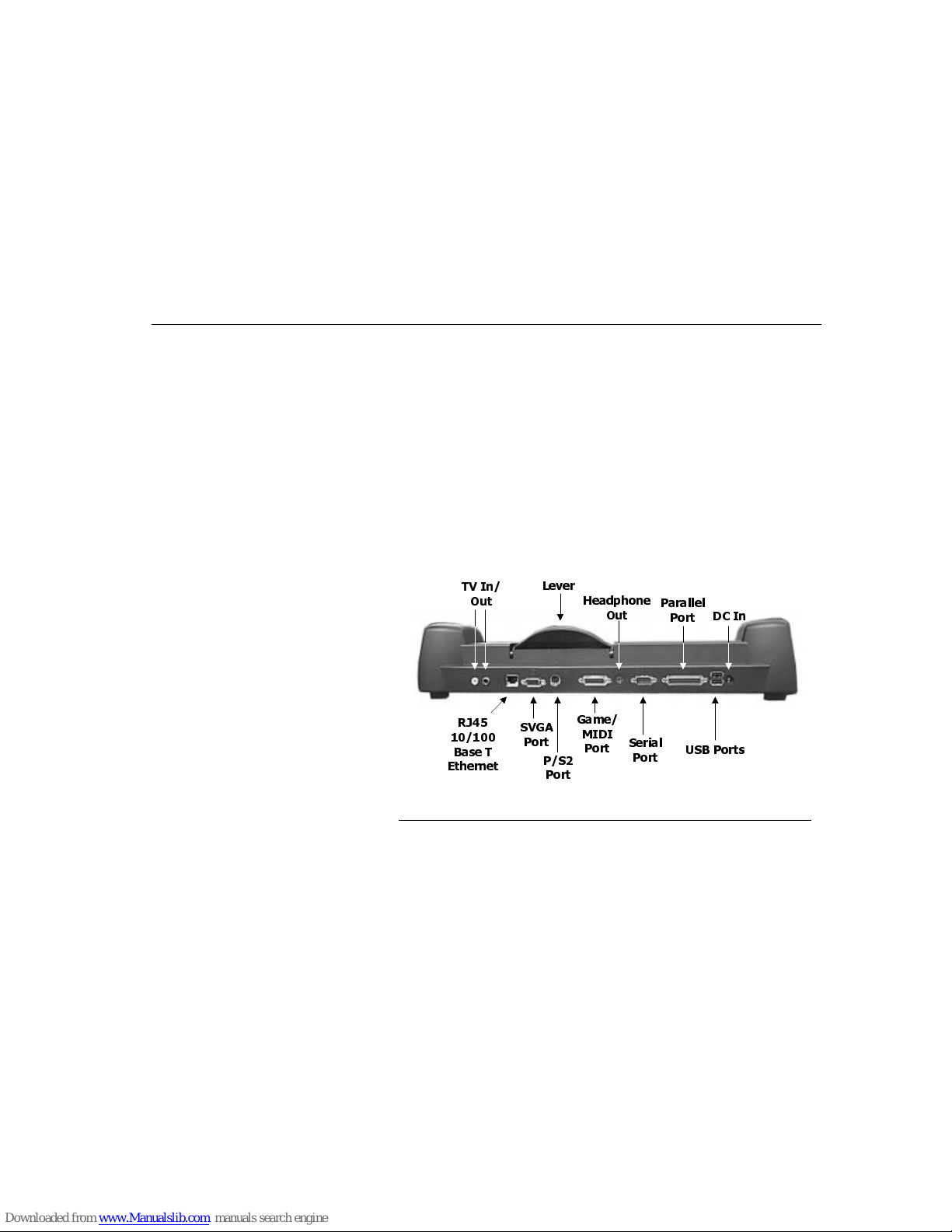
Optional Port Replicator
Chapter Six - Optional Accessories
77
Features
When the notebook compute r is connected to the por t replica tor, the system has
the following features:
•
One Serial Port
•
One Parallel Port
•
One VGA Port
•
One PS/2
•
Two USB Connectors
•
One Game/MIDI Port
•
One DC-IN Connector
•
One TV In Connector
•
One TV Out Connector
•
Headphone out jack
•
One 10/100 Base T Ethernet connector
Figure 33. Port Replicator Features
79 ,Q
2XW
/HYHU
+HDGSKRQH
2XW
3DUDOOHO
3RUW
'& ,Q
5-
%DVH 7
(WKHUQHW
69*$
3RUW
*DPH
0,',
3RUW
6HULDO
3RUW
86% 3RUWV
36
3RUW
Page 78
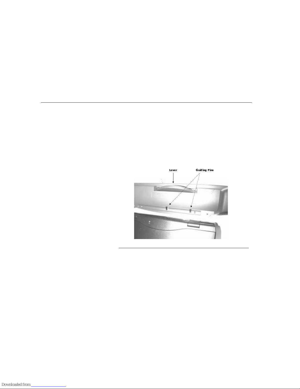
Optional Port Replicator
Chapter Six - Optional Accessories
78
Connecting The Port Replicator
The notebook computer connects to the 204-pin connector on the front of the port
replicator.
1. Turn off the notebook computer power.
2. Disconnect all peripheral accessories.
3. Plug the DC adapter into the DC IN connector on the back of the port
replicator.
4. Place the port replicator in a location that is convenient for using the computer.
5. From your notebook’s rear panel, open the small door covering the port
replicator connector and fold it down.
6.
Locate the two position guides (holes) at the bottom edge of the notebook
computer and align them with the pegs of the port replicator.
Figure 34. Connecting the Port Replicator
7.
Once both of them are aligned properly, press the notebook computer
downward to fully attach it to the port replicator.
8.
Push down on the lever arm to plug the 204-pin port replicator connector into
the computer connector.
Cold Dock
Press the Power/Suspend/Resume button to turn on the computer.
*XLGLQJ 3LQV/HYHU
Page 79
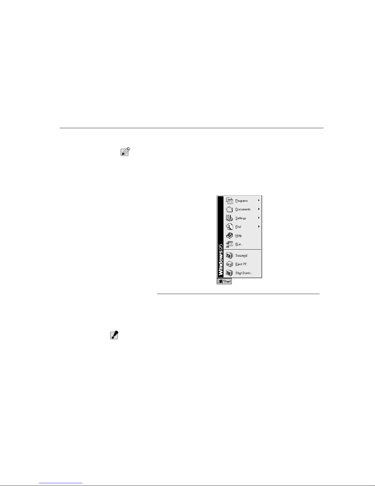
Optional Port Replicator
Chapter Six - Optional Accessories
79
Disconnecting the Port Replicator
To remove the computer from the port replicator pull up the lever arm up to
release the TransPort NX.
N
OTE
:
Before doing this, be sure that the notebook and port replicator internal
components are completely disconnected.
Disconnectin
g by
Software Application
PROCEDURE ONE:
Click on the
Start
button and select the
Eject PC
option to disconnect the two
units. The notebook computer will enter the
Suspend Mode
. Pull up the Lever
Arm to totally disconnect the two units.
Figure 35. Start Menu
PROCEDURE TWO:
Press the [FN]+[F10] buttons to enter
Suspend Mode
. Pull up the Lever Arm to
totally disconnect the two units.
W
ARNING
:
Do not detach the notebook computer and port replicator by force or when
the notebook computer is still running any applications.
Page 80

DVD Installation
Chapter Six - Optional Accessories
80
Manually Disconnecting the Port
Replicator
After the internal components are completely disconnected, you are now ready to
separate the notebook computer and port replicator manually by following the
steps below:
1. Pull the lever arm up to completely separate the notebook computer and the
port replicator.
2. Lift the notebook computer up and away from the guiding bars of the port
replicator.
DVD Installation
The following section will help you setup and utilize your new DVD hardware.
Please follow these instructions carefully.
N
OTE
:
If you purchased your TransPort NX with DVD, all this has already been setup and
configured for you.
For best DVD performance we recommend that you disable all Power
Management features in the BIOS and Operating System.
W
ARNING
:
Using the RCA-video out function with the DVD drive to a television is not
recommended and will not be supported. You may experience degraded
video display quality on the television in this mode.
Removing the CD-ROM
1. Remove the CD-ROM drive from the bottom of your TransPort NX by sliding
the small tab on the bottom of the notebook, and gently pull out the DVD-ROM.
For more detailed instructions see “Removing the CD-ROM Drive” on page 57.
2. Insert the DVD-ROM drive into your TransPort NX where the CD-ROM drive
just came out of; open the LCD assembly and power on your TransPort NX.
3. Once Windows 95/98 has loaded, insert your Microns Electronics MCRC CD
into the DVD-ROM drive, select the DVD icon, and follow all the instructions
carefully.
W
ARNING
:
Using the RCA-video out function with the DVD drive to a television is not
recommended and will not be supported. You may experience degraded
video display quality on the television in this mode.
Page 81

MRestore CD-ROM
Chapter Seven - Software Utilities
81
Chapter Seven Software Utilities
MRestore CD-ROM
Included with your notebook computer is a CD-ROM titled MRestore. This CD is
only functional with Micron systems with an approved Micron BIOS.
Include on this CD-ROM are the following:
• The MCRC (Micron Customer Resource Center)
• Drivers (with instructions)
• A bootable option to access basic DOS functions, such as disk, format, etc.
• Drive Image / PartitionMagic / Drive Copy by PowerQuest
• Drive Image manual/user’s guide (more comprehensive than space allows
within this guide). These may or may not reflect the actual package that
you have; other applications may or may not be referenced.
MCRC (Micron Customer
Resource Center)
Use this CD to install drivers one at a time. It is a program that can only be used
from within Windows. This CD is needed to load any drivers that are not shipped
installed on the notebook as a default (such as DVD).
To use the MCRC, boot your system to its current operation system (such as
Windows 95/98), insert the MCRC CD and follow all instructions.
N
OTE
:
All drivers are pre-installed and tested by Micron. You will not have to run this CD
unless you are experiencing problems with your system or if you have recently
reinstalled the operation system.
PartitionMagic
Partition magic software is the provided to you so that you will have a method of
storing an image if no other means of storage are available. PartitionMagic can
only be run from a DOS level. The object of this software is to create partitions
and move them to an appropriate size for your needs. It also converts them with
different fat tables. This software becomes very useful when there is no location
for your storage. This is a brief overview of what is thoroughly contained in the
PDF located in the:\pqtools\userinfo directory on the CD.
Page 82

Drive Image 3.0
Chapter Seven - Software Utilities
82
Drive Image 3.0
Drive Image is for PC users who want a fast, complete solution for system
backups and recovery. With Drive Image you can easily create and store a
compressible image of the entire hard drive or individual partition on a Jaz, Zip,
secondary hard drive, or other removable media device. The image can then be
restored from the source and used for complete operating system, application and
data recovery.
N
OTE
:
Currently, Drive Image does not support creating image files directly on CD-R or
tape drives. You must first save image files to a supported source (hard drive, Zip
drive, etc.), then copy them to CD-R or tape. Drive Image can, however, directly
restore image files from CD-R.
Furthermore, image files can only be saved to devices that have a valid drive
letter. While Drive Image includes some device drivers (such as Zip), the user is
primarily responsible for loading the necessary drivers for their data storage
devices so that DOS can correctly assign drive letters (such as USB Zip or 2 Gig
JAZ).
Drive Image also includes other useful features such as the ability to resize
partitions, disk to disk copying for upgrading to a larger hard drive, and file
systems error and bad sector checking to prevent copying problems.
Drive Image supports the file systems of all versions of Windows 95/98, Windows
NT, Windows 3.x, DOS. And OS/2 including FAT32, FAT32X, NTFS, and HPFS
partition types. Because Drive Image understands the internal structure of these
file systems, partition resizing and fast SmartSector copying can occur.
Drive Image provides limited support for NetWare, Linux, UNIX and other partition
types. However, Drive Image copies such partitions sector by sector—and does
not resize them on the destination drive—making the image file creation and
restore process for these file systems more time consuming. Additionally, internal
disk location references are not modified on the destination drive. This may make
these partitions unbootable or otherwise inaccessible.
Drive Image is a DOS-based program that can be run from the hard drive in DOS
or MS-DOS mode or from a CD after booting DOS. Because multi-tasking
operating systems like Windows 95/98 and Windows NT operate with open files
on the hard drive, it is necessary to run Drive Image from DOS so that image files
are an exact copy of your hard drive. Only by running DOS is the hard drive
completely inactive with no open files.
Page 83
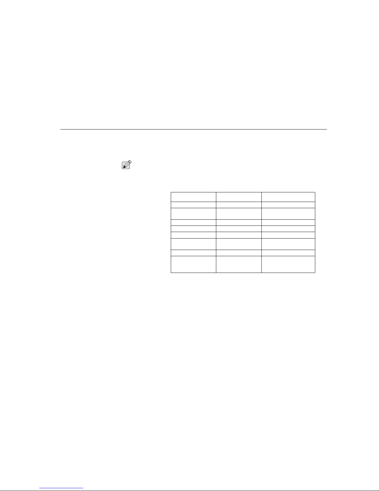
Drive Image 3.0
Chapter Seven - Software Utilities
83
Drive Image Professional
If you want the absolute fastest way to clone workstations, a Drive Image
Professional version is available for use on multiple PCs. For more information
contact Power Quest sales at 801-226-8977 or visit their web site at
http:www.powerquest.com. For upgrades only, call PowerGuest.
N
OTE
:
The complete manual for Drive Image is available on the MRestore CD, in the
PQtools\userinfo. folder.
Drive Image System Requirements
* For Windows NT and OS/2 users, Drive Image must be run from a bootable
floppy or CD.
Creating Image Files
If you create an image on one machine and you wish to restore the image on a
machine with a different configuration (for example, a different motherboard or
video card), the operating system may not boot correctly. Therefore, we
recommend imaging and restoring to identical hardware configurations.
Any discussion of hard-disk imagin g assumes that the software, including the
operating system, is being copied in accordance with the license agreement with
the software manufacturer.
Hardware/Software Minimum Recommended
Processor Intel 386SX Intel 486 above
RAM 8 MB (16MB required
for FAT 32 or NTFS)
32 MB (48 MB for FAT 32
partitions larger than 6 GB)
3.5 inch diskette drive None None
CD-ROM Any speed Any speed
Hard drive free space 5 MB 5 MB
Operating System Windows 3.x, 95/98,
NT, DOS 5.0, OS/2*
Windows 3.x, 95/98, NT,
DOS 5.0, OS/2*
Monitor VGA SVGA
Pointing Device No pointing device is
required to operate
Drive Image
Microsoft mouse (or
compatible pointing
device)
TABLE 9. Drive Image System Requirements
Page 84
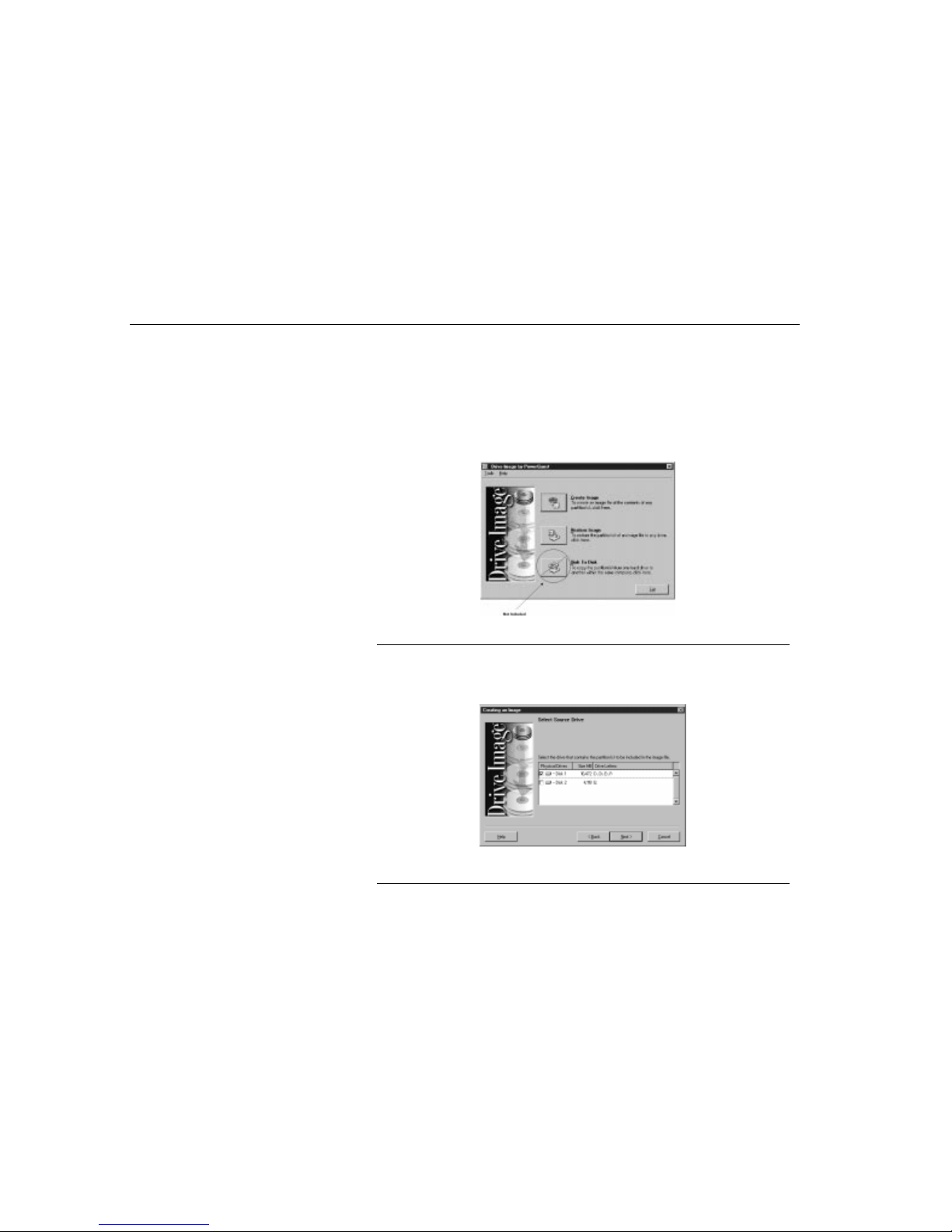
Drive Image 3.0
Chapter Seven - Software Utilities
84
1. You must disable virus protection in the BIOS before creating an image file. If
virus protection is enabled, Drive Image will hang after you click Finish.
2. Before running Drive Image, use a disk utility program such as ScanDisk or
Norton’s Disk Doctor to identify and repair any errors on your hard drive. NT
users should run CHKDSK /F.
3. You may also choose to run a disk defragmenting utility to further optimize
your hard drive.
4. At the Drive Image main screen, click Create Image.
Figure 36. Drive Image Main Screen
5. If you have more than one hard drive, select the drive that contains the
partitions you wish to include in the image file. A check appears to the left of
the selected drive.
Figure 37. Drive Image Select Source Screen
Page 85
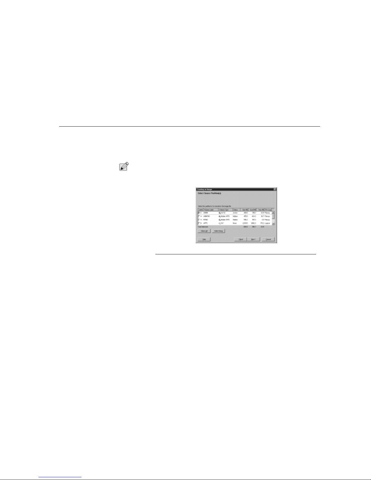
Drive Image 3.0
Chapter Seven - Software Utilities
85
6. Click Next. At any point prior to actual image file creation, you can click Back
to return to the previous step and change your settings.
7. Select the source drive partition you wish to include in the image file, or click
Select All to automatically select all partitions. A check appears to the left of
the selected partitions.
N
OTE
:
For best results in creating your image, you should include the Save to Disk
partition as well as the other partitions you wish to back up. Save to Disk is
necessary for Power Management features.
Figure 38. Drive Image Select Source Partitions Screen
To deselect partitions, click again on a partition or click Select None to deselect
all partitions at once. The Total Selected field displays the disk space for all
selected partitions, as well as the total used and free space within the partitions.
8. Click Next. Type the desired path and image filename in the Image File field,
for example: D:\MYIMAGE.PQI. Make sure there is no existing file with the
same name, unless you want the existing file to be overwritten.
9. You must save your image file to a partition, or other location that you are not
including in your image file. Drive Image uses.PQI as the default image
filename extension. You can also click Browse to browse the directory tree for
your desired path or filename. You can save your image file to any physical or
logical drive which has a drive letter. That includes floppy drives, secondary
Page 86
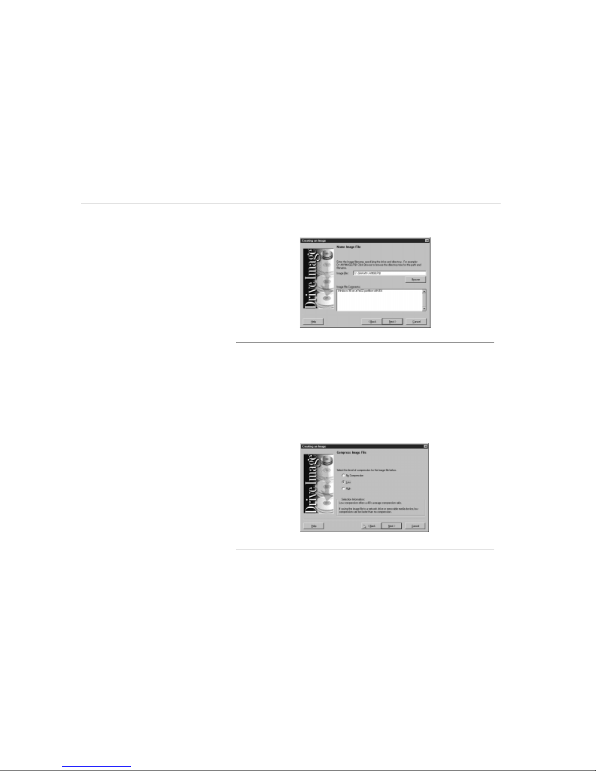
Drive Image 3.0
Chapter Seven - Software Utilities
86
hard drives, network drives, and removable media storage devices such as
Jaz, Zip, MO, and SyQuest drives. Network drives must be visible as a drive
letter.
Figure 39. Drive Image Name Image File Screen
10.(Optional) Type brief comments in the
Image File Comments
field. Click
Next.
Select the desired compression level.
• No
Compression
is usually the fastest method for creating an image file
and is useful if storage space is not an issue. However, if you are saving
your image file to a busy network drive or to a relatively slow removable
media device, high compression may be faster than no compression since
there is less data to write to the file.
•
Low
compression offers a 40% average compression ratio.
•
High
compression offers a 50% average compression ratio.
Figure 40. Drive Image Compress Image File Screen
Page 87
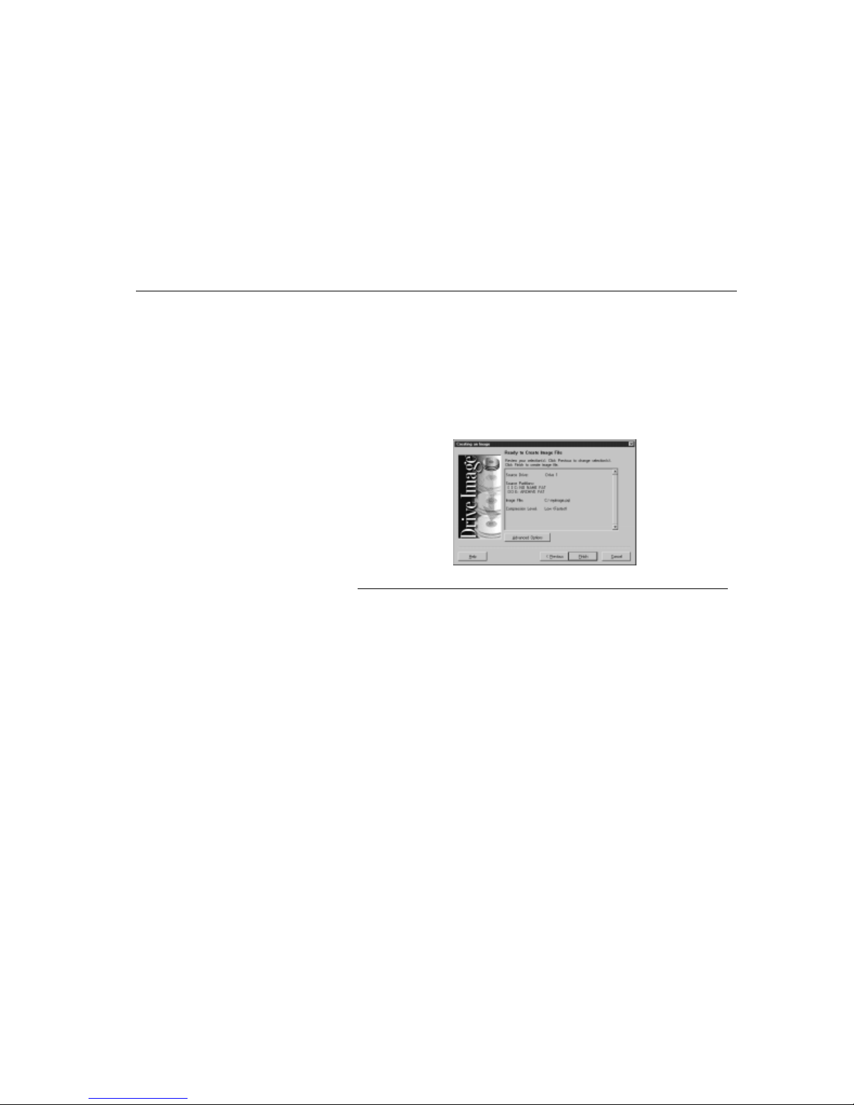
Drive Image 3.0
Chapter Seven - Software Utilities
87
In general, compressed image files created with new versions of Drive Image are
not compatible with earlier versions.
11.Click Next. Drive Image displays all the information you have entered to this
point:
• Source Drive
• Source Partitions (partitions to be included in the image file are marked
with an “X”)
• Image Filename
• Compression Level
Figure 41. Drive Image Ready To Create Image File Screen
To modify any settings, click Previous.
12.Click Advanced Options to set such options as disabling file system errorchecking or pass word-protecting your image file.
13.Click Finish to begin creating the image file.If you entered a name of a current
file, Drive Image displays a message that <
path and filename
> already exists.
You can replace the existing file or choose a new filename. If Drive Image
detects that you are saving your image file to removable media, it enables a
media-spanning feature that spreads the image file over a series of disks. You
must have at least 100K of available space on each disk in the series.
Page 88
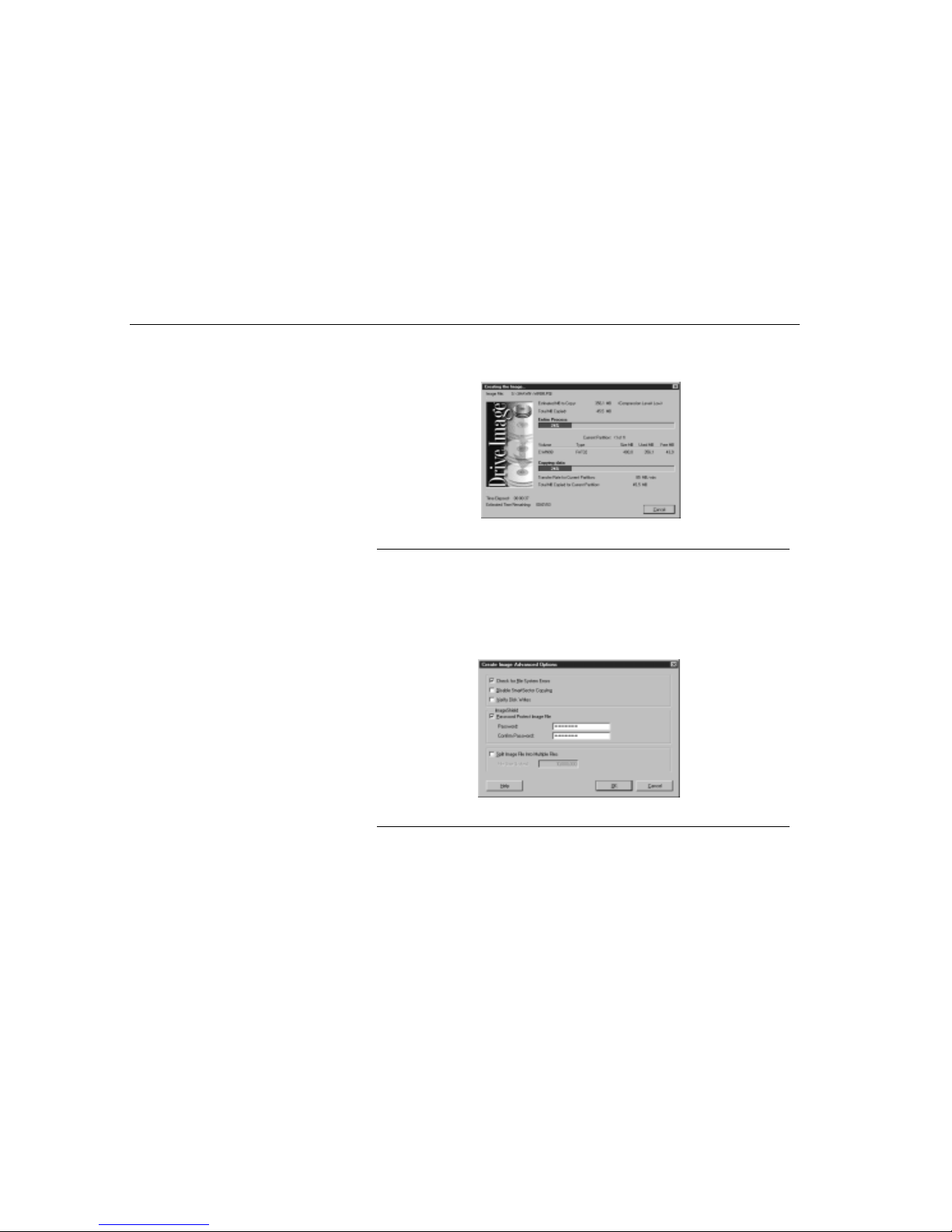
Drive Image 3.0
Chapter Seven - Software Utilities
88
If you use the media-spanning feature, be sure to number the media in order,
since you must insert them in sequence when restoring the image file. The
Creating the Image dialog appears.
Figure 42. Drive Image Creating The Image Screen...
Upon completion, the following message appears: “Image was copied
successfully to file: <
image filename
>.“
14.Click OK to return to the Drive Image main screen.
Advanced Options
The Create Image Advanced Options dialog box appears when you click
Advanced Options at the Ready To Create Image File screen.
Figure 43. Drive Image Create Image Advanced Options
Clear the Check for File System Errors check box if you want to disable file
system error checking.
Page 89

Drive Image 3.0
Chapter Seven - Software Utilities
89
If you have already used a disk utility program such as ScanDisk to check your
hard drive for errors, it is not necessary to have Drive Image check for file system
errors. Clearing Check for File System Errors saves time in creating the image
file. If you did not run a disk check utility program before loading Drive Image,
leave the Check for File System Errors check box selected.
Disable SmartSector Copying
Drive Image’s SmartSector technology speeds up the imaging process by only
copying clusters and sectors which contain data. However, in some cases, such
as high-security environments, it may be desirable to copy all clusters and sectors
in their original layout, whether or not they contain data.
To copy both used and unused clusters and sectors, click Disable SmartSector
Copying. Disabling SmartSector copying increases processing time and the size
of the generated.PQI file.
Verify Disk Wri tes
Click Verify Disk Writes if you want to enable DOS disk write verification.
Disk write verification is not critical to safely create image files. Enabling disk write
verification can slow the image file creation by as much as seven times.
ImageShield
To password-protect your image file, click Password Protect Image File and
type a password in the Password field.
N
OTE
:
Note image file passwords and store them in a safe place. If you forget an image
file’s password, you cannot restore the file.
Split Image File Into Multiple Files
Sometimes it is useful to force Drive Image to split a large image file into smaller
files. To do so, click Split Image File Into Multiple Files and enter the maximum
byte size for each file in the File Size (bytes) field. If you wish to save the files to
CDs, specify a file size of 650,000,000 bytes (650 MB) or less.
Restoring Image Files
• If you are restoring an image file to set up a new hard drive on a machine
with a BIOS older than 1994, see “Using Drive Image with Drive Overlay
Software” in the Drive Image manual on the MRestore CD, located at
PQtools\userinfo.
• To restore selected files from a compressed or spanned image file, see
“Restoring Files from Spanned or Compressed Images” in Drive Image
manual included on the MRestore CD.
Page 90
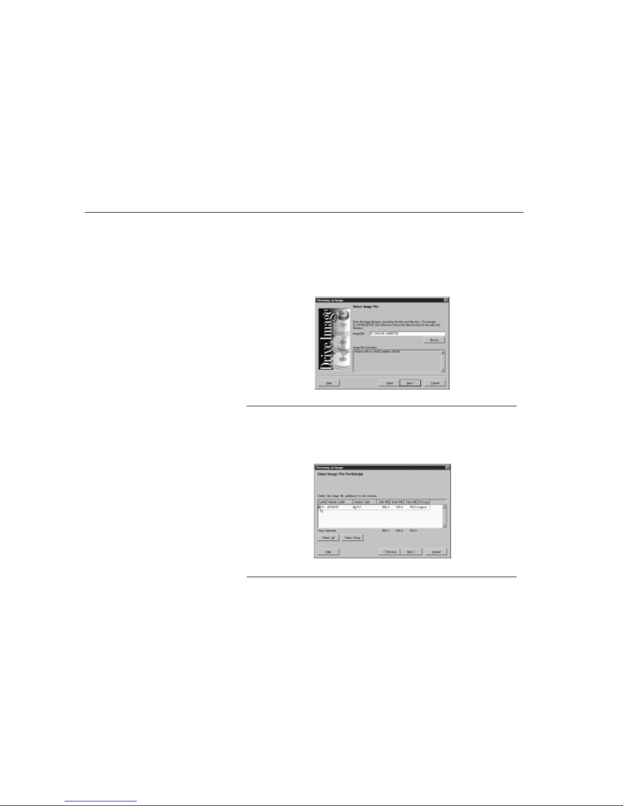
Drive Image 3.0
Chapter Seven - Software Utilities
90
To restore an image file to a different drive or partition:
1. Ensure that virus protection is disabled in the BIOS. If virus protection is
enabled, Drive Image will hang when you click Finish at this end of this
procedure.
2. Start Drive Image, then click Restore Image.
3. In the Image File field, enter the path and filename of the image file you want
to restore, or click Browse to select the path and image file.
Figure 44. Drive Image Restoring An Image Screen
4. Click Next. At any point prior to actual image file restore, you can click Back to
return to the previous step and change your settings.
5. If you have more than one partition, you can select the partitions you want to
restore. Select the image file partitions, or click Select All. A check appears to
the left of the selected partitions.
Figure 45. Drive Image Resize Partitions Screen
Page 91
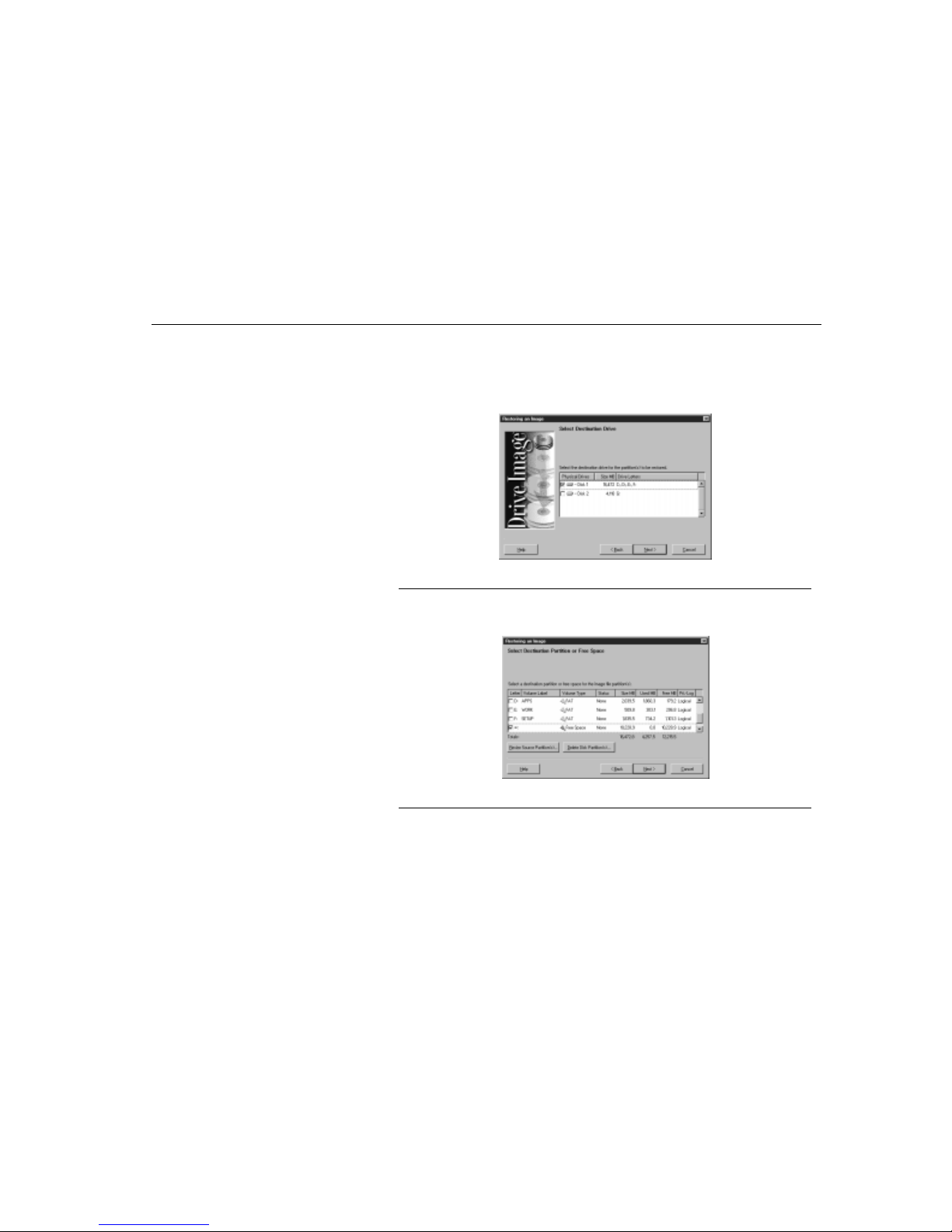
Drive Image 3.0
Chapter Seven - Software Utilities
91
6. To deselect partitions, click again on a partition or click Select None.The Total
Selected field keeps a running total of the disk space for all selected partitions,
including total used and free space.
7. Click Next. If you have more than one hard drive, select the drive where you
want to restore the image file.
Figure 46. Drive Image Restoring An Image File Screen
8. Click Next.
9. Select an existing partition or free space (non-partitioned disk space).
Figure 47. Drive Image Restoring An Image File (Select Destination) Screen
10.If the destination partition or free space is not large enough to accommodate
the partitions you wish to restore, or if you are restoring the image file to a
larger drive and want to set a specific size for partitions rather than use the
proportional resize option, you may want to resize the partitions. If this does
not apply to you, go to Step 17 on page 94.
Page 92
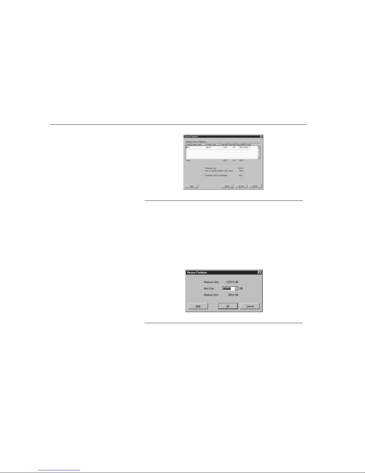
Drive Image 3.0
Chapter Seven - Software Utilities
92
11.Click Resize Source Partitions. The Resize Partitions window displays.
Figure 48. Drive Image Resize Partitions Screen
The Selected Source Partitions group box displays the partitions you selected to
restore. The Totals field displays the disk space for the source partitions. A
formula box below the Totals field displays:
• Destination Size
• Current Size of Selected Partition
• Remaining Space in Destination
12.Click Resize. The Resize Partition window appears. The Maximum Size field
displays the largest possible size the source partitions can have and still fit in
the destination space. The Minimum Size field shows the smallest possible
size the source partitions can occupy.
Figure 49. Drive Image Resize Partition (New Size) Screen
13.In the New Size field, enter a number that is less than the Maximum Size and
greater than or equal to the Minimum Size.
Page 93
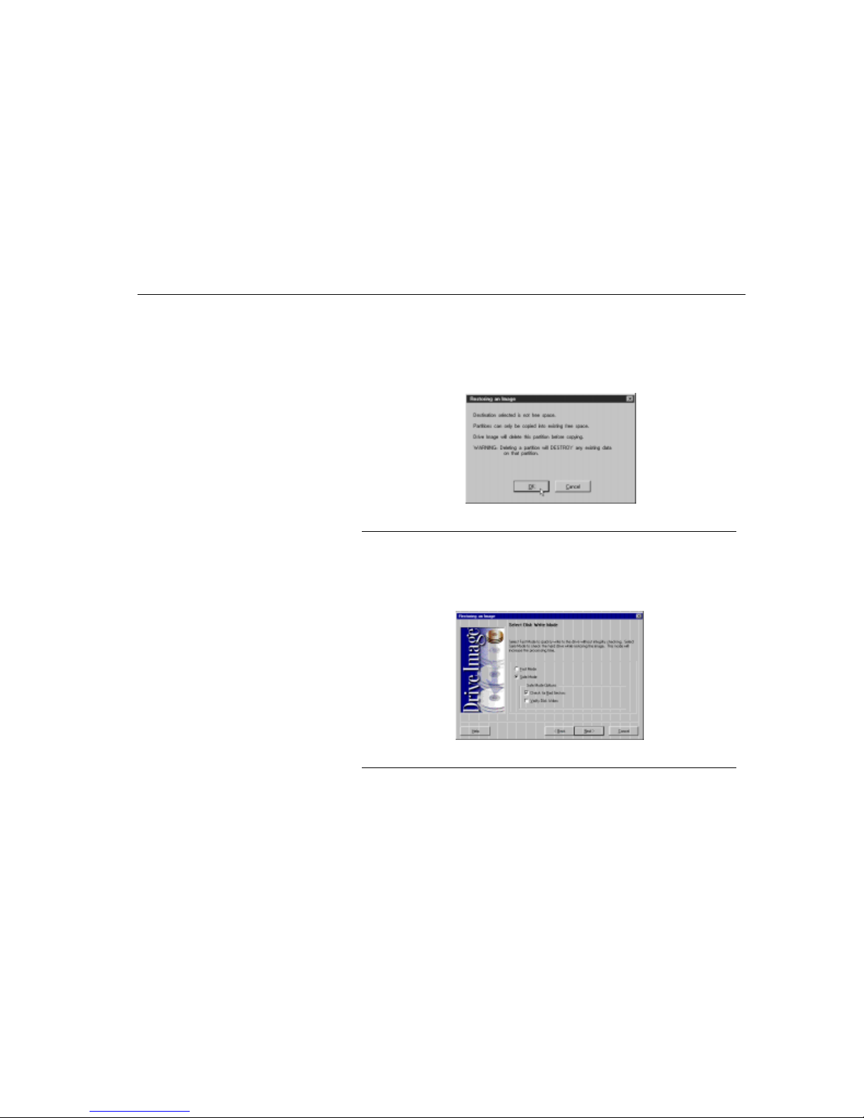
Drive Image 3.0
Chapter Seven - Software Utilities
93
14.Click OK. Since partitions must end on a cylinder boundary, Drive Image
rounds the New Size up to the next cylinder boundary.
15.Click Accept. Later, when you restore the image file, Drive Image resizes the
partition.
16.Click Next. If you selected an existing partition as the destination, the following
message appears.
Figure 50. Drive Image Restoring An Image (Warning) Screen
Drive Image does not delete the partition until you click Finish on the Ready to
Restore Image File screen. If the free space on the destination drive is greater
than the space required to restore the selected partitions, the Resize Options
dialog appears. For more information, refer to the Drive Image manual, available
on the MRestore CD. The Select Disk Write Mode dialog box appears.
Figure 51. Drive Image Restoring An Image (Select Disk Write Mode) Screen
Page 94
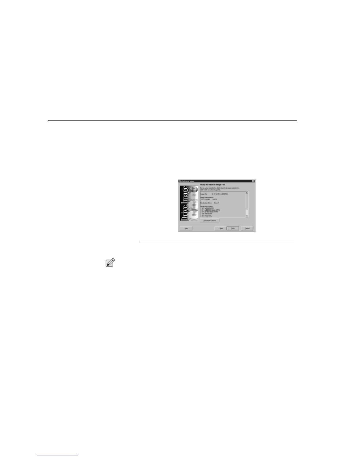
Drive Image 3.0
Chapter Seven - Software Utilities
94
17.Click the disk write mode you want.
• Fast is the quickest way to restore an image.
• Safe checks for bad sectors and enables DOS disk write verification. You
can also enable the safe options independently using the Advanced
Options button in Step 19. For example, if you want to enable DOS disk
write verification but not check for bad sectors, you can use Advanced
Options instead of clicking Safe mode in this dialog box.
18.Drive Image displays all the information you have entered to this point. To
modify any settings, click Back.
Figure 52. Drive Image Restoring An Image (Ready to Restore Image) Screen
19.If you wish to enable bad-sector checking or turn on DOS disk write
verification, click Advanced Options.
N
OTE
:
Restoring multiple logical partitions can cause the drive letters of subsequent
partitions to change. This may make the computer unbootable or cause
applications to fail.
20.Click Finish to begin restoring the image file.
21.If you assigned a password to the image file when you created it, the Get
Image File Password dialog appears. You must enter the correct password in
order to restore the image file.
Page 95

Drive Image 3.0
Chapter Seven - Software Utilities
95
The Restoring the Image dialog appears, tracking the following items:
• Image filename
• Estimated megabytes to restore
• Total megabytes copied
• Entire process progress bar
• Information about current partition (volume, type, size MB, used MB, free
MB)
• Sub-process progress bar
• Transfer rate for current partition
• Total megabytes copied for current partition
• Time elapsed
• Estimated time remaining
Upon completion, the message “Image was restored successfully” appears.
22.Click OK to return to the Drive Image main screen.
Resize Options
The following options are available when restoring partitions if the free space on
the destination drive is greater than the space required by the partitions.
• Automatically resize partitions proportionally to fit. Click this option to
allow Drive Image to automatically expand the partitions in equal
proportions to occupy the destination drive’s remaining free space.
• Leave remaining free space. Click this option if you want to leave any
remaining free space unused on the destination drive after the partitions
are restored.
• Resize partitions manually to fit. Click this option to display the Resi ze
Partition window where you can manually set the size of the partitions to fit
in the destination drive’s remaining free space.
Page 96
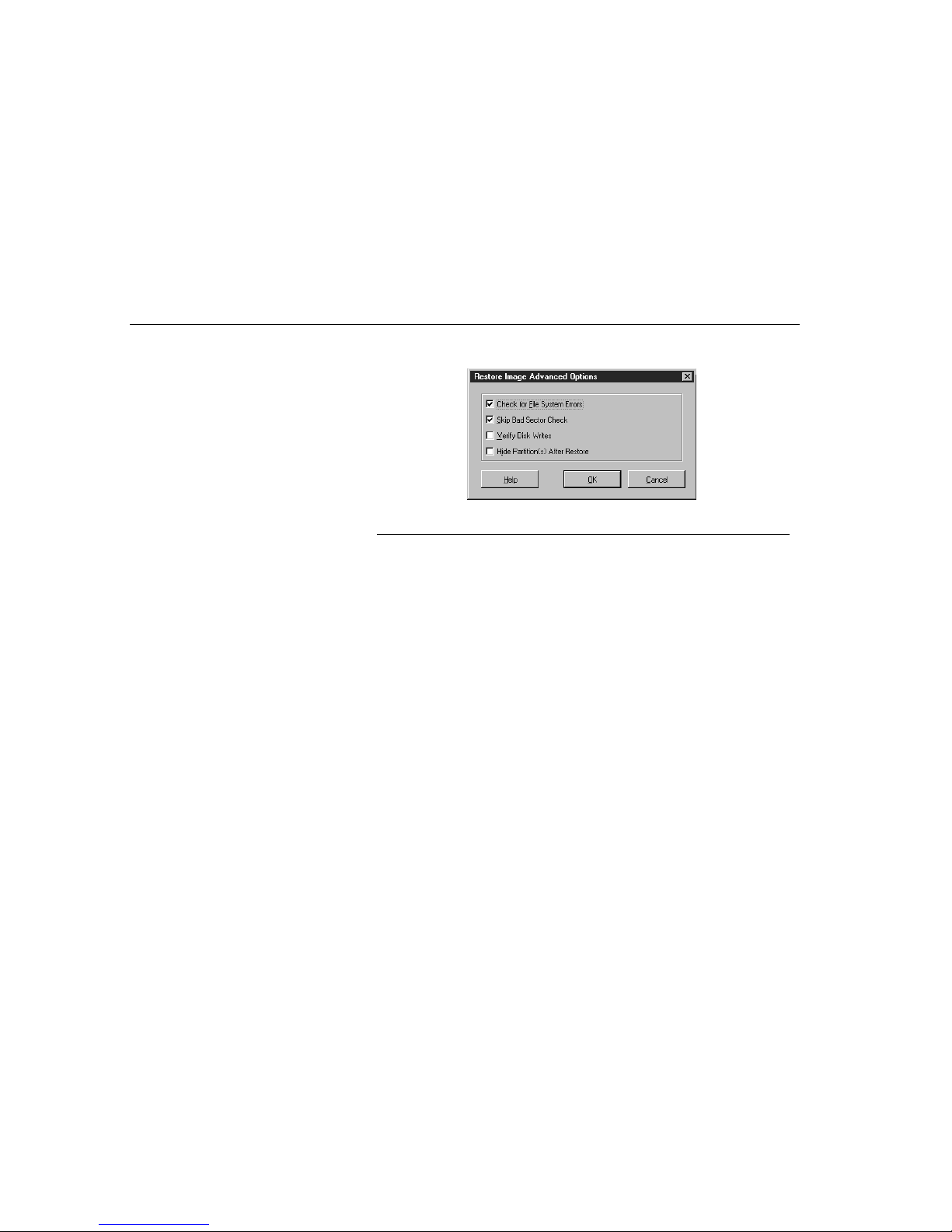
PartitionMagic
Chapter Seven - Software Utilities
96
Advanced Options
At the
Ready To Restore Image File
screen, click
Advanced Options
to access
the following.
Figure 53. Drive Image Restore Image Advanced Options Screen
Check for File System Errors
Clear the
Check for File System Errors
check box to disable file system error
checking. If you have already used a disk utility program such as ScanDisk to
check your hard drive for errors, it is not necessary to have Drive Image check for
file system errors. Clearing this option saves time in restoring images. Note that
Drive Image cannot restore partitions with file system errors.
Skip Bad Sector Check
To save time in restoring the image file, set this option. Although most drives do
not have bad sectors, the potential for problems increases during the lifetime of
the hard drive. If you have an older hard drive, it is wise to enable bad-sector
checking.
Verify Check Writes
Click
Verify Disk Writes
if you want to enable DOS disk write verification. Disk
write verification is not critical to safely restore image files. Enabling disk write
verification can slow the image restore process by as much as seven times.
PartitionMagic
Imagine how disorganized your office would be if you kept all your files in one
drawer. Surprisingly, this is similar to the way many people organize the space on
their hard disks. With PartitionMagic, you can quickly and easily create separate
“file drawers,” or partitions, on your hard disks for storing valuable information
such as data files, applications, and operating systems. Storing information in
separate partitions helps you organize and protect your data, safely run multiple
operating systems, and reclaim wasted disk space.
Page 97
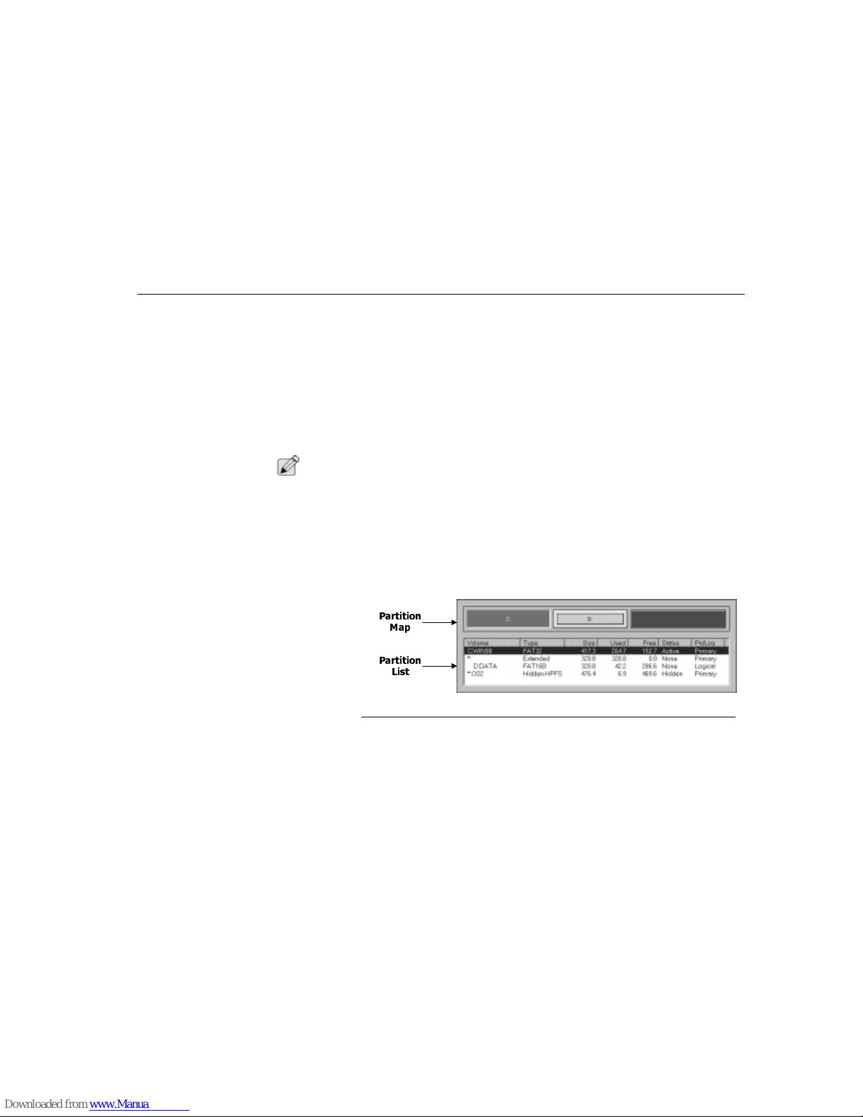
PartitionMagic
Chapter Seven - Software Utilities
97
PartitionMagic enables you to secure your data by physically separating it from
other files. Separate partitions also make backups to networks and removable
drives easy.
Because of limitations with the FAT file system which is used by many popular
operating systems such as DOS and Windows 95, as much as 40 percent of your
hard-disk space can be wasted. PartitionMagic reclaims wasted space quickly
and safely by using more efficient partition sizes. It can also convert FAT
partitions to FAT32 and vice versa. With Windows NT you are required to use the
convert program provided by the operation system.
With PartitionMagic, partitioning your hard disk has never been easier.
N
OTE
:
We recommend creating an image file before installing or changing anything on
your system.
In the
PartitionMagic
main window, the menu bar and a toolbar appear at the top
of the window. The menu bar gives you access to all of PartitionMagic’s features,
while the toolbar gives you quick access to commonly-used options.
Partition Informa t io n
The partition area displays information about the selected hard disk’s partitions. It
consists of two areas: the partition map, which displays information graphically;
and the partition list, which displays partition information in text form.
Figure 54. Drive Image Partition Information
Partition Map
The partition map shows the partitions approximately to scale. Each partition is
represented by a different color according to the file system it uses. If the selected
hard disk contains logical partitions, the logical partitions are shown within an
extended partition.
3DUWLWLRQ
0DS
3DUWLWLRQ
/LVW
Page 98

PartitionMagic
Chapter Seven - Software Utilities
98
Partition List
The partition list displays the following information about each partition: drive
letter, volume label, file system type, size, amount of used and free space, status,
and whether t he partition is a primary or logi cal partition.
Primary partition drive letters are flush left, followed by a colon and the volume
name. Logical partition drive letters and volume labels are indented. An asterisk
(*) appears in place of a drive letter for:
• Hidden partitions
• Extended partitions
• Partitions with file systems not supported by the active operating system
• Free space
The partition size, used space, and free space values are displayed in megabytes.
A partition’s status can be:
• Active: The partition the computer boots from.
• None: Partitions that are not active or hidden.
You can navigate PartitionMagic using the mouse or the keyboard.
The partition size, used space, and free space values are displayed in megabytes.
To navigate using a mouse, position the mouse pointer on the item you want to
select and click the primary (usually the left) mouse button. This action is simply
referred to as “clicking” or “click.” While you can make most of your selections
using the mouse, a few options require you to type information.
By positioning the pointer on a partition in the partition map or on the partition list
and clicking the secondary (usually the right) mouse button, you can display a
context menu containing the Operations menu options. This action is simply
referred to as “right-clicking” or “right-click.” To select an option on the context
menu, click the option.
PartitionMagic Help
While using PartitionMagic, you can quickly get both comprehensive and contextsensitive help when you need it. PartitionMagic’s comprehensive online Help
system provides in-depth information on PartitionMagic’s features as well as
step-by-step instructions on performing specific tasks.
To access Help, click
Help
>
Contents
on the menu bar in the
PartitionMagic
main window. The
Help Contents
page organizes the Help system into books
and pages.
Page 99

PartitionMagic
Chapter Seven - Software Utilities
99
N
OTE
:
Some help topic reference applications are not available with MRestore CD.
ReadMe File
README.TXT is an invaluable resource for the most current information at the
time the product shipped. It includes information that may have changed since this
guide was printed, corrections to the manual or help system, and information
specific to installation or configuration issues.
Completing Tasks Manually
To manually complete a task, follow this general four-step process:
1. Select a hard disk.
2. Select a partition.
3. Select an operation.
4. Apply changes to your system.
Selecting a Hard Disk
The
Disk
option on the toolbar displays the currently selected disk and its size in
megabytes (MB).
To select a disk:
On the toolbar, click the arrow button to the right of the currently selected disk to
open a drop-down list of all the disks on your system, and then click the disk you
want to select.
OR
On the menu bar, click
Drives
and then select a disk.
N
OTE
:
Drives does not appear on the menu bar unless you have multiple hard disks.
Selecting a Partition
The selected partition is highlighted in the partition list.
To select a partition:
Click the partition in the partition list or on the partition map.
When you manually complete a task, you most often use the Operations menu.
After you have selected a disk and a partition, you can select an operation using
the toolbar, the context menu, the menu bar, or the keyboard.
Page 100

PartitionMagic
Chapter Seven - Software Utilities
100
N
OTE
:
If an operation cannot be performed on the selected partition, the operation is
unavailable.
To select an operation,
On the toolbar, click the
Operations
button.
When you place the pointer on a toolbar button, a pop-up window appears
describing the button’s function.
OR
In the partition map or partition list, right-click the partition you want to change,
and then click the desired operation from the context menu.
OR
On the menu bar, click
Operations
then choose the desired operation.
Applying Changes to Your System
As you complete tasks using the Operations menu, the partition map and partition
list reflect the changes you have made. However, no changes physically take
place on your system until you apply them.
You can tell when changes have been made but not yet applied to your system
when: (1) the Apply option appears in the main window, and (2) the status box in
the lower right corner of the main window indicates that operations are pending.œ
To apply changes to your system, click
Apply
or click on the toolbar. If you wish to
discard the changes and start over, click on the toolbar.
You can also apply and discard changes using the
General
menu.
Changing PartitionMagic
Preferences
From the General menu, you can change various program preferences. Each
preference is a toggle and, like a light switch, is either on (enabled) or off
(disabled). A check mark next to a preference indicates it is enabled.
System supports FAT32 indicates whether the current operating system supports
FAT32 partitions. Windows 95 OEM Service Release 2, Windows 98, and
Windows NT 2000 support FAT32 partitions; other operating systems do not.
 Loading...