

Micronas Intermetall MSP4428G, MSP4448G, MSP4408G, MSP4418G Datasheet
PRELIMINARY DATA SHEET
MICRONAS
MSP 44x8G
Multistandard
Sound Processor
Edition Feb. 25, 2000
6251-516-1PD
MICRONAS

MSP 44x8G PRELIMINARY DATA SHEET
Contents
Page Section Title
5 1. Introduction
6 1.1. Features of the MSP 44x8G Family
6 1.2. MSP 44x8G Version List
7 1.3. MSP 44x8G Versions and their Application Fields
8 2. Functional Description
8 2.1. Architecture of the MSP 44x8G Family
9 2.2. MSP 44x8G Sound IF Processing
9 2.2.1. Analog Sound IF Input
9 2.2.2. Demodulator: Standards and Features
9 2.2.3. Preprocessing of Demodulator Signals
10 2.2.4. Automatic Sound Select
10 2.2.5. Manual Mode
2
12 2.3. Preprocessing for SCART and I
12 2.4. Source Selection and Output Channel Matrix
12 2.4.1. Mixing Unit
12 2.5. Audio Baseband Processing
12 2.5.1. Automatic Volume Correction (AVC)
13 2.5.2. Main and Aux Outputs
13 2.5.3. Quasi-Peak Detector
13 2.6. SCART Signal Routing
13 2.6.1. SCART DSP In and SCART Out Select
13 2.6.2. Stand-by Mode
2
13 2.7. I
13 2.7.1. Synchronous I
13 2.7.2. Asynchronous I
S Bus Interfaces
2
S-Interface(s)
2
S-Interface
14 2.8. ADR Bus Interface
14 2.9. Digital Control I/O Pins and Status Change Indication
14 2.10. Preemphasis
14 2.11. Clock PLL Oscillator and Crystal Specifications
S Input Signals
15 3. Control Interface
2
15 3.1. I
C Bus Interface
15 3.1.1. Device and Subaddresses
16 3.1.2. Description of CONTROL Register
16 3.1.3. Protocol Description
2
17 3.1.4. Proposals for General MSP 44x8G I
C Telegrams
17 3.1.4.1. Symbols
17 3.1.4.2. Write Telegrams
17 3.1.4.3. Read Telegrams
17 3.1.4.4. Examples
2
17 3.2. Start-Up Sequence: Power-Up and I
C Controlling
17 3.3. MSP 44x8G Programming Interface
17 3.3.1. User Regi sters Overview
20 3.3.2. Description of User Registers
21 3.3.2.1. STANDARD SELECT Register
21 3.3.2.2. STANDARD RESULT Register
2 Micronas

PRELIMINARY DATA SHEET
Contents, continued
Page Section Title
MSP 44x8G
22 3.3.2.3. Write Registers on I2C Subaddress 10
25 3.3.2.4. Read Registers on I2C Subaddress 11
26 3.3.2.5. Write Registers on I2C Subaddress 12
33 3.3.2.6. Read Registers on I2C Subaddress 13
hex
hex
hex
hex
34 3.4. Programming Tips
34 3.5. Examples of Minimum Initialization Codes
34 3.5.1. B/G-FM (A2 or NICAM)
34 3.5.2. BTSC-Stereo
34 3.5.3. BTSC-SAP with SAP at Main Channel
35 3.5.4. FM-Stereo Radio
35 3.5.5. Automatic Standard Detection
35 3.5.6. Software Flow for Interrupt driven STATUS Check
37 4. Specifications
37 4.1. Outline Dimensions
39 4.2. Pin Connections and Short Descriptions
42 4.3. Pin Descriptions
45 4.4. Pin Configurations
48 4.5. Pin Circuits
50 4.6. Electrical Characteristics
50 4.6.1. Absolute Maximum Ratings
51 4.6.2. Recommended Operating Conditions (T
= 0 to 70 °C)
A
51 4.6.2.1. General Recommended Operating Conditions
51 4.6.2.2. Analog Input and Output Recommendations
52 4.6.2.3. Recommendations for Analog Sound IF Input Signal
53 4.6.2.4. Crystal Recommendations
54 4.6.3. Characteristics
54 4.6.3.1. General Characteristic s
55 4.6.3.2. Digital Inputs, Digital Outputs
56 4.6.3.3. Reset Input and Power-Up
2
57 4.6.3.4. I
58 4.6.3.5. I
C-Bus Characteristics
2
S-Bus Characteristics
60 4.6.3.6. Analog Baseband Inputs and Outputs, AGNDC
62 4.6.3.7. Sound IF Inputs
62 4.6.3.8. Power Supply Rejection
63 4.6.3.9. Analog Performance
66 4.6.3.10. Sound Standard Dependent Characteristics
69 5. Appendix A: Overview of TV-Sound Standards
69 5.1. NICAM 728
70 5.2. A2-Systems
71 5.3. BTSC-Sound System
71 5.4. Japanese FM Stereo System (EIA-J)
72 5.5. FM Satellite Sound
72 5.6. FM-Stereo Radio
Micronas 3

MSP 44x8G PRELIMINARY DATA SHEET
Contents, continued
Page Section Title
73 6. Appendix B: Manual Mode
73 6.1. Demodulator Write and Read Registers for Manual Mode
74 6.2. DSP Write and Read Registers for Manual Mode
74 6.3. Manual Mode: Description of Demodulator Write Registers
74 6.3.1. Automatic Switching between NICAM and Analog Sound
74 6.3.1.1. Function in Automatic Sound Select Mode
75 6.3.1.2. Function in Manual Mode
76 6.3.2. A2 Threshold
76 6.3.3. Carrier-Mute Threshold
77 6.3.4. DCO-Registers
77 6.4. Manual Mode: Description of Demodulator Read Registers
78 6.4.1. NICAM Mode Control/Additional Data Bits Register
78 6.4.2. Additional Data Bits Register
78 6.4.3. CIB Bits Register
78 6.4.4. NICAM Error Rate Register
79 6.5. Manual Mode: Description of DSP Write Registers
79 6.5.1. Additional Channel Matrix Modes
79 6.5.2. FM Fixed Deemphasis
79 6.5.3. FM Adaptive Deemphasis
79 6.5.4. NICAM Deemphasis
79 6.5.5. Identification Mode for A2 Stereo Systems
80 6.6. Manual Mode: Description of DSP Read Registers
80 6.6.1. Stereo Detection Register for A2 Stereo Systems
80 6.6.2. DC Level Register
80 6.7. Demodulator Source Channels in Manual Mode
80 6.7.1. Terrestrial Sound Standards
80 6.7.2. SAT Sound Standards
82 7. Appendix C: Application Information
82 7.1. Exclusions of Audio Baseband Features
82 7.2. Phase Relationship of Analog Outputs
83 7.3. Application Circuit
84 8. Data Sheet History
4 Micronas
PRELIMINARY DATA SHEET MSP 44x8G
Multistandard Sound Processor Family
1. Introduction
The MSP 44x8G family of Multistandard Sound Processors covers the soun d proce ssi ng of a ll anal og T VStandards worldwide, as well as the NICAM digital
sound standards. The fu ll TV so und processing , star ting with analog sound IF signa l-in, down to process ed
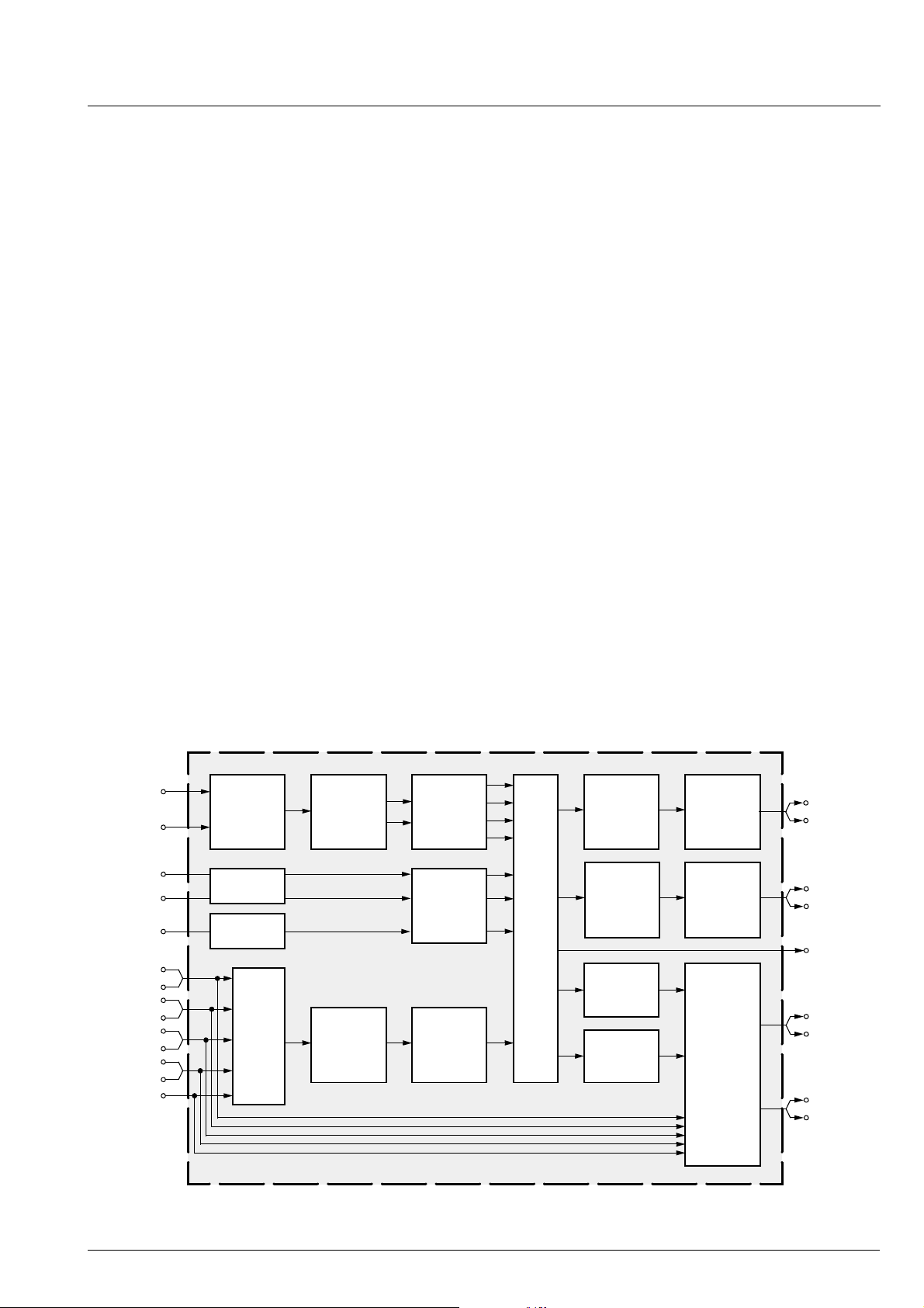
analog AF-out, is perform ed on a single chi p. Fig. 1–1
shows a simplified functional block diagram of the
MSP 44x8G.
The high-quality A /D and D/A converters offer the full
audio bandwidth of 20 kHz and the backend DSP processing is performed at a 48 kHz sample rate.
The MSP 44x 8G has been designed for the usage in
hybrid set-top boxes and multimedia applications. Its
asynchronous I
2
S slave interface allows the recepti on
of digital stereo signals with arbitrary sample rates
ranging from 5 to 50 kHz. Synchronization is performed by means of an adaptive sample rate converter.
This generation of TV soun d processing ICs includes
versions for processing the multichannel television
sound (MTS) signal conforming to the standard recommended by the Broadcast Television Systems Committee (BTSC). The DBX noise red uction, or alter nati vely,
Micronas Noise Reductio n (MNR) is performed alignment free.
Other processed s tandards are the Japanese FM-FM
multiplex standard (EIA-J) and the FM Stereo Radio
standard.
The MSP 44x 8G versions are pin and software compatible to other MSP families. Standard selection
requires only a single I
2
C transmission.
The MSP 44x8G has built-in automatic functions: The
IC is able to detect the actual sound standard automatically (Automatic Standard Detection). Furthermore,
pilot levels and identification sign als can be evaluated
internally with subsequent switching between mono/
stereo/bilingual; no I
2
C interaction is ne cessar y (Auto-
matic Sound Selection).
The ICs are produced in submicron CMOS technology
and are available in the following packages: PQFP 80,
PLQFP64, and PSDIP64.
Sound IF1
Sound IF2
I2S1
I2S2
I2S3
SCART1
SCART2
SCART3
SCART4
MONO
ADC
synchron.
2
I
S
asychron.
2
S
I
SCART
DSP
Input
Select
De-
modulator
ADC
Pre-
processing
Prescale
Prescale
Fig. 1–1: Simplified functional block diagram of the MSP 44x8G
Main
Sound
Processing
Aux
Sound
Processing
Source Select
DAC
DAC
DAC
DAC
DAC
SCART
Output
Select
Main
Channel
Aux
Channel
I2S
SCART1
SCART2
Micronas 5
MSP 44x8G PRELIMINARY DATA SHEET
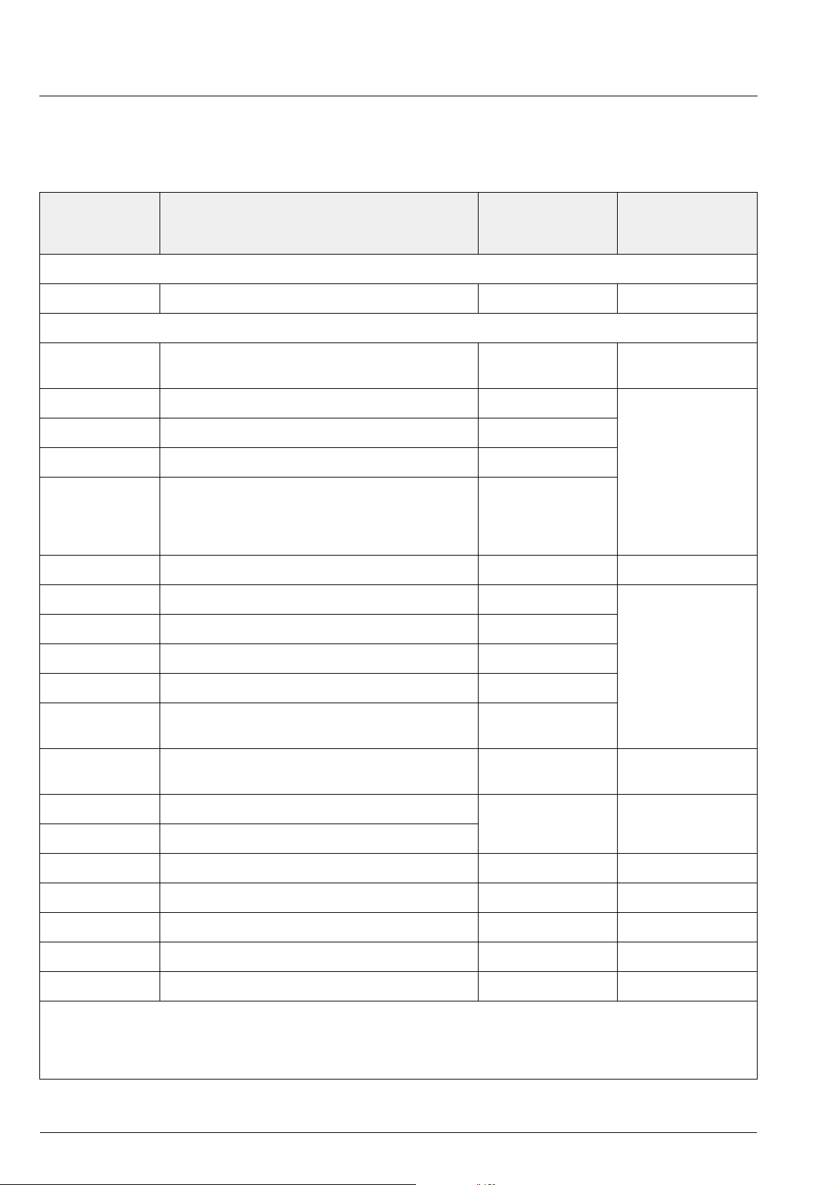
1.1. Features of the MSP 44x8G Family
Feature 4408 4418 4428 4448 4458
2
Standard Selection with single I
Automatic Standard Detection of terrestrial TV standards X X X X X
Automatic Sound Selection (mono/stereo/bilingual), new registers MODUS, STATUS X X X X X
Two selectable sound IF (SIF) inputs X X X X X
Automatic Carrier Mute function X X X X X
Interrupt output programmable (indicating status change) X X X X X
Main/Aux channel with volume, balance, bass, treble, loudness X X X X X
AVC: Automatic Volume Correction X X X X X
Two channel mixer XXXXX
Selectable preemphasis for Aux channel X X X X X
Four Stereo SCART (line) inputs, one Mono input; two Stereo SCART outputs X X X X X
Complete SCART in/out switching matrix X X X X X
2
Two 48kHz I
S inputs; one ansynchronous 5..50 kHz I2S input, one 48 kHz I2S output X X X X X
C transmission X X X X X
All analog FM-Stereo A2 and satellite standards; AM-SECAM L standard X X X
Simultaneous demodulation of (very) high-deviation FM-Mono and NICAM X X
Adaptive deemphasis for satellite (Wegener-Panda, acc. to ASTRA specification) X X X
ASTRA Digital Radio (ADR) together with DRP 3510A X X X
All NICAM standards XX
Demodulation of the BTSC multiplex signal and the SAP channel X X X
Alignment free digital DBX noise reduction for BTSC Stereo and SAP X X
Alignment free digital Micronas Noise Reduction (MNR) for BTSC Stereo and SAP X
BTSC stereo and EIA-J separation significantly better than spec. X X X
SAP and stereo detection for BTSC system XXX
Korean FM-Stereo A2 standard X X X X X
Alignment-free Japanese standard EIA-J XXX
Demodulation of the FM-Radio multiplex signal X X X
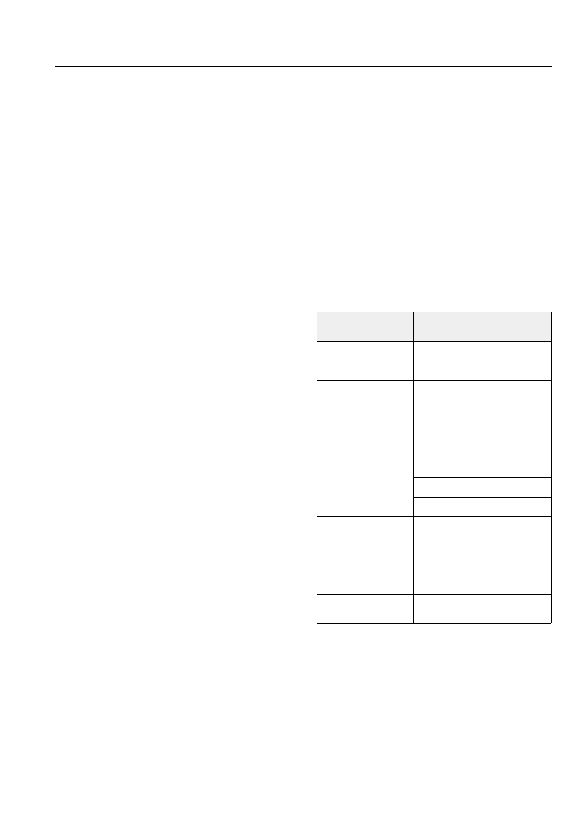
1.2. MSP 44x8G Version List
Version Status Description
MSP 4408G planned FM Stereo (A2) Version
MSP 4418G planned NICAM and FM Stereo (A2) Version
MSP 4428G planned NTSC Version (A2 Korea, BTSC with Micronas Noise Reduction (MNR), and Japanese EIA-J system)
MSP 4448G planned NTSC Version (A2 Korea, BTSC with DBX noise reduction, and Japanese EIA-J system)
MSP 4458G available Global Version (all sound standards)
6 Micronas
PRELIMINARY DATA SHEET MSP 44x8G
1.3. MSP 44x8G Versions and their Application Fields
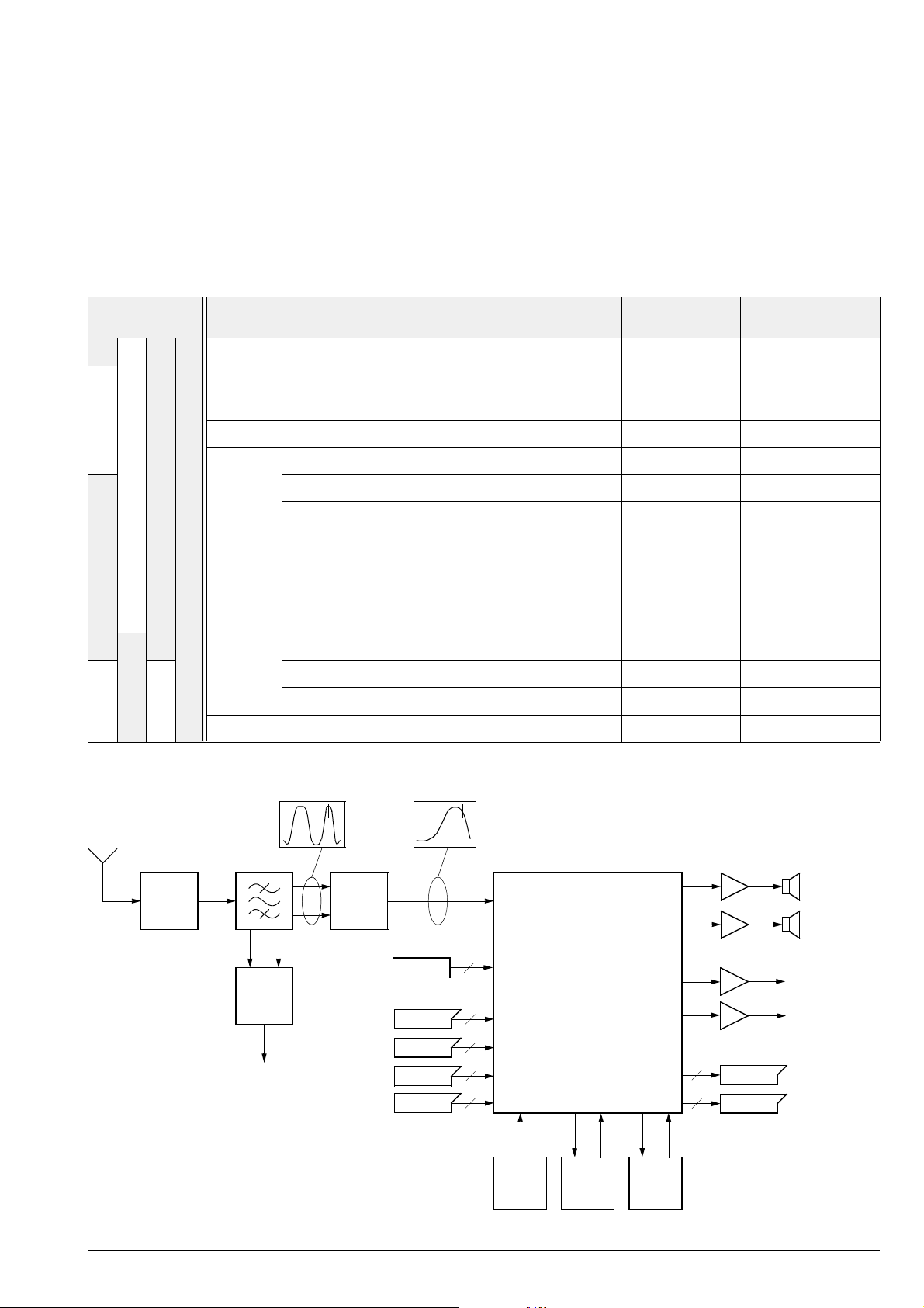
Table 1–1 provides an overview of TV sound standards
that can be processed by the MSP 44x8G family. In
addition, the MSP 44x8G is able to handle the terrestrial FM-Radio stand ard. W ith the MSP 44x8G, a com-
plete multimedia r eceiver covering all TV sound standards together with terrestrial and satellite radio sound
can be built; even ASTRA Digital Radio can be processed (with a DRP 3510A coprocessor).
Table 1–1: TV Stereo Sound Standards covered by the MSP 44x8G Family (details see Appendix A)
MSP Version System Position of Sound
4408
4418
4408
B/G
L 6.5/5.85 AM-Mono/NICAM SECAM-L France
I 6.0/6.552 FM-Mono/NICAM PAL UK, Hong Kong
D/K
4458
Satellite
Carrier / MHz
5.5/5.7421875 FM-Stereo (A2) PAL Germany
5.5/5.85 FM-Mono/NICAM PAL Scandinavia, Spain
6.5/5.85 FM-Mono/NICAM PAL China, Hungary
6.5/6.2578125 FM-Stereo (A2, D/K1) SECAM-East Slovak. Rep.
6.5/6.7421875 FM-Stereo (A2, D/K2) PAL currently no broadcast
6.5/5.7421875 FM-Stereo (A2, D/K3) SECAM-East Poland
6.5
7.02/7.2
7.38/7.56
etc.
Sound
Modulation
FM-Mono
FM-Stereo
ASTRA Digital Radio (ADR)
with DRP 3510A
Color
System
PAL
Broadcast e.g. in:
Europe Sat.
ASTRA
4428/48
Tuner
4.5/4.724212 FM-Stereo (A2) NTSC Korea
M
FM-Radio 10.7 FM-Stereo Radio USA, Europe
SAW Filter
Vision
Demodulator
COMPOSITE
Video
4.5 FM-FM (EIA-J) NTSC Japan
4.5 BTSC-Stereo + SAP NTSC USA
33 34 39MHz 4.5 9MHz
Sound
IF
Mixer
1
2
2
2
2
MSP 44x8G
2
2
SCART1
SCART2
SCART
Inputs
Mono
SCART1
SCART2
SCART3
SCART4
Main
Channel
Aux
Channel
Aux
Channel/
FM-Modulator
SCART
Outputs
I2S3
DolbyDigital/
MPEG
ADR
Digital
Signal
I2S2I2S1
ADR
Decoder
Fig. 1–2: Typical MSP 44x8G application
Micronas 7
MSP 44x8G PRELIMINARY DATA SHEET
2. Functional Description
2.1. Architecture of the MSP 44x8G Family
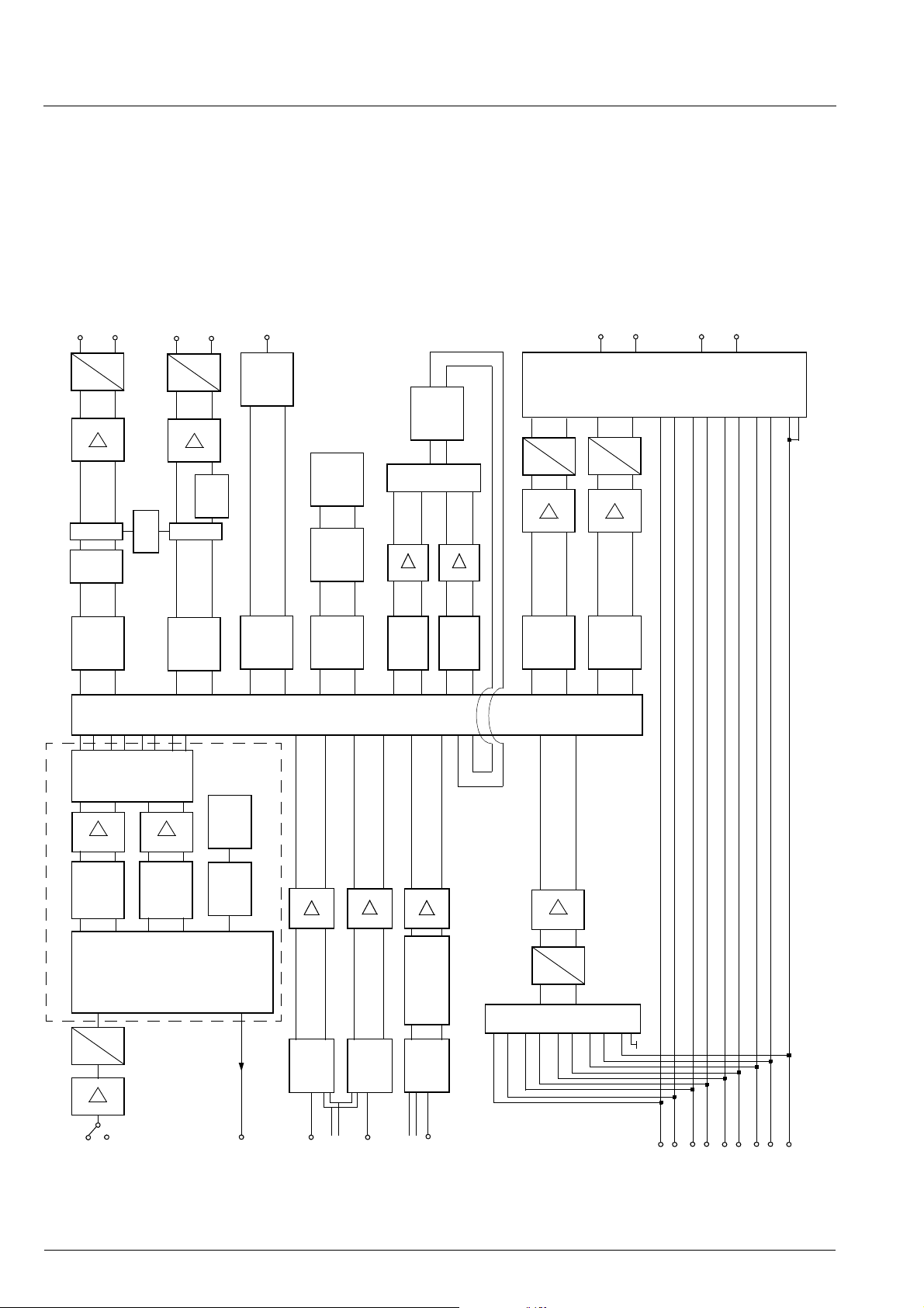
Fig. 2–1 shows a simplified block diagram of the IC.
The block diagram contains all features of the
AVC
DACM_L
DACM_R
A
D
)
(00
Volume
Σ
)
hex
(29
AVC*
)
hex
(08
DACA_L
DACA_R
A
D
hex
Volume
)
hex
(14
Beeper
phasis
Preem-
Σ
)
hex
(09
I2S_DA_OUT
(sync. 48 kHz)
S
2
I
Interface
)
hex
(06
)
hex
(34
)
hex
(0B
*
location is
programmable
Note:
C
2
I
Read
Register
)
(0C
Mix1
hex
Detector
Quasi-Peak
MSP 4458G. Other members of the MSP 44x8G family
do not have the complete set of features, handling only
a subset of the standards (see dashed block in
Fig. 2–1).
)
hex
(3A
scale
)
hex
(38
SC1_OUT_R
SC1_OUT_L
)
hex
(29
AVC*
Σ
)
hex
(3B
Mix2
scale
)
hex
(39
SCART1_L/R
D
Volume
SCART2_L/R
A
A
D
)
hex
(07
)
hex
(40
Volume
)
hex
(0A
)
hex
(41
SC2_OUT_R
SC2_OUT_L
)
hex
SCART Output Select
(13
S
2
Main
Matrix
Channel
Aux
Matrix
Channel
I
Matrix
Channel
Matrix
Channel
Quasi-Peak
Mix1
Channel
Mix2
Matrix
Channel
Matrix
Matrix
Channel
SCART1
Matrix
Channel
SCART2
Source Select
0
1
3
4
5
6
7
15
2
FM/AM
Stereo or A
Stereo or A
Automatic
Soundselect
FM/AM
Deemphasis:
)
hex
(0E
Prescale
Panda1
50/75 µs
DBX/MNR
Stereo or B
)
C
hex
2
I
Read
(10
Standard
and Sound
Register
Detection
)
hex
(16
S1
2
I
Prescale
)
hex
(12
S2
2
I
Prescale
)
hex
(11
S3
2
I
Prescale
)
hex
(0D
SCART
Prescale
NICAM
Prescale
J17
Deemphasis:
D
A
)
SCART DSP Input Select
hex
(13
DEMODULATOR
A2
AM
SAT
EIA-J
BTSC
NICAM
Decoded
Standards:
(incl. Carrier Mute)
FM-Radio
Interpolation
Synchronization /
D
A
S
2
I
Interface
S
2
I
Interface
S
2
I
Interface
AGC
I2S_CL
I2S_WS
ANA_IN2+
ANA_IN1+
Interface
ADR-Bus
I2S_DA_IN1
(sync. 48 kHz)
I2S_DA_IN2
(sync. 48 kHz)
I2S_CL3
I2S_WS3
I2S_DA_IN3
(async. 5-50 kHz)
SC2_IN_L
SC1_IN_L
SC2_IN_R
SC1_IN_R
SC4_IN_L
SC3_IN_L
SC3_IN_R
MONO_IN
SC4_IN_R
8 Micronas
Fig. 2–1: Signal flow block diagram of the MSP 44x8G (input and output names correspond to pin names).

PRELIMINARY DATA SHEET MSP 44x8G
2.2. MSP 44x8G Sound IF Processing
2.2.1. Analog Sound IF Input
The input pins ANA_IN1+, ANA_IN2+, and ANA_IN
offer the possibility to conn ect two different sound IF
(SIF) sources to the MSP 44x8G. The preselected
sound IF signal is fed into an A/D-converter. An analog
automatic gain circuit (AG C) allows a wide range of
input levels. The highpass filters, formed by the coupling capacitors at pins ANA_IN1+ and ANA_IN2+
(see Section 7.3. “Application Circuit” on page 83), are
sufficient in most cases to suppress video components. Some combinations of SAW filters and sound IF
mixer ICs, however, show large picture components on
their outputs. In this case, further filtering is recommended.
2.2.2. Demodulator: Standards and Features
The MSP 44x8G is able to demodulate all TV-sound
standards worldw ide including the digita l NICAM system. Depending on the MSP 44x8G version, the following demodulation modes can be performed:
FM-Satellite Sound: Demodulation of one or two FM
carriers. Processi ng of high-deviation mono or na rrow
bandwidth mono, stereo, or bilingual satellite sound
according to the ASTRA specification.
−
FM-Stereo-Radio: Detection and FM d emodulati on of
the aural carrier resu lting in the MPX si gnal. Detecti on
and evaluation of the pilot carrier and AM demodulation of the (L−R)-carrier.
The demodulator blocks of all MSP 44x8G versions
have identical user interfaces. Even completely different systems like the BTSC and NICAM systems are
controlled the same way. Standards are selected by
means of MSP Standard Cod es. Automatic processes
handle standard detection and identification without
controller interaction. The key features of the
MSP 44x8 G demodu lator blocks are described below.
Standard Selection: The controlling of the de mod ula tor is minimized: All parameters, such as tuning frequencies or filter bandwidth, are adjusted automatically by transmitting one single value to the
STANDARD SELECT reg ister. For all standards, specific MSP standard codes are defined.
A2 Systems: Detection and demodu lation of two separate FM carriers ( FM1 and FM2), demodulation and
evaluation of the identification signal of carrier FM2.
NICAM Systems: (Only possible in the MSP 4418G
and MSP 4458G ). Demodulation and decoding of the
NICAM carrier, detection and demodulation of the analog FM or AM carri er. For D/K-NICAM, the FM carr ier
may have a maximum deviation of 384 kHz.
Very high deviation FM-Mono: Detection and robust
demodulation of on e FM carr ier with a maximum deviation of 540 kHz.
BTSC-Stereo: Detection and FM demodulation of the
aural carrier resulting in the MTS/MPX signal. Detection and evaluation of the pilot carr ier, AM demodulation of the (L−R)-carrier and d etecti on of the SA P subcarrier. Processing of DBX noise reduction or
Micronas Noise Reduction (MNR).
BTSC-Mono + SAP: Detection and FM demodulation
of the aural carrier resulting in the MTS/MPX signal.
Detection and evaluation of the pilot car rier, detection
and FM demodul ation of t he SAP subcar r ier. Processing of DBX noise reduction or Micronas Noise Redu ction (MNR).
Japan Stereo: Detection and FM demodulation of the
aural carrier resulting in the MPX signal. Demodulation
and evaluation of the identification signal and FM
demodulation of the (L−R)-carrier.
Automatic Standar d Detecti on: If the TV sound standard is unknown, the MSP 44x8G can automatically
detect the actual standard, switch to that standard, and
respond the actual MSP standard code.
Automatic Carrier Mute: To prevent noise effects or
FM identification problems in the absence of an FM
carrier, the MSP 44 x8G offers a carrier mute feature,
which is activated automatically if the standard is
selected by means of th e STANDARD SELECT register. If no FM carrier is available at one of the two MSP
demodulator channels, the corresponding demodulator output is muted.
2.2.3. Preprocessing of Demodulator Signals
All demodulated signals must be processed by a
deemphasis filte r and adjusted i n level (analog signals
must also be dematrixed). The co rrect deemphas is filters are already sele cte d by settin g the stan dard i n the
STANDARD SELECT register. The level adjustment
has to be done by means of the FM/A M and NICAM
prescale registers. The necessary dematrix function
depends on the selected sound standard and the
actual broadcasted sound mode (mono, stereo, or
bilingual). It can be manually set by the FM Matrix
Mode register or automatically set by the Automatic
Sound Selection.
Micronas 9
MSP 44x8G PRELIMINARY DATA SHEET
2.2.4. Automatic Sound Select
In the Automatic Sound Select mode, the dematrix
function is automatically selected based on the identification information in the ST ATUS register. No I
2
C interaction is necessary when the broadcasted sound
mode changes (e.g. from mono to stereo).
The demodulator sup ports the identification ch eck by
switching between mono comp atible standards (standards that have the same FM mono c arrier) aut omatically and non-audible. If B/G-FM or B/G-NICAM is
selected, the MSP will switch between these standards. The same action is performed for the standards:
D/K1-FM, D/K2-FM, and D/K-NICAM. Switching is only
done in the absence of any stereo or bilingua l identification. If identification is found, the MSP keeps the
detected standard.
In case of high bit-error rates, the MSP 44x8G automatically falls back from digital NI CAM sound to analog FM or AM mono.
Table 2–1 on page 11 summarizes all actions that take
place when Automatic Sound Select is switched on.
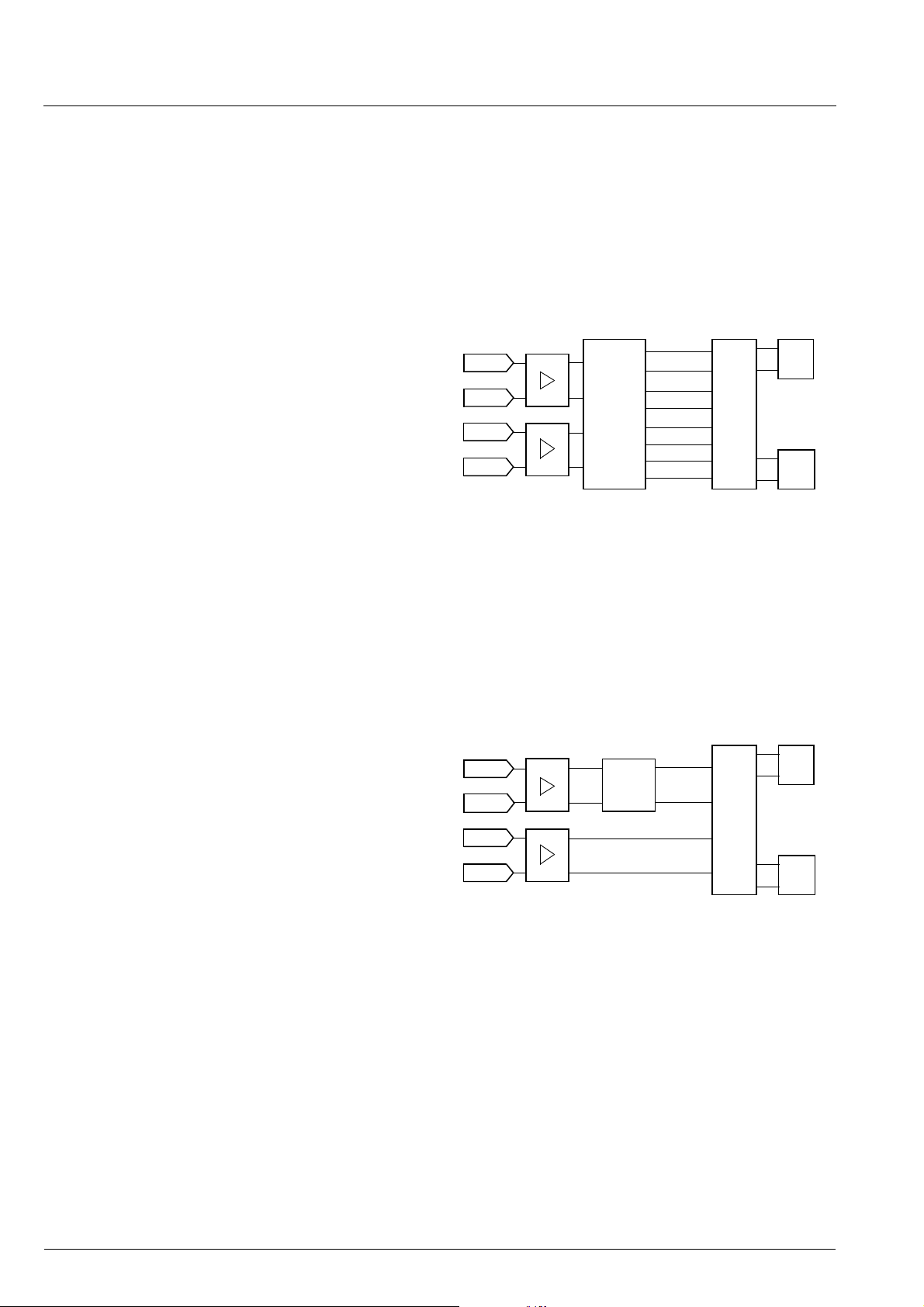
Fig. 2–2 and Table 2–2 show the source channel
assignment of the demodulated signals in case of
Automatic Sound Select mode for all sound standards
(see Section 6.).
Note: The analog primar y input channel contains the
signal of the mono FM/AM c arrie r or the L+R sig nal of
the MPX carrier. The secondary input channel contains the signal of the seco nd FM carr ier, the L−R signal of the MPX carrier, or the SAP signal.
Source Select
LS Ch.
Matrix
Output-Ch.
Matrices must
be set once to
stereo
SC2 Ch.
Matrix
primary
channel
secondary
channel
NICAM A
NICAM
FM/AM
Prescale
NICAM
Prescale
Automatic
Sound
Select
FM/AM
Stereo or A/B
Stereo or A
Stereo or B
0
1
3
4
Fig. 2–2: Source channel assignment of demodulated
signals in Automatic Sound Select Mode
To provide m ore fl exibility, the Automatic Sound Select
block prepares four different source channels of
demodulated sound (Fi g. 2–2). By choosing one of the
four demodulator channels, the p referred sound mode
can be selected by means of the Source Sele ct registers, independent for all MSP-outputs.
The following source chan nels of demodulated sound
are defined:
– “FM/AM” channel: Analog mono sound, stereo if
available. In case of NICAM, analog mono only
(FM or AM mono).
– “Stereo or A/B” channel: Analog or digital mono
sound, stereo if available. In case of bilingual broadcast, it contains both languages A (left) and B
(right).
– “Stereo or A” channel: Analog or digital mono
sound, stereo if available. In case of bilingual broadcast, it contains language A (on left and right).
– “Stereo or B” channel: Analog or digital mono
sound, stereo if available. In case of bilingual broadcast, it contains language B (on left and right).
2.2.5. Manual Mode
Fig. 2–3 shows the source channel assignment of
demodulated signals in ca se of manual mode. If manual mode is required, more information can be found in
Section 6.7. “Demodulator Source Channels in Manual
Mode” on page 80.
Source Select
LS Ch.
Matrix
Output-Ch.
Matrices
must be set
according
the standard
SC2 Ch.
Matrix
primary
channel
secondary
channel
NICAM A
NICAM
FM/AM
Prescale
NICAM
Prescale
FM-Matrix
FM/AM
NICAM
(Stereo or A/B)
0
1
Fig. 2–3: Source channel assignment of demodulated
signals in Manual Mode
10 Micronas
PRELIMINARY DATA SHEET MSP 44x8G
Table 2–1: Performed actions of the Automatic Sound Selection
Selected TV Sound Standard Performed Actions
B/G-FM, D/K-FM, M-Korea,
and M-Japan
B/G-NICAM, L-NICAM, I-NICAM,
and D/K-NICAM
Evaluation of the identification signal and automatic switching to mono, stereo, or bilingual. Preparing four
demodulator source channels according to Table 2–2. Identification is acquired after 500 ms.
Evaluation of NICAM-C-bits and automatic switching to mono, stereo, or bilingual. Preparing four
demodulator source channels according to Table 2–2. NICAM detection is acquired within 150 ms.
In case of bad or no NICAM reception, the MSP switches automatically to FM/AM mono and switches
back to NICAM if possible. A hysteresis prevents periodical switching.
B/G-FM, B/G-NICAM
or
D/K1-FM, D/K2-FM, D/K-NICAM
Automatic searching for stereo/bilingual-identification in case of mono transmission. Automatic and nonaudible changes between Dual-FM and FM-NICAM standards while listening to the basic FM-Mono sound
carrier.
Example: If starting with B/G-FM-Stereo, there will be a periodical alternation to B/G-NICAM in the
absence of FM-Stereo/Bilingual or NICAM-identification. Once an identification is detected, the MSP
keeps the corresponding standard.
BTSC-STEREO, FM Radio Evaluation of the pilot signal and automatic switching to mono or stereo. Preparing four demodulator
source channels according to Table 2–2. Detection of the SAP carrier. Pilot detection is acquired after
200 ms.
BTSC-SAP In the absence of SAP, the MSP switches to BTSC-Stereo if available. If SAP is detected, the MSP
switches automatically to SAP (see Table 2–2).
Table 2–2: Sound modes for the demodulator source channels with Automatic Sound Select
Source Channels in Automatic Sound Select Mode
Broadcasted
Sound
Standard
Selected
MSP Standard
3)
Code
Broadcasted
Sound Mode
FM/AM
(source select: 0)
Stereo or A/B
(source select: 1)
Stereo or A
(source select: 3)
Stereo or B
(source select: 4)
M-Korea
B/G-FM
D/K-FM
M-Japan
B/G-NICAM
L-NICAM
I-NICAM
D/K-NICAM
D/K-NICAM
(with high
deviation FM)
02
1)
03, 08
04, 05, 0B
30
2)
08, 03
09
0A
2)
, 05
0B, 04
0C
1)
MONO Mono Mono Mono Mono
STEREO Stereo Stereo Stereo Stereo
BILINGUAL:
Languages A and B
NICAM not available or
Left = A
Right = B
Left = A
Right = B
AB
analog Mono analog Mono analog Mono analog Mono
error rate too high
2)
MONO analog Mono NICAM Mono NICAM Mono NICAM Mono
STEREO analog Mono NICAM Stereo NICAM Stereo NICAM Stereo
BILINGUAL:
Languages A and B
analog Mono Left = NICAM A
Right = NICAM B
NICAM A NICAM B
20, 21 MONO Mono Mono Mono Mono
STEREO Stereo Stereo Stereo Stereo
20 MONO+SAP Mono Mono Mono Mono
BTSC
21 MONO+SAP Left = Mono
STEREO+SAP Stereo Stereo Stereo Stereo
Right = SAP
STEREO+SAP Left = Mono
Right = SAP
Left = Mono
Right = SAP
Left = Mono
Right = SAP
Mono SAP
Mono SAP
FM Radio 40 MONO Mono Mono Mono Mono
STEREO Stereo Stereo Stereo Stereo
1)
The Automatic Sound Select process will automatically switch to the mono compatible analog standard.
2)
The Automatic Sound Select process will automatically switch to the mono compatible digital standard.
3)
The MSP Standard Codes are defined in Table 3–7 on page 20.
Micronas 11
MSP 44x8G PRELIMINARY DATA SHEET
2.3. Preprocessing for SCART and
2
S Input Signals
I
2
The SCART and I
level by means of the SCART and I
S inputs need only be a djusted in
2
S prescale re gis-
ters.
2.4. Source Selection and Output Channel Matrix
The Source Selec tor makes it possible to di stribute all
source signals (o ne of the demodulator source ch annels, SCART, or I
2
S input) to the desir ed output ch annels (Main, Aux, etc.). All in put and ou tput sig nals ca n
be processed simult aneously. Each source chan nel is
identified by a unique source address.
For each output channel, the output channel matrix
can be set to sound A, sound B, stereo, or mono.
If Automatic Sound Select is on, the output channel
matrix can stay fixed to stereo (transparent) for demodulated signals.
2.4.1. Mixing Unit
2.5. Audio Baseband Processing
2.5.1. Automatic Volume Correction (AVC)
Different sound sources (e.g. terrest rial ch annels, SAT
channels, or SCART) fairly often do not have the same
volume level. Advertisements during movies usually
have a higher volume level than the movie itself. This
results in annoying volume chang es. The AVC solves
this problem by equalizing the volume level.
In the standard confi guration the AVC block is located
in the main channel. Alternatively, the AVC function
can be moved to the mixer path.
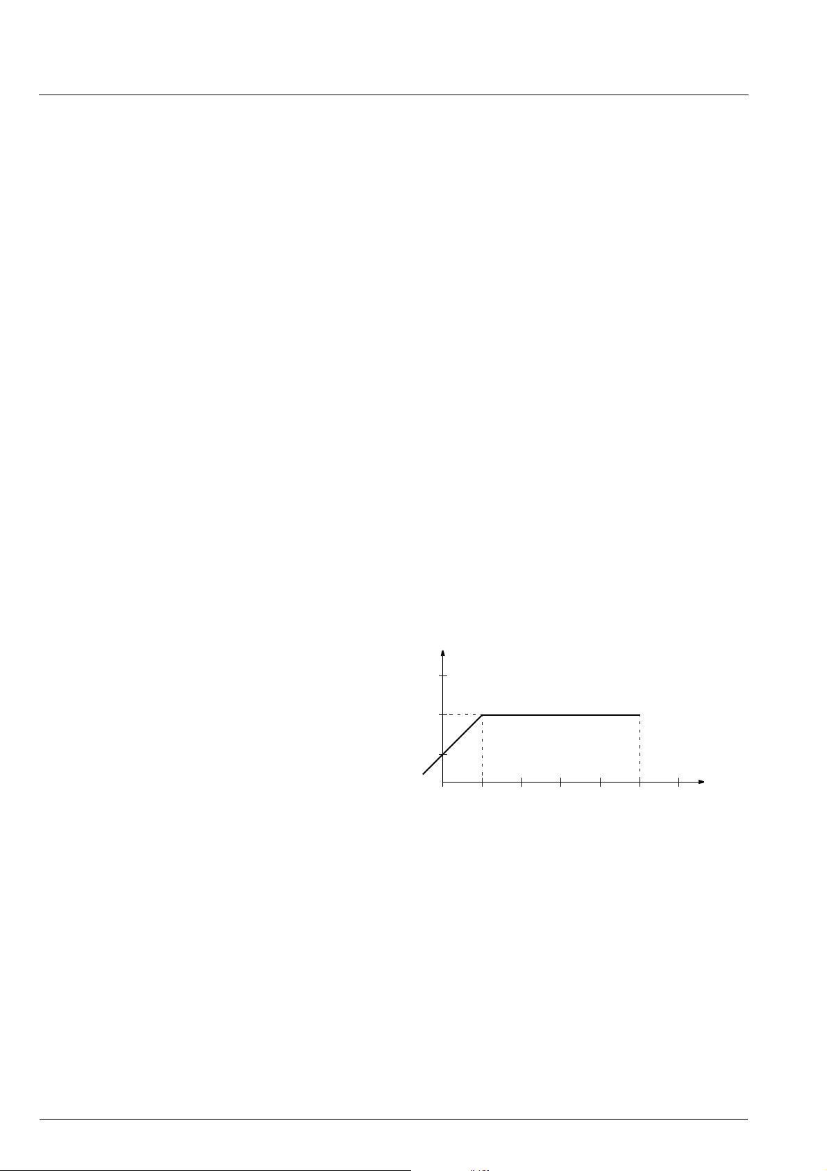
To p revent clipping, the AVC’s gain decreases q uickly
in dynamic boost conditions. To suppress oscillation
effects, the gain increases rather slowly for low-level
inputs. The decay time is programmable by the AVC
register (see page 29).
For input signals ranging from −24 dBr to 0 dBr, the
AVC maintains a fixed output level of −18 dBr. Fig. 2–4
shows the AVC output level versus its input level. For
prescale and volume registers set to 0 dB, a level of
0 dBr corresponds to full scale input/output. This is
Any source can be selected as the input for the two
channels of the Mixi ng unit. The mixer channel matr ices and the scal ing factors can be programmed separately for each channel.
After adding up both channels, the signal is fed back
and is available as source 15 (Mix output) of the
Source Selector.
– SCART input/output 0 dBr = 2.0 V
– Main and Aux output 0 dBr = 1.4 V
rms
rms
output level
[dBr]
12
−
18
−
24
−
30−24−18−12
−
6
−
0
Fig. 2–4: Simplified AVC characteristics
6
+
input level
[dBr]
12 Micronas

PRELIMINARY DATA SHEET MSP 44x8G
2.5.2. Main and Aux Outputs
The Main and Aux output channels ar e adjustable in
volume. A square wave beeper with adjustable frequency and volume can be added to them.
2.5.3. Quasi-Peak Detector
The Quasi-Peak Readout register can be used to read
out the quasi-pe ak level of any input source. The feature is based on following filter time constants:
– attack time: 1.3 ms
– decay time: 37 ms
2.6. SCART Signal Routing
2.6.1. SCART DSP In and SCART Out Select
The SCART DSP Input Select and SCART Output
Select blocks include full matr ix switching facilities. To
design a TV set with four pairs of SCART-inputs and
two pairs of SCART-outputs, no external switching
hardware is required. The switches are controlled by
the ACB user register (see page 31).
2.7.1. Synchronous I
The synchronous I
2
S-Interface(s)
2
S bus interface consists of the
pins:
– I2S_DA_IN1, I2S_DA_IN2/3 (I2S_DA_IN2 in
PQFP80 package):
2
S serial data input, 16, 18...32 bits per sample.
I
– I2S_DA_OUT:
2
S serial data output, 16, 18...32 bits per sample.
I
– I2S_CL:
2
S serial clock.
I
– I2S_WS:
2
S word strobe signal defines the left and right
I
sample.
If the MSP 44x8G serves as the master on the I
2
interface, the clock and word strobe lines are driven by
the MSP. In this mode, only 16, 32 bits per s amp le can
be selected. In slave mode, these lines are input to the
MSP 44x8G and the MSP clock is synchronized to
384 times the I2S_WS rate (48 kHz). NICAM operation
is not possible in slave mode.
2
S timing diagram is shown in Fig. 4–22 on
An I
page 59.
S
2.6.2. Stand-by Mode
If the MSP 44x8G is switched off by first pulling
STANDB YQ l ow and th en (a fter >1µs delay) switching
off the 5-V, but keeping the 8-V power supply ( ‘Stand-
by’- m ode), the SCART switches maintain their position and function. This allows the copying from
selected SCART-inputs to SCART-outputs in the TV
set’s stand-by mode.
In case of power on or starting from stand-by (see
details on the power-up sequence in Fig. 4–20 on
page 56), al l inter na l regi sters except the ACB register
(page 31) are reset to the default configuration (see
Table 3–5 on page 18) . The reset posi tion of the ACB
register becomes active after the fir st I
2
C transmission
into the Baseband Processing part (subaddress
). By transmitting the ACB register first, the reset
12
hex
state can be redefined.
2
S Bus Interfaces
2.7. I
The MSP 44x8G has two kinds of inte rfaces: synchr onous master/slave input/output interfaces running on
48 kHz and an asynchronous slave interface.
2
2.7.2. Asynchronou s I
The asynchronous I
S-Interface
2
S slave interface allows the
reception of digital stereo signals with arbitrary sample
rates from 5 to 50 kHz. The synchronization is performed by means of an adaptive sample rate converter. No oversampling clock is required.
The following pins are used for the asynchron ous I
2
bus interface:
– I2S_WS3 (serves only as input)
– I2S_CL3 (serves only as input)
– I2S_DA_IN2/3 (I2S_DA_IN3 in PQFP80 package).
2
The interface accepts I
S-input streams with M SB first
and with sample widths of 16,18...32 bits. With left/
right alignment and wordstrobe timing polarity, there
are additional paramet ers available for the adaption to
a variety of formats in the I
2
S-CONFIG register (see
page 24).
S
The interfaces accept a variety o f formats with d if ferent
sample width, bit-orientation, and wordstrobe timing.
2
S options are set by means of the MODUS or
All I
2
S_CONFIG register.
I
Micronas 13

MSP 44x8G PRELIMINARY DATA SHEET
2.8. ADR Bus Interface
For the ASTRA Digital Radio System (ADR), the
MSP 4408G, M SP 441 8G, and MSP 4458G performs
preprocessing such as carrier selection and filtering.
Via the 3-line ADR-bus, the resulting signals are transferred to the DRP 3510A coprocessor, where the
source decoding i s performed. To b e prepared for an
upgrade to ADR with an a ddi ti onal D RP board, the following lines of MSP 44x8G should be provided on a
feature connector:
– AUD_CL_OUT
– I2S_DA_IN1, 2, or 3
– I2S_DA_OUT, I2S_WS, I2S_CL
– ADR_CL, ADR_WS, ADR_DA
For more details, please refer to the DRP 3510A data
sheet.
2.9. Digital Control I/O Pins and
Status Change Indication
The static level of the digital input/output pins
D_CTR_I/O_0/1 is switchable between HIGH and
LOW via the I
(see page 31). Thi s enables the controlling of external
hardware switches or other devices via I
2
C-bus by means of the ACB register
2
C-bus.
The digital input/ou tput pins can b e set to high imp edance by means of the MODUS register (see page 23).
In this mode, the pins can be used as input. The current state can be rea d ou t of the S TATUS register (see
page 25).
Optionally, the pin D_CTR_I/O_1 can be used as an
interrupt reque st signal to the co ntrol ler, indicating any
changes in the read register STATUS. This makes polling unnecessary, I
2
C bus interactions are reduced to a
minimum (see “STATUS Register” on page 25 and
“MODUS Register” on page 23).
2.10. Preemphasis
When using the Aux output for feeding an external
modulator, a preemphasis can be applied to the r ight
channel.
The signal is sc aled down by −3 dB. An overmodulation protection is i ncluded in the algo rithm which lim its
the output signal to 0 dBFS. Due to the nature of a preemphasis, its gain at hig h frequencies exceeds 3 dB.
Thus, even with 0 dB input si gnals and p rescal er / volume set to 0 dB, clipping can occur.
There are three modes present: preemphasis off,
50µs, and 75µs. (see Table 3–11on page 29) for the
register settings.
2.11. Clock PLL Oscillator and Crystal Specifications
The MSP 44x8G derives all internal system clocks
from the 18.432 MHz oscillator. In NICAM or in I
2
SSlave mode of the synchronous interface, the clock is
phase-locked to the correspo nding source. Therefore,
it is not possible to use NICAM a nd I
2
S-Slave mode of
the synchronous interface at the same time.
For proper performance, the MSP clock oscillator
requires a 18.432-MHz crystal. Note that for the
phase-locked modes (NICAM, I
tighter tolerance are required. Please note also, that
the asynchronous I
2
S3 slave interface uses a different
2
S-Slave), crystals with
locking mechanism and does not require tighter crystal
tolerances.
Remark on using the crystal:
External cap acitors at each crystal pin to ground are
required. They are necessary for tuning the open-loop
frequency of the internal PLL and for stabilizing the frequency in closed-loop operation. The higher the
capacitors, the lower the resulting clock frequency. The
nominal free running frequency should match
18.432 MHz as closely as possible.
Clock measurements should be done at pin
AUD_CL_OUT. This pin must be acti vated for this purpose (see MODUS register on page 23).
14 Micronas
PRELIMINARY DATA SHEET MSP 44x8G
3. Control Interface
2
C Bus Interface
3.1. I
3.1.1. Device and Subaddresses
2
The MSP 44x8G is controlled via the I
C bus slave
interface.
The IC is selected by transmitting one of the
MSP 44x8G device addr esses. In order to allow up to
three MSP ICs to be connected to a single bus, an
address select pin (ADR_SEL) has been implemented.
With ADR_SEL pulled to high, low, or left open, the
MSP 44x8G r espon ds to different device address es. A
device address pair is defined as a write address and a
read address (see Table 3–1).
Writing is d one by sending the device write address,
followed by the subaddress byte, two address bytes,
and two data bytes. Reading i s done by sending the
write device address, followed by the subaddre ss byte
and two address bytes. Without sending a sto p condition, reading of the addressed data is completed by
sending the device read address and reading two
bytes of data. Refer to Section 3.1.2. for the I
protocol and to Section 3.4. “Programming Tips” on
page 34 for proposals of MSP 44x8G I
2
C bus
2
C telegrams.
See Table 3–2 for a list of available subaddresses.
Due to the internal architecture of the MSP 44x8G, the
IC cannot react immediately to an I
2
C request. The
typical respons e time is abou t 0.3 ms. If the MSP cannot accept another complete byte of data until it has
performed some other function (for example, serv icing
an internal i nterrupt), it wil l hold the clock line I2C_CL
low to force the transmitter into a wait state. The posi tions within a transmissio n where thi s may happen are
indicated by “Wait” in Section 3.1.3. The maximum
wait period of t he MSP dur ing nor mal operation mode
is less than 1 ms.
Internal hardware error handling:
In case of any internal hardware error (e.g. interruption
of the pow e r sup ply o f th e MSP ), t he MS P’s wait period
is extended to 1.8 ms. After thi s time period elapses,
the MSP releases data and clock lines.
Indication and solving of the error status:
To indicate the error status, the remaining acknowledge bits of the actual I
Additionally, bit[14] of CONTROL is set to one. The
MSP can then be r eset via the I
2
C-protocol will be left high.
2
C bus by transmitting
the reset condition to CONTROL.
Indication of reset:
Besides the possibility of hardware reset, the MSP can
also be reset by means of the RE SET bit in the CONTROL register by the controller via I
2
C bus.
Any reset, even caused by an unstable reset line etc.,
is indicated in bit[15] of CONTROL.
2
A general timing diagram of the I
C Bus is shown in
Fig. 4–21 on page 57.
2
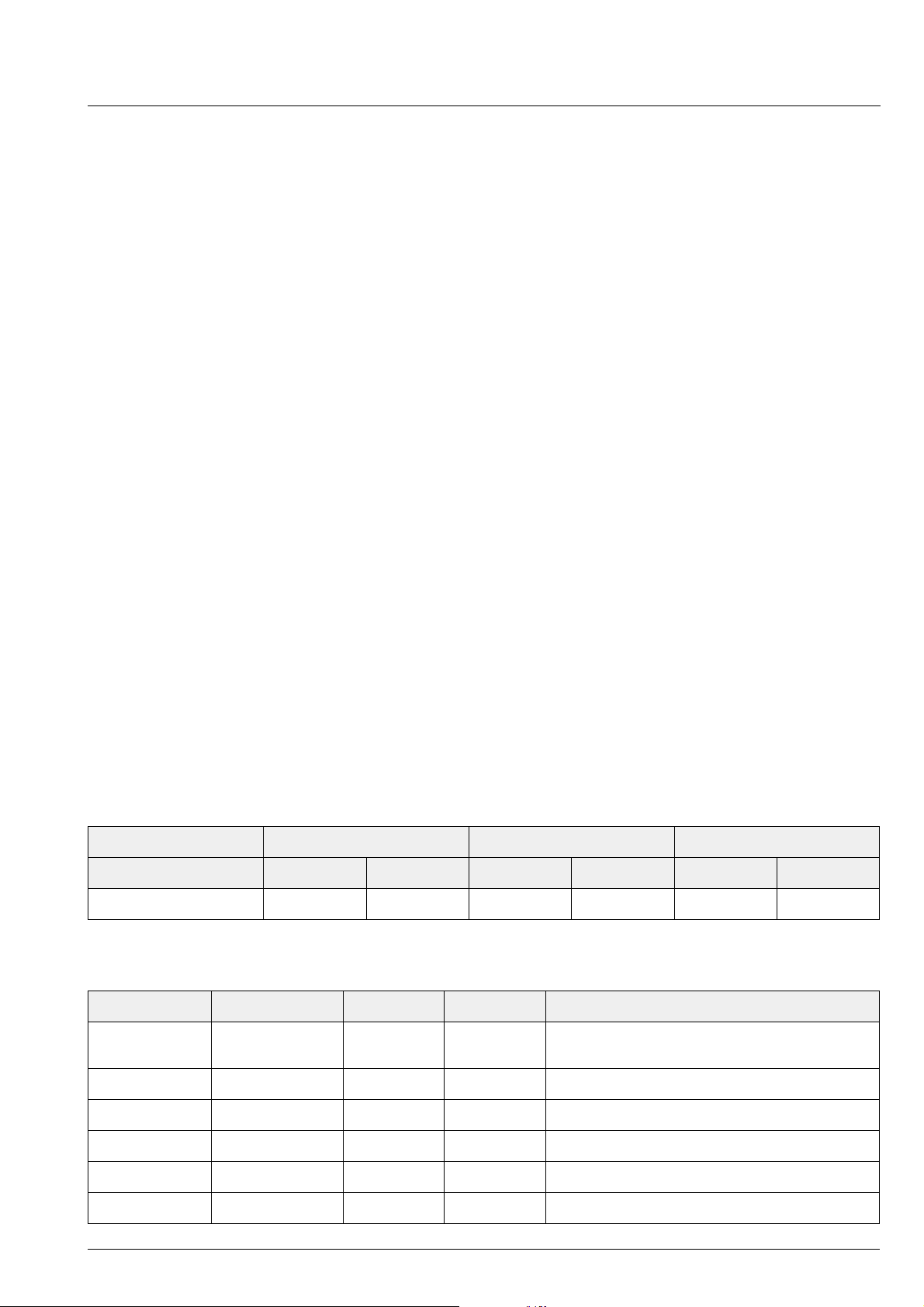
Table 3–1: I
ADR_SEL Low High Left Open
Mode Write Read Write Read Write Read
MSP device address 80
C Bus Device Addresses
hex
81
hex
84
hex
85
hex
88
hex
89
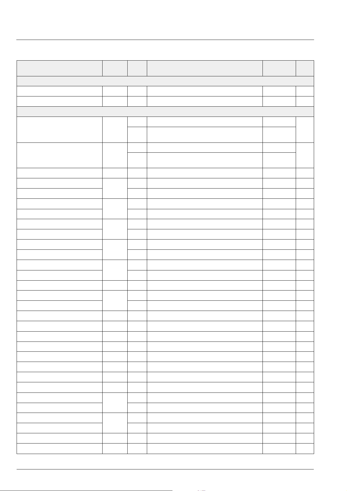
Table 3–2: I2C Bus Subaddresses
Name Binary Value Hex Value Mode Function
CONTROL 0000 0000 00 Read/Write Write: Software reset of MSP (see Table 3–3)
Read: Hardware error status of MSP
TEST 0000 0001 01 Write only for internal use
WR_DEM 0001 0000 10 Write write address demodulator
hex
RD_DEM 0001 0001 11 Write read address demodulator
WR_DSP 0001 0010 12 Write write address DSP
RD_DSP 0001 0011 13 Write read address DSP
Micronas 15
MSP 44x8G PRELIMINARY DATA SHEET
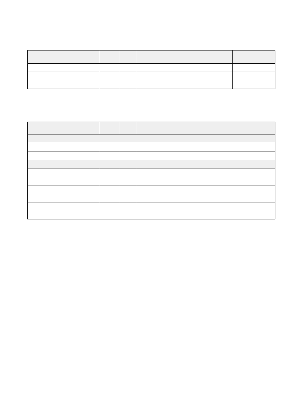
3.1.2. Description of CONTROL Register
Table 3–3: CONTROL as a Write Register
Name Subaddress Bit[15] (MSB) Bits[14:0]
CONTROL 00
hex
1 : RESET
0 : normal
0
Table 3–4: CONTROL as a Read Register
Name Subaddress Bit[15] (MSB) Bit[14] Bits[13:0]
CONTROL 00
hex
Reading of CONTROL will reset the bits[15,14] of CONTROL. After Power-on,
Reset status after last reading of CONTROL:
0 : no reset occured
1 : reset occured
Internal hardware status:
not of interest
0 : no error occured
1 : internal error occured
bit[15] of CONTROL will be set; it must be
read once to be reset.
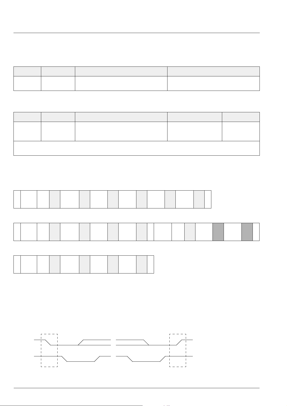
3.1.3. Protocol Description
Write to DSP or Demodulator
Swrite
device
address
Wait
ACK sub-addr ACK addr-byte
high
ACK addr-byte
low
ACK data-byte-
high
ACK data-byte
low
ACK P
Read from DSP or Demodulator
Swrite
device
address
ACK sub-addr ACK addr-byte
Wait
high
ACK addr-byte
low
ACK S read
device
address
Wait
ACK data-byte-
high
ACK data-byte
Write to Control or Test Registers
Swrite
device
address
Wait
Note: S = I
P = I
ACK sub-addr ACK data-byte
2
C-Bus Start Condition from master
2
C-Bus Stop Condition from master
high
ACK data-byte
low
ACK P
ACK = Acknowledge-Bit: LOW on I2C_DA from slave (= MSP, light gray) or master (= controller, dark gray)
NAK = Not Acknowledge-Bit: HIGH on I2C_DA from master (dark gray) to indicate ‘End of Read’
or from MSP indicating internal error state
2
Wait = I
I2C_DA
C-Clock line is held low, while the MSP is processing the I2C command.
1
0
S P
I2C_CL
NAK P
low
2
Fig. 3–1: I
C bus protocol (MSB first; data must be stable while clock is high)
16 Micronas

PRELIMINARY DATA SHEET MSP 44x8G
3.1.4. Proposals for General MSP 44x8G
2
C Telegrams
I
3.1.4.1. Symbols
daw write device address (80
dar read device address (81
hex
hex
, 85
hex
hex
or 88
or 89
hex
hex
)
)
, 84
< Start Condition
> Stop Condition
aa Address Byte
dd Data Byte
3.1.4.2. Write Telegrams
<daw 00 d0 00> write to CONTROL register
<daw 10 aa aa dd dd> write data into demodulator
<daw 12 aa aa dd dd> write data into DSP
3.1.4.3. Read Telegrams
<daw 11 aa aa <dar dd dd> read data from demodulator
<daw 13 aa aa <dar dd dd> read data from DSP
3.1.4.4. Examples
3.2. Start-Up Sequence:
Power-Up and I
2
C Controlling
After POWER ON or RESET (see Fig. 4–20 on
page 56), the IC is in an inactive state. All registers are
in the reset position (seeTable 3–5 and Table 3–6), the
analog outputs a re muted. T he con troll er h as to in itial ize all registers for whic h a non-default setting is necessary.
3.3. MSP 44x8G Programming Interface
3.3.1. User Registers Overview
The MSP 44x 8G is control led by means of user registers. The complete lis t of all user registers is given in
the following tables. The regist ers are parti tioned into
the demodulator s ection (sub addre ss 10
for reading) and the baseband proc essing sec-
11
hex
tions (subaddress 12
for writing, 13
hex
Write and r ead registers are 16-bit wide, whereby the
MSB is denoted bit[15]. Transmissions via I
for writing,
hex
for reading).
hex
2
C bus have
to take place in 16-bit words (two byte transfers, with the
most significant byte transferred first). All write register s,
except the demodulator write registers, are readable.
<80 00 80 00> RESET MSP statically
<80 00 00 00> Clear RESET
<80 10 00 20 00 03> Set demodulator to stand. 03
<80 11 02 00 <81 dd dd> Read STATUS
<80 12 00 08 01 20> Set main channel
source to NICAM and
Matrix to STEREO
hex
More examples of typical application protocols are
listed in Section 3.4. “Programming Tips” on page 34.
Unused parts of the 16-bit write registers must be zero.
Addresses not given in this table must not be written.
An overview of all MSP 44x8G write registers is shown
in Table 3–5; all read registers are given in Table 3–6.
Additional read and write registers, together with a
detailed descr ip tion of the manual mode, can be found
in the “Appendix B: Manual Mode” on page 73.
Micronas 17
MSP 44x8G PRELIMINARY DATA SHEET
Table 3–5: List of MSP 44x8G Write Registers
Write Register Address
(hex)
I2C Subaddress = 10
; Registers are
hex
not
Bits Description and Adjustable Range Reset See
Page
readable
STANDARD SELECT 00 20 [15:0] Initial Programming of complete Demodulator 00 00 21
2
MODUS 00 30 [15:0] Demodulator, Automatic and I
I2C Subaddress = 12
; Registers are
hex
all
readable by using I2C Subaddress = 13
hex
S options 00 00 22
Volume main channel 00 00 [15:8] [+12 dB ... −114 dB, MUTE] MUTE 29
[7:5]
[4:0]
1/8 dB Steps
must be set to 0
000
bin
00000
bin
Volume Aux channel 00 06 [15:8] [+12 dB ... −114 dB, MUTE] MUTE 29
[7:5]
[4:0]
1/8 dB Steps
must be set to 0
000
bin
00000
bin
Volume SCART1 output channel 00 07 [15:8] [+12 dB ... −114 dB, MUTE] MUTE 30
2
Main source select 00 08 [15:8] [ FM/AM, NICAM, SCART, I
S1..3, Mix output] FM/AM 28
Main channel matrix [7:0] [SOUNDA, SOUNDB, STEREO, MONO] SOUNDA 28
2
Aux source select 00 09 [15:8] [ FM/A M, NICAM , SC ART, I
S1..3, Mix output] FM/AM 28
Aux channel matrix [7:0] [SOUNDA, SOUNDB, STEREO, MONO] SOUNDA 28
2
SCART1 source select 00 0A [15:8] [FM/AM, NICAM, SCART, I
S1..3, Mix output] FM/AM 28
SCART1 channel matrix [7:0] [SOUNDA, SOUNDB, STEREO, MONO] SOUNDA 28
2
S source select 00 0B [15:8] [FM/AM, NICAM, SCART, I2S1..3, Mix output] FM/AM 28
I
2
S channel matrix [7:0] [SOUNDA, SOUNDB, STEREO, MONO] SOUNDA 28
I
2
Quasi-peak detector source select 00 0C [15:8] [FM/AM, NICAM, SCART, I
S1..3, Mix output] FM /AM 28
Quasi-peak detector matrix [7:0] [SOUNDA, SOUNDB, STEREO, MONO] SOUNDA 28
Prescale SCART input 00 0D [15:8] [00
Prescale FM/AM 00 0E [15:8] [00
hex
hex
... 7F
... 7F
]00
hex
]00
hex
hex
hex
27
26
FM matrix [7:0] [NO_MAT, GSTEREO, KSTEREO] NO_MAT 27
Prescale NICAM 00 10 [15:8] [00
2
Prescale I
Prescale I
S3 00 11 [15:8] [00
2
S2 00 12 [15:8] [00
hex
hex
hex
... 7F
... 7F
... 7F
SCART switches and D_CTR_I/O 00 13 [15:0] Bits [15:0] 00
Beeper 00 14 [15:0] [00
2
Prescale I
S1 00 16 [15:8] [00
hex
hex
... 7F
... 7F
]00
hex
]10
hex
]10
hex
]/[00
hex
hex
... 7F
hex
]10
] 00/00
hex
hex
hex
hex
hex
hex
hex
27
27
27
31
32
27
AVC: Aut omatic Volume Correction 00 29 [15:8] [off, on, decay time] off 29
Aux Preemphasis on right channel 00 34 [15:8] [ OFF, 50µs, 75µs] OFF 29
2
Mix1 source select 00 38 [15:8] [FM/AM, NICAM, SCART, I
S1..3, Mix output] FM/AM 28
Mix1 channel matrix [7:0] [SOUNDA, SOUNDB, STEREO, MONO] SOUNDA 28
2
Mix2 source select 00 39 [15:8] [FM/AM, NICAM, SCART, I
S1..3, Mix output] FM/AM 28
Mix2 channel matrix [7:0] [SOUNDA, SOUNDB, STEREO, MONO] SOUNDA 28
Scale Mix1 00 3A [15:8] [00
Scale Mix2 00 3B [15:8] [00
hex
hex
... 7F
... 7F
]00
hex
]00
hex
hex
hex
32
32
18 Micronas
PRELIMINARY DATA SHEET MSP 44x8G
Table 3–5: Lis t of MSP 44x8G Write Register s, co ntinue d
Write Register Address
Bits Descript ion and Adjustable Range Reset See
(hex)
Volume SCAR T2 output channel 00 40 [15:8] [+12 dB ... −114 dB, MUTE] 00
2
SCART2 source select 00 41 [15:8] [FM/AM, NICAM, SCART, I
S1..3, Mix output] FM 28
hex
SCART2 channel matrix [7:0] [SOUNDA, SOUNDB, STEREO, MONO] SOUNDA 28
Table 3–6: List of MSP 44x8G Read Registers
Read Register Address
(hex)
I2C Subaddress = 11
; Registers are
hex
not
STANDARD RESULT 00 7E [15:0] Result of Automatic Standard Detection (see Table 3–8) 25
STATUS 02 00 [15:0] Monitoring of settings e.g. Stereo, Mono, Mute, D_CTR_I/O etc. . 25
I2C Subaddress = 13
; Registers are
hex
not
writable
Quasi peak readout left 00 19 [15:0] [00
Quasi peak readout right 00 1A [15:0] [00
MSP hardware version code 00 1E [15:8] [00
MSP major revision code [7:0] [00
MSP product code 00 1F [15:8] [00
MSP ROM version code [7:0] [00
Bits Descript ion and Adjustable Range See
writable
... 7FFF
hex
... 7FFF
hex
... FF
hex
... FF
hex
... FF
hex
... FF
hex
]16 bit two’s complement 33
hex
]16 bit two’s complement 33
hex
]33
hex
]33
hex
]33
hex
]33
hex
Page
30
Page
Micronas 19
MSP 44x8G PRELIMINARY DATA SHEET
3.3.2. Description of User Registers
Table 3–7: Standard Codes for STANDARD SELECT register
MSP Standard
Code
(Data in hex)
TV Sound Standard Sound Carrier
Frequencies in
MHz
MSP 44x8G
Version
Automatic Standard Detection
00 01 Start Automatic Standard Detection all
Standard Selection
00 02 M-Dual FM-Stereo 4.5/4.724212 4408, 4418, 4448,
4458
00 03 B/G-Dual FM-Stereo
00 04 D/K1-Dual FM-Ster eo
00 05 D/K2-Dual FM-Ster eo
1)
2)
2)
00 06 D/K-FM-Mono with HDEV3
Automatic Standard Detection, for China
HDEV3
3)
SAT-Mono (i.e. Eutelsat,
3)
, not detectable by
5.5/5.7421875 4408, 4418, 4458
6.5/6.2578125
6.5/6.7421875
6.5
see Table 6–12)
00 07 D/K3-Dual FM-Stereo 6.5/5.7421875 4408, 4418, 4458
00 08 B/G-NICAM-FM
1)
5.5/5.85 4418, 4458
00 09 L-NICAM-AM 6.5/5.85
00 0A I-NICAM-FM 6.0/6.552
00 0B D/K-NICAM-FM
2)
00 0C D/K-NICAM-FM with HDEV2
4)
, not detectable by
6.5/5.85
6.5/5.85
Automatic Standard Detection, for China
00 0D D/K-NICAM-FM with HDEV3
, not detectable by
6.5/5.85 4418, 4458
3)
Automatic Standard Detection, for China
00 20 BTSC-Stereo 4.5 4438, 4448, 4458
00 21 BTSC-Mono + SAP
00 30 EIA-J Japan Stereo 4.5 4448, 4458
00 40 FM-Stereo Radio 10.7 4438, 4448, 4458
00 50 SAT-Mono (see Table6–12) 6.5 4408, 4418, 4458
00 51 SAT-Stereo (see Table 6–12) 7.02/7.20 4408, 4418, 4458
00 60 SAT ADR (Astra Digital Radio) 6.12 4408, 4418, 4458
1)
In case of Automatic Sound Select, the B/G-codes 3
2)
In case of Automatic Sound Select, the D/K-codes 4
3)
HDEV3: Max. FM deviation must not exceed 540 kHz
4)
HDEV2: Max. FM deviation must not exceed 360 kHz
hex
hex
and 8
, 5
hex
are equivalent.
hex
, 7
and B
hex
are equivalent.
hex
20 Micronas
PRELIMINARY DATA SHEET MSP 44x8G
3.3.2.1. STANDARD SELECT Register
The TV sound standard of the MSP 44x8G demodulator is determined by the STANDARD SELECT register.
There are two ways to use the STANDARD SELECT
register:
– Setting up the demodulator for a TV sound standard
by sending the corresponding standard code with a
single I
2
C-Bus transmission.
– Starting the Automatic Standard Detection for ter-
restrial TV s tandards. This is the most comfor table
way to set up the demodulator. Within 0.5 s, the
detection and set-up of the actual TV sound standard is performed. The detected standard can be
read out of the STANDARD RESULT register by the
control process or. This feature is recommende d for
the primary set-up of a TV set. Output s should be
muted during Automatic Standard Detection.
The Standard Codes are listed in Table 3–7.
Selecting a TV sound standard via the STANDARD
SELECT register initializes the demodulator. This
includes: AGC, tuning frequency, band-pass filters,
demodulation mode (FM, AM, or NICAM), carrier
mute, deemphasis, and identification mode.
If a present sound sta nda rd is im pos s ible for a specifi c
MSP version, it switches to the analog m ono soun d of
this standard. In that case, stereo or bi lingual processing will not be possible.
As long as the STANDARD RESULT register contains
a value greater than 07 FF
, the Automatic Standard
hex
Detection is still active. During this period, the MODUS
and STA NDARD SELECT regi ste r must not be written.
The STATUS regist er will be updated when the Automatic Standard Detection has finished.
If a present sound sta nda rd is im pos sible for a spec ifi c
MSP version, it detects and switches to the analog
mono sound of this standard.
Example:
The MSPs 4438G and 4448G will detect a B/G-NICAM
signal as stand ard 3 and will switch to t he analog FMMono sound.
Table 3–8: Results of the Automatic Standard
Detection
Broadcasted Sound
Standard
Automatic Standard
Detection could not
find a sound standard
B/G-FM 0003
B/G-NICAM 0008
I 000A
STANDARD RESULT Register
Read 007E
0000
hex
hex
hex
hex
hex
For a complete setup of the TV sound processing from
analog IF input to the source selection, the following
transmissions are necess ary : MODUS register, STANDARD SELECT register, prescale values, FM matrix.
Note: The FM matrix is set automatically if Automatic
Sound Select is active (MODUS[0]=1). In this case, the
FM matrix will b e i nit ial ized w ith “S ou nd A Mo no”. Du ring operation, the FM matrix will be automatically
selected according to the actual identif ication information.
3.3.2.2. STANDARD RESULT Register
If Automatic Standard Detection is selected in the
STANDARD SELEC T register, status and res ult of the
Automatic Standard Detection process can be read out
of the STANDARD RESULT register. The possible
results are based on the mentioned Standard Code
and are listed in Table 3–8.
In cases where no s ound st andard h as been detected
(no standard present , too much noise, strong interferers, etc.) the STANDARD RESULT register contains
00 00
. In that case, the controller has to start further
hex
actions (for example, set the standard according to a
preference list or by manual input).
FM-Radio 0040
M-FM
EIA-J
BTSC
L-AM
D/K1
D/K2
L-NICAM
D/K-NICAM
Automatic Standard
Detection still activ e
0002
0020
0030
0009
0004
0009
000B
>07FF
hex
(if MODUS[14,13]=00)
hex
(if MODUS[14,13]=01)
hex
(if MODUS[14,13]=10)
hex
(if MODUS[12]=0)
hex
(if MODUS[12]=1)
hex
(if MODUS[12]=0)
hex
(if MODUS[12]=1)
hex
hex
Micronas 21

MSP 44x8G PRELIMINARY DATA SHEET
3.3.2.3. Write Registers on I2C Subaddress 10
Table 3–9: Write Registers on I2C Subaddress 10
Register
Function Name
Address
STANDARD SELECTION
00 20
hex
STANDARD SELECTION Register
Defines TV Sound or FM-Radio Standard
bit[15:0] 00 01
00 02
start Automatic Standard Detection
hex
Standard Codes (see Table 3–7))
hex
...
hex
00 60
hex
hex
STANDARD_SEL
22 Micronas

PRELIMINARY DATA SHEET MSP 44x8G
Table 3–9: Write Registers on I
Register
Function Name
Address
MODUS
00 30
hex
MODUS Register
General MSP 44x8G Options
bit[15] 0 undefined, must be 0
bit[14:13] detected 4.5 MHz carrier is interpreted as:
0 standard M (Korea)
1 standard M (BTSC)
2 standard M (Japan)
3 Carrier at 4.5 MHz is ignored (chroma carrier)
Preference in Automatic Standard Detection:
bit[12] detected 6.5 MHz carrier is interpreted as:
0 standard L (SECAM)
1 standard D/K1, D/K2, or D/K NICAM
bit[11:9] 0 undefined, must be 0
bit[8] 0/1 ANA_IN_1+/ANA_IN_2+;
2
C Subaddress 10
, continued
hex
select analog sound IF input pin
MODUS
1)
1)
bit[7] 0/1 active/tristate state of audio clock output pin
AUD_CL_OUT
bit[6] word strobe alignment (synchronous I
0 WS changes at data word boundary
1 WS changes one clock cycle in advance
bit[5] 0/1 master/slave mode of I
(= Master) in case of NICAM mode)
bit[4] 0/1 active/tristate state of I
bit[3] state of digital output pins D_CTR_I/O_0 and _1
0 active: D_CTR_I/O_0 and _1 are output pins
(can be set by means of the ACB register.
see also: MODUS[1])
1 tristate: D_CTR_I/O_0 and _1 are input pins
(level can be read out of STATUS[4,3])
bit[2] 0 undefined, must be 0
bit[1] 0/1 disable/enable STATUS change indication by means of
the digital I/O pin D_CTR_I/O_1
Necessary condition: MODUS[3] = 0 (active)
bit[0] 0/1 off/on: Automatic Sound Select
1)
Valid at the next start of Automatic Standard Detection.
2
S)
2
S interface (must be set to 0
2
S output pins
Micronas 23

MSP 44x8G PRELIMINARY DATA SHEET
Table 3–9: Write Registers on I
Register
Function Name
Address
0040
hex
I2S Configuration Register
(not mentioned bit combinations must not be used)
bit[15:12] 0 undefined, must be set to 0
bit[11] I
0 left aligned
1 right aligned
bit[10] word strobe polarity (I
1 0 = right, 1 = left
0 1 = right, 0 = left
bit[9] word strobe alignment (asynchronous I
0 WS changes at data word boundary
1 WS changes one clock cycle in advance
bit[8:2] 0 undefined, must be set to 0
bit[1:0] I2S_CL frequency and I
00 2 * 16Bit (1.536MHz Clk)
01 2 * 32Bit (3.072MHz Clk)
1x undefined, must not be used
2
C Subaddress 10
2
S Data alignment (I2S_3)
, continued
hex
2
S_3)
2
S_3)
2
S_DA_OUT sample length
I2S_CONFIG
24 Micronas

PRELIMINARY DATA SHEET MSP 44x8G
3.3.2.4. Read Registers on I2C Subaddress 11
hex
Table 3–10: Read Registers on I2C Subaddress 11
Register
Function Name
Address
STANDARD RESULT
00 7E
hex
STANDARD RESULT Register
Readback of the detected TV Sound or FM-Radio Standard
bit[15:0] 00 00
Automatic Standard Detection could not find
hex
a sound standard
00 02
MSP Standard Codes (see Table 3–8)
hex
...
00 40
>07 FF
hex
Automatic Standard Detection still active
hex
STATUS
02 00
hex
STATUS Register
Contains all user relevant internal information about the status of the MSP
hex
STANDARD_RES
STATUS
bit[15:10] undefined
bit[8] 0/1 “1” indicates bilingual sound mode or SAP present
bit[7] 0/1 “1” indicates independent mono sound
(only for NICAM on MSP 4418G and MSP 4458G)
bit[6] 0/1 mono/stereo indication
bit[5,9] 00 analog sound standard (FM or AM) active
01 this pattern will not occur
10 digital sound (NICAM) available (MSP 4418G and
MSP 4458G only)
11 bad receptio n co nd itio n o f di gi ta l so un d (N ICAM ) du e to :
a. high error rate
b. unimplemented sound code
c. data transmission only
bit[4] 0/1 low/high level of digital I/O pin D_CTR_I/O_1
bit[3] 0/1 low/high level of digital I/O pin D_CTR_I/O_0
bit[2] 0 detected secondary carrier (2nd A2 or SAP carrier)
1 no secondary carrier detected
bit[1] 0 detected primary carrier (Mono or MPX carrier)
1 no primary carrier detected
bit[0] undefined
If STATUS change indication is activated by means of MODUS[1]: Each
change in the ST ATUS register sets the digital I/O pin D_CTR_I/O_1 to high
level. Reading the STATUS register resets D_CTR_I/O_1.
Micronas 25

MSP 44x8G PRELIMINARY DATA SHEET
3.3.2.5. Write Registers on I2C Subaddress 12
hex
Table 3–11: Write Registers on I2C Subaddress 12
Register
Function Name
Address
PREPROCESSING
00 0E
hex
FM/AM Prescale
bit[15:8] 00
7F
00
hex
hex
hex
... Defines the input prescale gain for the demodulated FM or
AM signal
off (RESET condition)
For all FM modes except satellite FM, the combinations of prescale value and
FM deviation listed below lead to internal full scale.
FM mode
bit[15:8] 7F
48
30
24
18
13
hex
hex
hex
hex
hex
hex
28 kHz FM deviation
50 kHz FM deviation
75 kHz FM deviation
100 kHz FM deviation
150 kHz FM deviation
180 kHz FM deviation (limit)
hex
PRE_FM
FM high deviation mode (HDEV2, MSP Standard Code = C
bit[15:8] 30
14
hex
hex
150 kHz FM deviation
360 kHz FM deviation (limit)
hex
)
FM very high deviation mode (HDEV3, MSP Standard Code = 6)
bit[15:8] 20
1A
hex
hex
450 kHz FM deviation
540 kHz FM deviation (limit)
Satellite FM with adaptive deemphasis
bit[15:8] 10
hex
recommendation
AM mode (MSP Standard Code = 9)
bit[15:8] 7C
hex
recommendation for SIF input levels from
0.1 V
to 0.8 V
pp
pp
(Due to the AGC switched on, the AM-output level remains
stable and independent of the actual SIF-level in the mentioned input range)
26 Micronas
 Loading...