

Page 1
MICRON
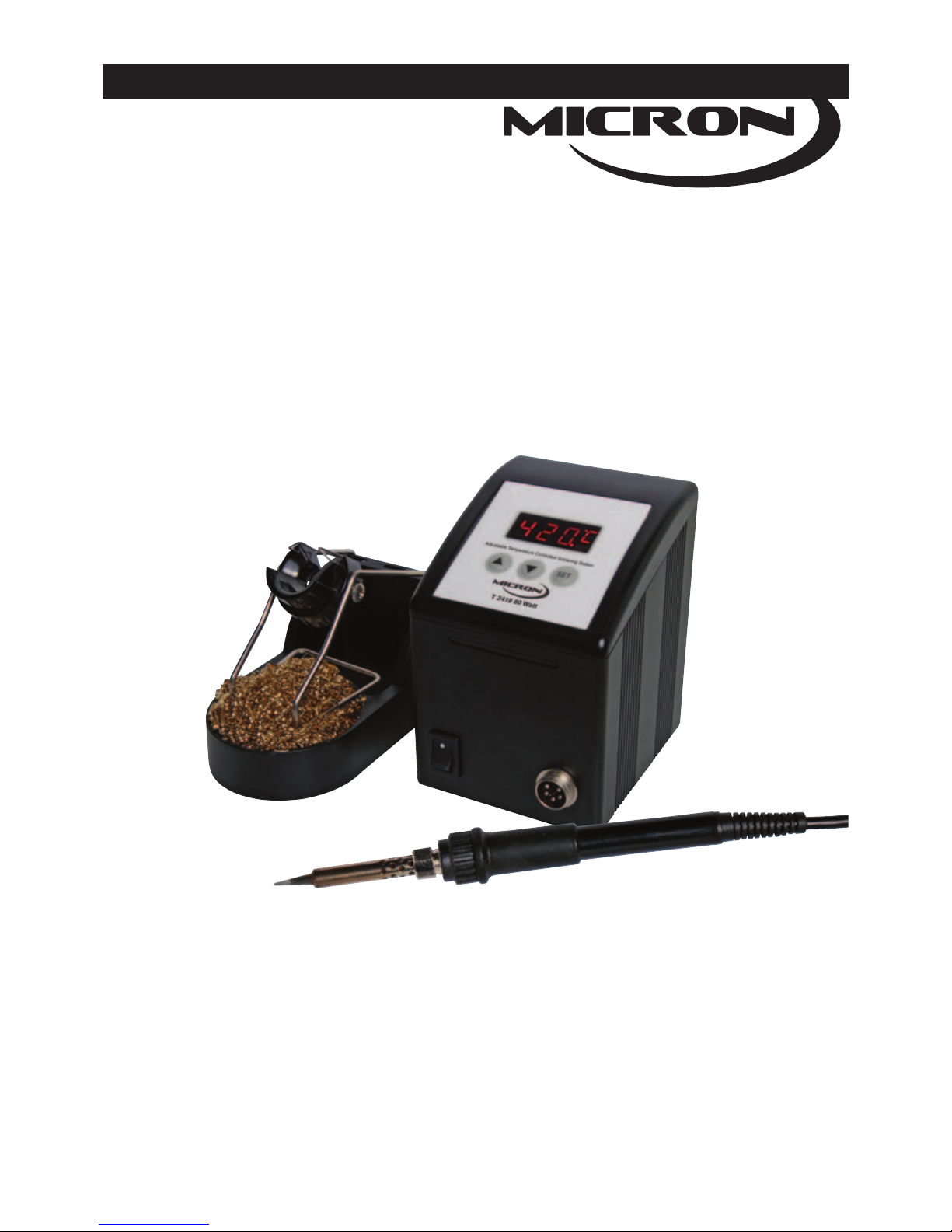
T 2418 Temperature Controlled
Soldering Station
Operating Instructions
• LED display • Simple push button operation
• Silicone burn proof iron lead
• Free standing iron holder with tip cleaner
• Temperature adjustable • Temperature correction adjustment
• Suitable for ROHS compliant soldering
• ESD safe and spike free circuitry • Grounding socket
Page 2

MICRON
Overview
Thank you for purchasing the T 2418 soldering station – a great solution for your soldering equipment needs!
We believe that you will be more than satisfied with the many features and the versatility of your new soldering
station. Please carefully read the instruction manual prior to operation to maximize the advantages of using
your new soldering station.
WARNING: This appliance is not intended for use by children or infirm persons without assistance or
supervision if their physical, sensory or mental capabilities prevent them from using it safely. Children should
be supervised to ensure that they do not play with the appliance. Failure to observe this safety regulation could
result in a risk to life and limb. The manufacturer or supplier shall not be liable for damage resulting from
misuse of the unit or unauthorised alterations.
Caution:
DO NOT WORK ON LIVE CIRCUITS
• Before working on any mains powered equipment, make sure that it is turned off, and the mains plug is
removed from the power point. You must not undertake work on live parts.
DO NOT USE IF DAMAGED
• If the power lead becomes damaged or the soldering station becomes faulty, discontinue use immediately.
Caution: Soldering irons operate at high temperatures and can easily burn the skin and/or objects. Do
not touch the tip and heater at any time and keep it a safe distance from flammable materials while
the unit is on, or while cooling after switching off. Please allow a sufficient time for it to cool before
changing tips. For your health, do not inhale solder fumes.
Product Description:
The T 2418 digital readout, electronically temperature controlled soldering station has been designed to meet
the present and future soldering needs of the electronic production industry, hobbyist and student.
The unit has a slender soldering iron pencil design with a burn-proof silicone cord and a comfortable rubber
grip that prevents operator fatigue.
The electronic circuitry enables the user to adjust the temperature from 200°C (392°F) to 480°C (896°F)
without changing the tip. The temperature is maintained to within ±3°C of its idling temperature by a
thermocouple sensor placed in the head of the heating element. The T 2418 incorporates sensor failure
detection, where, if the sensor circuit fails the display will read “S-E” and power will automatically be cut off to
the heater. If the heater circuit fails the display will read H-E and power to the heater will automatically be cut
off. Also the temperature can be locked by a “temperature lockout” code that is convenient for production line
management.
The electronic “ZERO VOLTAGE“ switching protects voltage and current sensitive components, such as “CMOS”
devices against transient voltage spikes, that can be caused by switching the power or heater on/off or other
environmental conditions.
The specifically designed heater brings the temperature up to approximately 480°C (full setting) in about 45
seconds. This results in very fast heat-up, instant recovery, and superior heat transmission.
The tip is grounded through the power unit to ensure leakage of less than 0.4 millivolts, and a wide selection of
long-lasting, nickel/chrome plated and pre-tinned tips are available to meet all your soldering needs.
1
Page 3
MICRON
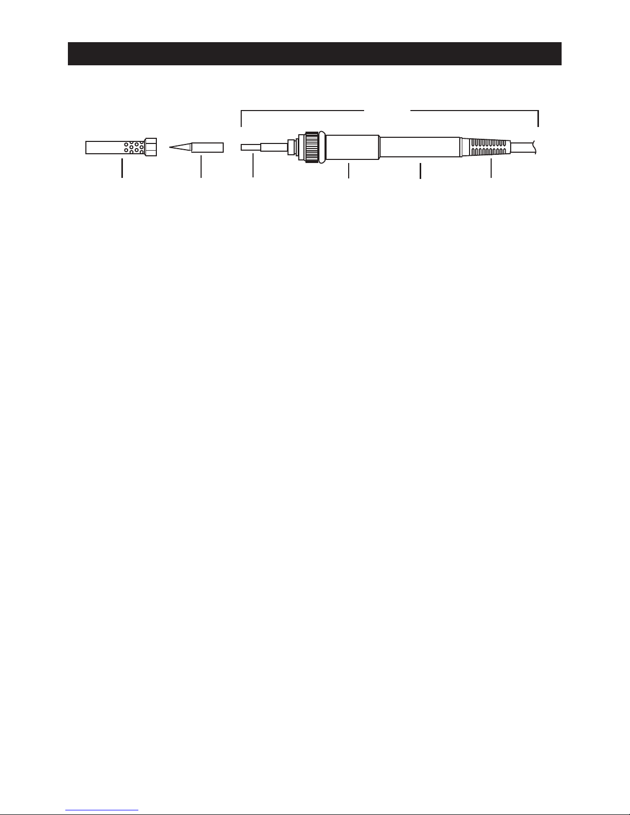
Barrel + Nut Tip Ceramic Rubber Handle Bending
(T-2442B) (T 2434) Heater Collar Guard
Complete
T-2418A
Handle Exploded View Diagram
The handle suits tips:
T 2434 0.8mm conical (supplied)
T 2435 1.6mm chisel (sold separately)
T 2436 3.2mm chisel (sold separately)
6
Page 4

MICRON
should only be used to tighten the nut to avoid burning your fingers and care should be taken not to overtighten as this would damage the element. The solder tips supplied are nickel/chrome plated pure copper and
if used properly will give a long life.
Remember to tin all new tips before use. Refer to item 3 in the Operating Instructions
1. Always keep tips tinned before returning to the holder, switching off or storing for any period of time. Wipe
only before using.
2. Don’t keep iron set at a high temperature for long periods of time as this will break down the surfaces of the
tip.
3. Don’t put any excessive pressure on a tip or rub a tip on a joint. It does not improve the heat transfer but
only damages the tip.
4. Never clean the tip with abrasive materials or a file.
5. Don’t use a flux containing chloride or acid. Use only rosin or activated resin fluxes.
6. If any oxide does form, it can be cleaned by lightly rubbing with a 600-800 grit emery cloth, or cleaning with
isopropyl alcohol or equivalent. After cleaning, wet the tip and wrap rosin-core solder completely around the
newly exposed surfaces.
GENERAL CLEANING
The outer cover of the iron and station may be cleaned with a damp cloth using small amounts of liquid
detergent. Never submerse the unit in liquid or allow any liquid to enter the case of the station. Never use any
solvent to clean the case.
IMPORTANT SERVICE NOTE:
There are no user serviceable parts inside the unit. Do not open the unit. If the fuse blows, only replace with an
equivalent fuse.
If the iron or station should become faulty or, for some reason not operate normally, the system should be
returned to the service department of your authorised dealer or service agent, or a similarly qualified person in
order to avoid a hazard.
T 2418 Specifications
Input: ..................................................................................................................................220-240Va.c. 50Hz
Heater voltage:......................................................................................................................................32V a.c.
Heater element: ....................................................................................................................................Ceramic
Heater insulation: ................................................................................................................................<100MΩ
Nominal power: ..........................................................................................................................................80W
Temperature range: ........................................................................................200°C to 480°C (392°F to 896°F)
Temperature correction range: ..........................................................................+99°~ -99°C / +210°F~ -210°F
Heat up time:..........................................................................................................................................<45sec
Leakage voltage: ....................................................................................................................................<0.4mV
Weight:......................................................................................................................................................1.7kg
Tip to ground resistance:..........................................................................................................................<0.1Ω
Fuse: ..................................................................................................................................M205 1A Slow Blow
Distributed by Altronic Distributors Pty. Ltd.
• Perth • Sydney • Melbourne
Phone: 1300 780 999 Fax: 1300 790 999
Internet: www.altronics.com.au
5
Page 5

MICRON
Front panel
1. Temperature display readout
2. Celsius / Fahrenheit readout
3. Heat indicator light
4. ➒5➓: Temp up key
5. ➒6➓: Temp down key
6. “SET”: Function key
7. Grounding socket connection (rear)
8. Mains power switch
9. Iron connection
4
5
6
7
8
9
Operating Instructions
1. Ensure that the power switch on the base unit is in the “OFF” position.
2. Plug in AC power cord and turn the mains power switch to “ON”, and the soldering station Power switch to
“ON”.
The LED display will illuminate and show the temperature value.
3. For tip first time use, the tip should be tinned immediately after switching on and warm up of the tip. The
optimum temperature for tip tinning is 250°C (482°F). Press the “5” key up until 250°C (482°F) displays. (If
the unit is set to degrees Centigrade, the temperature display window of the upper right corner shows °C,
and if it is set to degrees Fahrenheit, the temperature display window of the upper right corner shows °F).
When the unit reaches the display set temperature, the heater indicator light (Item 3, above) flashes to
indicate the unit has reached the set operating temperature. Once operating temperature has been reached,
tin the surface of the tip by applying a new covering of solder to the tip. Tip tinning is necessary to protect
the life of the tip.
4. Once the tip is tinned, let the station idle for about 3 minutes, then press the key “5” or “6” to choose the
desired operating use temperature. The unit now is ready for use. Further information on recommended tip
temperature settings is giv en on page 4 of this manual.
TO ADJUST TEMPERATURE SETTING: (No lockout set)
1. To increase the temperature: Press the “5” key once, and the display will increase “1” numeral. For fast
increment of the temperature setting, press and hold for 2 seconds the “5” key until you reach the desired
temperature.
2. To decrease the temperature press “6” key, following the same procedure as above.
PARAMETER SETTINGS:
The parameters that can be adjusted are overleaf. To enter parameter setting mode:
1. Press “SET” key and hold until display shows “— — —”
2. Release the “SET” key. The display “— — —” will start to flash.
2
Page 6

MICRON
3. Input the factory default lock setting of “010” by incrementing the “5” key.
4. Press SET key again and the display will show F-0 and flash. There are 3 parameters that can be set.
Parameter F-1 is temperature lock setting.
Parameter F-2 is temperature correction setting.
Parameter F-3 is to change between Fahrenheit and Centigrade (Celsius) temperature selection
5. To select parameter setting, press the “5” or “6” to scroll through to the parameter setting you desire set.
Note that the unit returns to normal operation after 15 seconds if no key is pressed.
TEMPERATURE ADJUSTMENT LOCKOUT SETTING
When the LED displays “F-1” and flashes, press “SET” key and the unit enters the temperature adjustment
lockout status. At this moment, the LED displays the preset value. If “000” is set, this means the unit has no
temperature lock.
Press “5” or “6” key to change temperature adjustment lockout value. The temperature adjustment lockout
is number “100”. Once the number is entered, press “SET” key again to finish setting.
The user can now continue to set other parameters.
TEMPERATURE CORRECTION SETTING
When the LED displays “F-2” and flashes, press “SET” key to enter Temperature Correction Mode. At this
moment, the LED displays preset correction value.
A: Centigrade temperature correction +99°C ~-99°C
Press “5” or “6” key to change the temperature correction amount. If the temperature on the display is
more than the temperature of the tip, input a positive figure. Eg If the current display set temperature is
200°C, the actual temperature of the tip is only 190°C, and the temperature offset is 00, enter +10°C.
If there is already a temperature offset, then increment the temperature offset by +10°C. That is, if the offset
temperature is already 5°C, then the new temperature offset will be 15°C
If the temperature on the display is less than the temperature of the tip, enter a negative figure by pressing
the “6” key until the desired amount is displayed.
The first digit will display “— ” (minus).
B: Fahrenheit temperature correction value +210°F ~-210°F
Fahrenheit temperature correction is the same as above, except that the adjustment can be up to 3 digits,
and the negative symbol will not display.
FAHRENHEIT AND CENTIGRADE (CELSIUS) TEMPERATURE SELECTION
When the display shows "F-3" and is flashing, press the "SET" button. The display will show the current setting
- for Celsius °C: or Fahrenheit: °F. To change the temperature selection setting, press “5” or “6” key. To save
the setting, press SET key.
RECOMMENDED SOLDERING WORKING TEMPERATURES.
A low iron temperature will slow the flow of solder. A high temperature will burn the flux in the solder, which in
3
Page 7

MICRON
turn will emit a heavy white smoke, resulting in a dry joint or damage to the PCB. When the tip working
temperature is within the correct parameters suited to the particular solder being used, a good joint is assured.
The most common solder alloy used in the electronics industry is 60% tin, 40% lead (60/40). The tip working
temperature of solder is detailed below and can vary slightly from manufacturer to manufacturer.
Melting point ......................................................215°C (419°F)
Normal operation ................................................320°C (608°F)
Production line operation ....................................380°C (716°F)
Desoldering operation for small joint ..................320°C (608°F)
Desoldering operation for larger joint ..................400°C (752°F)
To meet RoHS (European requirement for lead free solder), the 60/40 solder alloys are not allowed in the
production process. The RoHS lead free solder alloys require a working temperature of about 30°C (54°F )
higher than typical 60/40 lead/tin soldering.
The lead free solder working temperature is detailed below and can vary from manufacturer to manufacturer.
Melting point ..........................................220°C (428°F)
Normal operation......................300-360°C (572-680°F)
Production line operation..........360-410°C (680-770°F)
IMPORTANT: The temperature above 410°C (770°F) is not recommended for normal soldering functions, but
can be used for short periods of time when high temperatures are required. Please note that the lead free
solder alloys require a higher soldering temperature which shortens tip life.
COMMON CAUSES OF TIP UNWETTING (solder not taking)
1. Tip temperature higher than 410°C (770°F).
2. The tip working surfaces are not well tinned while the iron is idling.
3. Lack of flux in soldering, wicking, repairing, and touch-up, etc operation.
4. Wiping tip on a high sulphur content sponge, dirty or dry sponge, and/or rag.
5. Contact with organic materials such as plastic resins, silicone grease and other chemicals.
6. Impurities in solder and low tin content.
TIP REPLACEMENT AND CARE OF TIPS
Caution: The soldering iron can be very hot. Be sure to turn the unit off prior to carrying out any maintenance
or trouble shooting steps listed below.
IMPORTANT Remove and clean the tip daily. Tips can be changed or replaced simply by unscrewing the
knurled nut barrel assembly. The station must be switched off and allowed to cool before this operation as
damage may result if the system is left on without the tip inserted.
If a new tip is installed, or to maintain the current tip, remove any loose build up in the barrel assembly,
otherwise the tip may fuse to the heating element or retaining barrel. After removing the tip, blow out any oxide
dust that may have formed in the tip retaining area of the barrel. Be careful to avoid getting dust in your eyes.
Replace the tip and screw back the knurled nut barrel assembly using only firm hand pressure to tighten. Pliers
4
 Loading...