

Page 1

EXPLORER 100 SERIES
USERS MANUAL
Page 2

Page 3

INSTRUCTION MANUAL
Covers the following models:
EXPLORER 100 SERIES – SR116, TX716
SDR116, TX716A
SDR256, TX7256
SDR550, TX700B
Part No: EXp100-1
Page 4
Page 5
Page 6

Contents
General Description 1
Diversity ................................................................................ 2
Explorer 100 Transmitters .................................................... 5
Explorer 100 Transmitter Front Panel.................................... 6
Explorer 100 Receivers.......................................................... 9
Explorer 100 Receivers Front Panel.....................................10
Frequency Control Panel ..................................................... 13
Powering............................................................................... 17
Quick Setting Up Procedure ................................................ 19
How to Get the Best from Explorer ...................................... 21
Audio and dc Input/Output Details ...................................... 23
Receiver Connector Details ................................................. 24
Standard Transmitter Cables – 6 pin LEMO ........................ 25
Standard Transmitter Cables – 4 pin HIROSE .................... 26
Technical Specification......................................................... 27
Page 7

General Description
1
THE MICRON HERITAGE
MICRON Wireless microphone and communication systems have been setting industry standards in
broadcast and location recording for four decades. The company’s designs are focused on using
sophisticated electronic engineering to achieve the optimum balance of performance and cost. The
Explorer 100 Series combines the legendary MICRON qualities of sonic integrity, long-term reliability and
rock-solid construction.
REAL WORLD SURVIVABILITY
MICRON Explorer 100 transmitters and receivers are manufactured from high strength anodised onepiece aluminium extrusions. They have high-quality connectors and a unique, simple to operate (by feel
alone) battery compartment. Explorer Series products offer RF bandwidths up to 32MHz wide, and 256
channels, providing operational flexibility for personal single camera operators, sound recordists and ENG
crews.
Page 8

Diversity
A diversity receiving system gives a dramatic improvement to the dead spot (signal dropout) problem,
when compared to a simple receiver. This is because the diversity receiver has a choice of two RF
signals, and when one antenna is receiving a weak signal, the other antenna will be receiving a stronger
signal.
Signal dropout is usually caused by the direct and reflected signals happening to cancel each other out at
the antenna. In reflective steel lined rooms such as studios these dead spots happen regularly at 1/2
wavelength intervals as the transmitter is moved.
In the MICRON diversity receiver the combining circuitry automatically rejects the output from the
receiving section with the weaker RF signal before it can degrade the audio output. By this means the
best signal to noise ratio can be maintained over a large safe operating area.
The same result could not be achieved just by connecting two antennas in parallel, either directly or
through simple amplifiers. The relative phase of the signals from the two antennas would change as the
transmitter was moved and cancellation effects would still occur at the summing point.
Page 9

Diversity
3
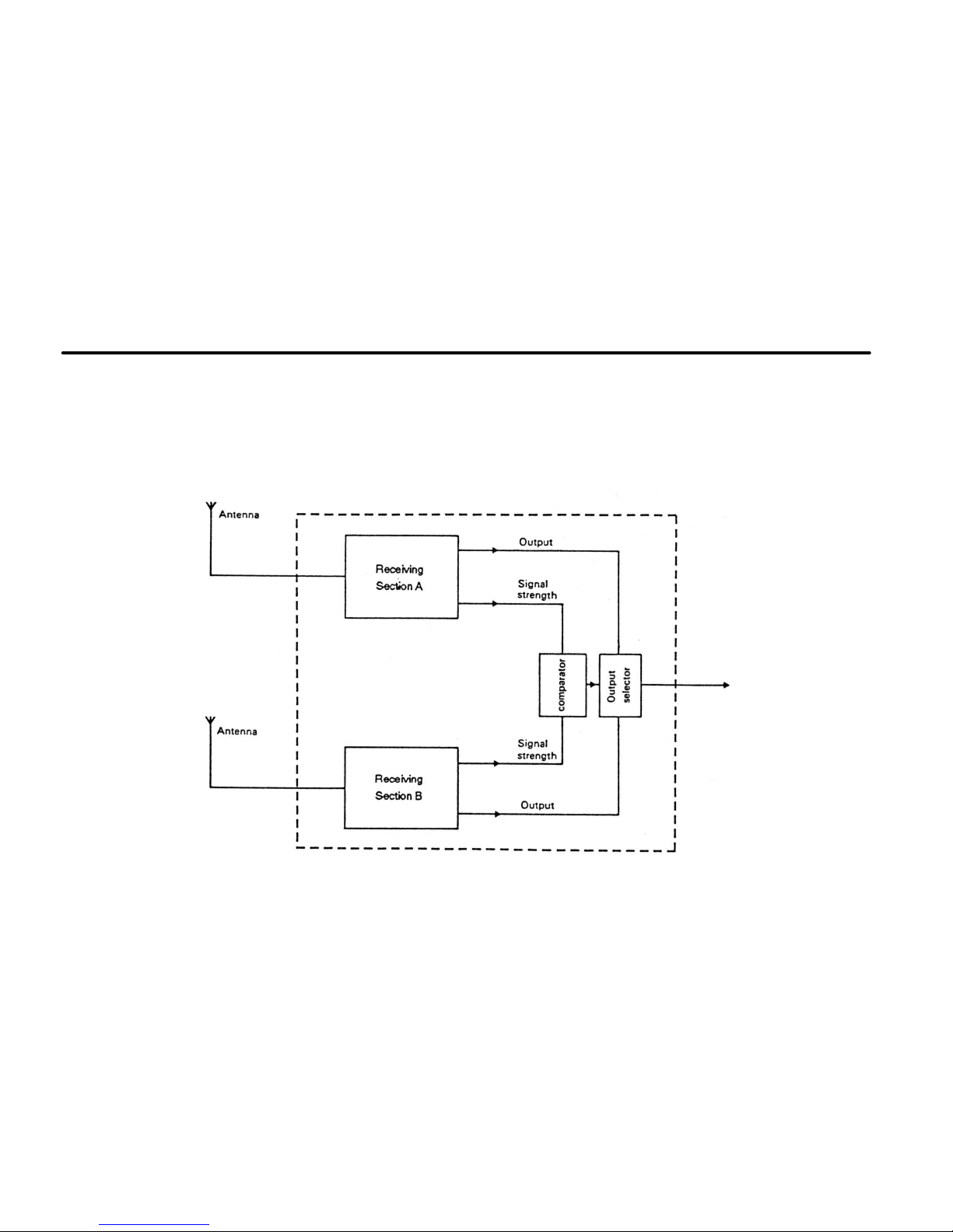
The diagram illustrates how a 2 way diversity system fills in almost all of the dips in received signal
strength by utilising the stronger signal at all times.
Page 10
Diversity
Each SDR Diversity Receiver comprises two receiving sections and a combining unit. The receivers
operate on the same frequency with their antennas spaced apart, the comparator automatically rejecting
the output from the receiver with the weakest received signal. If signals of similar strength are received
the audio outputs are mixed to improve the signal to noise ratio. This audio mixing gives a 3dB
improvement over conventional switched diversity receivers and results in a greater operating range.
Page 11

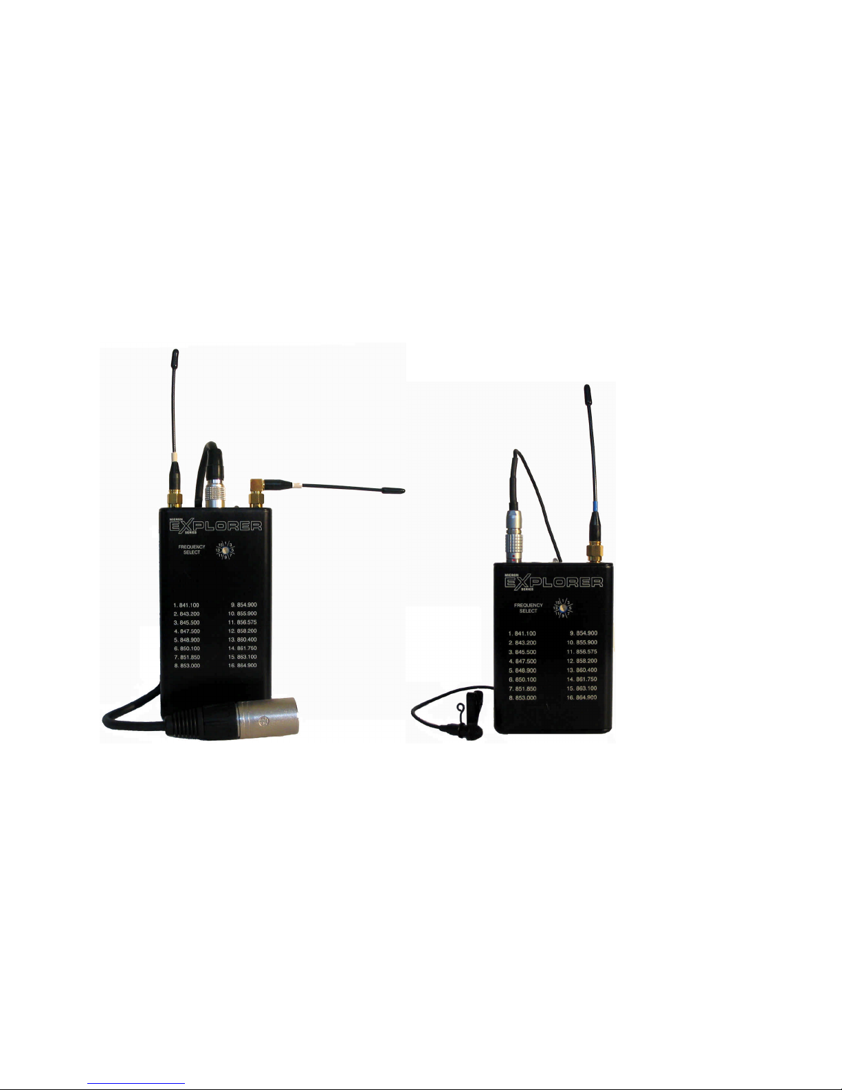
Explorer 100 Transmitters
5
EXPLORER 100 TRANSMITTERS
The Explorer 100’s multi-channel format provides worldwide compliance with regional frequency
allocations and maximum freedom from interference.
Unique Explorer Companding System
An upgraded Explorer Compression/Expansion system ensures best possible signal to noise
performance.
Automatic Gain Control Option
The design of the limiter in the MICRON Explorer 100 transmitter enables it to be used as an automatic
gain control system, without the pumping effect associated with audio AGC systems. It can also be used
as a 'distortionless' limiter, to prevent distortion due to over-modulation.
'Overload-proof' Audio Input Amplifier
The variable -gain microphone amplifier has a gain control range of 40dB. Distortion is less than 0.3%
over the whole of this range.
LED Volume Indicator (AF Peak)
One problem associated with radio microphones is the setting of the modulation level. As with tape
recording, too low a setting results in a poor signal to noise ratio, too high a setting causes distortion. A
common practice is to adjust the audio gain of the transmitter until distortion is heard and then 'back off a
bit'. The MICRON transmitter is fitted with a simple LED volume indicator to allow the modulation level to
be set quickly and accurately, without having to monitor the receiver output. A ‘-10’ indicator is available
only on the TX700B model, which shows modulation metering at 10 dB below limiting level. The
addition of this LED simplifies the setting up procedure making it more accurate.
Page 12

Explorer 100 Transmitter Front Panel
Audio Input Socket
On transmitter models TX716A, TX7256 and TX700B, a 6-pin Lemo connector with gold plated pins is
used for the audio input. TX716 is fitted with a 4-pin Hirose connector for the audio input.
The transmitter offers many audio input options depending on the ‘Transmitter Cable’ selected.
Set Level Control
For easy set-up and repeatable gain settings an eight-position modulation level control is used.
Modulation Level and Battery Status Indicator
The audio input at limiting level is indicated as an AF Peak LED showing modulation status to enable
repeatable levels to be set (with ‘-10’ on TX700B only). Battery Status Indicator operates if the battery
voltage falls below 6.5 Volts.
Antenna Socket
A miniature professional SMA screw socket ensures long-term reliability.
Bass – Cut Switch (TX700B only)
The Bass-Cut switch provides added front-end protection, where it may be used to reduce wind noise and
counteract close microphone effects.
Page 13
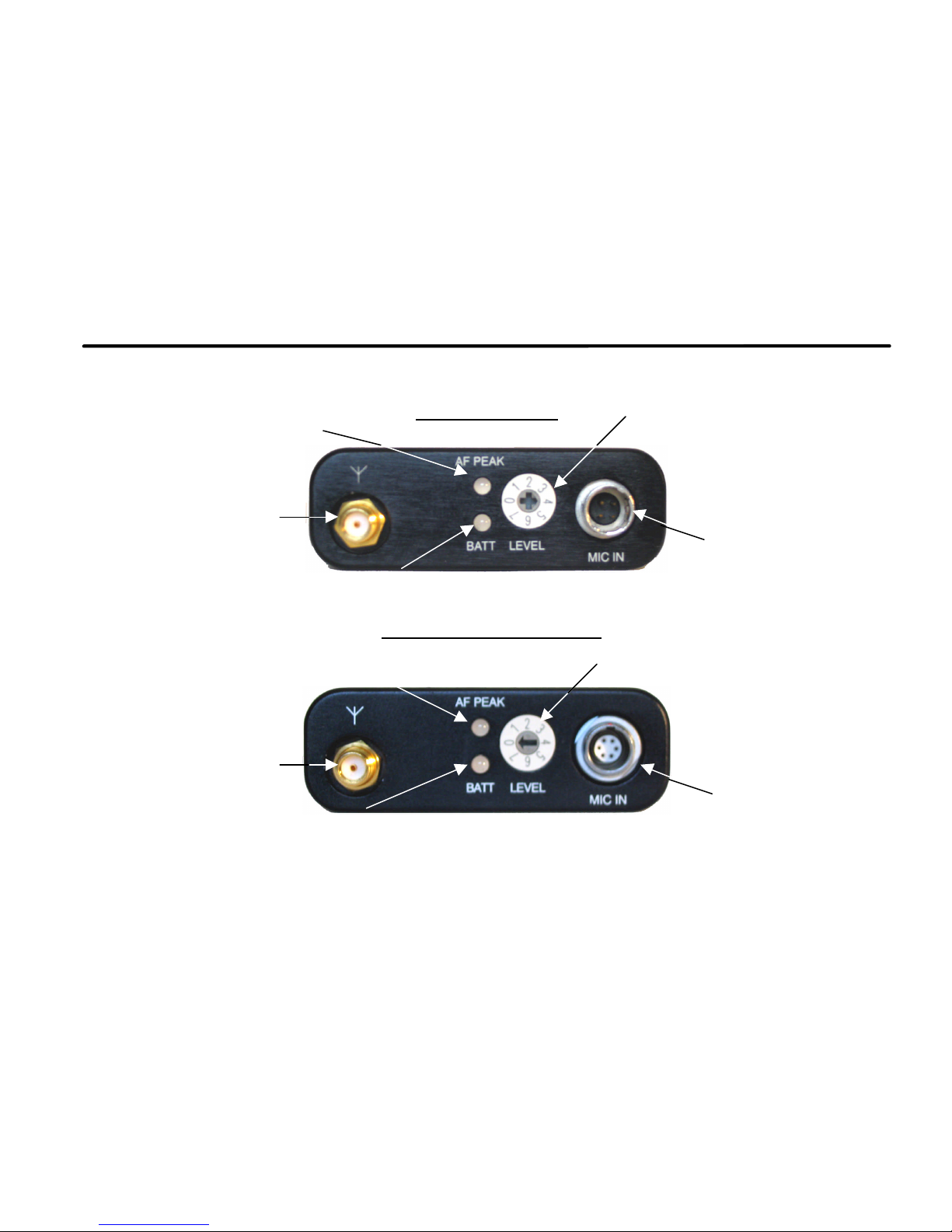
Explorer 100 Transmitter Front Panel
7
TX716 TOP PANEL
TX716A & TX7256 TOP PANEL
Modulation Level
Indicator
Audio Input Socket
4-pin Hirose
Set Level Control
Antenna Socket
Battery Status Indicator
Modulation Level
Indicator
Set Level Control
Audio Input Socket
6-pin Lemo
Antenna Socket
Battery Status Indicator
Page 14

Explorer 100 Transmitter Front Panel
TX700B TOP PANEL
Multiple Input Microphone Socket
The 6-pin Lemo & 4-pin Hirose connectors provide:
1. Direct powering connection for electret microphones (+ve and –ve bias).
2. A high sensitivity input for dynamic microphones.
3. Powering for 12V 'T' powered condenser microphones.
4. Powering for 12V 'Phantom' powered condenser microphones.
5. Powering for 48V 'Phantom' powered condenser microphones with MICRON P48 in-line dc booster.
6. Line input capability.
7. External powering for transmitter.
For each microphone input different cables are available. See: Pages 25 & 26 – Standard Transmitter
Cables.
Modulation Level
Indicator
Antenna Socket
Audio Input Socket
6-pin Lemo
Set Level Control
Battery Status Indicator/ Modulation Level Indicator
Bass Cut Switch
Page 15

Explorer 100 Receivers
9
EXPLORER 100 RECEIVERS
Designed to operate with the new generation of DV camcorders, the Explorer 100 receivers are ultracompact. Useful in situations where receiver size and weight are important, the Explorer 100 receivers
maintain absolute integrity in terms of overall quality, performance and reliability, and is small and light
enough for easy mounting on camcorders.
Offering excellent standard of RF performance, the receivers feature multiple RF stages to give
outstanding sensitivity and selectivity, while the digitally controlled circuitry achieves optimum mobile
operation. The receiver’s unique noise reduction system provides trouble-free operation in low RF signals
and hostile RF environments.
SR116 TOP PANEL
Antenna
Input Socket
Battery Status
Indicator
ON/OFF
Switch
Signal Status
Indicator
4-pin Hirose
Connector
Audio Level
Output Control
Standard Receiver
Page 16

Explorer 100 Receivers Front Panel
SDR116 TOP PANEL
SDR256 TOP PANEL
Audio Level
Output Control
‘A’ Side Signal
Status Indicator
Green
‘B’ Side Signal
Status Indicator
Green
4-pin Hirose
Connector
‘A’ Side Antenna
Input Socket
‘B’ Side Antenna
Input Socket
‘A’ Side Signal
Status Indicator
Tri-colour
‘B’ Side Signal
Status Indicator
Tri-colour
4-pin Hirose
Connector
‘B’ Side Antenna
Input Socket
‘A’ Side Antenna
Input Socket
ON/OFF
Switch
Battery Status
Indicator
Battery Status
Indicator
ON/OFF
Switch
Audio Level
Output Control
Diversity Receivers
Page 17

Explorer 100 Receivers Front Panel
11
SDR550 TOP PANEL
Antenna Input Socket
50 ohm SMA coaxial socket for direct connection of the antenna. Unscrewing its outer shell disconnects
the antenna SMA connector.
Battery Status Indicator (Tri-colour LED)
A tri-colour LED continuously displays the internal/external battery condition.
Transmitter Battery Status (only on SDR550)
A red transmitter battery-warning LED lights up when the supply voltage of the corresponding TX has
fallen to 6.5 Volts (approx.)
4-pin Hirose
Connector
Battery Status
Indicator
‘A’ Side Signal
Status Indicator
Tri-colour
‘B’ Side Signal
Status Indicator
Tri-colour
‘B’ Side Antenna
Input Socket
‘A’ Side Antenna
Input Socket
ON/OFF
Switch
Audio Level
Output Control
TX Battery
Status Indicator
Page 18

Explorer 100 Receivers Front Panel
Signal Status Indicator
SR116: A green LED above the antenna socket displays the received signal strength status.
SDR116: A green LED above each antenna socket continuously display the received signal strength
status.
SDR256, SDR550: A tri-colour LED above each antenna socket continuously display the received signal
strength status.
Audio Level Output Control
SR116: A 3-way slide switch to control the audio output level.
SDR116, SDR256, SDR550: A recessed screwdriver operated volume control.
ON/OFF Switch
Slide switch to turn the receiver ‘ON’ or ‘OFF’. Flush mounted to prevent accidental operation.
Multi-way Connector
A 4-pin Hirose connector provides balanced audio output and dc input connections to the receiver.
Page 19

Frequency Control Panel
13
TX716 SR116
Frequency Switches
16-way BCD
Label
Frequency List
Serial No.
Page 20

Frequency Control Panel
TX716A SDR116
Frequency Switches
16-way BCD
Label
Frequency List
Serial No.
Page 21
Frequency Control Panel
15
Frequency Switches
2 x 16-way BCD
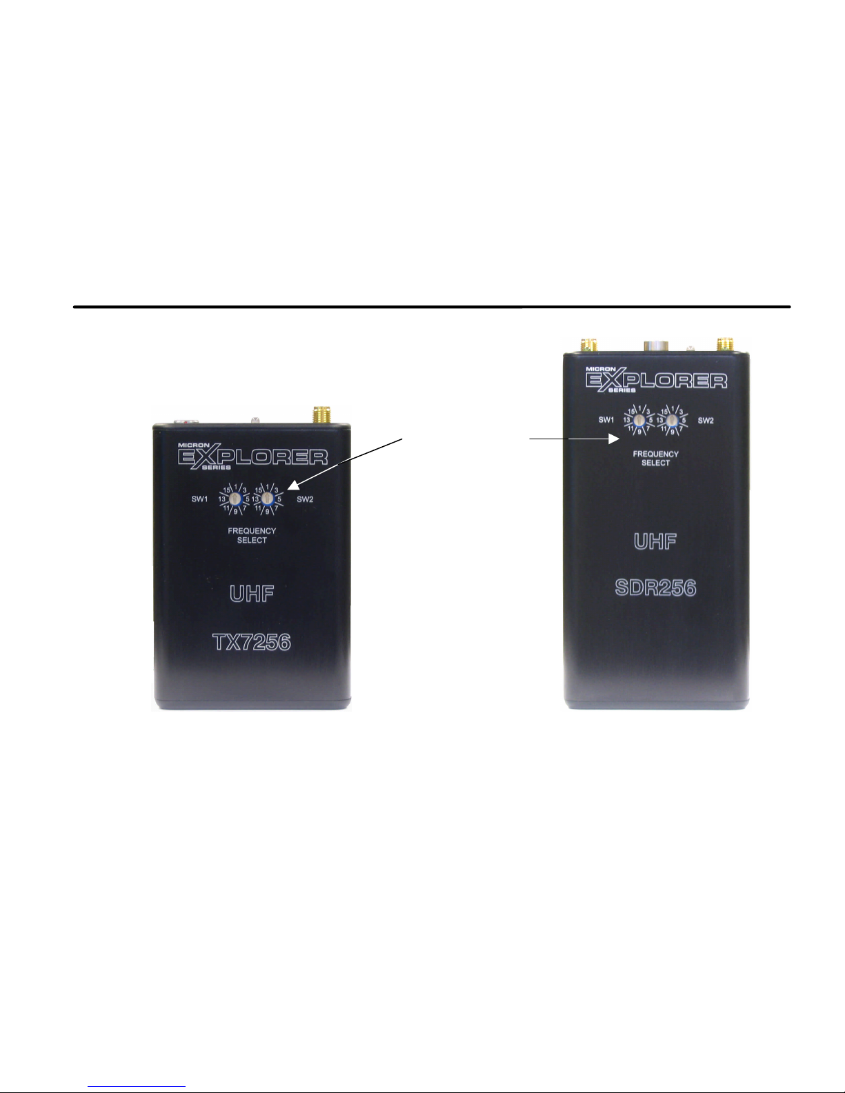
TX7256
Page 22

Frequency Control Panel
Frequency Change Switches
Depending upon the model, the unit is either fitted with a single 16-way BCD (Binary Coded Decimal)
switch or two 16-way (BCD) switches, which give the user a choice of up to 256 different operating
frequencies. The frequency sets are dependant upon the model.
Currently there are 8 models available:
Model Number: Number of Channels: Frequency Range:
SR116, TX716 16 470-870MHz
SDR116, TX716A 16 470-870MHz
SDR256, TX7256 256 470-870MHz
SDR550, TX700B 256 470-870MHz
Serial Number Label
Gives information on:
1) Serial No.
2) Switchable frequencies in MHz (applies to models with 16 channels)
NOTE:
MICRON Explorer 100 pocket transmitters are type tested to meet FCC 47CFR Part 2 & Part 74, from
470-746MHz, and CE and type tested to meet EN 301 489-9 V1.2.1: 2001-EMC and EN 300 422-1
(2000-08) – Radio.
MICRON Explorer 100 receivers are type tested to comply with FCC, EMC and Radio rules from 470-
870MHz.
Page 23

Powering
17
Internal 9V Battery
The internal battery type should be PP3 9V Alkaline or Lithium type IEC 6LR61 (MN1604).
(A) Explorer 100 Receivers
Setting the power switch to ‘ON’ position, will switch the receiver ON.
(B) Explorer 100 Transmitters
Connecting the appropriate standard MICRON audio input lead, or Lavalier Microphone, will switch the TX
ON.
As the transmitter RF driver stage is stabilized, the output power remains virtually constant as the battery
voltage falls. There will be no loss of range or performance as the battery volts fall from 9 to 6 Volts. The
transmitter battery-warning LED lights up when the supply voltage has fallen to 6.5 Volts (approx.)
Opening the battery compartment
The battery compartment is
opened by pressing the button on
the back of the unit. There is a
slot for the 9V battery to fit into.
The battery can easily be
released with the aid of
the thumb.
Page 24

Powering
External Powering
(A) RECEIVERS
External Powering from 7.5 - 16V dc can be supplied by a separate mains unit or from the camera, mixer
or tape recorder batteries, providing they are not +ve earth. Always use recommended MICRON
combinational cables (these cables are fitted with in-line dc-dc regulator and additional filtering).
For powering through the 4-pin Hirose connector, a combination lead is required e.g. AOCPH-HR4
(B) TRANSMITTERS
It is recommended that external power only be applied via a MICRON TLP lead, as this lead includes a 9V
voltage regulator and dc filtering. For powering through the 4-pin Hirose connector or the 6-pin Lemo
connector a combinational lead is required e.g.TLP07CF-6 or TLP07CF-MHR4
It is recommended that the internal batteries be removed when the unit is externally powered. Alkaline and
lithium batteries are the most suitable because of their long life and reliability. They have a long shelf life
and can be relied on to yield their full rated capacity. A conventional 9V transistor radio battery is NOT
recommended.
Battery Life: 6 to 7 hours continuous minimum expected.
Figures are based on a 50mW transmitter @ 25°C
Battery data is approximate, since battery capacity varies with age and ambient temperature, and
transmitter consumption varies with antenna position.
Page 25

Quick Setting Up Procedure
19
Receiver (RX) Setting Up
• Connect provided RX antenna (semi-rigid SMA antenna).
• Fit a PP3 9V Battery, check RX battery status LED.
• Connect Audio output cable and switch on power switch.
• If the battery status LED is AMBER replace RX battery.
• Set the receiver to the required operating frequency.
Interference Check
• Switch off TX - by disconnecting microphone cable.
• Observe signal strength indicator and listen for possible interfering signals from other transmitters
(slight flickering of the RF LED showing RED is acceptable). If there is very strong interference then
change the frequency until you find a clean channel.
• Set the required audio output level (If not sure about output level, this can be set after TX mic gain
has been set)
Transmitter (TX) Setting Up
• Fit a PP3 9V battery
• Connect provided TX antenna (flexible SMA antenna)
• Set your TX frequency same as RX
• Switch on TX (by connecting microphone cable to 6-pin Lemo or 4-pin Hirose socket)
• Check TX battery status LED, if RED replace TX battery with a new one
• Check RX Received Signal Strength Indicator – LED should be GREEN
• Adjust SET LEVEL gain control, while the performer speaks at correct level so that AF Peak LED comes on
all the time, then set gain back by TWO notches - at which AF Peak LED flashes occasionally.
Page 26

Quick Setting Up Procedure
When setting up the TX700B set the gain control so ‘-10’ LED flashes regularly and ‘0’ LED flashes
occasionally.
(for any electret microphones the setting will be Level 4 or 5). The system is now ready to use.
Page 27

How to Get the Best from Explorer
21
The level control, in principle, is a peak limiter. Its function is to prevent distortion due to over modulation.
Because of the singular design, it can be used as an audio AGC system with great improvement over the
'automatic record' facility of most tape recorders. The heart of the system is a voltage controlled variable
gain amplifier, with a control range of 40dB.
The Automatic Level Control (ALC) system can be set so that it operates only in an emergency ('Normal'
mode) or so that it adjusts the gain to suit the user's voice level ('Automatic' mode) or so that it operates
only at extreme levels ('Low modulation' mode).
When used in the 'Automatic' mode, the control system sets the audio gain so that the average speech
level is about 9dB below peak modulation level. This leaves headroom for the short sharp transients,
which occur frequently in speech patterns. Having set the gain, the short transients pass without distortion
and without further need to change the gain.
Connect microphone cable and adjust SET LEVEL control by one of the following methods:
NORMAL
This method suits most situations when there is time for a rehearsal and gives the optimum balance
between dynamic range and signal to noise ratio. Unless an unexpectedly loud sound occurs, the limiter
will not operate.
Adjust SET LEVEL control, while performer speaks at correct level, so the AF PEAK LED flashes occasionally
-and in the case of the TX700B ‘-10’ LED flashes regularly (for any electret microphones the setting will
be Level 4 or 5).
TX is now ready to use.
Page 28

How to Get the Best from Explorer
FULLY AUTOMATIC
This procedure is for News reporting, interviews and other situations where there is no opportunity for
rehearsal with the talent. The objective is to preset the audio gain slightly high and allow the limiter to
control the level.
Speak in an average to quiet voice with the microphone in a realistic position, while adjusting the SET LEVEL
control, so the AF PEAK LED flashes regularly (for any electret microphones the setting will be
Level 6 or 7).
TX is now ready to use.
LOW MODULATION LEVEL
This procedure is for those situations where the dynamic balance of the dialogue must not be altered at
all, such as Theatre Musicals or for stereo productions. In this mode the automatic levelling threshold is
set to be above the highest expected input level.
Adjust SET LEVEL control, while performer speaks at normal level, so the AF PEAK LED NEVER flashes at
all. For Musicals, it may be preferable to adjust the SET LEVEL control on the loudest passage so the AF
PEAK LED does not flash. (For any electret microphones the setting will be Level 0 or 1)
TX is now ready to use.
Page 29

Audio and dc Input/Output Details
23
PCB Mounted 6-Way Lemo Connector. (Front View) Chassis Mounted 4-Way Hirose Connector
Pin
No:
TX716A,TX7256,TX700B TX716 SR116, SDR116, SDR256, SDR550
1
Microphone input 0V 0V
2
-5V out for negative biased
microphones
PWRON
Link
to turn
TX ‘ON’
High Level Output
Signal +
3
BATT+ Volts to power P48 or to
externally power TX with TLP cable
Microphone input
High Level Output
Signal -
Balanced
Switchable
Audio Output
4
Battery -
+9V out for positive
biased microphones
External Supply +ve
5
0V
Link
to turn
TX ‘ON’
N/A N/A
6
+9V out for positive biased
microphones
N/A N/A
}}}
Page 30

Receiver Connector Details
Cable Connectors
All connectors viewed from soldering side. The pin numbers indicate the standard set by MICRON and all
cables in this manual.
• AOCH-HR4: ELECTRONICALLY BALANCED AUDIO OUTPUT CABLE
• AOCPH-HR4: ELECTRONICALLY BALANCED AUDIO OUTPUT CABLE (external powering)
• 2AOCPH-HR4: DOUBLE ELECTRONICALLY BALANCED AUDIO OUTPUT CABLE (external
powering)
Page 31

Standard Transmitter Cables – 6 pin LEMO
25
FOR TX716A, TX7256, TX700B
Dynamic Microphone Cable
• TDN15CF-6 (Dynamic Microphone Cable)
• TDN15CF-6T (Dynamic Microphone Cable, with in-line Transformer)
Condenser AB Powering Cable
• T12 MICRON-6 (Condenser AB Powering Cable)
• P12 MICRON-6 (Low Voltage 12V Phantom Powering Cable)
• P48 MICRON-6 (Phantom Powering 48V)
Line Input With External Powering
• TL20CF-6 (Line Input Cable)
• TLPO7CF-6 (Line Input With External Powering Cable -Y Cable)
• 2TLPO7CF-6 (Double Line Input with External Powering - Y Cable)
Note: All ‘TLP’ cables have in-line dc-dc regulators and dc filtering.
For best results, the following Electret Microphones are recommended:
• KAT66 (pins1+6 link to Red and Pins 4+5 link to Screen and Black)
• Countryman EMW (pins1+6 link to Red and Pins 4+5 link to Screen and Green)
• COS 11 (pins1+6 link to Black and Pins 4+5 link to Screen and White)
• DPA 4060 (pins1+6 link to Inner and Pins 4+5 link to Screen)
• ECM 77 (pins1+6 link to Red and Pins 4+5 link to Screen and White)
• MKE 2 (pins1+6 link to Red and Pins 4+5 link to Blue and Screen)
Any other brand of electret microphone may be used.
Page 32

Standard Transmitter Cables – 4 pin Hirose
FOR TX716
Dynamic Microphone Cable
• DM-MHR4 (Dynamic microphone input adapter cable)
• DM-MHR4T (Dynamic microphone input adapter cable with in-line transformer to give 12dB gain)
Condenser AB Powering Cable
• T12-MHR4 (T-Powering adapter cable)
• P12-MHR4 (12V low voltage condenser microphone powering cable)
• P48 MHR4 (In-line DC to DC booster cable, for 48V phantom power microphones)
Line Input With External Powering
• TL20CF-MHR4 (Line input adapter cable)
• TLP07CF-MHR4 (Line input and external powering adapter cable)
Note: All ‘TLP’ cables have in-line dc-dc regulators and dc filtering.
For best results, the following Electret Microphones are recommended:
• KAT66 (pins 3+4 link to Red and Pins 1+2 link to Screen and Black)
• Countryman EMW (pins 3+4 link to Red and Pins 1+2 link to Screen and Green)
• COS 11 (pins 3+4 link to Black and Pins 1+2 link to Screen and White)
• DPA 4060 (pins3+4 link to Inner and Pins 1+2 link to Screen)
• ECM 77 (pins 3+4 link to Red and Pins 1+2 link to Screen and White)
• MKE 2 (pins 3+4 link to Red and Pins 1+2 link to Blue and Screen)
Any other brand of electret microphone may be used.
Page 33

Technical Specification
27
TX716 SR116 TX716A SDR116
RF TRANSMISSION
SYSYTEM
Carrier Range (to order)
470 to 870MHz 470 to 870MHz 470 to 870MHz 470 to 870MHz
Channels
16 16 16 16
Switching Bandwidth
24MHz 24MHz 24MHz 24MHz
Modulation System
F3EGN F3EGN F3EGN F3EGN
Reference Deviation
40kHz 40kHz 40kHz 40kHz
RF Output Power (ERP)
50mW - 50mW -
Muting level
-
1µV nominal
-
1µV nominal
AUDIO
System Signal to Noise
Ratio
>105 dB >105 dB >105 dB >105 dB
Page 34

Technical Specification
TX716 SR116 TX716A SDR116
System Frequency
Response
80Hz-20kHz 80Hz-20kHz 80Hz-20kHz 80Hz-20kHz
System Distortion @
Limiting threshold
<0.3% THD <0.3% THD <0.3% THD <0.3% THD
Level Control
Manual pre-set,
40dB in 8 steps
3-position switch
Manual pre-set,
40dB in 8 steps
Screwdriver
operated
Volume POT
Hi: 0dBV ± 2dB
Mid:-15dBV± 2dB
Low:-40dBV± 2dB
Balanced variable
output, -42dBV to
0dBV ± 2dB
LED Indicators
Peak AF Level
Indicates AGC
Threshold
Signal Strength:
Green >1µV
No light: Muted
Peak AF Level
Indicates AGC
Threshold
Signal Strength:
(A side & B side)
Green >1µV
No signal: Muted
Page 35

Technical Specification
TX716 SR116 TX716A SDR116
Frequency Control
Screwdriver
pre-set
Screwdriver
pre-set
Screwdriver
pre-set
Screwdriver
pre-set
Battery Type
IEC 6LR61
(MN1604) PP3
size
IEC 6LR61
(MN1604) PP3
size
IEC 6LR61
(MN1604) PP3
size
IEC 6LR61
(MN1604) PP3
size
9V (alkaline) 9V (alkaline) 9V (alkaline) 9V (alkaline)
Current Consumption
65mA +/-10% 55mA +/-10% 65mA +/-10% 80mA +/-10%
Battery Life
>6 hours with
alkaline battery
>6 hours with
alkaline battery
>6 hours with
alkaline battery
>5 hours with
alkaline battery
External Power
7.5 to 16V dc
(with ‘TP’
cables)
7.5 to 16V dc
(with ‘AOCPH-
HR4'’ cables)
7.5 to 16V dc
(with ‘TP’ cables)
7.5 to 16V dc
(with ‘AOCPH-
HR4'’ cables)
Page 36

Technical Specification
TX716 SR116 TX716A SDR116
Battery
Condition
LED
Lights at <6.5V
Green: >7.0V
Amber: >6.5V
Red: <6.5V
No light: Battery
Flat
Lights at <6.5V
Green: >7.0V
Amber: >6.5V
Red: <6.5V
No light: Battery
Flat
Dimensions
Width 63mm Width 63mm Width 63mm Width 63mm
Depth 22mm Depth 22mm Depth 22mm Depth 22mm
Height 91mm Height 91mm Height 91mm Height 120mm
Weight 150 grams
with battery
Weight 150 grams
with battery
Weight 150 grams
with battery
Weight 200 grams
with battery
Accessories
Supplied
Antenna, Belt clip,
Instruction Manual
Antenna, Belt clip,
Instruction Manual
Antenna, Belt clip,
Instruction Manual
2 Antennas,
Instruction Manual
Page 37

Technical Specification
TX7256 SDR256 TX700B SDR550
RF TRANSMISSION
SYSYTEM
Carrier Range (to order)
470 to 870MHz 470 to 870MHz 470 to 870MHz 470 to 870MHz
Channels
256 256 256 256
Switching Bandwidth
32MHz 32MHz 32MHz 32MHz
Modulation System
F3EGN F3EGN F3EGN F3EGN
Reference Deviation
40kHz 40kHz 40kHz 40kHz
RF Output Power (ERP)
50mW - 50mW -
Muting level
-
1µV nominal
-
1µV nominal
AUDIO
System Signal to Noise
Ratio
>105 dB >105 dB >105 dB >105 dB
Page 38

Technical Specification
TX7256 SDR256 TX700B SDR550
System Frequency
Response
80Hz-20kHz 80Hz-20kHz 80Hz-20kHz 80Hz-20kHz
System Distortion @
Limiting threshold
<0.3% THD <0.3% THD <0.3% THD <0.3% THD
Level Control
Manual pre-set,
40dB in 8 steps
Screwdriver
operated
Volume POT
Manual pre-set,
40dB in 8 steps
Screwdriver
operated
Volume POT
Balanced variable
output, -42dBV to
0dBV ± 2dB
Balanced variable
output, -42dBV to
0dBV ± 2dB
LED Indicators
Peak AF Level
Indicates AGC
Threshold
Signal Strength:
(A side & B side)
Green: >25µV
Amber: >5µV
Red: <1µV
No light: Muted
Peak AF Level
Indicates AGC
Threshold '(-10)
lights at 10dB
below ALC
threshold
Signal Strength:
(A side & B side)
Green: >25µV
Amber: >5µV
Red: <1µV
No light: Muted
TX Low Battery Indicator
- - - RED LED when
TX battery<6.5V
Page 39

Technical Specification
TX7256 SDR256 TX700B SDR550
Frequency Control
Screwdriver
pre-set
Screwdriver
pre-set
Screwdriver pre-
set
Screwdriver
pre-set
Battery Type
IEC 6LR61
(MN1604) PP3
size
IEC 6LR61
(MN1604) PP3
size
IEC 6LR61
(MN1604) PP3
size
IEC 6LR61
(MN1604)
PP3
size
9V (alkaline) 9V (alkaline) 9V (alkaline) 9V (alkaline)
Current Consumption
65mA +/-10% 85mA +/-10% 65mA +/-10% 85mA +/-10%
Battery Life
>6 hours with
alkaline battery
> 5 hours with
alkaline battery
>6 hours with
alkaline battery
> 5 hours with
alkaline battery
External Power
7.5 to 16V dc
(with ‘TP’
cables)
7.5 to 16V dc
(with ‘AOCPH-
HR4'’ cables)
7.5 to 16V dc
(with ‘TP’ cables)
7.5 to 16V dc
(with ‘AOCPH-
HR4'’ cables)
Page 40

Technical Specification
TX7256 SDR256 TX700B SDR550
Battery
Condition
LED
Lights at <6.5V
Green: >7.0V
Amber: >6.5V
Red: <6.5V
No light: Battery
Flat
Lights at <6.5V
Green: >7.0V
Amber: >6.5V
Red: <6.5V
No light: Battery
Flat
Dimensions
Width 63mm Width 63mm Width 63mm Width 63mm
Depth 22mm Depth 22mm Depth 22mm Depth 22mm
Height 91mm Height 120mm Height 91mm Height 120mm
Weight 150 grams
with battery
Weight 200 grams
with battery
Weight 150 grams
with battery
Weight 200 grams
with battery
Accessories
Supplied
Antenna, Belt clip,
Instruction Manual
2 Antennas,
Instruction Manual
Antenna, Belt clip,
Instruction Manual
2 Antennas,
Instruction Manual
Page 41

AUDIO ENGINEERING LIMITED, MICRON HOUSE, 3 NEW ROAD, LONDON N8 8TA
Telephone: +44 (0)20 8341 3500 Fax: +44 (0)20 8341 5100
E-mail: sales@micronwireless.co.uk www.micronwireless.co.uk
Page 42

 Loading...