

Micron MTFDHAL1T6TCU, MTFDHAL1T9TCT, MTFDHAL3T2TCU, MTFDHAL3T8TCT, MTFDHAL6T4TCU User Manual
...
Micron 9200 NVMe SSDs
9200 NVMe SSDs
MTFDHAL1T6TCU, MTFDHAL1T9TCT, MTFDHAL3T2TCU,
MTFDHAL3T8TCT, MTFDHAL6T4TCU, MTFDHAL7T6TCT,
MTFDHAL8TATCW, MTFDHAL11TATCW
Features
Features
• Micron® 3D NAND Flash
• PCIe® Gen3: U.2 ×4
•
NVMe™ 1.2
• Capacity
– 9200 ECO: 11.0TB, 8.0TB
– 9200 PRO: 1.92TB, 3.84TB, 7.68TB
– 9200 MAX: 1.6TB, 3.2TB, 6.4TB
• Endurance (total bytes written)
– 1.6TB: Up to 8.8PB
– 1.92TB: Up to 3.5PB
– 3.2TB: Up to 17.5PB
– 3.84TB: Up to 7.0PB
– 6.4TB: Up to 35.1PB
– 7.68TB: Up to 14.0PB
– 8.0TB: Up to 11.7PB
– 11.0TB: Up to 16.1PB
• 512 and 4096 byte sector sizes
• Power: <5W idle, 25W power limited, or unlimited
• Surprise insertion/surprise removal (SISR) and
hot-plug capable
• Power-backed cache
• Steady state performance
form factor)
– Sequential 128KB read: 2.85–3.15 GB/s
– Sequential 128KB write: 1.9–2.3 GB/s
– Random 4KB read: 700K–770K IOPS
– Random 4KB write: 130K–280K IOPS
• Latency to media performance, typical (QD = 1)
– READ: 92–150µs3, WRITE: 21µs
• Reliability
– MTTF: 2 million hours
– Field-upgradable firmware
– UBER: <1 sector per 1017 bits read
• SMBus for drive management
• End-to-end data path protection
• SMART command set support
• Cryptographic erase
• FlexPro (flexible over provisioning)
1
1
1, 2
(varies by capacity and
4
5
• Temperature
6
– 0°C to 80°C SMART temperature
– 0°C to 35°C ambient for U.2
– Temperature protection
• Mechanical/electrical
– U.2: 69.85 × 15.00 × 100.5mm, 12V (–6%/+8%)
• Shock
– U.2: 1500g @ 0.5ms
• Vibration: 3.1 G
5–800Hz @ 30 min/axis
RMS
Controller Features
• NVMe controller
– Number of queues: 128 SQ/CQ pairs
– Weighted round robin with urgent arbitration
• Interrupt coalescing
• NVMe command set attributes
– Completion queue entry size: 16 bytes
– Submission queue entry size: 64 bytes
• 4KB Atomic operations
Notes:
1. User capacity: 1GB = 1 billion bytes;
1TB = 1 trillion bytes;
1PB = 1 peta bytes.
2. Steady state as defined by SNIA Solid State
Storage Performance Test Specification Enterprise v1.1.
3. READ latency varies by capacity.
4. Based on population statistics that are not
relevant to individual units and a T
60°C.
5. 4K sector size support only.
6. Operating temperature is the drive case
temperature as measured by the SMART
temperature. See air flow recommendations.
CASE
of
CCMTD-731836775-10493
9200_u2_nvme_pcie_ssd.pdf - Rev. E 10/17 EN
Products and specifications discussed herein are subject to change by Micron without notice.
1
Micron Technology, Inc. reserves the right to change products or specifications without notice.
© 2016 Micron Technology, Inc. All rights reserved.
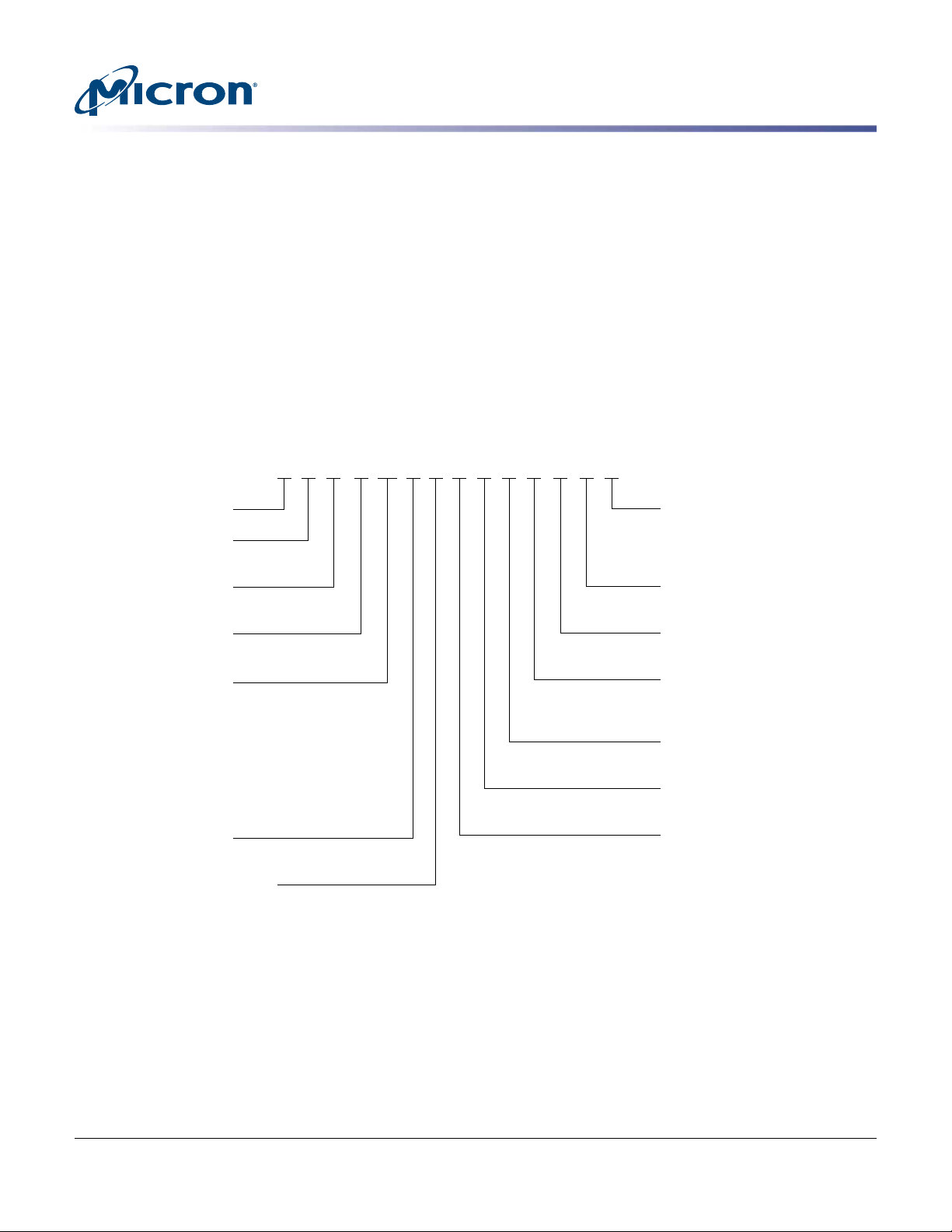
FD H 1T6 T
Micron Technology
Product Family
FD = Flash drive
Drive Interface
H = PCIe Gen3
Drive Form Factor
AL = 2.5-inch, 15mm
Device Capacity
1T6 = 1.6TB
1T9 = 1.92TB
3T2 = 3.2TB
3T8 = 3.84TB
6T4 = 6.4TB
7T6 = 7.68TB
8T0 = 8.0TB
11T0 = 11.0TB
NAND Flash Type
T = TLC
Flash Drive Product Family
CU = 9200 MAX
CT = 9200 PRO
CW = 9200 ECO
Production Status
Blank = Production
ES = Engineering sample
MS = Mechanical sample
Customer Designator
YY = Standard
Additional Features
AB = Standard
Extended Firmware Features
Z = Standard
8 = VPD/SMBUS on by default
Sector Size
1 = 512 Bytes
NAND Component
AR = 384Gb, TLC, x16, 1.8V (3D)
BOM Production
1 = First generation
AL CU 1 Z AB ESAR 1 YY
MT
Micron 9200 NVMe SSDs
Features
Native Drivers
• Microsoft Windows Server® 2016
• Red Hat® Enterprise Linux (RHEL) 6.5+
• CentOS® 6.5+
• SUSE® Linux Enterprise Server 11 SP4, 12+
• Ubuntu® 12.04.03+, 14.04+
Custom Drivers
• Microsoft Windows Server 2012 R2, Hyper-V (recommended)
• RHEL 6.1-6.4
• CentOS 6.1-6.4
• SUSE Linux Enterprise Server 11 SP1-SP3
• VMware® 5.5, 6.0+
Part Numbering Information
The Micron® 9200 SSD is available in different configurations and capacities. Visit www.micron.com for a list of
valid part numbers.
Figure 1: Part Number Chart
Warranty: Contact your Micron sales representative for further information regarding the product, including product warranties.
CCMTD-731836775-10493
9200_u2_nvme_pcie_ssd.pdf - Rev. E 10/17 EN
Micron Technology, Inc. reserves the right to change products or specifications without notice.
2
© 2016 Micron Technology, Inc. All rights reserved.

General Description
The Micron 9200® NVMe SSD Series is Micron's flagship performance product line.
These products utilize a Gen3 PCIe interface, the innovative Non-Volatile Memory Express protocol and Micron's own high-speed NAND to provide high throughput and
IOPS, very low latency, and consistent quality of service. The 9200 product line has Micron's FlexPro™ firmware architecture which allows you to actively tune capacity to optimize drive performance and endurance and is available in high capacities up to 11
TBs. Reliability assurance measures include cyclic redundancy checks (CRC), end-toend data path protection, capacitor-backed power loss protection and Micron's extensive validation, quality and reliability testing. It features thermal monitoring and protection, SMART attributes for status polling and SMBus for out-of-band management.
The Micron 9200 has three endurance classes: the PRO for read-centric use at roughly 1
drive writes per day (DWPD); and the MAX for mixed-use workloads at about 3 DWPD;
and the ECO for less than 1 DWPD. The PRO version comes in 1.92TB, 3.84TB, and
7.68TB capacities, while the MAX is sized at 1.6TB, 3.2TB, 6.4TB, and the ECO in 8.0TB
and 11.0TB.
Logical Block Address Configuration
The number of logical block addresses (LBAs) reported by the device ensures sufficient
storage space for the specified capacity.
Micron 9200 NVMe SSDs
General Description
Table 1: LBA Count in Accordance with IDEMA LBA1-03
Capacity 512-Byte Sector LBA Count 4KB Sector LBA Count
1.6TB 3,125,627,568 390,703,446
1.92TB 3,750,748,848 468,843,606
3.2TB 6,251,233,968 781,404,246
3.84TB 7,501,476,528 937,684,566
6.4TB 12,502,446,768 1,562,805,846
7.68TB 15,002,931,888 1,875,366,486
8.0TB 15,628,053,168 1,953,506,646
11.0TB 21,488,565,168 2,686,070,646
CCMTD-731836775-10493
9200_u2_nvme_pcie_ssd.pdf - Rev. E 10/17 EN
3
Micron Technology, Inc. reserves the right to change products or specifications without notice.
© 2016 Micron Technology, Inc. All rights reserved.
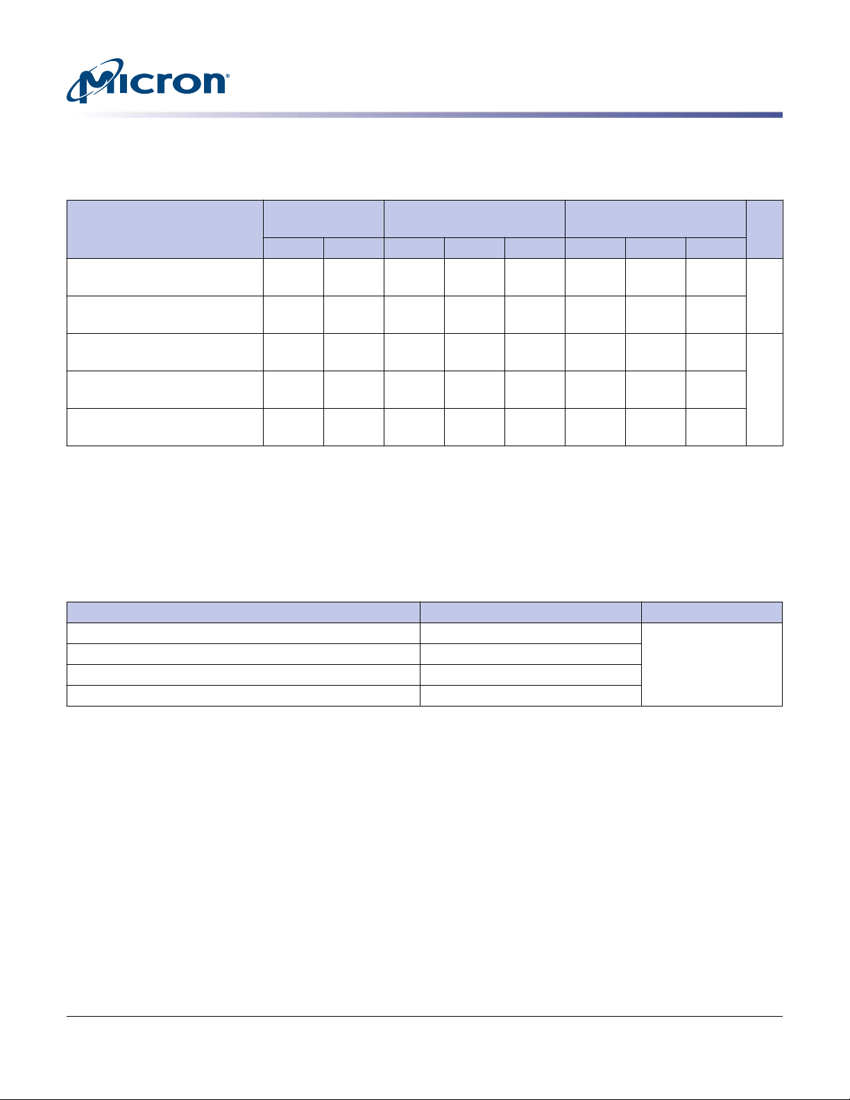
Performance
Table 2: Drive Performance
Micron 9200 NVMe SSDs
Performance
9200 ECO
(TB)
9200 PRO
(TB)
9200 MAX
(TB)
Specification
Sequential read
3.15 3.15 2.85 3.15 3.15 2.85 3.15 3.15 GB/s
(128KB I/O size)
Sequential write
2.3 2.25 1.9 2.3 2.3 1.9 2.3 2.3
(128KB I/O size)
Random read
740K 770K 700K 770K 750K 700K 770K 770K IOPS
(4KB I/O size)
Random write
135K 130K 185K 170K 160K 255K 280K 270K
(4KB I/O size)
Mixed 70/30 read/write
320K 330K 325K 355K 355K 370K 445K 450K
(4KB I/O size)
Notes:
1. Performance specifications shown are with power limiting off. See Electrical Characteristics section for more details.
2. The stated specifications are preliminary.
3. Performance is steady state as defined by SNIA Solid State Storage Performance Test
Specification Enterprise v1.1.
4. Performance may vary up to 10% over life of drive.
Table 3: Latency
Specification Queue Depth = 1 Unit
READ latency (TYP) 1.6TB–3.84TB 92 µs
READ latency (TYP) 6.4TB–8TB 101
READ latency (TYP) 11TB 105
WRITE latency (TYP) all capacities 21
Unit8.0 11.0 1.92 3.84 7.68 1.6 3.2 6.4
Note:
CCMTD-731836775-10493
9200_u2_nvme_pcie_ssd.pdf - Rev. E 10/17 EN
1. Quality of service is measured using random 4KB workloads, QD = 1 at steady state.
4
Micron Technology, Inc. reserves the right to change products or specifications without notice.
© 2016 Micron Technology, Inc. All rights reserved.

Functional Description
Mean Time to Failure
The mean time to failure (MTTF) for the device can be calculated based on the component reliability data using the methods referenced in the Telcordia SR-322 reliability
prediction procedures for electronic equipment and measured during reliability demonstration test.
Table 4: MTTF
Endurance
SSD endurance is dependent on many factors, including: usage conditions applied to
the drive, drive performance and capacity, formatted sector size, error correction codes
(ECCs) in use, internal NAND PROGRAM/ERASE cycles, write amplification factor,
wear-leveling efficiency of the drive, over-provisioning ratio, valid user data on the
drive, drive temperature, NAND process parameters, and data retention time.
Micron 9200 NVMe SSDs
Functional Description
Capacity MTTF (Operating Hours)
All 2.0 million
The device is designed to operate under a wide variety of conditions, while delivering
the maximum performance possible and meeting enterprise market demands.
While actual endurance varies depending on conditions, the drive lifetime can be estimated based on capacity, assumed fixed-use models, ECC, and formatted sector size.
Lifetime estimates for the device are shown in the following tables in total bytes written.
Table 5: Total Bytes Written
Model Capacity (TB) Total Bytes Written (PB)
9200 ECO
9200 PRO
9200 MAX
Note:
1. Values shown are based on system modeling.
8.0 11.7
11.0 16.1
1.92 3.5
3.84 7.0
7.68 14.0
1.6 8.8
3.2 17.5
6.4 35.1
CCMTD-731836775-10493
9200_u2_nvme_pcie_ssd.pdf - Rev. E 10/17 EN
5
Micron Technology, Inc. reserves the right to change products or specifications without notice.
© 2016 Micron Technology, Inc. All rights reserved.

Data Retention
Wear Leveling
Micron 9200 NVMe SSDs
Functional Description
Data retention refers to the capability of the SSD media (that is, NAND flash) to retain
programmed data. The three primary factors that affect data retention are:
• Power-on/power-off state: Data retention generally improves when the SSD is in use
(that is, not shelved in a power-off state).
• Temperature: Data retention decreases as the temperature increases.
• Number of PROGRAM/ERASE cycles on the media: When the SSD ships from the factory, it is typically able to retain user data for up to 5 years in a powered-off state.
Data retention is guaranteed for three months at 40ºC (MAX), which assumes worstcase power and media wear (the SSD remains in a powered-off state and has reached
end of life).
The device uses sophisticated wear-leveling algorithms to maximize endurance by distributing PROGRAM/ERASE cycles uniformly across all blocks in the array. Both static
and dynamic wear leveling are utilized to optimize the drive’s lifespan.
Both types of wear leveling aim to distribute “hot” data away from blocks that have experienced relatively heavy wear. Static wear leveling accomplishes this by moving data
that has not been modified for an extended period of time out of blocks that have seen
few PROGRAM/ERASE cycles and into more heavily worn blocks. This frees up fresher
blocks for new data while reducing expected wear on tired blocks. Dynamic wear leveling, by contrast, acts on in-flight data to ensure it is preferentially written to the leastworn free blocks rather than those closer to the end of their rated life. These techniques
are used together within the controller to optimally balance the wear profile of the
NAND array.
Firmware Update Capability
The SSD supports firmware updates as defined by the NVMe specification. When a
download operation completes, an ACTIVATE command must be issued.
Power Loss Subsystem and Rebuild
The SSD supports an unexpected power loss with a power-backed write cache. No user
data is lost during an unexpected power loss. When power is subsequently restored, the
SSD returns to a ready state within a maximum of 120 seconds.
Boot
The 9200 is not intended to be a bootable device. Boot functionality is not validated by
Micron, and any use in this manner is done at the user's own risk. Please visit Mi-
cron.com to find other SSD products that are recommended for boot.
SMBus Sideband Management
If the system management bus (SMBus) is configured to be enabled, the SSD uses the
SMBus interface for presenting product data, monitoring drive health, checking drive
status before power-up, and error posting.
CCMTD-731836775-10493
9200_u2_nvme_pcie_ssd.pdf - Rev. E 10/17 EN
6
Micron Technology, Inc. reserves the right to change products or specifications without notice.
© 2016 Micron Technology, Inc. All rights reserved.
Micron 9200 NVMe SSDs
Functional Description
Protocol supported: Enterprise SSD Form Factor interface with its accompanying vital
product data (VPD) definition.
Management data and vital product data may be accessed at fixed addresses with
+3.3V
at this fixed address when the drive is fully powered up.
Table 6: Out of Band Management Details
Out of Band Protocol SMBUS Address
Enterprise SSD Form Factor 0x53 0xA6 Vital product data (VPD)
NVMe Management Interface 1.0 0x6A 0xD4 Subsystem management data (SMD)
prior to powering up the drive completely. This data continues to be available
AUX
Alternate Address
(due to bit shift) Data
Notes:
1. SMBUS addresses will appear at an alternate address in certain tools due the inclusion of
direction bit in the SMBUS spec.
2. Out of band management is disabled by default.
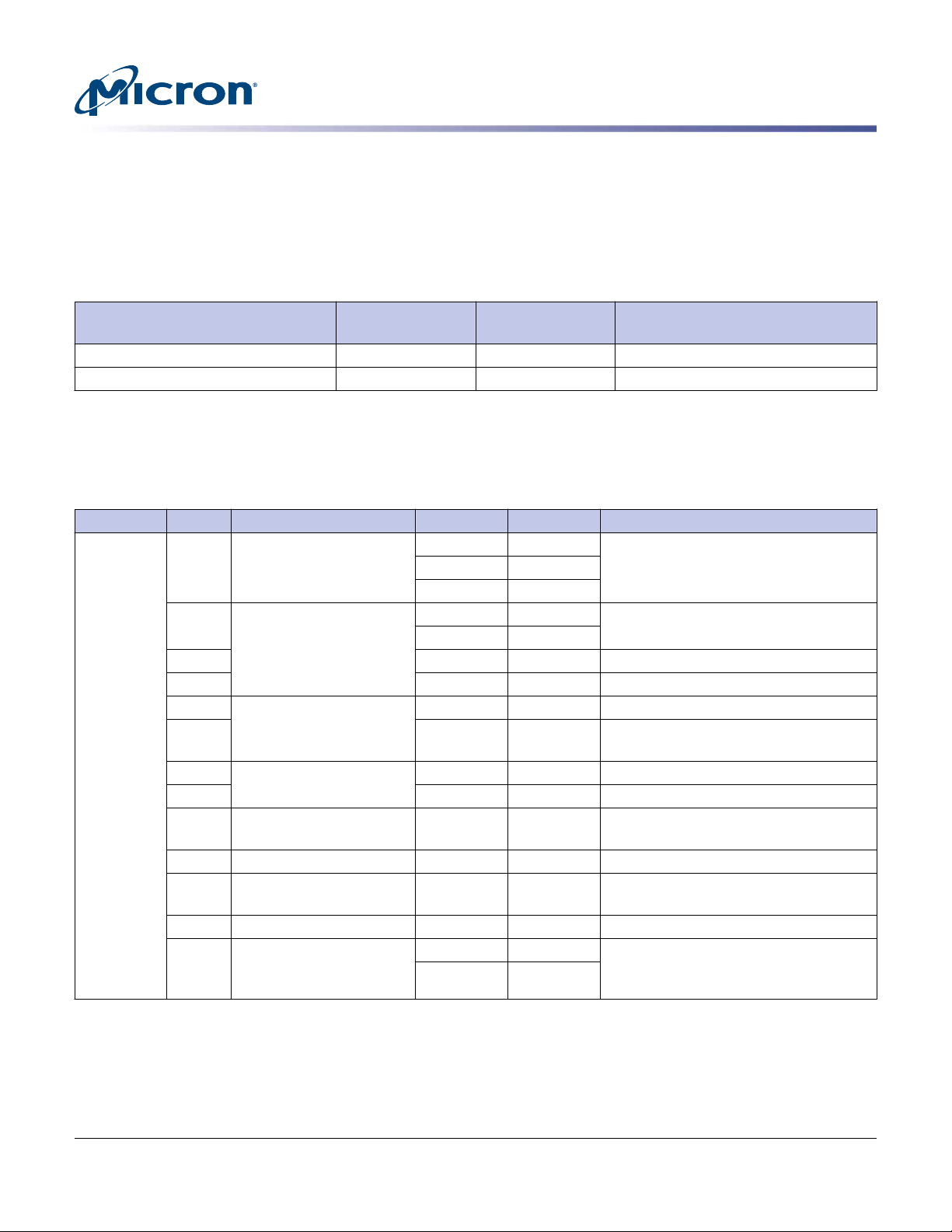
Table 7: Vital Product Data (VPD) Structure
Address #Bytes Function Value Byte Offset Description
0x53
(7bit)
3 Class code 02h 0 Device type and programming interface
08h 1
01h 2
2 ID 44h 3 PCI-SIG vendor ID (0x1344 is assigned to
13h 4
Micron)
20 Varies 5–24 Serial number
40 Varies 25–64 Model number
1 PCIe port0 capabilities 03h 65 Maximum link speed
1 04h/08h 66 Maximum link width (04h if U.2, 08h if
HHHL)
1 PCIe port1 capabilities 00h 67 Maximum link speed
1 00h 68 Maximum link width
1 Initial power requirements 08h 69 12V Power rail initial power requirement
(W)
2 Reserved 0 70–71 –
1 Maximum power require-
ments
24h 72 12V power rail maximum power require-
ment (W)
2 Reserved 0 73–74 –
2 Capability list pointer 4Dh 75 16b address offset pointers to start of ca-
00h 76
pability list, see Capability List Pointer table
CCMTD-731836775-10493
9200_u2_nvme_pcie_ssd.pdf - Rev. E 10/17 EN
7
Micron Technology, Inc. reserves the right to change products or specifications without notice.
© 2016 Micron Technology, Inc. All rights reserved.
 Loading...