

Page 1

Instruction manual
Bromyard Industrial Estate, Bromyard,
Herefordshire, HR7 4HS, UK
Tel: + 44 (0) 1885 482397
Fax: + 44 (0) 1885 483043
E-mail: enquiries@micron.co.uk
URL: http://www.micron.co.uk
Page 2

Page 3

CONTENTS Page
Description ................................................................................................................................ 1
Electrical safety ......................................................................................................................... 2
General safety............................................................................................................................ 3
Operator protection ................................................................................................................... 4
Preparing for spraying ............................................................................................................... 5
Mixing, filling and calibration ................................................................................................... 6
Before spraying ....................................................................................................................... 10
To start spraying ...................................................................................................................... 11
To stop spraying - at the end of each spray pass ..................................................................... 11
To stop spraying - at the end of the spraying operation ........................................................... 11
After spraying.......................................................................................................................... 12
Troubleshooting ...................................................................................................................... 13
Diagram ................................................................................................................................... 14
Parts list ................................................................................................................................... 15
Storage .................................................................................................................................... 16
To clean atomiser assembly .................................................................................................... 16
To clean feed nozzle ................................................................................................................ 16
To service motor and switch ................................................................................................... 17
Replacement of mains cable .................................................................................................... 17
The battery .............................................................................................................................. 16
DESCRIPTION
The ELECTRAFAN 110/240 is a light, air-assisted, hand-held, spinning disc Controlled Droplet Application (CDA) sprayer. It is powered by a mains electric motor
of either 110 volt or 240 volt. The use of a suitable extension cable enables treatments of up to 80m from a power source. The sprayer is designed for intermittent
use. The sprayer with a full spray bottle weighs 3.25 kg. An electric motor spins the
atomiser disc to produce uniformly small droplets which are carried to the target by
an airstream generated by the fan. Liquid is fed by gravity. The ELECTRAFAN
110/240 is designed primarily for the foliar application of insecticides and fungicides
in glasshouses and polytunnels of both water-based mixtures (e.g. ECs, WPs) at 20 to
40 litres/hectare total spray volume and Ultra-Low Volume (ULV) formulations. It is
also used to apply public health insecticides, for applying vaccines to poultry and for
insect control on livestock and in animal housing. When using the ELECTRAFAN
110/240 in an enclosed/confined space a full face shield and respirator must be worn
(see ‘OPERATOR PROTECTION’).
1
Page 4

ELECTRICAL SAFETY
WARNING - THIS APPLIANCE MUST BE EARTHED.
ONLY USE AT THE VOLTAGE SHOWN ON THE LABEL.
The colours of the mains lead of this machine may not correspond with the coloured
markings identifying the terminals in your plug. Therefore proceed as below:
the earth wire is coloured green and yellow and must be connected to the earth
terminal in the plug marked with the letter E or by the earth symbol or coloured green and yellow.
the neutral wire is coloured blue and must be connected to the neutral terminal
marked with the letter N or coloured black.
the live wire is coloured brown and must be connected to the live terminal marked
with the letter L or coloured red.
the IP rating referred to on the label of this machine applies to the motor enclosure only.
The machine should be fitted with a latching 16 amp mains plug to BS 4343/CEE 16
or equivalent. If this or any other type of unfused plug is used, a 5 amp fuse must be
fitted at the fuse board. In the U.K. a 13 amp mains plug to BS 1363A, fitted with a 3
amp fuse, should only be used where this is suitable, taking into account the working
environment, and where the method of operation will not cause the mains connection
to be put under strain. The use of a residual current circuit breaker, preferably incorporating a supply failure automatic drop out facility, is strongly recommended.
An extension lead of up to 80 metres may be fitted using a suitable waterproof cable
connector. The lead should be of heavy duty 3 core flexible cable and of a conductor
size not less than 1.0 mm² (32/0.2 mm). This is essential to avoid excessive voltage
drop. Use the extension lead fully unreeled to prevent overheating. A faulty cable
must be replaced. Ensure the cable does not make contact with the rotating atomiser
disc.
ALL ELECTRICAL CONNECTIONS MUST BE PROPERLY MADE. IF IN
DOUBT CONSULT A QUALIFIED ELECTRICIAN.
2
Page 5

GENERAL SAFETY
Using agrochemicals is a hazardous process, particularly in enclosed areas.
Operators should comply with all relevant legislation and/or regulations governing
the use of agrochemicals and must use appropriate personal protective equipment
(see ‘OPERATOR PROTECTION’). Never use the ELECTRAFAN 110/240 in
potentially explosive atmospheres or spray flammable liquid through it.
The ELECTRAFAN 110/240 can be used with most conventional insecticides and
fungicides, as well as specific ULV formulations (only available in some countries)
which reduce risks in mixing and filling.
Always read the product label carefully to
discover:-
approved applications
maximum dose rates
maximum number of treatments
operator protection required
necessary environmental protection
measures
N.B. ‘Dose rate’ refers to the amount of chemical product applied per hectare.
Never eat, drink, or smoke when working with agrochemicals. After using
agrochemicals or handling equipment wash your hands thoroughly. Keep people
(especially children) and animals out of areas being sprayed.
Always store agrochemicals safely to protect people and animals, and to safeguard
the environment (take special care to avoid water pollution). See spraying sections
for guidelines on safe use of the ELECTRAFAN 110/240 in operation.
3
Page 6

OPERATOR PROTECTION
Always wear the protective clothing items listed on the product label for mixing and
filling. The minimum protective clothing required for spraying with the ELECTRAFAN 110/240 is:
face shield
respirator
rubber gloves and boots
long sleeved shirt
long trousers
Note:
a) Acoustic information: the sound pressure level at the operator’s ear is 90 dB
(A). Using the machine in an enclosed/confined space may cause this level to
increase by up to 6 dB(A). The sound power level of the machine is 94 dB
(A).
The wearing of suitable ear defenders is recommended when using this machine.
b) Vibration: the weighted RMS acceleration value at the hands when using this
machine does not exceed 2.5 m/s².
Always disconnect the sprayer from the mains before servicing or following
‘TROUBLESHOOTING’ procedures.
Never touch the edge of the atomiser disc.
Never insert anything through the fan guard with the machine connected to the bat-
tery.
Never wear loose clothing, e.g. scarves and ties, or any item which could be drawn
into the fan.
Check the sprayer cable frequently for cuts, abrasions and damage. A faulty cable
must be replaced.
4
Page 7

PREPARING FOR SPRAYING
Check that the intended mains supply corresponds to the lable on the machine before
fitting a plug to the mains cable (see ‘ELECTRICAL SAFETY’).
Before connecting to the mains supply check by hand that the atomiser assembly and
fan rotate freely by turning the atomiser assembly in an anti-clockwise direction. (Do
not touch the edge of the atomiser disc). If they are not free to rotate do not attempt
to start the sprayer but contact your supplier or Service Department at Micron.
Plug the sprayer into the mains supply and switch on to check smooth running of the
atomiser disc and fan.
The sprayer must only be used at the rated voltage. The machine must be switched
off in the event of power interruption or failure.
N.B. Before spraying for the first time with the ELECTRAFAN 110/240, sprayer
operation must be checked using only water (see ‘BEFORE SPRAYING’).
CAUTION. The Electrafan 110/240 are not designed for continuous running. A thermal cut out is fitted to the motor to prevent the motor from over heating. If the motor
does over heat the sprayer will stop running, let the motor cool down and the thermal
cut out will reset enabling the operator to carry on spraying.
5
Page 8
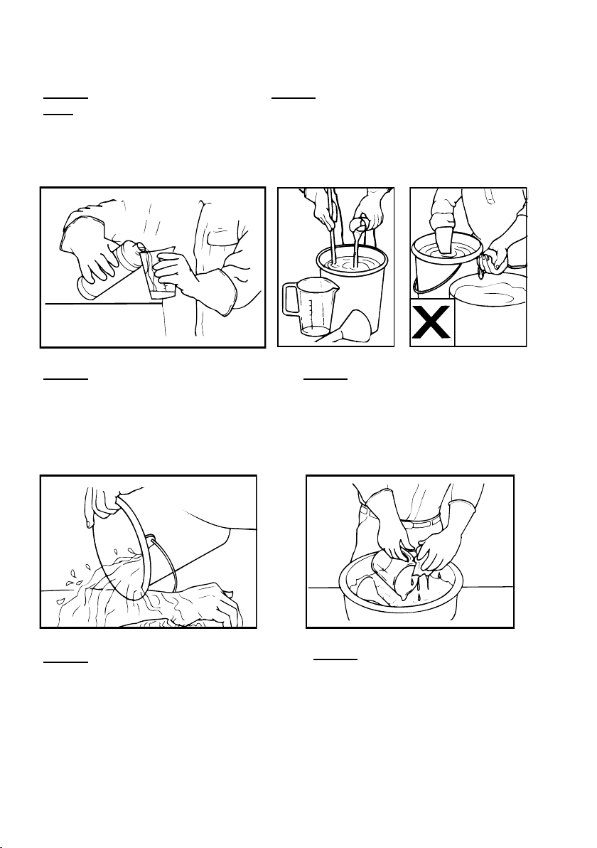
MIXING, FILLING AND CALIBRATION
Mixing and filling is generally the most hazardous process in the spraying operation.
Always follow the label instructions. Always use a funnel when filling the bottle.
Only mix enough spray for the area to be treated if using water-based mixtures to
avoid the need for disposal of unused spray mix.
Always wear gloves when handling
agrochemicals and equipment.
Always wash off any skin
contamination
Always use the correct equipment
when mixing and measuring.
Always clean all equipment after
use.
6
Page 9

ULV FORMULATIONS
ULV formulations will have full instructions for use on the label.
WATER MISCIBLE PRODUCTS
Conventional water miscible insecticides and fungicides are usually applied with the
ELECTRAFAN 110/240 at 20 to 40 litres total spray volume per hectare. Most insecticides can be used at 20 litres/hectare but fungicides may require around 40 litres/
hectare. For example, if the label recommends applying a minimum of 2 litres of insecticide product made up to 100 litres of water per hectare with a conventional
sprayer, use 2 litres of product made up to 20 litres for application with the ELECTRAFAN 110/240, i.e. a spray mix concentration of 10%.
Do not use product concentrations greater than the maximum recommended on the
label (unless specific training or recommendations have been given) if the label:
a) specifically prohibits use of ‘Reduced Volumes’ i.e. increased concentrations;
b) has a statutory requirement for use of personal protective equipment when using
the diluted product at high volumes (N.B. this will appear in the statutory box on
the label); or
c) carries one of the following hazard ratings: ‘very toxic’, ‘toxic’ or ‘corrosive’ or
carries the warning ‘risk of serious damage to the eyes’.
Micron do not generally recommend using spray mixes of more than ten times the
maximum concentration recommended for high volume application. At high concentrations some products can be phytotoxic to crops. Thus, if in doubt, first spray a
small test area. Do not use more than the minimum recommended label dosage rate
i.e. where the label recommendation gives a range of dose rates of, for example, 2 to
3 litres/hectare use no more than 2 litres/hectare. The safest product and lowest dose
rate appropriate for the treatment should be used at all times.
To prepare the spray mix with water miscible products select the dose rate of product
to be applied per hectare (from the product label) and mix in a suitable container.
Examples of mixing spray - for 1 hectare (for 1,000m² i.e. 0.1ha, divide quantities by
10):
a) insecticide: 2 litres
add water: +18 litres
Total volume: 20 litres
i.e. 1 part insecticide : 9 parts water
b) fungicide: 4 litres
add water: +36 litres
Total volume: 40 litres
i.e. 1 part fungicide : 9 parts water
7
Page 10

CALIBRATION
The work rate when using the ELECTRAFAN 110/240 will be dependent on the
particular situation. In glasshouses/polytunnels it will depend on the type of crop
being treated and the row spacing. In crops such as vegetables and flowers it will
generally take around 45 minutes to spray an area of 1,000m² (1/10 of a hectare). It
will often be necessary to spray crops from both sides of the row to ensure adequate
penetration and even coverage e.g. when foliage is dense, when the crop height
exceeds 0.75m or when planting beds are over 2m wide. As the objective is to apply
an even spray cover to all target surfaces it is very important for the operator to direct
the spray carefully at all areas to be treated e.g. if spraying a crop the ELECTRAFAN
110/240 should be moved gently up and down along the height of the crop (with the
machine held to the side and slightly behind the operator’s direction of travel).
Practice spraying - without any spray mix in the bottle - to see what sort of walking
speed is practical.
The table below indicted the relationship between spray volume, flow rate and
walking speed for the ELECTRAFAN 110/240 as per the following formulae:
a) Formula for calculating required flow rate:-
Flow rate = 6 x spray pass interval x total spray volume x walking speed
(ml/min) (m) (l/ha) (m/s)
b) Formula to calculate the volume applied from a known flow rate:-
Measured flow rate (ml/min) x 10 = spray volume (l/ha)
Area sprayed in one minute (m²)
The following table is a guide to liquid flow rates through various feed nozzles:
Feed nozzle Flow rate (ml/min)
(orifice diameter marked
in mm on nozzle)
Water Oil
(7mm²/sec viscosity)
0.9 23 18
1.1 (fitted) 55 40
1.3 63 46
1.4 85 50
1.6 105 56
2.0 N/A 77
N.B. Liquid flow rates should always be measured with the actual spray mix.
Do not use flow rates over 110 ml/min.
8
Page 11

Wear the appropriate protective clothing when checking the flow rate. Choose and fit
the feed nozzle that is likely to be required (see ‘TO CLEAN FEED NOZZLE’ for
fitting instructions). Fill the bottle with the spray mix, attach to the sprayer (avoiding
spillage) and then turn the sprayer over above a suitable container (N.B. do not
switch on the sprayer). Wait until the liquid flow is steady and then allow the liquid
to flow into a measuring container for one minute and measure the volume dispensed.
If the flow rate is very different from that required change the feed nozzle and repeat
the above procedure. If the flow rate is close to that required adjust walking speed.
Example: Required spray volume = 30 l/ha; Spray pass interval = 2 m
Flow rate measured = 85 ml/min
Walking speed (m/s) = Flow rate (ml/min)
6 x spray pass interval (m) x total spray volume (l/ha)
= 85 = 0.24 m/sec
6 x 2 x 30
i.e. 0.24 m/s or 14.4 m in one minute (0.24 x 60)
Mark out a distance of 14.4 m and practice walking it in one minute using the sprayer
as if spraying (see ‘BEFORE SPRAYING’).
9
Page 12

BEFORE SPRAYING
ALWAYS:
wear the recommended protective clothing (see ‘OPERATION PROTECTION’).
plan a spray route before spraying so that the operator walks away from the
treated area.
work towards an exit point.
hold the ELECTRAFAN 110/240 so that it is spraying to the side and slightly behind the operator’s direction of travel.
keep the spray head well away from the body to avoid the risk of direct contamination by the spray.
check the condition of the battery before the spraying operation (if possible the
day before so that there is time to recharge the battery if required).
Resting position
Spraying position
Before spraying for the first time use water only to check the operation of the
sprayer. Put some clean water in the bottle, add a few drops of liquid detergent and
screw it into the bottle holder. When fitting the bottle into the bottle holder tighten
fully and then unscrew by 1/4 of a turn. If this is not done the airbleed may be
blocked causing liquid feed to stop. Check for leaks. Switch on the sprayer with the
bottle below the atomiser disc and then turn the sprayer over so that the bottle is
above the atomiser disc (spray liquid will then flow through the feed nozzle onto the
atomiser disc). This is the spraying position, and spray will immediately be emitted.
Start walking as soon as the sprayer has been turned over. Practice using the sprayer
by walking along a few metres and then stopping spraying (see ‘TO STOP SPRAYING’).
The ELECTRAFAN 110/240 produces small droplets which are barely visible in normal conditions. To check the sprayer output switch on, turn the sprayer into the
spraying position and direct the spray onto a suitable surface such as a pane of glass
or painted surface for a few seconds. A liquid film or mass of small droplets will be
seen.
10
Page 13

TO START SPRAYING
Carrying the ELECTRAFAN 110/240 in the resting position, move to the planned
starting point of the spray operation. With the sprayer still in the resting position,
switch on the motor to check the smooth running of both the atomiser disc and fan.
Never touch the atomiser disc when spinning. Then turn over the sprayer into the
spraying position, pointing it at the target and start walking immediately.
Always hold the ELECTRAFAN 110/240 slightly to the rear so that the operator
walks away from the spray. Always move the machine smoothly to ensure a steady
airstream to carry the spray droplets to the target. When the bottle is empty mark the
position where spraying stopped and restart spraying from this point. Do not walk
through any part of the sprayed area.
TO STOP SPRAYING - AT THE END OF EACH SPRAY PASS
At the end of each spray pass turn the sprayer over into the resting position (with the
bottle underneath the atomiser disc) to stop the liquid flow, then switch off the
sprayer. Move to the start of the next spray pass and start spraying again.
Resting position
Spraying position
TO STOP SPRAYING - AT THE END OF THE SPRAY OPERATION
When spraying is finished if using water based mixtures spray out any remaining
spray mix. ULV formulations can be stored for future use. Make sure that all the
spray liquid is ejected from the atomiser disc when the bottle is empty by keeping the
motor running for a few seconds. Then switch the sprayer off.
11
Page 14

AFTER SPRAYING
1. Dispose of any surplus spray mix according to the product label. Store products safely, locked up and out of the reach of children.
2. It is essential to clean the sprayer and bottle thoroughly after use. If using water-based mixtures a water and detergent mix should be put in the bottle,
swilled around, and then sprayed out onto the treated area. If using ULV formulations use kerosene not water and detergent for cleaning out the sprayer.
The sprayer should be wiped down externally using a cloth. Periodically clean
the atomiser assembly (see ‘TO CLEAN ATOMISER ASSEMBLY’).
3. After working with agrochemicals, or handling spraying equipment, always
thoroughly wash hands and exposed skin. All protective clothing should be
washed and stored separately from other clothing. Contaminated gloves
should be washed inside and out.
12
Page 15

TROUBLESHOOTING
FAULT CHECKING CHART
Problem Procedure
N.B. always disconnect the sprayer from the battery
Motor fails to start
1. Switch Check switch is in ON position.
2. Blown fuse Remove the plug from the mains supply and check fuses.
3. Stiff or seized motor Disconnect from the mains supply. The atomiser assembly should
4. Loose connection in plug or
extension lead
5. Faulty switch, internal wiring or
motor
Motor runs slowly
1. Friction in atomiser assembly or
motor
2. Poor electrical connections Check systematically all external wiring and connections.
3. Worn or defective switch contacts Contact your supplier or Service Department at Micron.
4. Defective motor armature This is often associated with over-heating.
Fails to spray and chemical
dribbling from air bleed hole in
feed line
1. Blocked feed nozze. Remove spray bottle.
Intermittent spraying
1. Blocked air bleed in feed line Remove the spray bottle and clean threads on the bottle and in the
be free to turn in an anti-clockwise direction. Some friction from
motor brushes is normal but if it is difficult to turn by hand contact
your supplier or Service Department at Micron.
Remove the plug from the mains supply and check that all
connections are clean and secure.
Contact your supplier or Service Department at Micron.
Disconnect from the mains supply. The atomiser assembly should
be free to turn in an anti-clockwise direction. Some friction from
motor brushes is normal but if it is difficult to turn by hand contact
your supplier or Service Department at Micron.
Contact your supplier or Service Department at Micron.
Remove and clean feed nozle (see ‘TO CLEAN FEED
neck of the feed line. When fitting the bottle into the bottle holder
tighten fully and then unscrew by 1/4 of a turn. If this is not done
the airbleed may be blocked causing liquid feed to stop. Check the
air bleed hole is clear.
Intermittent spraying and excessive
contamination of fan and fan guard
with repeated blocking of feed
nozzle
1. Blocked atomiser assembly Remove the spray bottle. Remove and clean atomiser assembly
and feed nozzle (see ‘TO CLEAN ATOMISER ASSEMBLY’ and
‘TO CLEAN FEED NOZZLE’).
13
Page 16

ELECTRAFAN 240 PARTS DIAGRAM
63
58
61
27
64
65
66
6
62
56
55
57
59
60
14
Page 17

ELECTRAFAN 110/240 PARTS LIST
Item
Description Part No. Qty. Item
No.
1 Label plate T/4103 1 32 Screw, 4.BA x 1/4” brass roundhead T/5114 3
2 Motor housing with handles T/A4104 1 33 Screw, 2.BA x 1 -1/2” T/5115 1
3 Fan end cover moulding T/4506 1 34 Bolt, 6.BA x 1/2” roundhead T/5124 1
4 Hand grip T/4109 2 35 Screw, D/E 2.BA 1 -5/8” T/5128 3
5 Circular fan guard T/4111 2 36 Screw, D/E 2.BA x 2 - 5/8” T/5129 1
6 Plastic cap 7063 6 37 Nut, 1/4” BSF, nyloc T/5132 1
7 Motor assembly, 110 volt T/4151 ) 1 38 Nut, 4.BA, lock, brass T/5151 5
Motor assembly, 240 volt T/4121 )
8 Switch bracket T/4129 1 40 Washer, 4.BA brass T/5203 2
9 Fan, 20 x 10 (8 x 4) T/4130 1 41 Washer, 4.BA brass, large T/5205 1
10 Label - spray direction T/4145 1 42 Spacer No.6 x 0.270” x 20 G, S/S T/5211 6
11 Machine identication label 8677 1 43 Washer, 2.BA x 3/8” o.d. T/5221 4
12 Outer guard ring assembly T/B4159 1 44 Washer, 6mm T/5225 2
13 Bottle holder and feed line assembly T/A4507 1 45 Washer, DC spring 4.BA T/5234 1
14 Extension tube, bearing & snap ring T/A4509 1 46 Lock washer ext. 2.BA T/5253 6
15 Atomiser support T/4511 1 47 Nut, 6.BA T/5272 1
16 Atomiser back plate with nozzle holder T /A4512 1 48 Rollpin 3/32” x 1/2” T/5304 1
17 Atomiser bearing cover T/4514 1 49 Bead 9.16” plastic T/5309 3
18 Atomiser d isc - front plate T/4515 1 50 Switch T/6043 1
19 Atomiser co llector plate T/4516 1 51 Mains cable 3 cor e 5M T/A6034 -5M 1
20 Atomiser ret ainer nut T/4517 1 52 Switch connector lead T/A6042 1
21 Chemical feed tube (65mm) T/4518- 65mm 1 53 O/on label T/6061 1
22 Feed nozzle - 0.9mm T/4519-0.9mm
Feed nozzle - 1.1mm T/4519-1.1mm 1 55 Label, ear defenders T/6109 1
Feed nozzle - 1.3mm T/4519-1.3mm 1 56 Cable gland T/6110 1
Feed nozzle - 1.4mm T/4519-1.4mm 1 57 Electric connector block T/6113 1
Feed nozzle - 1.6mm T/4519-1.6mm 1 58 Connector 2BA Crimp T/6015 1
Feed nozzle - 2.0mm T/4519-2.0mm 1 59 ‘O’ ring (BS 043) T/6118 1
23 Atomiser dr ive shaft T/4520 1 60 Slinger T/6119 1
24 Motor brush T/4803 1 61 Ho se Clip 5287 1
25 Atomiser asse mbly T/A4827 1 62 Atomiser cover T/2018 2
26 Atomiser e xtension assembly T/A4828 1 63 Wire 1.5mm2 single core green/yellow 7461/60mm 1
27 Bottle with cap, 1 litre 5265A 1 64 Bottle Cap– Black 3216 1
28 Screw, No.6 x 1/4” S/T 4622 2 65 Cor k washer 5353 1
29 Screw, No.4 x 5/8” S/T 4677 2 66 Bott le cap – black 4489 1
30 Screw, No.10 x 1 - 1/2” S/T T/5007 3
31 Screw. 4.BA x 3/8” brass T/5107 1
Description Part No. Qty.
No.
39 Nut,. 2.BA T/5136 5
54 Switch cover T/6062 1
15
Page 18

STORAGE
Before storing the ELECTRAFAN 110/240 for long periods clean the fan guard with
a small brush to remove any deposits and wipe the metal components with an oily rag
to help combat corrosion. Do not use a directed water jet to clean the sprayer.
Store the sprayer in a clean dry place away from direct sunlight. The battery should
be recharged and stored in a cool dry place.
TO CLEAN ATOMISER ASSEMBLY
Always disconnect the sprayer from the mains supply before servicing.
Hold the fan by inserting a pencil or similar between the guard rings near the nameplate. Remove the atomiser spindle nut by turning clockwise when facing the atomiser assembly (left hand thread). If the nut is tight loosen using pliers. Pull off the
atomiser assembly, soak in paraffin, preferably overnight, then drain and dry.
Alternatively, dismantle the atomiser assembly by releasing the 3 clamp screws and
nuts. Clean carefully. When re-assembling be certain to replace the two spacer
washers on each screw before re-fitting the stainless steel rear collector disc.
Check that the bearing cover is in place, then place the atomiser assembly on the
shaft, followed by the atomiser spindle nut (left hand thread). To tighten hold the fan
as above, turn the nut anti-clockwise until finger tight, then rotate the atomiser assembly anti-clockwise. Do not overtighten.
TO CLEAN FEED NOZZLE
Remove the atomiser assembly as above. Remove the bearing cover from the shaft.
To do this it may be necessary to tilt the bearing cover so that there is clearance between the outer diameter of the bearing cover and the feed nozzle.
16
Page 19

Unscrew the feed nozzle using a 6.BA or 5mm AF spanner and clean carefully with a
soft wire, e.g. fuse wire. Clean the feed line with a pipe cleaner. Re-fit the feed nozzle. Before re-fitting the atomiser assembly, screw on a spray bottle filled with either
kerosene (when using ULV formulations) or water and detergent (when using waterbased sprays) and check for free liquid flow. Re-fit the bearing cover and the atomiser assembly, and tighten as previously described.
TO SERVICE MOTOR AND SWITCH
(Only to be carried out by qualified Service Engineers)
Proceed as follows:
1. Remove handle caps and guard retainer screws.
2. Remove outer fan guard and circular guard ring.
3. Remove fan and inner guard.
4. Remove fan drive pin (tight push in), slinger and washer.
5. Remove switch cover (two retainer screws near fan shaft). Note position of large
‘O’ ring and ensure this is re-fitted to the motor housing before re-assembly.
6. Gently pull switch cover clear of the fan shaft and move to one side to expose motor brushes, switch and internal wiring.
N.B. Replacement brushes for the motor are available from Micron. If the armature
or bearings need replacing, a new motor will be required.
When re-assembling:
1. Reverse the above procedure.
2. Make sure the fan drive pin is located in the grooves in the fan hub. This prevents
the fan shaft from rotating when the fan nut is tightened.
REPLACEMENT OF MAINS CABLE (see also ‘ELECTRICAL SAFETY’)
Use 5m of PVC sheathed and insulated 3 core flexible cable with 1mm² (32/0.2mm)
conductors. Strip outer sheath and refit heat protection sleeving to individual leads
using original lead as a pattern.
The diagram below illustrates the correct connections to be made when replacing the
cable:
green and yellow wire to the terminal marked (Earthed)
blue wire to the terminal marked N (Neutral)
brown wire to the terminal marked L (Live)
17
Page 20

DECLARATION OF CONFORMITY
Name of manufacturer or supplier: Micron Sprayers Ltd.
Full postal address: Bromyard Industrial Estate,
BROMYARD, Herefordshire
Country of origin: England
Post code: HR7 4HS
Description of Product: Electric powered, hand-held
agricultural spraying machine.
Name and model number of machine: ELECTRAFAN 110/240
Place of Issue: Bromyard, England
Name of authorised representative: G. S. Povey
Position of authorised Representative: Joint Managing Director
DECLARATION:
I declare that as the authorised Representative, the above information
in relation to the supply/manufacture of this product is in conformity
with the requirements of the Machinery Directive 2006/42/EC, the
73/23/EEC Low Voltage Directive and complies with the relevant
essential health and safety requirements.
Signature of authorised Representative:
18
Page 21

NOTES
19
Page 22

NOTES
20
Page 23

Page 24

 Loading...