

Page 1

Using ProLink® Software
®
with Micro Motion
Transmitters
Instruction Manual
November 1999
Page 2

Page 3

Using ProLink® Software
Copyright ©1992, 1999, Mic ro Motion, Inc. All rights reser ved.
Micro Motion, ELITE, and ProLi nk are regis ter ed t rade m arks, and PHOENIX and
F ASTMASS are service marks of Micro Motion, Inc., Boulder, Colorado. Rosemount,
HART and SMART FAMILY are registered trademarks of Rosemount, Inc., Eden
Prairie, Minnesota. Modbus is a regi st er ed trademark of Modicon , Inc., North
Andover, Massachusetts. Hastelloy is a registered trademark of Haynes International,
Inc., Kokomo Indiana. Inconel is a regi st er ed t rade m a rk of Inco Alloys International,
Inc., Huntington, West Virginia. Teflon and Mylar are registered trademarks of E.I.
DuPont de Nemours Co., Inc., Wilmington, Del aware. Tantalum is a register ed
trademark of Thai Tantalum, Inc., Gurnee, Illinois. Minigrabber is a registered
trademark of ITT Corp., New York, New York.
®
with Micro Motion
Transmitters
Instruction Manual
For technical assistance, phone the Micro Motion Customer
Service Department:
• In the U.S.A., phone 1-800-522-6277, 24 hours
• Outside the U.S.A., phone 303-530-8400, 24 hours
• In Europe, phone +31 (0) 318 549 443
• In Asia, phone 65-770-8155
Page 4

Page 5

Contents
1 Before You Begin
1.1 About the ProLink® program . . . . . . . . . . . . . . . . . . . . 1
Uses of the ProLink
File location . . . . . . . . . . . . . . . . . . . . . . . . . . . . . . . . . 2
1.2 The ProLink
1.3 Customer service. . . . . . . . . . . . . . . . . . . . . . . . . . . . . 3
2 Getting Started
2.1 Overview . . . . . . . . . . . . . . . . . . . . . . . . . . . . . . . . . . . 5
2.2 Communication standards. . . . . . . . . . . . . . . . . . . . . . 6
2.3 Wiring to the transmitter . . . . . . . . . . . . . . . . . . . . . . . 7
2.4 Connecting to the PC and power source. . . . . . . . . . . 12
2.5 Installing the software . . . . . . . . . . . . . . . . . . . . . . . . . 13
2.6 Start-up . . . . . . . . . . . . . . . . . . . . . . . . . . . . . . . . . . . . 18
2.7 Connecting to the transmitter . . . . . . . . . . . . . . . . . . . 18
Windows® hour glass . . . . . . . . . . . . . . . . . . . . . . . . . 21
Switch to another transmitter. . . . . . . . . . . . . . . . . . . . 22
2.8 Communication options. . . . . . . . . . . . . . . . . . . . . . . . 22
Transmitter communication options. . . . . . . . . . . . . . . 22
Software communication options. . . . . . . . . . . . . . . . . 23
2.9 Exit. . . . . . . . . . . . . . . . . . . . . . . . . . . . . . . . . . . . . . . . 25
. . . . . . . . . . . . . . . . . . . . . . . . . . . . . .
®
program. . . . . . . . . . . . . . . . . . . 2
®
kit and system requirements . . . . . . . . . 2
. . . . . . . . . . . . . . . . . . . . . . . . . . . . . . . . .
1
5
3 File Menu: Database
3.1 Overview . . . . . . . . . . . . . . . . . . . . . . . . . . . . . . . . . . . 27
3.2 File selection . . . . . . . . . . . . . . . . . . . . . . . . . . . . . . . . 28
3.3 Database command buttons . . . . . . . . . . . . . . . . . . . . 29
3.4 Offline, save, and upload commands . . . . . . . . . . . . . 30
3.5 Load command . . . . . . . . . . . . . . . . . . . . . . . . . . . . . . 31
3.6 Send command . . . . . . . . . . . . . . . . . . . . . . . . . . . . . . 31
3.7 Remove command . . . . . . . . . . . . . . . . . . . . . . . . . . . 32
3.8 On-screen viewing of transmitter
3.9 Exporting transmitter configuration files . . . . . . . . . . . 32
Using ProLink ® Software with Micro Motion® Transmitters
. . . . . . . . . . . . . . . . . . . . . . . . . . .
Directory list box . . . . . . . . . . . . . . . . . . . . . . . . . . . . . 28
Transmitter configuration files list box . . . . . . . . . . . . . 29
File name text box . . . . . . . . . . . . . . . . . . . . . . . . . . . . 29
Offline and save. . . . . . . . . . . . . . . . . . . . . . . . . . . . . . 30
Upload. . . . . . . . . . . . . . . . . . . . . . . . . . . . . . . . . . . . . 30
configuration files . . . . . . . . . . . . . . . . . . . . . . . . . . 32
27
i
Page 6

Contents
continued
4 File Menu: Print
4.1 Overview . . . . . . . . . . . . . . . . . . . . . . . . . . . . . . . . . . . 33
4.2 Print setup . . . . . . . . . . . . . . . . . . . . . . . . . . . . . . . . . . 33
Select, edit, or create a ticket definition file . . . . . . . . . 34
Destination. . . . . . . . . . . . . . . . . . . . . . . . . . . . . . . . . . 35
Transmitter connections. . . . . . . . . . . . . . . . . . . . . . . . 35
Fields on ticket. . . . . . . . . . . . . . . . . . . . . . . . . . . . . . . 36
Separator and book ends. . . . . . . . . . . . . . . . . . . . . . . 37
4.3 Print . . . . . . . . . . . . . . . . . . . . . . . . . . . . . . . . . . . . . . . 38
4.4 Interval print . . . . . . . . . . . . . . . . . . . . . . . . . . . . . . . . . 39
4.5 Update rate . . . . . . . . . . . . . . . . . . . . . . . . . . . . . . . . . 40
4.6 Print file . . . . . . . . . . . . . . . . . . . . . . . . . . . . . . . . . . . . 41
4.7 Exporting print ticket files to other
software applications. . . . . . . . . . . . . . . . . . . . . . . . 41
5 File Menu: Error and Change Log Files
5.1 Error logging . . . . . . . . . . . . . . . . . . . . . . . . . . . . . . . . 43
Log file name . . . . . . . . . . . . . . . . . . . . . . . . . . . . . . . . 43
Error log options. . . . . . . . . . . . . . . . . . . . . . . . . . . . . . 44
5.2 Change logging . . . . . . . . . . . . . . . . . . . . . . . . . . . . . . 44
Log file name . . . . . . . . . . . . . . . . . . . . . . . . . . . . . . . . 45
Change log options . . . . . . . . . . . . . . . . . . . . . . . . . . . 46
. . . . . . . . . . . . . . . . . . . . . . . . . . . . . . . . .
. . . . . . .
33
43
6 View Menu: Variables
6.1 Overview . . . . . . . . . . . . . . . . . . . . . . . . . . . . . . . . . . . 47
6.2 Process variables window . . . . . . . . . . . . . . . . . . . . . . 47
6.3 Output levels window. . . . . . . . . . . . . . . . . . . . . . . . . . 49
6.4 Copying displayed values to other
software applications. . . . . . . . . . . . . . . . . . . . . . . . 50
7 View Menu: Status
7.1 Overview . . . . . . . . . . . . . . . . . . . . . . . . . . . . . . . . . . . 53
7.2 Fault outputs . . . . . . . . . . . . . . . . . . . . . . . . . . . . . . . . 56
7.3 Critical indicators . . . . . . . . . . . . . . . . . . . . . . . . . . . . . 56
"Not Configured" . . . . . . . . . . . . . . . . . . . . . . . . . . . . . 57
Transmitter failure indicators . . . . . . . . . . . . . . . . . . . . 57
Sensor failure and overrange indicators . . . . . . . . . . . 57
"Analog Input Error" and "Pressure Input Failure" . . . . 62
"Data Loss Possible" . . . . . . . . . . . . . . . . . . . . . . . . . . 62
7.4 Operational indicators . . . . . . . . . . . . . . . . . . . . . . . . . 62
"Calibration Failure" . . . . . . . . . . . . . . . . . . . . . . . . . . . 62
"Slug Flow". . . . . . . . . . . . . . . . . . . . . . . . . . . . . . . . . . 63
Analog and frequency saturated indicators . . . . . . . . . 64
"Raw Flow Overflow" and "Raw Elec.
Zero Overflow". . . . . . . . . . . . . . . . . . . . . . . . . . . . . 66
. . . . . . . . . . . . . . . . . . . . . . . . . .
. . . . . . . . . . . . . . . . . . . . . . . . . . . . .
47
53
ii
Using ProLink® Software with Micro Motion® Transmitters
Page 7

Contents
continued
7.5 Informational indicators . . . . . . . . . . . . . . . . . . . . . . . . 66
"Transmitter Initializing". . . . . . . . . . . . . . . . . . . . . . . . 67
"Calibration In Progress" . . . . . . . . . . . . . . . . . . . . . . . 67
Zero indicators. . . . . . . . . . . . . . . . . . . . . . . . . . . . . . . 67
Analog Fixed indicators . . . . . . . . . . . . . . . . . . . . . . . . 69
"Frequency Output Fixed" . . . . . . . . . . . . . . . . . . . . . . 69
"Burst Mode" . . . . . . . . . . . . . . . . . . . . . . . . . . . . . . . . 69
Event indicators. . . . . . . . . . . . . . . . . . . . . . . . . . . . . . 70
"Error Cleared" . . . . . . . . . . . . . . . . . . . . . . . . . . . . . . 70
"Power Reset" . . . . . . . . . . . . . . . . . . . . . . . . . . . . . . . 70
"Security Breach". . . . . . . . . . . . . . . . . . . . . . . . . . . . . 70
"Display Readback Error" . . . . . . . . . . . . . . . . . . . . . . 70
8 Configure Menu: Characterize
8.1 Overview . . . . . . . . . . . . . . . . . . . . . . . . . . . . . . . . . . . 71
8.2 Flow calibration factor . . . . . . . . . . . . . . . . . . . . . . . . . 73
Sensor and transmitter shipped together . . . . . . . . . . 73
Model RE-01 Remote Electronics Unit replaced
in the field . . . . . . . . . . . . . . . . . . . . . . . . . . . . . . . . 73
Sensor or transmitter replaced in the field. . . . . . . . . . 76
Field flow-calibration . . . . . . . . . . . . . . . . . . . . . . . . . . 76
8.3 Density factors for RFT9739 . . . . . . . . . . . . . . . . . . . . 78
Density characterization for RFT9739. . . . . . . . . . . . . 79
8.4 Density factor for IFT9701/IFT9703 and
RFT9712/RFT9729 . . . . . . . . . . . . . . . . . . . . . . . . . 80
Density characterization for IFT9701/IFT9703 and
RFT9712/RFT9729 . . . . . . . . . . . . . . . . . . . . . . . . . 81
8.5 Slug flow limits. . . . . . . . . . . . . . . . . . . . . . . . . . . . . . . 81
8.6 Temperature factor for RFT9739. . . . . . . . . . . . . . . . . 82
8.7 Pressure compensation with RFT9739 . . . . . . . . . . . . 86
Real-time compensation . . . . . . . . . . . . . . . . . . . . . . . 86
Compensation for stable operating pressures. . . . . . . 87
9 Configure Menu: Transmitter Variables
9.1 Overview . . . . . . . . . . . . . . . . . . . . . . . . . . . . . . . . . . . 91
9.2 Flow units . . . . . . . . . . . . . . . . . . . . . . . . . . . . . . . . . . 93
Special flow units. . . . . . . . . . . . . . . . . . . . . . . . . . . . . 96
Special units of mass for gases. . . . . . . . . . . . . . . . . . 98
9.3 Density units . . . . . . . . . . . . . . . . . . . . . . . . . . . . . . . . 100
API gravity. . . . . . . . . . . . . . . . . . . . . . . . . . . . . . . . . . 100
API standard volume . . . . . . . . . . . . . . . . . . . . . . . . . . 101
9.4 Temperature and pressure units . . . . . . . . . . . . . . . . . 102
9.5 Flow cutoffs . . . . . . . . . . . . . . . . . . . . . . . . . . . . . . . . . 102
9.6 Flow direction . . . . . . . . . . . . . . . . . . . . . . . . . . . . . . . 104
9.7 Internal damping . . . . . . . . . . . . . . . . . . . . . . . . . . . . . 105
. . . . . . . . . . . . . . . .
. . . . . . .
71
91
Using ProLink ® Software with Micro Motion® Transmitters
iii
Page 8

Contents
continued
10Configure Menu: Transmitter Outputs
10.1 Overview . . . . . . . . . . . . . . . . . . . . . . . . . . . . . . . . . 107
RFT9739 outputs . . . . . . . . . . . . . . . . . . . . . . . . . . . 109
IFT9701/IFT9703 outputs . . . . . . . . . . . . . . . . . . . . 109
RFT9712/RFT9729 outputs . . . . . . . . . . . . . . . . . . . 109
10.2 Frequency/pulse output . . . . . . . . . . . . . . . . . . . . . . 109
Frequency/pulse output scaling. . . . . . . . . . . . . . . . 110
Maximum pulse width for RFT9739. . . . . . . . . . . . . 111
K-factor . . . . . . . . . . . . . . . . . . . . . . . . . . . . . . . . . . 112
10.3 Milliamp outputs. . . . . . . . . . . . . . . . . . . . . . . . . . . . 112
Milliamp output variables . . . . . . . . . . . . . . . . . . . . . 112
Range limits . . . . . . . . . . . . . . . . . . . . . . . . . . . . . . . 113
Milliamp output flow cutoffs for RFT9739 and
RFT9712/RFT9729 . . . . . . . . . . . . . . . . . . . . . . . 113
Added damping on RFT9739 outputs . . . . . . . . . . . 114
10.4 Fault indicators for RFT9739 . . . . . . . . . . . . . . . . . . 115
Configuring fault indicators for a Version 2 or
earlier RFT9739. . . . . . . . . . . . . . . . . . . . . . . . . . 116
10.5 Slug duration for RFT9739. . . . . . . . . . . . . . . . . . . . 116
10.6 Control output from RFT9739 . . . . . . . . . . . . . . . . . 117
11Configure Menu: Transmitter Information
11.1 Overview . . . . . . . . . . . . . . . . . . . . . . . . . . . . . . . . . 119
11.2 Transmitter database. . . . . . . . . . . . . . . . . . . . . . . . 121
11.3 Pressure input for RFT9739. . . . . . . . . . . . . . . . . . . 122
11.4 Burst control for RFT9739 and
RFT9712/RFT9729 . . . . . . . . . . . . . . . . . . . . . . . 124
11.5 Sensor database for RFT9739 and
RFT9712/RFT9729 . . . . . . . . . . . . . . . . . . . . . . . 125
. . . . . . .
. . .
107
119
12Configure Menu: Events
12.1 Overview . . . . . . . . . . . . . . . . . . . . . . . . . . . . . . . . . 127
12.2 Configuring event parameters . . . . . . . . . . . . . . . . . 127
12.3 Current levels for milliamp events . . . . . . . . . . . . . . 130
12.4 Reading event states . . . . . . . . . . . . . . . . . . . . . . . . 130
13Configure Menu: Meter Factors
13.1 Overview . . . . . . . . . . . . . . . . . . . . . . . . . . . . . . . . . 131
13.2 Meter factors for mass, volume, and density . . . . . . 131
13.3 Entering meter factors . . . . . . . . . . . . . . . . . . . . . . . 132
iv
Using ProLink® Software with Micro Motion® Transmitters
. . . . . . . . . . . . . . . . . . . . .
. . . . . . . . . . . . .
127
131
Page 9

Contents
continued
14Calibrate Menu
14.1 Overview . . . . . . . . . . . . . . . . . . . . . . . . . . . . . . . . . . 133
14.2 Auto zero. . . . . . . . . . . . . . . . . . . . . . . . . . . . . . . . . . 133
Diagnosing zeroing failure. . . . . . . . . . . . . . . . . . . . . 136
14.3 Programming auto zero for RFT9739 . . . . . . . . . . . . 136
Convergence limit . . . . . . . . . . . . . . . . . . . . . . . . . . . 136
Zero time . . . . . . . . . . . . . . . . . . . . . . . . . . . . . . . . . . 137
14.4 Density calibration . . . . . . . . . . . . . . . . . . . . . . . . . . . 138
Density calibration for RFT9739 . . . . . . . . . . . . . . . . 139
Density calibration for IFT9701/IFT9703. . . . . . . . . . 144
Density calibration for RFT9712/RFT9729 . . . . . . . . 147
14.5 Temperature calibration for RFT9739 . . . . . . . . . . . . 148
14.6 Milliamp output trim . . . . . . . . . . . . . . . . . . . . . . . . . . 151
Preparing for milliamp output trim . . . . . . . . . . . . . . . 151
Performing milliamp output trim. . . . . . . . . . . . . . . . . 152
15Test Menu
15.1 Overview . . . . . . . . . . . . . . . . . . . . . . . . . . . . . . . . . . 155
15.2 Milliamp output testing. . . . . . . . . . . . . . . . . . . . . . . . 156
15.3 Frequency/pulse output testing . . . . . . . . . . . . . . . . . 157
15.4 Test point diagnostics for Version 3 RFT9739 . . . . . 158
. . . . . . . . . . . . . . . . . . . . . . . . . . . . . . . . . . . . .
Performing milliamp output test. . . . . . . . . . . . . . . . . 156
Performing the frequency/pulse output test. . . . . . . . 158
. . . . . . . . . . . . . . . . . . . . . . . . . . . . . . . .
133
155
16Applications Menu
16.1 Overview . . . . . . . . . . . . . . . . . . . . . . . . . . . . . . . . . . 161
16.2 Totalizer control. . . . . . . . . . . . . . . . . . . . . . . . . . . . . 161
16.3 Application builder . . . . . . . . . . . . . . . . . . . . . . . . . . . 163
17Help Menu
17.1 Overview . . . . . . . . . . . . . . . . . . . . . . . . . . . . . . . . . . 165
17.2 Index . . . . . . . . . . . . . . . . . . . . . . . . . . . . . . . . . . . . . 165
17.3 Keyboard. . . . . . . . . . . . . . . . . . . . . . . . . . . . . . . . . . 166
17.4 Using Help. . . . . . . . . . . . . . . . . . . . . . . . . . . . . . . . . 166
17.5 Context-sensitive Help. . . . . . . . . . . . . . . . . . . . . . . . 166
17.6 Getting around in Help. . . . . . . . . . . . . . . . . . . . . . . . 167
17.7 Glossary of terms . . . . . . . . . . . . . . . . . . . . . . . . . . . 168
. . . . . . . . . . . . . . . . . . . . . . . . . . . . . . . . . . . . .
Contents . . . . . . . . . . . . . . . . . . . . . . . . . . . . . . . . . . 167
Search. . . . . . . . . . . . . . . . . . . . . . . . . . . . . . . . . . . . 167
Back. . . . . . . . . . . . . . . . . . . . . . . . . . . . . . . . . . . . . . 167
History . . . . . . . . . . . . . . . . . . . . . . . . . . . . . . . . . . . . 167
Browse. . . . . . . . . . . . . . . . . . . . . . . . . . . . . . . . . . . . 167
Jumping from one Help topic to another . . . . . . . . . . 168
. . . . . . . . . . . . . . . . . . . . . . . . . . . .
161
165
Using ProLink ® Software with Micro Motion® Transmitters
v
Page 10

Contents
continued
Appendixes
Appendix A How to Specify the ProLink® Product . . . . . . . . . . 169
Appendix B Uploading and Downloading Configuration Files
with a Model 268. . . . . . . . . . . . . . . . . . . . . . . . 171
Appendix C Temperature Coefficients for Flow and Density . . 177
Appendix D ASCII Character Set . . . . . . . . . . . . . . . . . . . . . . . 181
Appendix E Transmitter Configuration Worksheets . . . . . . . . . 183
Appendix F Flowmeter Calibration Records . . . . . . . . . . . . . . . 189
Figures
Figure 1-1 ProLink® kit . . . . . . . . . . . . . . . . . . . . . . . . . . . . . . 3
Figure 2-1 PC Interface adaptor . . . . . . . . . . . . . . . . . . . . . . . 5
Figure 2-2 Bell 202 temporary connection to
field-mount transmitters. . . . . . . . . . . . . . . . . . . 8
Figure 2-3 Bell 202 temporary connection to
rack-mount transmitters . . . . . . . . . . . . . . . . . . 9
Figure 2-4 Bell 202 hard-wiring to transmitters or
multidrop networks . . . . . . . . . . . . . . . . . . . . . . 10
Figure 2-5 RS-485 hard-wiring to transmitters or
multidrop networks . . . . . . . . . . . . . . . . . . . . . . 11
Figure 2-6 Installing the PC Interface adaptor . . . . . . . . . . . . 12
Figure 2-7 Configure Communications dialog box . . . . . . . . . 24
Figure 3-1 Transmitter Database dialog box. . . . . . . . . . . . . . 28
Figure 3-2 Change Database Directory dialog box. . . . . . . . . 29
Figure 3-3 File Overwrite dialog box. . . . . . . . . . . . . . . . . . . . 31
Figure 3-4 Typical transmitter configuration file . . . . . . . . . . . 32
Figure 4-1 Print Setup/Ticket Builder dialog box. . . . . . . . . . . 34
Figure 4-2 Ticket File Name dialog box . . . . . . . . . . . . . . . . . 34
Figure 4-3 Add Transmitter Tag dialog box . . . . . . . . . . . . . . 35
Figure 4-4 Edit Field Tag Parameter dialog box . . . . . . . . . . . 36
Figure 4-5 Typical ticket printed using print command . . . . . . 39
Figure 4-6 Typical ticket printed using interval
print command . . . . . . . . . . . . . . . . . . . . . . . . . 39
Figure 4-7 Print - View - Application - Update Rate
dialog box . . . . . . . . . . . . . . . . . . . . . . . . . . . . . 40
Figure 4-8 Select File To Print dialog box. . . . . . . . . . . . . . . . 41
Figure 5-1 Typical error log file. . . . . . . . . . . . . . . . . . . . . . . . 43
Figure 5-2 Error Log dialog box . . . . . . . . . . . . . . . . . . . . . . . 43
Figure 5-3 Typical change log file. . . . . . . . . . . . . . . . . . . . . . 45
Figure 5-4 Change Log dialog box . . . . . . . . . . . . . . . . . . . . . 45
Figure 6-1 Process variables window
for RFT9739 . . . . . . . . . . . . . . . . . . . . . . . . . . . 48
Figure 6-2 Process variables window for
IFT9701/IFT9703 . . . . . . . . . . . . . . . . . . . . . . . 48
Figure 6-3 Process variables window for
RFT9712/RFT9729 . . . . . . . . . . . . . . . . . . . . . . 48
Figure 6-4 Output Levels window for RFT9739 . . . . . . . . . . . 49
Figure 6-5 Output Levels window for IFT9701
or IFT9703. . . . . . . . . . . . . . . . . . . . . . . . . . . . . 50
Figure 6-6 Output Levels window for RFT9712/9729 . . . . . . . 50
Figure 6-7 Copy or Link dialog box. . . . . . . . . . . . . . . . . . . . . 51
vi
Using ProLink® Software with Micro Motion® Transmitters
Page 11

Contents
continued
Figure 7-1 Status window for RFT9739 . . . . . . . . . . . . . . . . . 54
Figure 7-2 Status window for IFT9701/IFT9703. . . . . . . . . . . 55
Figure 7-3 Status window for RFT9712/RFT9729 . . . . . . . . . 55
Figure 7-4 Test Point Diagnostics dialog box. . . . . . . . . . . . . 59
Figure 8-1 Characterize Sensor dialog box
for RFT9739 . . . . . . . . . . . . . . . . . . . . . . . . . . . 72
Figure 8-2 Characterize Sensor dialog box for
IFT9701/IFT9703 or RFT9712/RFT9729 . . . . . 72
Figure 9-1 Configure Transmitter Variables dialog box
for RFT9739 . . . . . . . . . . . . . . . . . . . . . . . . . . . 92
Figure 9-2 Configure Transmitter Variables dialog box
for IFT9701/IFT9703. . . . . . . . . . . . . . . . . . . . . 92
Figure 9-3 Configure Transmitter Variables dialog box for
RFT9712/RFT9729. . . . . . . . . . . . . . . . . . . . . . 92
Figure 9-4 Configure Special Units dialog box
for RFT9739 . . . . . . . . . . . . . . . . . . . . . . . . . . . 97
Figure 9-5 Configure Special Units dialog box for
RFT9712/RFT9729. . . . . . . . . . . . . . . . . . . . . . 97
Figure 9-6 RFT9739 for Gas . . . . . . . . . . . . . . . . . . . . . . . . . 100
Figure 10-1 Configure Outputs dialog box
for RFT9739 . . . . . . . . . . . . . . . . . . . . . . . . . . . 108
Figure 10-2 Configure Outputs dialog box for
IFT9701/IFT9703 . . . . . . . . . . . . . . . . . . . . . . . 108
Figure 10-3 Configure Outputs dialog box for
RFT9712/RFT9729. . . . . . . . . . . . . . . . . . . . . . 108
Figure 11-1 Transmitter Information dialog box
for RFT9739 . . . . . . . . . . . . . . . . . . . . . . . . . . . 120
Figure 11-2 Transmitter Information dialog box for
IFT9701 or IFT9703 . . . . . . . . . . . . . . . . . . . . . 120
Figure 11-3 Transmitter Information dialog box for
RFT9712 or RFT9729. . . . . . . . . . . . . . . . . . . . 120
Figure 12-1 Configure Events dialog box . . . . . . . . . . . . . . . . . 128
Figure 13-1 Configure Meter Factors dialog box . . . . . . . . . . . 132
Figure 14-1 Flow Calibration dialog box for RFT9739 . . . . . . . 135
Figure 14-2 Flow Calibration dialog box for
IFT9701/IFT9703 . . . . . . . . . . . . . . . . . . . . . . . 135
Figure 14-3 Flow Calibration dialog box for
RFT9712/RFT9729. . . . . . . . . . . . . . . . . . . . . . 135
Figure 14-4 Density Point 1 Calibration dialog box
for RFT9739 . . . . . . . . . . . . . . . . . . . . . . . . . . . 140
Figure 14-5 Density Point 2 Calibration dialog box
for RFT9739 . . . . . . . . . . . . . . . . . . . . . . . . . . . 143
Figure 14-6 Density Point 3 Calibration dialog box
for RFT9739 . . . . . . . . . . . . . . . . . . . . . . . . . . . 144
Figure 14-7 Density Point 1 Calibration dialog box for
IFT9701/IFT9703 . . . . . . . . . . . . . . . . . . . . . . . 146
Figure 14-8 Density Point 2 Calibration dialog box
for IFT9701. . . . . . . . . . . . . . . . . . . . . . . . . . . . 146
Figure 14-9 Density Point 1 Calibration dialog box for
RFT9712/RFT9729. . . . . . . . . . . . . . . . . . . . . . 147
Figure 14-10 Density Point 2 Calibration dialog box for
RFT9712/RFT9729. . . . . . . . . . . . . . . . . . . . . . 148
Figure 14-11 Temperature Offset Calibration dialog box . . . . . . 150
Using ProLink ® Software with Micro Motion® Transmitters
vii
Page 12

Contents
continued
Figure 14-12 Temperature Slope Calibration dialog box . . . . . . 150
Figure 14-13 Connecting a reference device to
a transmitter . . . . . . . . . . . . . . . . . . . . . . . . . . . 152
Figure 14-14 Milliamp output trim: setting output to 4 mA . . . . . 153
Figure 14-15 Milliamp output trim: enter measured
low output . . . . . . . . . . . . . . . . . . . . . . . . . . . . . 153
Figure 14-16 Milliamp output trim: enter measured
high output . . . . . . . . . . . . . . . . . . . . . . . . . . . . 154
Figure 15-1 Test Milliamp Outputs dialog box . . . . . . . . . . . . . 157
Figure 15-2 Test Frequency Outputs dialog box. . . . . . . . . . . . 158
Figure 15-3 Test points dialog box . . . . . . . . . . . . . . . . . . . . . . 159
Figure 16-1 Totalizer Control dialog box for RFT9739 and
RFT9712/RFT9729 . . . . . . . . . . . . . . . . . . . . . . 162
Figure 16-2 Totalizer Control dialog box for
IFT9701/IFT9703 . . . . . . . . . . . . . . . . . . . . . . . 162
Figure 17-1 ProLink Help main index . . . . . . . . . . . . . . . . . . . . 165
Figure 17-2 Typical ProLink Help display . . . . . . . . . . . . . . . . . 166
Tables
Table 1-1 ProLink® compatibility . . . . . . . . . . . . . . . . . . . . . . 3
Table 2-1 Wiring diagrams for PC interface
and transmitters . . . . . . . . . . . . . . . . . . . . . . . . 7
Table 2-2 Troubleshooting the "cannot find" message . . . . . 19
Table 2-3 Additional ProLink troubleshooting
information . . . . . . . . . . . . . . . . . . . . . . . . . . . . 22
Table 3-1 Items not saved or restored with the
transmitter database . . . . . . . . . . . . . . . . . . . . . 30
Table 7-1 Status indicators . . . . . . . . . . . . . . . . . . . . . . . . . . 54
Table 7-2 Sensor and transmitter terminal designations. . . . 58
Table 7-3 Troubleshooting excessive drive gain . . . . . . . . . . 59
Table 7-4 Nominal resistance and voltage ranges for
flowmeter circuits . . . . . . . . . . . . . . . . . . . . . . . 60
Table 7-5 Troubleshooting faulty sensor cable . . . . . . . . . . . 60
Table 7-6 Troubleshooting overrange conditions . . . . . . . . . 61
Table 7-7 Troubleshooting operational failures . . . . . . . . . . . 63
Table 7-8 Troubleshooting informational failures. . . . . . . . . . 68
Table 8-1 Temperature coefficients for flow . . . . . . . . . . . . . 74
Table 8-2 Methods for determining RFT9739
density factors. . . . . . . . . . . . . . . . . . . . . . . . . . 80
Table 8-3 Methods for determining IFT9701/IFT9703 or
RFT9712/9729 density factors . . . . . . . . . . . . . 81
Table 8-4 Pressure correction factors . . . . . . . . . . . . . . . . . . 87
viii
Using ProLink® Software with Micro Motion® Transmitters
Page 13

Contents
continued
Table 9-1 Mass flow measurement units for
process variables . . . . . . . . . . . . . . . . . . . . . . 94
Table 9-2 Mass total and mass inventory measurement
units for process variables . . . . . . . . . . . . . . . 94
Table 9-3 Viscosity measurement units for
process variables . . . . . . . . . . . . . . . . . . . . . . 94
Table 9-4 Density measurement units for
process variables . . . . . . . . . . . . . . . . . . . . . . 95
Table 9-5 Temperature measurement units for
process variables . . . . . . . . . . . . . . . . . . . . . . 95
Table 9-6 Volume flow rate measurement units for process
variables (liquids only) . . . . . . . . . . . . . . . . . . 95
Table 9-7 Volume total and volume inventory
measurement units for process variables. . . . 96
Table 9-8 Differential pressure measurement units for
process variables . . . . . . . . . . . . . . . . . . . . . . 96
Table 9-9 Effect of flow direction on outputs. . . . . . . . . . . . 104
Table 9-10 Software versions and dates for
NAMUR compliance . . . . . . . . . . . . . . . . . . . . 105
Table 9-11 Filter coefficients for internal damping on
process variables . . . . . . . . . . . . . . . . . . . . . . 106
Table 10-1 RFT9739 Frequency/pulse variables
and output. . . . . . . . . . . . . . . . . . . . . . . . . . . . 110
Table 10-2 Filter coefficients for added damping on
RFT9739 milliamp outputs . . . . . . . . . . . . . . . 114
Table 11-1 Parameters that increment event registers. . . . . 122
Table 11-2 HART commands for burst mode . . . . . . . . . . . . 125
Table 11-3 Flange types, tube and liner
material options . . . . . . . . . . . . . . . . . . . . . . . 125
Table 12-1 Event setpoint and process
variable comparison . . . . . . . . . . . . . . . . . . . . 128
Table 14-1 Minimum flow rate for third-point
calibration . . . . . . . . . . . . . . . . . . . . . . . . . . . . 139
Table 14-2 Density of air. . . . . . . . . . . . . . . . . . . . . . . . . . . . 141
Table 14-3 Maximum flow rates for Micro Motion
sensors. . . . . . . . . . . . . . . . . . . . . . . . . . . . . . 142
Table 14-4 Density of water . . . . . . . . . . . . . . . . . . . . . . . . . 143
Table 14-5 Milliamp output terminals . . . . . . . . . . . . . . . . . . 151
Table 15-1 Milliamp output terminals . . . . . . . . . . . . . . . . . . 156
Table 15-2 Frequency/pulse output terminals. . . . . . . . . . . . 157
Table 16-1 Totalizer Control for the RFT9739 . . . . . . . . . . . 163
Using ProLink ® Software with Micro Motion® Transmitters
ix
Page 14

x
Using ProLink® Software with Micro Motion® Transmitters
Page 15

1 Before You Begin
1.1 About the ProLink®
program
This manual explains how to use the Micro Motion® ProLink™ software
program under the Microsoft
IBM-compatible personal computers. Before using this instruction
manual, the reader should be familiar with Microsoft Windows.
The ProLink program provides communication between a personal
computer and Micro Motion RFT9739, IFT9701, IFT9703, RFT9712,
and RFT9729 transmitters.
The Micro Motion PC Interface adaptor, included with the ProLink kit,
converts Bell 202 or RS-485 signals to and from the RS-232-C standard
used by personal computers.
The ProLink program presents menus, windows, and dialog boxes
familiar to Microsoft Windows users.
The ProLink program enables off-line editing of transmitter
configurations, and enables transfer of configurations to or from the
ProLink transmitter database or data storage media, or from the
database to a Rosemount Model 268 SMART FAMILY
communicator.
275 HART
The ProLink program cannot be used with a Model
®
Communicator.
®
Windows® graphical environment for
®
hand-held
File Menu: Print File Menu: Log Files View Menu: VariablesBefore You Begin Getting Started File Menu: Database
Using ProLink® Software with Micro Motion® Transmitters
1
Page 16

Before You Begin
The ProLink
®
kit and system requirements
continued
Uses of the ProLink®
program
File location
While using the ProLink program, press F1 at any time for on-line help.
Use the ProLink program to:
• Transfer transmitter configurations to and from the ProLink
transmitter database, the hard drive, diskettes, or the connected
transmitter
• Upload a configuration to a Model 268 hand-held communicator
• Poll for data from devices on a multidrop network
• Set up an error log and change log
• Send data to a printer or an ASCII file
• Configure measurement units and range limits
• Read process variables and output variables
• Configure, read, trim, and test transmitter outputs
• Store messages and information such as sensor serial number and
model, flow tube and liner materials, and flange type
• Calibrate the flowmeter
• Assign events to RFT9739 outputs
• Reset the transmitter internal totalizers
• Troubleshoot the sensor, transmitter, and cable connections
ProLink files are saved to the default ProLink directory on the personal
computer, unless otherwise specified by the user. Such files include:
• Change log files
• Error log files
• Ticket definition files
• Ticket destination files
1.2 The ProLink® kit and
system requirements
If a previous release of the ProLink program is installed:
• The new software may be installed in the same directory as the
earlier version, or in a new directory. The new program files will not
overwrite any configuration or default files that were created
previously.
• The new software will use any configuration and default files that
were created using earlier ProLink versions. However, if the new
software is installed in a directory other than the default ProLink
directory, it might be necessary to locate configuration and default
files manually when using the new program.
The ProLink® kit includes the items illustrated in
replacement parts, see
Appendix A
, page 16 9.
Figure 1-1
. To order
To use the ProLink program, the personal computer must have:
•Intel
®
80386 or higher version microprocessor
• Microsoft Windows version 3.1 or higher
• Hard drive with at least 2.5 MB available for storage
• 4 MB random-access memory (RAM)
• An available 9-pin or 25-pin serial port for RS-232-C communication
ProLink software compatibility with Micro Motion transmitters and
Rosemount hand-held communicators is listed in
Table 1-1
.
2
Using ProLink® Software with Micro Motion® Transmitters
Page 17

continued
Before You Begin
Customer service
Table 1-1. ProLink® compatibility
Transmitter/communicator ProLink® software requirement
RFT9739 Version 3.6 ProLink version 2.4
RFT9739 Version 3, 3.5 ProLink version 2.3
RFT9739 Version 2 ProLink version 2.1
RFT9739 earli er tha n versio n 2 Any ProLink version
IFT9701, IFT9703 ProLink version 2.2 or higher
RFT9712, RFT9729 Any ProLink version*
®
HART
Communicator Mode l 275 Not compatible with ProLink pr ogram
SMART FAM I LY
*RFT9712 and RFT97 29 r equire transmitter software version 5.0 or higher.
®
Interface Model 268 Any Pro Link version
Figure 1-1. ProLink
®
kit
PC Interface
adaptor
1.3 Customer service
AC/DC power
converter
3.5-inch diskette
25-pin to 9-pin converter
Bell 202 cable
For technical assistance with the ProLink software program or any Micro
Motion product, contact the Micro Motion Customer Service
Department:
• In the U.S.A., phone
1-800-522-MASS
(1-800-522-6277), 24 hours
• Outside the U.S.A., phone 303-530-8400, 24 hours
• In Europe, phone +31 (0) 318 549 443
• In Asia, phone (65) 770-8003
File Menu: Print File Menu: Log Files View Menu: VariablesBefore You Begin Getting Started File Menu: Database
Using ProLink® Software with Micro Motion® Transmitters
3
Page 18

4
Using ProLink® Software with Micro Motion® Transmitters
Page 19

2 Getting Started
2.1 Overview
Figure 2-1. PC Interface adaptor
Depending on the transmitter model, communication with the flowmeter
uses the Bell 202 and/or RS-485 communication standards. The PC
Interface adaptor, shown in
signals from the flowmeter to and from the RS-232-C standard used by
personal computers.
Installing the ProLink program requires the following four steps:
1. Choose a communication standard, as described in
2. Connect the PC Interface adaptor to the transmitter, as described in
Section 2.3
3. Install the PC Interface adaptor to the personal computer and a
power supply, as described in
4. Install the ProLink software program, as described in
.
Figure 2-1
Section 2. 4
, converts Bell 202 or RS-485
Section 2.2
.
Section 2.5
.
.
File Menu: Print File Menu: Log Files View Menu: VariablesBefore You Begin Getting Started File Menu: Database
Using ProLink® Software with Micro Motion® Transmitters
5
Page 20

continued
Getting Started
Communication standards
2.2 Communication standards
Switches and jumpers on the transmitter determine the communication
standard used by the transmitter. Micro Motion configures each
transmitter's default communication settings at the factory.
Depending on the transmitter model, transmitters can communicate
using HART and/or Modbus
®
protocol, using the Bell 202 or RS-485
standard. Communication configuration for the ProLink program and
transmitter must be the same.
Factory-default settings
The factory default settings for Version 3 RFT9739 transmitters are:
• HART protocol over the Bell 202 standard at 1200 baud, 1 stop bit,
odd parity
• Modbus protocol over the RS-485 standard at 9600 baud, 1 stop bit,
odd parity
The factory default settings for the IFT9701, IFT9703, RFT9712, and
RFT9729 are: HART protocol over the Bell 202 standard at 1200 baud, 1
stop bit, odd parity.
User configuration
Transmitter models RFT9739, RFT9712, and RFT9729 can be
reconfigured for user-defined communication settings using switches
and jumpers on the transmitter. To establish a user-defined
communication configuration, see the transmitter instruction manual.
®
HART
and Modbus® communication
The primary variable milliamp output on the RFT9739, and the 4-20 mA
output on the IFT9701, IFT9703, RFT9712, and RFT9729 can produce
HART-compatible signals for Bell 202 communication.
Micro Motion transmitters can function as part of a Bell 202 or RS-485
multidrop network.
• The RFT9739 can use the Bell 202 or RS-485 standard under HART
protocol, or the RS-485 standard under Modbus protocol.
• The IFT9701 and IFT9703 can use the Bell 202 standard under
HART protocol only.
• The RFT9712 and RFT9729 can use the Bell 202 or RS-485
standard under HART protocol only.
Up to 15 transmitters can participate with other devices in a Bell 202
multidrop network. Each transmitter must have a unique polling address
of 1 to 15, or a unique tag name.
Up to 32 transmitters can participate in an RS-485 multidrop network.
Each transmitter must have a unique tag name; up to 15 transmitters
may have unique polling addresses from 1 to 15. The IFT9701 and
IFT9703 cannot communicate in an RS-485 network.
6
Using ProLink® Software with Micro Motion® Transmitters
Page 21

continued
Getting Started
Wiring to the transmitter
2.3 Wiring to the transmitter
Wiring connections to RFT9739, IFT9701, IFT9703, RFT9712, and
RFT9729 transmitters are shown on the following pages. The configured
communication standard (Bell 202 or RS-485) determines how the
transmitter and PC Interface adaptor are wired together.
Table 2-1
lists the appropriate wiring diagrams for temporary
connections to transmitters using the Bell 202 standard, and for
hard-wiring to individual transmitters and multidrop networks using the
Bell 202 and RS-485 standards.
Table 2-1. Wiring diagrams for PC interface and transmitters
Communication standard Type of Connection Transmitters Wiring diagram
Bell 202
2
RS-485
1
There are no temporary field connection s on t he IFT9701 or IFT9703.
2
RS-485 not supported by the IFT9701 or IFT9703.
Temporary connection to
field-mount transmitters
Temporary connection to
rack-mount transmitters
Hard-wiring to individual
transmitters or multidrop
networks
Hard-wiring to individual
transmitters or multidrop
networks
RFT9739
1
RFT9712
RFT9739
RFT9729
RFT9739
IFT9701
IFT9703
RFT9712
RFT9729
RFT9739
RFT9712
RFT9729
Figure 2-2
Figure 2-3
Figure 2-4
Figure 2-5
File Menu: Print File Menu: Log Files View Menu: VariablesBefore You Begin Getting Started File Menu: Database
Using ProLink® Software with Micro Motion® Transmitters
7
Page 22

continued
Getting Started
Wiring to the transmitter
Figure 2-2. Bell 202 temporary connection to field-mount transmitters
DCS or PLC
with internal
R2
resisitor
(Note 2)
14 15 16 17 18 19 20 P
21 22 23 24 25 26 27 S
RFT9739
field-mount
Communicator hook-up loops
same as primary mA output
wiring circuit at left
R1
(Note 1)
R3
(Note 3)
R4
(Note 4)
AC
Adaptor
Receive
Transmit
Power
Low Batt
485
A
202 Off 485
202
B
Receive
Transmit
Power
AC
19 18 17 16 15 14
2625242322
Communicator legs
same as primary mA
output wiring circuit
21
at left
R4
(Note 4)
Adaptor
Low Batt
485
A
202 Off 485
202
B
RFT9712
Notes for Figure 2-2
1.
If necessary, add resistance in the loop by installing resistor R1. SMART FAMILY devices require a minimum loop resistance of
250 ohms. Loop resistanc e must not exceed 1000 ohms, regardless of the com mu ni ca tion setup.
CAUTION
Connecting a HART device to the transmitter’s primary analog output could cause transmitter output
error.
If the primary variable analog output is being used for flow control, connecting a PC interface adaptor to the
primary analog output loops or leg s cou ld ca use t he tr ansm itter 4- 20 mA output to change, whic h wo uld a ff e ct flo w
control devices.
Set control devices for manual operation before connecting a PC interface adaptor to the transmitter’s primary
analog output loops or legs.
2.
The DCS or PLC must be configured for an active milliamp signal.
3.
Resistor R3 is required if the D C S or PLC does not have an internal resi st or.
4.
Resistor R4 is required if the illustrated transmitter output wiring is not connected to an input device. Required loop resistance:
minimum 250 ohms, maxi mum 1000 ohms. Wrap ends of resistor aro und prongs of plug before inserting into jack.
8
Using ProLink® Software with Micro Motion® Transmitters
Page 23

continued
Getting Started
Wiring to the transmitter
Figure 2-3. Bell 202 temporary connection to rack-mount transmitters
DCS or PLC
with internal
resisitor
(Note 2)
R2
R3
(Note 3)
R1
(Note 1)
B14
B16
CN2
CN2
RFT9739
rack-mount
R4
(Note 4)
AC
Adaptor
Receive
Transmit
Power
Low Batt
485
A
202 Off 485
202
B
HART jack
same as primary mA output
wiring circuit at left
Z30D30
Connect two Bell 202 cables
Second Bell 202 cable
not included
Receive
Transmit
Power
RFT9729
HART jack same as primary mA output
wiring circuit at left
(Note 4)
R4
AC
Adaptor
Low Batt
485
A
202 Off 485
202
B
File Menu: Print File Menu: Log Files View Menu: VariablesBefore You Begin Getting Started File Menu: Database
Connect two Bell 202 cables
Second Bell 202 cable
not included
Notes for Figure 2-3
1.
If necessary, add resistance in the loop by installing resistor R1. SMART FAMILY devices require a minimum loop resistance of
250 ohms. Loop resistanc e must not exceed 1000 ohms, regardless of the com mu ni ca tion setup.
CAUTION
Connecting a HART device to the transmitter’s HART jack could cause transmitter output error.
If the primary variable analog output is bein g used f o r flo w control, co nnect ing a PC interface adaptor to the HART
jack could cause the transmitter 4-20 mA output to change, which would affect flow control devices.
Set control devices for manual operation before connecting a PC interface adaptor to the transmitter’s HART jack.
2.
The DCS or PLC must be configured for an active milliamp signal.
3.
Resistor R3 is required if the D C S or PLC does not have an internal resi st or.
4.
Resistor R4 is required if the illustrated transmitter output wiring is not connected to an input device. Required loop resistance:
minimum 250 ohms, maxi mum 1000 ohms. Wrap ends of resistor aro und prongs of plug before inserting into jack.
Using ProLink® Software with Micro Motion® Transmitters
9
Page 24

continued
Getting Started
Wiring to the transmitter
Figure 2-4. Bell 202 hard-wiring to transmitters or multidrop networks
DCS or PLC
with internal
resisitor
(Note 2)
R2
R3
(Note 3)
R1
(Note 1)
14 15
16 17 18 19 20 P
212223 24 25 26 27 S
CN2
Z30D30
RFT9739
rack-mount
4–20mA
CN2
B14
B16
19 18 17 16 15 14
RFT9729
26 25 24 23 22 21
AC
Adaptor
202
202 Off 485
Receive
Transmit
Power
Low Batt
485
A
B
RFT9739
field-mount
IFT9701 RFT9712
IFT9703
Notes for Figure 2-4
1.
If necessary, add resistance in the loop by installing resistor R1. SMART FAMILY devices require a minimum loop resistance of
250 ohms. Loop resista nce must not exceed 1000 ohms (6 00 ohms for an IFT9701), regard l ess of the communication set u p.
CAUTION
Connecting a HART device to the transmitter’s primary milliamp output loop could cause transmitter
output error.
If the primary variable analog o utput is being used f or flo w contro l, connec ting a PC int erface adaptor to the output
loop could cause the transmitter 4- 20 mA output to change, which would affect flow control devic es.
Set control devices for manual operation before connecting a PC interface adaptor to the transmitter’s primary
variable milliamp output loop.
2.
The DCS or PLC must be configured for an active milliamp signal.
3.
Resistor R3 is required if the D C S or PLC does not have an internal resi st or.
10
Using ProLink® Software with Micro Motion® Transmitters
Page 25

continued
Getting Started
Wiring to the transmitter
Figure 2-5. RS-485 hard-wiring to transmitters or multidrop networks
DCS or PLC
with internal
resistor
R2
R3
R1
(See Note)
14 15 16 17 18 19 20 P
21 22 23 24 25 26 27 S
CN2
Z30D30
RFT9739
rack-mount
4-20 mA
CN2
B14
B16
RFT9729
19 18 17 16 15 14
26 25 24 23 22 21
AC
Adaptor
Receive
Transmit
Power
Low Batt
485
A
202 Off 485
202
B
Note for Figure 2-5
RFT9739
field-mount
IFT9701
IFT9703
RFT9712
For long-distance communication, or if noise from an external source interferes
with the signal, install 120-ohm, ½-watt resistors across terminals of both end
devices.
File Menu: Print File Menu: Log Files View Menu: VariablesBefore You Begin Getting Started File Menu: Database
Using ProLink® Software with Micro Motion® Transmitters
11
Page 26

continued
Getting Started
Connecting to the PC and power source
2.4 Connecting to the PC and power source
Follow these instructions to install the PC Interface adaptor:
1. Plug the AC/DC power converter into the adaptor. Or, if desired,
install a 9-volt battery (not included) in the battery compartment on
the back of the adaptor (see
Figure 2-1
, page 5).
• Battery life is approximately 11 hours when the transmitter
operates at 38.4 kilobaud.
• To remove the battery compartment cover, push down on the
cover and slide it in the direction indicated by the arrow. After
installing the battery, put the battery compartment cover securely
in place on the back of the adaptor.
For use in the European community , the Micro Motion PC Interface is
CE compliant only when used with a power supply that is filtered
against electromagnetic interference. Use of a battery or the power
converter in the ProLink kit meets this requirement. To order a
replacement power converter, see
Appendix A
.
2. Set the selector switch on the adaptor to the center position, which
shuts off power to the adaptor.
3. Plug the adaptor into a serial port on the personal computer, as
illustrated in
Figure 2-6
. If necessary, install the supplied 25-pin to
9-pin converter between the serial port and the PC Interface adaptor.
4. Set the selector switch on the adaptor to the appropriate position:
• To use the Bell 202 standard, set the switch to 202.
• To use the RS-485 standard, set the switch to 485.
5. With a battery installed or the AC/DC adaptor plugged into the
adaptor and a power supply, and with the selector switch set to the
202 or 485 the adaptor is ready for use. The red light labeled "Power"
on the adaptor should be lit.
Figure 2-6. Installing the PC Interface adaptor
Back of comp uter
25-to-9-p i n converter
(use if necessary)
PC Interface adaptor
12
Using ProLink® Software with Micro Motion® Transmitters
Page 27

continued
Getting Started
Installing the software
2.5 Installing the software
The ProLink kit comes with one 3½-inch diskette, which contains the
operating files for the software. Because the ProLink installation/setup
program decompresses files during installation, ProLink software cannot
be installed by copying files from the diskette to the hard drive. Run the
ProLink installation/setup program to install the ProLink software on the
personal computer hard drive.
Before installing the program, make a back-up copy of the ProLink disk.
To install the ProLink program:
1. Insert the ProLink diskette into a disk drive.
2. Open the Windows program manager, open the File menu, then
choose Run. Windows 95 users, choose Start, then choose Run.
3. At the Run dialog box, depending on the drive where the ProLink
diskette has been inserted, enter one of the following commands into
the File Name text box:
A:\SETUP.EXE
or
B:\SETUP.EXE
4. Follow the on-screen instructions to complete the installation
process. Consult the sections below and on the following pages, if
necessary, or contact the Micro Motion Customer Service
Department for technical assistance.
Initial Installation dialog box
File Menu: Print File Menu: Log Files View Menu: VariablesBefore You Begin Getting Started File Menu: Database
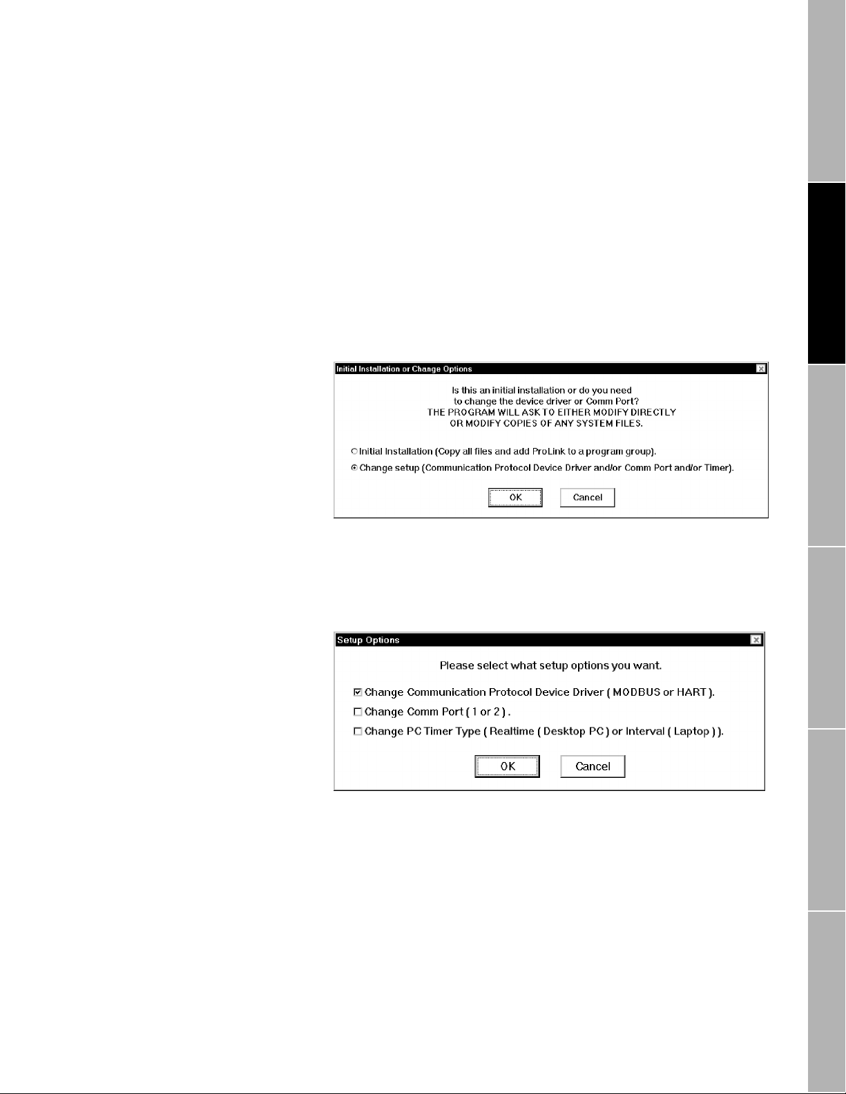
The Initial Installation or Change Options dialog box appears as shown
above.
The installation/setup program offers two options:
• Initial Installation, which installs the ProLink software and places
ProLink icons in a Windows program group.
• Change setup, which allows changes to device drivers for HART or
Modbus protocol and the communication port.
To install the ProLink software, select Initial Installation, then click OK.
Using ProLink® Software with Micro Motion® Transmitters
13
Page 28

continued
Getting Started
Installing the software
Installation Location dialog box
When the Installation Location dialog box appears as shown above,
enter the desired directory pathname, then click OK.
The installation/setup program creates the directory. As ProLink
program files are copied into the chosen directory, a "thermometer"
indicates the percentage of the installation that has been completed.
If a previous release of the ProLink program is installed on the
computer:
• The new program may be installed in the same directory as the
earlier version, or in a new directory. The new program files will
overwrite any default files that were created previously.
• The new program will use any configuration and default files that
were created using an earlier ProLink version. However , if the new
program is installed in a directory other than the default ProLink
directory, it will be necessary to locate configuration and default files
manually when using the new program.
Program Group dialog box
During software installation, the Select Program Group dialog box,
shown above, prompts the user to place the icons in a group window or
submenu named MMI, or in another group window or submenu.
Enter the name of the desired group window or submenu from the Start
menu in the text box, then click OK.
14
Using ProLink® Software with Micro Motion® Transmitters
Page 29

continued
Getting Started
Installing the software
Modify/Copy CONFIG.SYS dialog box
After the user specifies a Windows program group, the Modify or Copy
CONFIG.SYS dialog box appears as shown above. The choice
determines how device drivers are added to the personal computer
CONFIG.SYS file.
Select an option, then click OK.
• Select Add/Change to add the HART or Modbus device driver to the
CONFIG.SYS file in the root directory on the hard drive.
• Select Copy to copy the CONFIG.SYS file to the ProLink directory
before adding the appropriate device driver.
Communications Protocol dialog box
File Menu: Print File Menu: Log Files View Menu: VariablesBefore You Begin Getting Started File Menu: Database
After the user chooses how the installation/setup program modifies the
CONFIG.SYS file, the Communications Protocol dialog box appears as
shown above. The choice determines the protocol used by the software,
without affecting the protocol used by the PC Interface adaptor or the
connected transmitter.
Select either option, then click OK:
• Select HART or Modbus protocol if the PC Interface adaptor is
connected to an RFT9739.
• Select HART protocol if the PC Interface adaptor is connected to an
IFT9701, IFT9703, RFT9712, or an RFT9729.
Using ProLink® Software with Micro Motion® Transmitters
15
Page 30

continued
Getting Started
Installing the software
Communications Port dialog box
After ProLink software installation is completed, the ProLink Setup icon
enables switching of protocols used by the ProLink program. To change
the protocol used by:
• The ProLink program, see
Section 2.8
, page 22
• An RFT9739 transmitter, see the RFT9739 instruction manual
After the installation/setup program establishes the protocol that the
ProLink program will use, the Communications Port dialog box appears
as shown above. The dialog box prompts the user to choose COM1 or
COM2 as the communication port.
Select the desired option, then click OK, or, if the personal computer has
more than two serial ports, and a port other than COM1 or COM2 is
desired:
1. At the Communications Port dialog box, choose COM2.
2. After installation is completed, use the Windows Notepad program to
open and read the 3COM.TXT file (located in the INST subdirectory
of the ProLink directory). The 3COM.TXT file is an ASCII file that
explains how to modify the CONFIG.SYS file to designate COM3 or
COM4 as the communication port.
16
Using ProLink® Software with Micro Motion® Transmitters
Page 31

continued
Getting Started
Installing the software
Modify/Copy .INI files dialog box
After the user selects a communication port, the Modify or Copy WIN.INI
and SYSTEM.INI dialog box appears as shown above. The choice
determines how the installation/setup program modifies the personal
computer SYSTEM.INI and WIN.INI files to include the user-selected
communication port and display parameters specified in the installation
process.
Select an option, then click OK:
• Select Add/Change to add the communication port and display
parameters to the SYSTEM.INI and WIN.INI files in their default
directories on the hard drive.
• Select Copy to copy the SYSTEM.INI and WIN.INI files to the
ProLink directory before adding the communication port and display
parameters.
Setup Complete/Reboot dialog box
File Menu: Print File Menu: Log Files View Menu: VariablesBefore You Begin Getting Started File Menu: Database
After the user chooses how the installation/setup program modifies the
SYSTEM.INI and WIN.INI files, the Setup Complete dialog box appears
as shown above.
If CONFIG.SYS, SYSTEM.INI and WIN.INI files were copied during the
installation, copy them back to their default directories (e.g., using File
Manager or Windows Explorer), then reboot the computer.
• Copy the CONFIG.SYS file to the root directory.
• Copy the SYSTEM.INI and WIN.INI files to the Windows directory.
• It is necessary to reboot the computer to initialize changes made to
the CONFIG.SYS file.
Using ProLink® Software with Micro Motion® Transmitters
17
Page 32

Getting Started
Start-up
continued
2.6 Start-up
To run the ProLink program, select the MMI program group, then click on
the ProLink icon. In Windows 95, click the Start button, select Programs,
then select the MMI program group and click the ProLink icon. The
ProLink application window and Connect dialog box will be displayed, as
shown below.
In the ProLink application window:
• Labels for the File, Applications, Window, and Help menus appear
highlighted to indicate they can be accessed without a transmitter
connection, as shown below.
• Labels for the View, Configure, Calibrate, and Test menus appear
dimmed to indicate they are temporarily inaccessible, as shown
below.
• Press F1 for help at any time.
2.7 Connecting to the transmitter
18
Use the option buttons and text boxes in the Connect dialog box to
identify the transmitter by polling address or HART tag name, then click
OK.
• Under HART protocol, the connected RFT9739, RFT9712,
RFT9729, or IFT9701 can use the polling address or the (HART) tag
name.
• Under Modbus protocol, the connected RFT9739 must use a polling
address from 1 to 15.
To connect to the transmitter using its polling address:
1. Select Multidrop Address.
2. Enter the multidrop address, from 0 to 15 (1 to 15 for Modbus
protocol).
3. Click OK.
Using ProLink® Software with Micro Motion® Transmitters
Page 33

continued
Getting Started
Connecting to the transmitter
Menu bar
To connect to the transmitter using its HART tag name (HART
protocol only):
1. Select Tag Name.
2. Enter the transmitter tag name.
3. Click OK.
To view a list of available transmitters:
1. Select Poll Network.
2. Click Poll.
3. The network will be polled, and a drop-down list of available
transmitters is displayed, including addresses and HART tag names.
Select a transmitter, then click OK.
When a transmitter connection is established, all labels in the ProLink
menu bar are highlighted, as shown below, indicating the user can open
any menu.
Cannot Find message
If a connection with the transmitter cannot be made, the Cannot Find
dialog box appears, as shown above. Typical causes and appropriate
corrective actions are listed in
Table 2-2
.
Table 2-2. Troubleshooting the "cannot find" message
Status Cause Corrective Action
Transmit te r not receiving power Power OFF to transmitter Verify the transmitter is receiving supply
Power light on PC Interface adaptor is
OFF
Power OFF on PC Interface adaptor • Ensure selector switch on PC Interface
power (see the transmitter instruction
manual for troubleshooting instructions)
adaptor is set to either 202 or 485
• Ensure power cord is plugged into
power socket and firmly in place on PC
Interface adaptor, or install new 9-volt
battery
File Menu: Print File Menu: Log Files View Menu: VariablesBefore You Begin Getting Started File Menu: Database
Using ProLink® Software with Micro Motion® Transmitters
19
Page 34

continued
Getting Started
Connecting to the transmitter
Table 2-2. Troubleshooting the "cannot find" message
Status Cause Corrective Action
Transmit light on PC Interface adaptor
does not flash when trying to connect
to the tran s mitter
Transmit light on PC Interface adaptor
remains OFF, an d t he r eceive light
flashes while tr yi ng to connect to
transmitter
Transmit light on PC Interface adaptor
flashes while tr yi ng to connect to
transmitter using the Bell 202 physical
layer
Incorrect compu te r co m munication port • Change comm por t s w i th th e ProLink
Computer communication port (COMM1
or COMM2) is being used by another
program or device, such as a mouse,
fax, or modem
IRQ is being shared by ProLink and
another program or device, such as a
mouse, fax, or modem, which is using
communication port 3 (COMM3) or 4
(COMM4)
Windows 3.1 and ProLink time source in
conflict
Using wrong type of cable between the
computer and the PC Inter face adaptor
Conflict between physical layer settings Ensure that transmitter a nd position of
Improper wir in g bet we en PC Interface
adaptor and transmitter
Incorrect load resistance in wiring loop Ensure proper load in Bell 202 wiring
Incorrect communic at i on parameters Bell 202 requires HART
Noise on mA loop from an extern al
source
RFT9739 not properly configured for
Bell 202
RFT9712 or RFT 9729 not properl y
configured for Bell 202
Incompatible communication settings
between IFT9701/IFT9703 and ProLink
program
setup program
• Check cable connections between the
computer and the PC Interface adaptor
• Change co m m ports with the ProLink
setup program
• Disable device and remove other
conflicting comm drivers
Disable device and remove other
conflicti n g comm drivers
Change the time source from R eal Time
clock to Interval Timer with the ProLink
setup program
Use a straight through R S - 232 cable
from the computer to the PC Interface
adaptor
selector switch on PC Interface adaptor,
are all set to Bell 202
Ensure proper Bell 202 wi ring (see
“Wiring to the t ransmitter” on page 7)
loop (see “Wir i ng t o th e t ransmitter” on
page 7)
1200 baud, 1 stop bit, and odd parity
(see “Communicat io n opt i ons” on page
22, to change settings)
Ensure prope r re sistance in the Bell 202
wiring loop (see “Wiring to the
transmitter” on page 7)
Change RFT9739 settings (see the
instruction manual that was shipped with
the transmitter)
See the RFT9712 or RFT9729
instruction manual to verify:
• The commun icat i ons jumper located
on the processor board in the
RFT9712 or RFT972 9 is set to 268
• The RFT9712 or RFT9729 has
transmitter software version 5.0 or
higher
Ensure ProLink settings are configured
for HART protocol, 1200 baud, 1 stop bit,
250-600 ohm resist ance and odd parity
(see “Communicat io n opt i ons” on page
22)
®
protocol at
®
20
Using ProLink® Software with Micro Motion® Transmitters
Page 35

continued
Getting Started
Connecting to the transmitter
Table 2-2. Troubleshooting the "cannot find" message
Status Cause Corrective Action
Transmit light on PC Interface adaptor
flashes while tr yi ng to connect to
transmitter using the RS-485 physical
layer
Conflict between physical layer settings Ensure t hat transm i t t er a nd ProLink
Improper wir in g bet we en PC Interface
adaptor and transmitter
Incorrect communicati on parameters Verify that settings for protocol (HART or
Incorrect polling address Open the File menu, then choose
Baud rate too high for computer Change ProLink baud rate to 1200 baud,
RFT9739 not properly configured for
RS-485
RFT9712 or RFT 9729 not properl y
configured for RS-485
Noise interference Ensur e proper RS-485 wiring (see
setup, and position of selector switch on
PC Interface adaptor, are all set to
RS-485
• Ensure proper RS-4 85 wiring (see
“Wiring to the transmitter” on page 7)
• Verify terminal blocks are firmly seated
at transmitter and PC Interface adaptor
®
Modbus
bits are the same for the transmitter and
ProLink program
Connect. Click the Poll Network button in
the Connect dialog box, then choose Poll
for a list of available transmitters
then reset to higher rate is desired: Open
the File menu, then choose Comm
Options
Change RFT9739 settings (see the
instruction manual that was shipped with
the transmitter)
See the RFT9712 or RFT9729
instruction manual to verify:
• The communications jumper located
• The RFT9712 or RFT9729 is using
“Wiring to the t ransmitter” on page 7)
), baud rate, parity, and stop
on the processor board in the
RFT9712 or RFT9729 is set to 485
1200 baud for HART communication,
and has transmitter software version
5.0 or higher
File Menu: Print File Menu: Log Files View Menu: VariablesBefore You Begin Getting Started File Menu: Database
Windows® hour glass
When the Windows hour-glass symbol does not disappear, the ProLink
program has experienced a fatal error. Reboot the computer, then refer
Table 2-3
to
Using ProLink® Software with Micro Motion® Transmitters
for typical causes and appropriate corrective actions.
21
Page 36

continued
Getting Started
Communication options
Table 2-3. Additional ProLink troubleshooting information
Symptom Cause Corrective Action
Windows
disappear
®
hourglass symbol doe s not
Switch to another transmitter
Windows 3.1 and ProLink tim e source
are in conflict
Computer communication port (COMM1
or COMM2) is being used by another
program or device, such as a mouse,
fax, or modem
IRQ is being shared by ProLink and
another program or device, such as a
mouse, fax, or modem, which is using
communication port 3 (COMM3) or 4
(COMM4)
Change the time source from R eal time
clock to Interval timer with the ProLink
setup program
• Change co m m ports with the ProLink
setup program
• Disable device and remove any other
comm drivers
Disable device and remove any other
comm drivers
To switch to another transmitter, disconnect the transmitter connection.
Open the File menu, then choose Disconnect. The labels for the File,
Applications, and Help menus remain highlighted to indicate that they
are accessible without a connection.
During a work session, the user can repeatedly make or break
transmitter connections without closing the ProLink program.
2.8 Communication options
The ProLink installation/setup program makes changes to the
CONFIG.SYS file in the personal computer root directory and to the
SYSTEM.INI file in the Windows directory. These changes enable
communication between the personal computer and the connected
transmitter, and enable the user to poll devices on a multidrop network.
Transmitter communication options
If the Cannot Find dialog box appears (see page 19), the communication
options for the transmitter might be incompatible with communication
options for the ProLink software. In such situations, the user can enable
a software connection by changing the communication options for either
the transmitter or the ProLink software.
The transmitter has switches and jumpers that control the transmitter
baud rate, protocol, stop bits and parity. To set transmitter switches and
jumpers, see the transmitter instruction manual. Instructions for setting
communication options are unique for each RFT9739 version. Be sure
to use the instruction manual that was shipped with the transmitter.
22
Using ProLink® Software with Micro Motion® Transmitters
Page 37
continued
Getting Started
Communication options
Software communication options
After software installation is completed, communication protocols,
communication ports, and time source may be changed with the ProLink
installation/setup program. Communication options may then be
changed using the Configure Communications dialog box.
To change the configured ProLink communication setup:
1. Open the Windows Program Manager, open the MMI program group,
then double-click the ProLink Setup icon to run the ProLink setup
program. Windows 95 users select Programs from the Start menu,
then MMI (or the program group containing ProLink), then ProLink
Setup from the cascading menus.
2. When the Initial Installation or Change Options dialog box appears
as shown below, select Change setup.
3. When the Setup Options dialog box appears as shown below, select
one or more parameters to change. Click OK, then follow the
on-screen instructions to switch protocol, port, and/or PC timer
options.
4. After using the setup program:
a. If CONFIG.SYS, SYSTEM.INI and WIN.INI files were copied
during setup, use File Manager or Windows Explorer to copy
them back to their default directories.
-
Copy the CONFIG.SYS file into the root directory.
-
Copy the SYSTEM.INI and WIN.INI files into the Windows
directory.
5. Reboot the computer.
File Menu: Print File Menu: Log Files View Menu: VariablesBefore You Begin Getting Started File Menu: Database
Using ProLink® Software with Micro Motion® Transmitters
23
Page 38

continued
Getting Started
Communication options
6. Open the Windows Program Manager, open the MMI program group,
then double-click the ProLink icon to run the ProLink program.
Windows 95 users select Programs from the Start menu, then select
MMI (or the program group containing ProLink), then select ProLink
from the cascading menus.
7. Open the File menu, then choose Comm Options. The
Communication Options dialog box appears as shown in
Figure 2-7. Configure Communications dialog box
Figure 2-7
.
8. Open the Baud Rate list box to select a baud rate.
• Select 1200 baud for IFT9701, IFT9703, RFT9712, and RFT9729
transmitters.
• Select 1200 baud for RFT9739 transmitters configured for HART
Bell 202 communication.
• Select any baud rate for RFT9739 transmitters using HART or
Modbus RS-485 communication.
9. Comm Details shows the configured communications port and
communication hardware interrupt request line (IRQ). The port and
IRQ cannot be changed from the Configure Communications dialog
box, but must be configured in the ProLink setup routine. Follow
steps 1 through 3 to change the communications port and IRQ.
10.Select a Master Type option button. The available master types
depend on the protocol established when the software was installed:
• With the ProLink program configured for HART protocol (default),
select HART Primary or HART Secondary as the master type.
-
Select HART Primary to designate the ProLink program as the
primary master for the network. Choosing HART Primary
enables the ProLink program and a secondary master, such
as a Model 268 or 275, to communicate at the same time.
-
Select HART Secondary to designate the ProLink program as
the secondary master for the network. Choosing HART
Secondary enables a control system to serve as the primary
master.
24
Using ProLink® Software with Micro Motion® Transmitters
Page 39

Getting Started
Exit
continued
• With the ProLink software configured for Modbus protocol,
choose Modbus ASCII or Modbus RTU.
-
If Modbus RTU (default) is chosen, the ProLink program will
use the RTU data transmission mode (8 data bits).
-
If Modbus ASCII is chosen, the ProLink program will use the
ASCII data transmission mode (7 data bits). Choose this
option if the communication network cannot support binary
data.
11.For Windows 3.1 users only, Time Source shows whether the
ProLink software will use a real time clock or interval timer. The time
source cannot be changed from the Configure Communications
dialog box, but must be configured in the ProLink setup routine.
Follow steps 1 through 3 to change the time source configuration.
12.Use the Parity and Stop Bits option buttons to select the appropriate
parity and stop bits.
• Under HART protocol, the transmitter must use odd parity and
one stop bit.
• Under Modbus protocol, the transmitter can use odd parity, even
parity, or no parity, and either one or two stop bits.
13.Click OK when ready to accept the software communications
configuration.
2.9 Exit
To exit the ProLink program, open the File menu, then choose Exit. The
Exit ProLink dialog box appears, as shown below.
File Menu: Print File Menu: Log Files View Menu: VariablesBefore You Begin Getting Started File Menu: Database
• Select Yes to save the ProLink setup and communication options to
the PROLINK.INI file in the ProLink directory.
• Select No to exit without saving the ProLink setup and
communication options.
• Select Cancel to return to the ProLink program.
Using ProLink® Software with Micro Motion® Transmitters
25
Page 40

26
Using ProLink® Software with Micro Motion® Transmitters
Page 41

3 File Menu: Database
3.1 Overview
The Transmitter Database dialog box, shown in
enables storage, retrieval, transfer, and editing of transmitter
configurations. To open the Transmitter Database dialog box, open the
File menu, then choose Database.
The database contains transmitter configuration files in ASCII code.
A transmitter configuration file has an 8-character filename and a .CFG
extension. The default database includes one sample transmitter
configuration file for:
• the RFT9739 (samp9739.cfg)
• the IFT9701 (samp9701.cfg)
• the IFT9703 (samp9703.cfg)
• the RFT9712 and RFT9729 (samp9712.cfg)
The Transmitter Database dialog box operates in the connect mode and
the offline mode. The mode determines the tasks that the user can
perform.
To connect to the transmitter, open the File menu, then choose Connect.
When connected, the user can:
• Load a configuration file from the connected transmitter to the hard
drive or to a diskette.
• Send a configuration file from the hard drive or from a diskette to the
connected transmitter.
Figure 3-1
, page 28,
File Menu: Print File Menu: Log Files View Menu: VariablesBefore You Begin Getting Started File Menu: Database
To disconnect from the transmitter, open the File menu, then choose
Disconnect. When disconnected, the user can:
• Edit an existing configuration file.
• Save a configuration file to the hard drive or to a floppy diskette.
• Upload a Model 268 with an RFT9739, RFT9712, or RFT9729
configuration file (the ProLink program cannot be used with a Model
275 HART Communicator).
The user can remove a configuration file from the database at any time.
In the Transmitter Database dialog box, arrows and icons indicate the
direction of the transfer the ProLink program performs when a command
button is selected.
Using ProLink® Software with Micro Motion® Transmitters
27
Page 42

continued
File Menu: Database
File selection
Figure 3-1. Transmitter Database
dialog box
3.2 File selection
Directory list box
Use the Directory list box, Transmitter Configuration Files list box, and
File Name text box to select a file, then choose Load, Send, Offline,
Save, Upload, or Remove to transfer, edit, or erase the selected file.
The Directory list box lists directories on a specified hard drive or floppy
diskette. To change directories, click the Directory list box. The Change
Database Directory dialog box appears as shown in
1. Use the Drives list box in the Change Database Directory dialog box
to change drives. Open the drives list, then choose the desired drive.
2. Changing drives updates the Directories list box, which shows the
directories on the specified drive. Open folder icons appear beside
the active directory and its subdirectories. Select a directory, then
click OK.
3. Choosing OK returns the user to the T ransmitter Database dialog box
and updates the list of configuration files displayed in the Transmitter
Configuration Files list box.
Figure 3-2
.
28
Using ProLink® Software with Micro Motion® Transmitters
Page 43

continued
File Menu: Database
Database command buttons
Figure 3-2. Change Database
Directory dialog box
Transmitter configuration files list box
File name text box
3.3 Database command buttons
The Transmitter Configuration Files list box displays transmitter
configuration files in the active directory. Each file contains a partial or
complete configuration for an RFT9739, IFT9701, IFT9703, RFT9712, or
RFT9729.
Select a filename from the Transmitter Configuration Files list box. The
selected filename appears in the File Name list box.
Enter the name of a transmitter configuration file in the File Name text
box. The filename can include a DOS pathname, which overrides the
currently displayed drive and directory.
Create new configuration files by using Windows Explorer or File
Manager to copy an existing configuration file, which then can be
transferred or edited.
After selecting a configuration file, as described in
any active command button. Arrows and icons beside the command
buttons indicate the direction of the file transfer.
• From the transmitter, load the file to the hard drive or to a diskette.
• From the hard drive or from a diskette, send the file to the transmitter.
• From the hard drive or from a diskette, retrieve the file into the
ProLink database for offline editing.
• From the ProLink database, save the file to the hard drive or to a
diskette.
• From the hard drive or from a diskette, upload the file to a Model 268
(the ProLink program cannot be used with a Model 275 HART
Communicator).
• Erase (remove) the file from the ProLink database.
Section 3.2
, choose
File Menu: Print File Menu: Log Files View Menu: VariablesBefore You Begin Getting Started File Menu: Database
Using ProLink® Software with Micro Motion® Transmitters
29
Page 44

continued
File Menu: Database
Offline, save, and upload commands
3.4 Offline, save, and upload commands
Table 3-1. Items not saved or
restored with the
transmitter database
Before choosing Offline, Save or Upload, open the File menu, then
choose Disconnect.
• Choose Offline to edit an existing configuration file.
• Choose Save to save a configuration to the hard drive or to a
diskette.
• With software communication options set for HART primary at 1200
baud, choose Upload to upload a Model 268 with an RFT9739
version 2, RFT9712, or RFT9729 configuration file from the hard
drive or from a diskette. (The IFT9701 and IFT9703 transmitters are
not supported by the Model 268.)
Several RFT9739 configuration items are not saved or restored using
the Save and Upload commands. These items are listed in
Configuration items not saved with HART® or Modbus® protocols
Baud rate Milliamp output trim factors
Burst mode (ON or OFF) Modbus maximum integer
Communication prot ocol Modbus integer offsets
Convergence limit Modbus integer scale factors
External pressure transmitter polling* Multidrop/polling address
External pressure transmitter tag Number of data bits
HART unique ID (Long frame address) Number of HART response preambles
Maximum zeroing time Number of stop bits
Mechanical zero offset Parity
Mechanical zero standard deviation Sensor type*
*Saved with HART protocol; not saved with Modbus protocol
Table 3-1
.
Offline and save
Upload
To perform an offline configuration:
1. Select an existing configuration file for editing, then choose Offline to
highlight the Configure menu.
2. Open the Configure menu, then use its commands to access the
configuration dialog boxes. Follow the instructions in
(page 71) through
Chapter 13
(page 131) to edit the configuration
Chapter 8
file.
3. After changing the configuration, choose Save to save the edited file.
Uploading involves four separate procedures:
1. Connecting the PC Interface adaptor to a Model 268
2. Running the ProLink setup program to choose HART protocol (if not
already chosen)
3. Opening the Communication Options dialog box to choose 1200
baud and the HART primary master type (if not already chosen)
4. Choosing Upload in the Transmitter Database, then following the
on-screen instructions
After the Model 268 has been uploaded with the configuration file, the
configuration can be downloaded to a compatible transmitter. For
complete instructions for uploading and downloading with a Model 268,
and for transmitter compatibility, see
Appendix B
, page 171.
30
Using ProLink® Software with Micro Motion® Transmitters
Page 45

File Menu: Database
Load command
continued
3.5 Load command
Figure 3-3. File Overwrite dialog
box
Before choosing the Load command:
1. Open the File menu, then choose Connect.
2. Set the flow loop for manual operation.
To load a transmitter configuration into the ProLink database:
1. Open the File menu, then choose Database.
2. Select a file from the Transmitter Configuration Files list box, or type
a new configuration file name in the File Name text box. If desired,
click in the Directory box to change directories.
3. Choose Load to load the transmitter configuration into the
configuration file.
4. If the filename already exists, the Overwrite File dialog box appears,
as shown in
Choose Yes to proceed. The transmitter memory then overwrites the
selected configuration file.
After loading is completed, the user can access the configuration with
the ProLink program.
Figure 3-3
, before the configuration begins loading.
3.6 Send command
Before choosing the Send command:
1. Open the File menu, then choose Connect.
2. Set the flow loop for manual operation.
3. Make sure the transmitter memory and the source configuration file
have the same measurement units. Otherwise, the transmitter will
refuse the configuration.
If the source configuration file includes measurement units, follow these
steps to ensure they match the measurement units already stored in the
transmitter memory.
1. Set the control loop for manual operation.
2. Load the transmitter memory into the ProLink database as instructed
Section 3.5
in
3. Open the Configure menu, then choose Transmitter Variables.
4. In the Configure Transmitter Variables dialog box, use the Units list
boxes to change the measurement units so they match the units in
the source configuration, then click OK.
.
File Menu: Print File Menu: Log Files View Menu: VariablesBefore You Begin Getting Started File Menu: Database
Using ProLink® Software with Micro Motion® Transmitters
31
Page 46

File Menu: Database
Remove command
continued
To send a configuration file to the transmitter:
1. Open the File menu, then choose Connect.
2. Select the desired transmitter, then click OK.
3. Reopen the File menu, then choose Database.
4. Use the Transmitter Database dialog box to select the configuration
file to be sent to the transmitter, then choose Send.
3.7 Remove command
3.8 On-screen viewing of transmitter configuration files
Figure 3-4. Typical transmitter
configuration file
The user can erase (remove) configuration files with the ProLink
program in the connect or offline mode.
To remove a configuration file from the transmitter database:
1. Open File menu, the choose Database.
2. Select the configuration file to be erased, then choose Remove.
Use a text editor program, such as WordPad or Notepad, for on-screen
viewing of transmitter configuration files.
To view a transmitter configuration file:
1. Open a transmitter configuration file in WordPad or Notepad.
Transmitter configuration files are located in the default ProLink
directory, and are saved with a .CFG extension.
2. The chosen transmitter configuration file appears on screen as
depicted in
Figure 3-4
.
3.9 Exporting transmitter configuration files
32
Because transmitter configurations are stored as text files, they can
readily be imported into spreadsheets, word processors, and other
software applications. For more information about importing files, see
the documentation for the application that will receive the configuration.
Using ProLink® Software with Micro Motion® Transmitters
Page 47

4 File Menu: Print
4.1 Overview
4.2 Print setup
The File menu includes several commands used for retrieving process
information from one or more devices on a multidrop network and
sending the information to a printer or to an ASCII file. If the information
goes to a file, the data in the file can be imported into spreadsheets,
databases, word processors, and other software applications.
The File menu includes the following print commands:
• Choose Print Setup to define any number of tickets, which can
include data from transmitters and other HART 5.0 or higher revision
devices on a multidrop network. The ticket can go to a printer or to an
ASCII file.
• Choose Print to send one copy of a ticket to a printer or an ASCII file.
• Toggle the Interval Print command ON to send a ticket to the printer
or to the file at regular intervals controlled by the refresh rate.
• Choose Update Rate to set the print interval for tick e ts and the
update rate for all ProLink windows.
• Choose Print File to send a selected file to the connected printer.
Use the Print Setup/Ticket Builder dialog box to create a ticket definition
file. The ticket definition file specifies which transmitters the ProLink
program will poll, which data will be sent to the print ticket, and the
format of the print ticket.
Open the File menu, then choose Print Setup. The Print Setup/Ticket
Builder dialog box appears, as shown in
Figure 4-1
, page 34.
File Menu: Print File Menu: Log Files View Menu: VariablesBefore You Begin Getting Started File Menu: Database
The Print Setup/Ticket Builder dialog box allows the user to create a
ticket definition file with the following information:
Destination
•
may be sent to a printer or written to an ASCII file.
Transmitter Connections
•
polled. Up to 15 transmitters per ticket definition file can be specified.
Fields on Ticket
•
sent to the defined destination. A single ticket can include up to 100
data fields.
Separator
•
is used to separate fields in a file for importation into other software
applications (such as spreadsheets and databases).
Book Ends
•
each print cycle.
The user can define and store any number of ticket definition files. The
ProLink software saves ticket definition file names with a .TKT extension.
Using ProLink® Software with Micro Motion® Transmitters
determines where the polled data will be stored. Data
specify which transmitters are to be
specifies fields, for each transmitter, that are to be
defines the delimiter for fields on the ticket. The delimiter
define the text that will print at the beginning and end of
33
Page 48

continued
File Menu: Print
Print setup
Figure 4-1. Print Setup/Ticket
Builder dialog box
Select, edit, or create a ticket definition file
Figure 4-2. Ticket File Name
dialog box
The Ticket File text box shows the ticket definition file name.To select,
edit, or create a ticket definition file, other than the displayed definition:
1. Click the Ticket File text box. The ticket File Name dialog box
appears as depicted in
2. When the Ticket File Name dialog box appears:
• To select or edit an existing ticket definition file, select the desired
drive and directory, then double-click the desired filename.
• To create a new ticket definition file, select a drive and directory,
enter a new filename in the File Name text box, then click OK.
Figure 4-2
.
34
Using ProLink® Software with Micro Motion® Transmitters
Page 49

File Menu: Print
Print setup
continued
Destination
Transmitter connections
Destination options enable the ticket to go to a printer or to an ASCII text
file. If the ticket will go to a file, the user may name the ASCII text file that
will receive the data specified by the ticket definition.
Click an option button to choose a destination.
• If the ticket will go to an ASCII text file, enter the desired filename in
the text box. Do not enter a DOS pathname. Ticket text files are
saved to the default ProLink directory with a .TXT extension.
• If desired, column headings can be added to the ticket by selecting
the Use Column Headings checkbox. This option is overridden if
Field Name is chosen as a separator (see “Separator and book
ends” on page 37).
The Transmitter Connections list box displays all transmitter devices that
will be polled for the data to be printed on the ticket. The ticket definition
file may include up to 15 devices on a multidrop network, including the
currently connected transmitter.
• Under HART protocol, the currently connected transmitter can be
referred to as the special tag name "[CurCon]", as well as by its
established HART tag name or polling address.
• Under Modbus protocol, the currently connected transmitter can be
referred to by the special tag name "[CurCon]" or the polling address.
The first time a ticket is printed, the ProLink program checks for all
transmitter connections that are listed in the ticket definition file. If any
connection fails, the ticket will not print, and an error message will
appear. If the ticket definition file includes [CurCon], the ProLink program
must be in the connect mode.
File Menu: Print File Menu: Log Files View Menu: VariablesBefore You Begin Getting Started File Menu: Database
Figure 4-3. Add Transmitter Tag
dialog box
To add a device to the ticket definition file:
1. Choose Add in the Transmitter Connections frame. The Add
Transmitter Tag dia lo g box appears as shown in
Figure 4-3
.
Using ProLink® Software with Micro Motion® Transmitters
35
Page 50

File Menu: Print
Print setup
continued
2. At the Add Transmitter Tag dialog box, use the Tag Name option
buttons to select a device. If a device other than the connected
transmitter [CurCon] is selected, enter the polling address or HART
tag name in the text box. A device cannot be added to the ticket
definition file if a device with the same tag name already exists in the
file.
3. Use the Transmitter Type option buttons to specify one of three
available transmitter types:
• Select RFT9739 to poll for parameters available from an
RFT9739. When using Modbus protocol, select this option for all
devices on the ticket.
• Select RFT9712/9729/9739 to poll under HART protocol for
parameters common to all three transmitter models.
• Select IFT9701 to poll for parameters available from an IFT9701
or IFT9703.
• Select Other HART v.5 or higher to poll for parameters available
from transmitters or other devices that have HART 5.0 or higher
revision software.
4. Click OK to add the device to the ticket.
Fields on ticket
Figure 4-4. Edit Field Tag
Parameter dialog box
To remove a device from the ticket:
frame, select the device from the Tag Names list, then choose Remove.
When a device is removed from a ticket, the fields associated with the
device are also removed.
To add a parameter to a device on the ticket:
1. Choose Add in the Fields on Ticket frame. The Edit Field Tag
Parameter dialog box appears as shown in
2. Select a device from the Tag Name text box. Each device includes
the polling address or HART tag name, followed by the transmitter
type in brackets.
3. All the parameters available from the chosen device appear in the
Parameter list box. To add a parameter, select it, then click OK.
in the Transmitter Connections
Figure 4-4
.
36
Using ProLink® Software with Micro Motion® Transmitters
Page 51

File Menu: Print
Print setup
continued
In the Print Setup/Ticket Builder dialog box, the Fields on Ticket list box
shows parameters listed with alphanumeric codes.
• The polling address or tag name to the left of the decimal point
identifies the device that returns the parameter.
• The label to the right of the decimal point identifies the parameter.
Example:
Example:
Identify a parameter returned from an RFT9739 that has the HART tag
name ELITEFLO.
The Fields list box includes the following parameter:
ELITEFLO.216 MA_1_Var
The characters to the left of the decimal point indicate the HART tag
name (ELITEFLO). The digits to the right of the decimal point indicate
that the parameter is the primary milliamp output variable.
Identify a parameter returned from an RFT9712 that has 10 as its
polling address.
The Fields list box includes the following parameter:
10.171 Flow_Cal
The digits to the left of the decimal point indicate the polling address
(10). The digits to the right of the decimal point indicate that the
parameter is the flow calibration factor.
File Menu: Print File Menu: Log Files View Menu: VariablesBefore You Begin Getting Started File Menu: Database
To remove a parameter from a device on the ticket:
Ticket frame, select a parameter from the Fields list, then choose
Remove.
Separator and book ends
The Separator separates the various fields on the ticket. The user can
place any of the following separators between fields:
•A space
• A comma
• The field name (such as, "Mass_Flow =")
• A custom separator (such as ASCII characters, date, fieldname, etc.)
The separator should be selected based on the ticket destination.
• Select Field Name to print each field on a separate line (typically
used if the ticket destination is defined as Printer).
39 shows a typical ticket printed with the fieldname as the separator.
• For ASCII text files that will be imported into other software
applications, determine the appropriate separator by referring to the
instruction manual for the application into which the data will be
imported.
Using ProLink® Software with Micro Motion® Transmitters
In the Fields on
Figure 4-5
, page
37
Page 52

File Menu: Print
Print
continued
Click an option button to choose a separator. If Other is chosen, the user
can enter text as ASCII printable characters, and can also enter ASCII
decimal codes for nonprintable characters such as a carriage return
(013) or line feed (010). The ASCII character set is listed in
Appendix D
page 181.
Book Ends indicate the beginning and end of each print interval. Enter
characters for each book end as ASCII printable characters and/or
ASCII decimal codes.
To include the date, time, or fieldname as a separator or book end, enter
the following character strings:
\DATE
\TIME
\FIELDNAME
To enter the time, date, and fieldname on the same line with spaces
between them, enter a space before entering the next character string.
For example:
\DATE \TIME \FIELDNAME
,
4.3 Print
To enter ASCII decimal codes for nonprintable characters:
• Enter the 3-digit decimal code for each character. The ASCII
character set is shown in
Appendix D
.
• Enter a backslash character (\) before each 3-digit code.
• The ASCII codes for carriage return (013) and line feed (010)
separate lines of text in most software applications. To make a new
line, enter \013\010.
• To enter a backslash as a printable character, enter two backslash
characters (\\).
Figure 4-5
, page 39 shows a typical ticket printed with the leading book
end:
START TICKET \DATE \TIME
and the trailing book end:
END TICKET \013\010
The Print command sends one complete ticket to a printer or ASCII text
Figure 4-5
file.
depicts a simple ticket as it appears when the user
chooses the Print command.
• The ticket will print in accordance with the current ticket definition,
displayed in the Print Setup/Ticket Builder dialog box.
• To choose, edit, or create a ticket definition file, see
Section 4.2
,
page 33.
• To print a ticket, open the File menu, then choose Print.
38
Using ProLink® Software with Micro Motion® Transmitters
Page 53

continued
File Menu: Print
Interval print
Figure 4-5. Typical ticket printed using print command
Start ticket 7/10/96 3:25:15 PM
Mass_Flow = 21.9
Temp = 25.9
Dens = 0.04561
End ticket
4.4 Interval print
With Interval Print command toggled ON, the ProLink program sends
the ticket to the printer or ASCII text file at regular intervals. At each
interval, if the ticket goes to an ASCII text file, the new ticket appends to
the end of the existing file.
• The printer receives the ticket that is named in the Ticket File text box
of the Print Setup/Ticket Builder dialog box.
• To choose, edit, or create a ticket definition file, see
page 33.
To toggle the Interval Print command ON or OFF, open the File menu,
then choose Interval Print.
• If a checkmark appears beside the command line when the File
menu opens, choosing Interval Print toggles interval printing OFF.
• If the command line appears without a checkmark when the File
menu opens, choosing Interval Print toggles interval printing ON.
• Interval print is suspended while menus are open.
Figure 4-6
depicts a sample ticket as it appears when the user toggles
interval printing ON.
Figure 4-6. Typical ticket printed using interval print command
Start ticket 7/10/96 3:25:15 PM
Mass_Flow = 21.9
Temp = 25.9
Dens = 0.04561
End ticket
Section 4.2
,
File Menu: Print File Menu: Log Files View Menu: VariablesBefore You Begin Getting Started File Menu: Database
Start ticket 7/10/96 3:26:15 PM
Mass_Flow = 21.6
Temp = 25.9
Dens = 0.04561
End ticket
Start ticket 7/10/96 3:27:15 PM
Mass_Flow = 21.0
Temp = 25.9
Dens = 0.04561
End ticket
Using ProLink® Software with Micro Motion® Transmitters
39
Page 54

File Menu: Print
Update rate
continued
4.5 Update rate
Figure 4-7. Print - View -
Application - Update
Rate dialog box
Update Rate controls how often the ProLink program prints tickets and
updates on-line values of variables displayed in the View windows. See
Chapter 6
• The Window Update Rate is the number of seconds the program
waits before updating values displayed in the View windows.
• The Ticket Print Rate is the number of seconds the program waits
between each interval print.
The update rate is dependent on selected communication options such
as baud rate, computer performance, and number of parameters polled.
Therefore, the rate entered is a "minimum" value. The maximum value
that can be entered is 86,400 (equal to 24 hours).
Open the File menu, then choose Update Rate. The Update Rate dialog
box appears as shown in
then click OK. To update the displayed value as quickly as possible,
enter a value of zero in the Window Update Rate text box.
(page 47).
Figure 4-7
. Enter the desired rates in seconds,
40
Using ProLink® Software with Micro Motion® Transmitters
Page 55

File Menu: Print
Print file
continued
4.6 Print file
Figure 4-8. Select File To Print
dialog box
Use the Print File command to send a selected file to the configured
printer. File types include:
• Configuration files
• Ticket definition files
•Text files
• Log files
• Initialization files
•Data files
To print a file:
1. Open the File menu, then choose Print File. The Print File dialog box
appears as shown in
2. Select a file type from the drop-down list.
3. Select a drive and directory, then select a file to be printed.
4. When the desired file is listed in the File Name text box, choose Print
to send the file to the connected printer.
Figure 4-8
.
4.7 Exporting print ticket files to other software applications
File Menu: Print File Menu: Log Files View Menu: VariablesBefore You Begin Getting Started File Menu: Database
Because a print ticket text file contains data in ASCII code, the ticket or
individual fields from a ticket ASCII text file can be imported into
spreadsheets, databases, word processors, and other software
applications.
For more information about exporting data to other software
applications, see the documentation for the application that will receive
the data.
Using ProLink® Software with Micro Motion® Transmitters
41
Page 56

42
Using ProLink® Software with Micro Motion® Transmitters
Page 57

5 File Menu:
Error and Change Log Files
5.1 Error logging
An error log is a record of transmitter configuration changes, data entry
errors, faults, and changes in the operating condition of the flowmeter.
With error logging toggled ON, the ProLink program reports the selected
errors whenever they occur.
Figure 5-1
depicts a typical error log file.
Figure 5-1. Typical error log file
7/15/96 2:53:55 PM Transmitter Status Changed: POWER RESET Set
7/21/96 8:32:06 AM UPDATE: Error Sending Visc_Cal
7/30/96 0:58:30 PM UPDATE: Error Sending Slug_Duration
To set up an error log, open the File menu, then choose Error Log File.
The Error Log dialog box appears as shown in
Figure 5-2. Error Log dialog box
Figure 5-2
.
File Menu: Print File Menu: Log Files View Menu: VariablesBefore You Begin Getting Started File Menu: Database
Log file name
Using ProLink® Software with Micro Motion® Transmitters
In the Error Log dialog box, the Log File Name frame contains option
buttons and a text box, which enable the error log to go to a printer or to
an ASCII file. If the error log will go to a file, the text box indicates the
name the ASCII file that will receive the data in the log.
Click an option button to choose a destination. If the error log will go to
an ASCII file, enter a filename in the text box. A pathname may also be
entered. Log files are saved with a .LOG default extension.
43
Page 58

File Menu: Error and Change Log Files
Change logging
continued
Error log options
Use the Error Log Option check boxes to set the options for the error log
file. A check box indicating an active option contains an "X".
Click check boxes to toggle options ON or OFF.
Error log on
ON: The ProLink program reports errors whenever they occur. If the
user opens the File menu with error logging toggled ON, a
checkmark appears beside the Error Log File command line.
If Error Log is turned ON, the Transmitter Status window must be
active for faults to be properly logged. The window may be
minimized if desired, but no transmitter faults will be logged with
the window closed. To view the Status window, open the View
menu, then choose Transmitter Status.
OFF: The program does not report errors. With error logging toggled
OFF, the Error Log File command appears without a checkmark.
Clear error log file
ON: Each report erases the existing error log file and starts appending
the error log file.
OFF: Each report appends the error log file.
Log transmitter faults
ON: The ProLink program reports all changes that the user can
observe in the Status window.
OFF: The program does not report changes that the user can observe
in the Status window.
5.2 Change logging
Log communication errors
ON: The ProLink program reports communication errors between
ProLink and the slave device.
OFF: The program does not report data entry errors.
Log configuration errors
ON: The ProLink program reports all errors made during entry of data
into dialog boxes in the Configure menu.
OFF: The program does not report configuration errors.
A change log is a record of changes and data entry errors made in
dialog boxes in the Configuration menu. With change logging toggled
ON, if the user makes any changes or data entry errors while working in
the Configuration menu, the ProLink program updates the change log.
Figure 5-3
depicts a typical change log file.
44
Using ProLink® Software with Micro Motion® Transmitters
Page 59

continued
File Menu: Error and Change Log Files
Change logging
Figure 5-3. Typical change log file
7/15/96 5:47:06 PM XMTR_1 .Dens_A= 0.00110
7/15/96 5:47:06 PM XMTR_1 .Dens_B= 0.09980
7/15/96 5:47:06 PM XMTR_1 .Flow_Cal=0000.75.13
7/15/96 5:47:06 PM XMTR_1 .SlugLow= 0.0050
7/15/96 5:47:06 PM XMTR_1 .SlugHigh= 0.1000
7/15/96 5:47:09 PM UPDATE: Completed Successfully
7/15/96 5:48:21 PM XMTR_1 .Vol_Flow_Unit=USgpm
7/15/96 5:48:21 PM XMTR_1 .Visc_Unit=cP
7/15/96 5:48:21 PM XMTR_1 .DP_Unit=psi
7/15/96 5:48:21 PM XMTR_1 .Mass_Flow_Unit=kg/hr
7/15/96 5:48:21 PM XMTR_1 .Meter_Direction=Bi-Directional
7/15/96 5:48:26 PM UPDATE: Completed Successfully
7/15/96 5:49:51 PM XMTR_1 .Freq_Var=Volume Flow
7/15/96 5:49:51 PM XMTR_1 .Fault_Ind=Upscale
7/15/96 5:49:51 PM XMTR_1 .Slug_Duration=100.00
7/15/96 5:49:52 PM UPDATE: Error Sending Slug_Duration
7/15/96 5:50:54 PM XMTR_1 .mA_2_Zero= 0.00250
7/15/96 5:50:54 PM XMTR_1 .mA_2_Gain= 0.2500
7/15/96 5:50:54 PM XMTR_1 .mA_2_Damp= 8.00
7/15/96 5:50:54 PM XMTR_1 .mA_1_Damp= 2.00
7/15/96 5:50:5 5 UP DA TE : Co mp le te d Su cc es sf ul ly
To set up a change log, open the File menu, then choose Change Log
File. The Change Log dialog box appears as shown in
Figure 5-4
.
Figure 5-4. Change Log dialog box
Log file name
File Menu: Print File Menu: Log Files View Menu: VariablesBefore You Begin Getting Started File Menu: Database
In the Change Log dialog box, the Log File Name frame contains option
buttons and a text bo x, which enable the change log to go to a printer or
to an ASCII file. If the change log will go to a file, the text box indicates
the name the ASCII file that will receive the data in the log.
Click an option button to choose a destination. If the change log will go
to an ASCII file, enter a filename in the text box. A pathname may also
be entered. If no pathname is specified, the file will be saved in the
ProLink default directory.
Using ProLink® Software with Micro Motion® Transmitters
45
Page 60

Change log options
Use the Change Log check boxes to set the options for the change log
file. A check box indicating an active option contains an "X".
Click check boxes to toggle options ON or OFF.
Change log on
ON: The ProLink program reports configuration changes and data
entry errors whenever they occur . If the user opens the File menu
with change logging toggled ON, a checkmark appears beside
the Change Log File command line.
OFF: The program does not report configuration changes or data entry
errors. With change logging toggled OFF, the Change Log File
command appears without the checkmark.
Clear change log file
ON: Each report erases the existing change log file and starts
appending the change log file.
OFF: Each report appends the change log file.
Log configuration changes
ON: The ProLink program reports changes that the user enters into
the dialog boxes in the Configure menu.
OFF: The program does not report configuration changes.
Log update errors
ON: The ProLink program reports configuration errors that the user
enters into the dialog boxes in the Configure menu.
OFF: The program reports configuration changes, but does not report
configuration errors.
46
Using ProLink® Software with Micro Motion® Transmitters
Page 61

6 View Menu: Variables
6.1 Overview
6.2 Process variables window
The View menu opens windows rather than dialog boxes. Open the View
menu to read process variables, outputs, and flowmeter status
indicators.
• Choose Process Variables to read values of process variables.
• Choose Output Levels to read output levels and corresponding
output variables.
The flowmeter configuration determines the values of outputs displayed
in the Output Levels window. The update rate determines how often the
displayed values are updated.
RFT9739
With the ProLink program connected to an RFT9739, the process
variables window can indicate:
• Mass flow rate
•Mass total
• Mass inventory
• Volume flow rate
• Volume total
• Volume inventory
•Density
• Temperature
•Viscosity
• Differential pressure (DP)
File Menu: Print File Menu: Log Files View Menu: VariablesBefore You Begin Getting Started File Menu: Database
Indication of viscosity and differential pressure requires a DP cell that
measures pressure drop across the sensor.
Figure 6-1
IFT9701, IFT9703, RFT9712, and RFT9729
With the ProLink program connected to an IFT9701, IFT9703, RFT9712,
or RFT9729, the process variables window can indicate:
• Mass flow rate or volume flow rate
• Mass total (inventory) or volume total (inventory)
•Density
• Temperature
Figure 6-2
IFT9703.
RFT9712 or RFT9729.
Using ProLink® Software with Micro Motion® Transmitters
depicts the Process Variables window for an RFT9739.
depicts the Process Variables window for an IFT9701 or
Figure 6-3
depicts the Process Variables window for an
47
Page 62

continued
View Menu: Variables
Process variables window
Figure 6-1. Process variables window for RFT9739
Figure 6-2. Process variables window for IFT9701/IFT9703
Figure 6-3. Process variables window for RFT9712/RFT9729
48
Using ProLink® Software with Micro Motion® Transmitters
Page 63

View Menu: Variables
Output levels window
continued
6.3 Output levels window
RFT9739
With the ProLink program connected to an RFT9739, the Output Levels
window displays the following values:
• The 0-20 mA or 4-20 mA current level and corresponding flow rate,
density, temperature, differential pressure, or viscosity indicated by
milliamp output 1
• The 0-20 mA or 4-20 mA current level and corresponding flow rate,
density, temperature, differential pressure, or viscosity indicated by
milliamp output 2
• The frequency and corresponding flow rate indicated by the
frequency/pulse output
• The ON/OFF status of events, which can be tied to milliamp outputs
or to the 0/15 V control output
Figure 6-4
depicts the Output Levels window for an RFT9739.
IFT9701 or IFT9703
With the ProLink program connected to an IFT9701 or an IFT9703, the
Output Levels window displays the following values:
• The 4-20 mA current level and corresponding flow rate as indicated
by the milliamp output
• The frequency and corresponding totalizer value indicated by the
frequency/pulse output
Figure 6-5
(page 50) depicts the Output Levels window for an IFT9701
or IFT9703.
RFT9712 and RFT9729
With the ProLink program connected to an RFT9712 or RFT9729, the
Output Levels window displays the following values:
• The 4-20 mA current level and corresponding flow rate, density, or
temperature indicated by the milliamp output
• The totalizer value indicated by the frequency/pulse output
Figure 6-6
or RFT9729.
Figure 6-4. Output Levels window for RFT9739
File Menu: Print File Menu: Log Files View Menu: VariablesBefore You Begin Getting Started File Menu: Database
(page 50) depicts the Output Levels window f or an RFT9712
Using ProLink® Software with Micro Motion® Transmitters
49
Page 64

continued
View Menu: Variables
Copying displayed values to other software applications
Figure 6-5. Output Levels window for IFT9701 or IFT9703
Figure 6-6. Output Levels window for RFT9712/9729
6.4 Copying displayed values
to other software
applications
nch
Values from display boxes in the Process Var ia bles and Ou tput Levels
windows can be copied or linked to spreadsheets, databases, word
processors, and other software applications.
In the other application, the copied value can be pasted as ASCII text, or
linked to the ProLink window using a dynamic data exchange (DDE) link.
Links may be established from as many of the fields in the Process
Variables and Output Levels windows as desired.
50
After a DDE link is established, linked values are continuously updated
in the other application as long as the linked ProLink windows remain
open. The linked windows may be minimized, but when one is closed, all
DDE links from the closed window are broken. For information on
reestablishing DDE links, see the documentation for the other software
application.
Using ProLink® Software with Micro Motion® Transmitters
Page 65

continued
View Menu: Variables
Copying displayed values to other software applications
Figure 6-7. Copy or Link dialog
box
To copy or link text from the ProLink window:
move the mouse
pointer to the desired value. When the pointer changes to a cross hair
(+), click the mouse to copy the value. A Copy/Link dialog box appears
as depicted in
To paste ASCII text in another application:
Figure 6-7
. Choose OK to copy the value.
place the insertion point
where the text should be pasted in the document, then open the Edit
menu and choose Paste.
To establish a DDE link:
place the insertion point where the linked text
should be pasted in the document, then open the Edit menu and choose
Paste Special or Paste Link.
• After choosing Paste Special, choose Link as an option.
• Choosing Paste Link, if the option is available, automatically
establishes the DDE link.
Some software applications do not support DDE links. For more
information on linking data, see the documentation for the other software
application.
File Menu: Print File Menu: Log Files View Menu: VariablesBefore You Begin Getting Started File Menu: Database
Using ProLink® Software with Micro Motion® Transmitters
51
Page 66

52
Using ProLink® Software with Micro Motion® Transmitters
Page 67

7 View Menu: Status
7.1 Overview
The Status window indicates operating conditions. When used with tools
such as a digital multimeter (DMM), the transmitter diagnostic LED, and
fault output levels, the Status window facilitates flowmeter
characterization, calibration, testing, and troubleshooting.
To open the Status window, open the View menu, then choose
Transmitter Status. The Status window appears as depicted in:
Figure 7-1
•
Figure 7-2
•
Figure 7-3
•
The Status window has separate frames for critical, operational, and
informational indicators.
• Critical indicators are described in
• Operational indicators are described in
• Informational indicators are described in
for an RFT9739
for an IFT9701 or IFT9703
for an RFT9712 or RFT9729
Section 7.3
, page 56.
Section 7.4
Section 7.5
Configure Menu:
Characterize
Transmitter Variables
Configure Menu:
, page 62.
, page 66.
Status indicators aid in troubleshooting the flowmeter. When
troubleshooting, investigate critical indicators first, then check
operational and informational indicators.
• When an indicator switch is OFF, the accompanying message
appears dimmed.
• When an indicator switch is ON, the accompanying message
appears highlighted to indicate a particular condition.
When a status indicator switches ON, refer to
lists status indicators alphabetically and lists the pages where
troubleshooting procedures for each indicator are described. Use the
Status window, transmitter fault output levels, and a digital multimeter
(DMM) to troubleshoot the flowmeter.
Table 7-1
, page 54, which
CAUTION
During troubleshooting, the transmitter
could produce inaccurate flow signals.
• Set control devices for manual operation before
troubleshooting the flowmetering system.
• If terminal blocks or wiring are discon nected from the
transmitter during tr oubleshoo ting, cycle po wer t o the
transmitter after reconnecting terminal blocks or
wiring.
Transmitter Outputs
Configure Menu:
Transmitter Information
Configure Menu:
Configure Menu: EventsView Menu: Status
Using ProLink® Software with Micro Motion® Transmitters
53
Page 68

continued
View Menu: Status
Overview
Table 7-1. Status indicators
Status indicator pages Status indicator pages
Figure 7-1. Status window for RFT9739
0 deg cal failed . . . . . . . . . . . . . 57
200 deg cal failed . . . . . . . . . . . 57
Analog 1 fixed . . . . . . . . . . . . . . 64, 69
Analog 1 saturated . . . . . . . . . . 64
Analog 2 fixed . . . . . . . . . . . . . . 64, 69
Analog 2 saturated . . . . . . . . . . 64
Analog input error . . . . . . . . . . . 62
Analog output fixed . . . . . . . . . . 64, 69
Analog output saturated . . . . . . 64
Burst Mode . . . . . . . . . . . . . . . . 69
Calibration failure. . . . . . . . . . . . 57, 62
Calibration in progress. . . . . . . . 67
Data loss possible. . . . . . . . . . . 62
Density overrange . . . . . . . . . . . 57
Display readback error. . . . . . . . 70
Drive overrange. . . . . . . . . . . . . 57
(E)EPROM checksum . . . . . . . . 57
Error cleared . . . . . . . . . . . . . . . 70
Event 1 on . . . . . . . . . . . . . . . . . 70
Event 2 on . . . . . . . . . . . . . . . . . 70
Frequency output fixed . . . . . . . 69
Frequency output saturated. . . . 65
Frequency saturated . . . . . . . . . 65
Input overrange . . . . . . . . . . . . . 57
Mass flow overrange . . . . . . . . . 57
Not configured. . . . . . . . . . . . . . 57
Power reset . . . . . . . . . . . . . . . . 70
Pressure input failure. . . . . . . . . 62
RAM error . . . . . . . . . . . . . . . . . 57
Raw elec. zero overflow. . . . . . . 66
Raw flow overflow . . . . . . . . . . . 66
RTD failure. . . . . . . . . . . . . . . . . 57
RTI failure . . . . . . . . . . . . . . . . . 57
Security breach . . . . . . . . . . . . . 70
Sensor failure . . . . . . . . . . . . . . 57
Slug flow . . . . . . . . . . . . . . . . . . 63
Temperature overrange . . . . . . . 57
Transmitter failiure. . . . . . . . . . . 56
Transmitter initializing . . . . . . . . 67
Volume flow overrange . . . . . . . 57
Zero too high. . . . . . . . . . . . . . . 67
Zero too low. . . . . . . . . . . . . . . . 67
Zero too noisy . . . . . . . . . . . . . . 67
54
Using ProLink® Software with Micro Motion® Transmitters
Page 69

continued
View Menu: Status
Overview
Figure 7-2. Status window for IFT9701/IFT9703
Configure Menu:
Characterize
Transmitter Variables
Configure Menu:
Figure 7-3. Status window for RFT9712/RFT9729
Transmitter Outputs
Configure Menu:
Transmitter Information
Configure Menu:
Using ProLink® Software with Micro Motion® Transmitters
Configure Menu: EventsView Menu: Status
55
Page 70

View Menu: Status
Fault outputs
continued
7.2 Fault outputs
If a flowmeter failure occurs, transmitters produce fault outputs. Model
RFT9739, IFT9701, IFT9703, RFT9712, and RFT9729, produce
downscale or upscale outputs to indicate a fault. In addition, a Version 2
or earlier RFT9739 also has last measured value and internal zero fault
levels.
• To set downscale or upscale fault output levels for a Version 3
RFT9739, an IFT9701, an IFT9703, an RFT9712, or an RFT9729,
refer to the transmitter instruction manual.
• To set fault levels for a Version 2 or earlier RFT9739, open the
Configure menu, then choose Transmitter Outputs.
RFT9739
• Downscale: milliamp outputs go to 0 mA if they produce a 0-20 mA
current, or to 0-2 mA if they produce a 4-20 mA current;
frequency/pulse output goes to 0 Hz.
• Upscale: milliamp outputs go to 22-24 mA; frequency/pulse output
goes to 15-19 kHz.
• Last measured value (not available with V ersion 3 transmitters):
Outputs hold the values measured immediately before the fault
condition occurred.
• Internal zero (not available with Version 3 transmitters): Outputs
indicate a value of zero for the represented process variable.
IFT9701/IFT9703
• Downscale: The milliamp output goes to 2 mA; the pulse output goes
to 0 Hz.
• Upscale: The milliamp output goes to 22 mA; the pulse output goes
to 7200 Hz for version 1.2 and higher or 1200 Hz for lower versions.
7.3 Critical indicators
RFT9712/RFT9729
• Downscale: The milliamp output goes to 2 mA; the frequency/pulse
output goes to 0 Hz.
• Upscale: The milliamp output goes to 22 mA; the frequency/pulse
output goes to 11,520 Hz.
Critical indicators switch ON under the following conditions:
• Master reset defaults in transmitter software
• Transmitter failure
• Flow, temperature, or density outside sensor limits
• Faulty flowmeter wiring, cable, or connections
• Inappropriate density calibration factors
• Plugged or partially plugged flow tubes
• Loss of input signal (when pressure is enabled)
• Temperature calibration failed (RFT9712 and RFT9729 only)
• Data loss during configuration
56
Using ProLink® Software with Micro Motion® Transmitters
Page 71
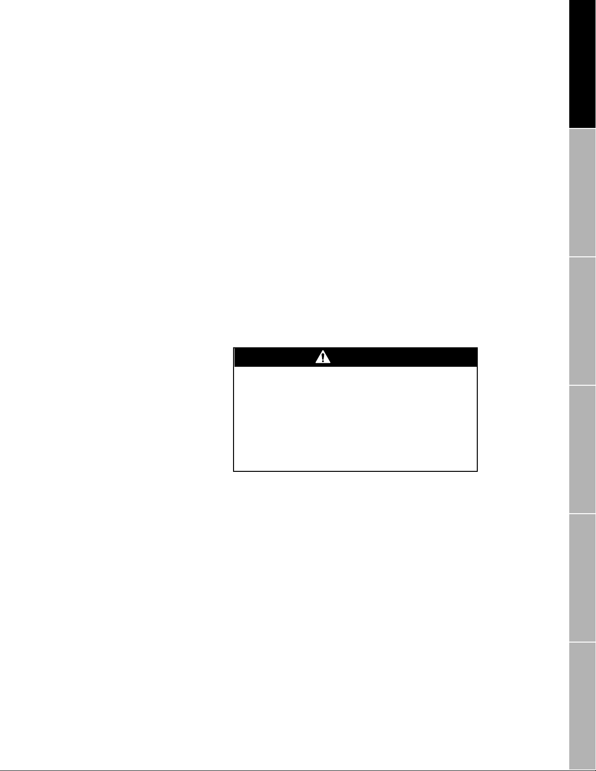
View Menu: Status
Critical indicators
continued
"Not Configured"
Transmitter failure indicators
If a master reset is performed on the transmitter, Not Configured
switches ON to indicate the flowmeter requires complete
characterization and reconfiguration. A master reset returns all
transmitter options to their default factory values.
• To perform a master reset, refer to the transmitter instruction manual.
• To characterize the flowmeter, open the Configure menu, then
choose Characterize. For more information about characterization,
Chapter 8
see
(page 71).
If one or more of the following indicators switches ON, a transmitter
failure has occurred:
• "Transmitter Failure"
• "(E)EPROM Checksum"
• "RAM Error"
•"RTI Failure"
• "0 Deg Cal Failure"
• "200 Deg Cal Failure"
If any of these errors occur, contact the Micro Motion Customer
Service department.
CAUTION
Configure Menu:
Characterize
Transmitter Variables
Configure Menu:
Sensor failure and overrange indicators
During troubleshooting, the transmitter could
produce inaccurate flow signals.
• Set control devices for manual operation before
troubleshooting the flowmetering system.
• If terminal blocks or wiring are discon nected from the
transmitter during tr oubleshoo ting, cycle po wer t o the
transmitter after reconnecting terminal blocks or
wiring.
If a sens or f a ilure occur s, if th e sen sor c ab le is f aul ty, or if m easur ed fl ow,
measured temperature, or measured density goes outside the sensor
limits, one or more of the following indicators switches ON:
• "Sensor Failure"
•"RTD Failure"
• "Drive Overrange"
• "Input Overrange"
• "Temperature Overrange"
• "Mass Flow Overrange"
• "Volume Flow Overrange"
• "Density Overrange"
Transmitter Outputs
Configure Menu:
Transmitter Information
Configure Menu:
Configure Menu: EventsView Menu: Status
Using ProLink® Software with Micro Motion® Transmitters
57
Page 72

View Menu: Status
Critical indicators
continued
To troubleshoot these status indicators, follow these steps:
1. Wiring problems are often incorrectly diagnosed as a faulty sensor.
At initial startup of the transmitter, alwa ys check the following:
a. Proper cable, and use of shielded pairs
b. Proper wire termination
• Wires on correct terminals
• Wires making good connections at transmitter terminals
Table 7-2
(
lists terminal designations for Micro Motion
sensors)
• Wires properly connected at any intermediate terminal
junction, such as the junction box between a Model DT sensor
and transmitter
2. For a Version 3 RFT9739, follow steps 2a through 2b. For earlier
versions, and for other transmitter models, go to step 3.
a. Open the Test menu, then choose Test Points. The Test Point
Diagnostics dialog box appears, as depicted in
Figure 7-4
, page
59.
b. Compare the displayed values with the values listed below and
proceed as follows:
• If the displayed drive gain exceeds 8 V, see
Table 7-3
, page
59 to troubleshoot the problem.
• If the displayed value for the left or right pickoff does not equal
approximately 0.0034 V per Hz, based on the displayed tube
frequency, go to step 3.
Table 7-2. Sensor and transmitter terminal designations
Transmitter terminals
Sensor
terminal
No connection 0 CN1-Z4 CN1-26d GD Black Shields
1 1 CN1-Z2 CN1-10d 1 Brown Drive +
2 2 CN1-B2 CN1-8d 2 Red Drive 3 3 CN1-B 6 CN1-14d 3 Orange Temperature 4 4 CN1-B 4 CN1-12d 4 Yellow Temperature
5 5 CN1-Z8 CN1-20d 5 Green Le ft pickoff +
6 6 CN1-Z10 CN1-24d 6 Blue Right pickoff +
7 7 CN-Z6 CN1-16d 7 Violet Temperature +
8 8 CN1-B10 CN1-22d 8 Gray Right pickoff 9 9 CN1-B8 CN1-18d 9 White Left pickoff -
RFT9739
field-mount,
RFT9712
RFT9739
rack-mount RFT9729
IFT9701 or
IFT9703
Wire color Function
lead length
compensator
58
Using ProLink® Software with Micro Motion® Transmitters
Page 73

continued
View Menu: Status
Critical indicators
Figure 7-4. Test Point Diagnostics dialog box
Table 7-3. Troubleshooting excessive drive gain
Configure Menu:
Characterize
Transmitter Variables
Configure Menu:
Symptom Cause Corrective action( s)
Drive gain
exceeds 8 V
Erratic process density ( sl ug f l ow) h as
caused flow tubes to vibrate erratically or
stop vibrating
Plugged flow tube Purge flow tubes
Cavitation or flashing of proces s flui d • If possible, increase inl et pressure and/or back pressure
• Drive board or m odu l e failure
• Cracked flow tube
• Sensor imbalance
• Monitor density
• Change sensor orientat io n
• If pump is mounted upstream from sensor, increase distance
between pump and sensor
Phone the Micr o Motion Customer Servic e De partment
3. Disconnect sensor wiring from the intrinsically safe transmitter
terminals (listed in
Table 7-2
resistance between wire pairs.
• If open or short circuits are found, or if measured resistance
values are outside the ranges listed in
sensor cable could be faulty. See
troubleshoot the problem.
• If faulty sensor cable is not indicated, go to step 4.
4. Before reconnecting wiring at the transmitter terminals, measure
resistance between wire pairs at the sensor junction box.
• If all me asured resistance values are wit hin the ranges listed in
Table 7-4
, page 60, either the process is outside acceptable
limits, or the flowmeter calibration needs to be changed. See
Table 7-5
, page 60, to troubleshoot the problem.
• If open or short circuits are found, either the sensor junction box
contains moisture, or the sensor is damaged. See
page 61, for corrective actions.
5. If troubleshooting fails to reveal why status indicators have switched
ON, phone the Micro Motion Customer Service Department for
technical assistance.
, page 58), then use a DMM to measure
Table 7-4
Table 7-5
, page 60, the
, page 60, to
Table 7-6
,
Transmitter Outputs
Configure Menu:
Transmitter Information
Configure Menu:
Configure Menu: EventsView Menu: Status
Using ProLink® Software with Micro Motion® Transmitters
59
Page 74

continued
View Menu: Status
Critical indicators
Table 7-4. Nominal resistance and voltage ranges for flowmeter circuits
Notes
• Temperature sensor value increases 0.38675 ohms per
°
C increase in temperature.
• Nominal resistance values will vary 40% per 100°C. However, confirming an open coil or shorted coil is more important
than any slight deviation from the resistance values presented below.
• Resistance across terminals 6 and 8 (right pickoff) should be within 10% of resistance across terminals 5 and 9 (left
pickoff).
• Resistance values depend on the sensor model and date of manufacture.
Circuit Wire colors Sensor terminals No rm al resistance range Normal voltage
Drive coil Brown to red 1 to 2 8 to 2650 ~8.0 V
Left pickoff Green to white 5 to 9 15.9 to 300 3.4 mV/Hz
Right pickoff Blue to gray 6 to 8 15.9 to 300 3.4 mV/Hz
Temperature sensor Orange to violet 4 to 7 100 Ω at 0
Lead length compensat or Yellow to viole t 4 to 7 100 Ω at 0
°
C + 0.38675 Ω / °C not applicable
°
C + 0.38675 Ω / °C not applicable
Table 7-5. Troubleshooting faulty sensor cable
Status indicators Resistance at transmitter terminals Cause Corrective action(s)
Sensor Failure
Input Overrange
Sensor Failure
Drive Overrange
Sensor Failure
Temperature Overrange
Sensor Failure
Input Overrange
Temperature Overrange
Drive Overrange
• Open or short from green to wh ite
• Open or short from blue to gray
Open or short from red to brown
• Open or short from violet to yellow
• Open or short from violet to orange
Resistance of any wire pair is outsi de
range listed in
Table 7-4
Faulty cable Repair or replace sensor
• Incorrect or fau lty cab le
connection
• Sensor failure
cable
Reconnect sensor cable
according to installation
instructions
60
Using ProLink® Software with Micro Motion® Transmitters
Page 75

continued
View Menu: Status
Critical indicators
Table 7-6. Troubleshooting overrange conditions
Status indicators
Sensor Failure
Input Overrange
Sensor Failure
Input Overrange
Zero Too Noisy
Sensor Failure
Drive Overrange
Sensor Failure
Drive Overrange
Input Overrange
Sensor Failure
Mass Flow Overrange
Volume Flow Overrange
Sensor Failure
Drive Overrange
Density Overrange
Sensor Failure
Temperature Overrange
Resistance at sensor
terminals Cause Corrective action(s)
Open or short from
green to white
Open or short from
blue to gray
V alues within ranges
listed in
page 60
Open or short from
red to brown
V alues within ranges
listed in
page 60
V alues within ranges
listed in
page 60
V alues within ranges
listed in
page 60
V alues within ranges
listed in
page 60
Open or short from
violet to yellow
Open or short from
violet to orange
Table 7-4
Table 7-4
Table 7-4
Table 7-4
Table 7-4
,
,
,
,
• Moisture in sensor case or
junction box
• Open or short left pickoff
• Moisture in sensor case or
junction box
• Open or short right pi ckoff
Transmitter cannot calculate
offset of flow signal
• Moisture in sensor case or
junction box
• Open or short drive coil
Flow rate outside sensor limit • Bring flow rate within sens or limit
,
Mass or volume flow rate outside
sensor limit
• Inappropriat e density f actors
• Process den si t y above 5 g/cc
for an RFT9739
• Process den si t y above 10 g/cc
for an RFT9712 or RFT9729
• Process den si t y above 2 g/cc
for an IFT9701 or IFT9703
• Erratic process density has
caused flow tubes to stop
vibrating
• Plugged flow tub e
Tempera ture outside sensor limit • Bring temperature w ith in sen sor
• Moisture in sensor case or
junction box
• Open or short lead length
compensator
• Moisture in sensor case or
junction box
• Open or short RTD
• If sensor junction box contains
moisture, check for leaking
junction box, conduit, or conduit
seals
• If sensor junction box does not
contain moistu re, re tu rn sensor to
factory
• Eliminate pipe stress, vibration, or
mechanical noise
• If using volume flow units, verify
density measureme nt
• Verify flow calibration
• Eliminate noise, then re -zer o
• Shut off flow, then re-zero
• If sensor junction box contains
moisture, check for leaking
junction box, conduit, or conduit
seals
• If sensor junction box does not
contain moistu re, re tu rn sensor to
factory
• Monitor flow rate
• If using volume flow units, verify
density measureme nt
• Verify flow calibration
• Perform density calibration or
density characterization
• Bring density withi n se nsor limit
• Monitor density
• Eliminate pipe stress, vibration, or
mechanical noise
• Purge flow tubes
limit
• Monitor temperature
• If sensor junction box contains
moisture, check for leaking
junction box, conduit, or conduit
seals
• If sensor junction box does not
contain moistu re, re tu rn sensor to
factory
Configure Menu:
Characterize
Transmitter Variables
Configure Menu:
Transmitter Outputs
Configure Menu:
Transmitter Information
Configure Menu:
Using ProLink® Software with Micro Motion® Transmitters
Configure Menu: EventsView Menu: Status
61
Page 76

continued
View Menu: Status
Operational indicators
"Analog Input Error" and "Pressure Input Failure"
"Data Loss Possible"
Analog Input Error applies only to versions 2.0 and higher RFT9739
transmitters. Analog Input Error switches ON when the pressure input to
the RFT9739 is less than 4 mA or greater than 20 mA, and indicates one
of the following conditions:
• Faulty wiring between a pressure transmitter and the RFT9739
• Pressure input requires characterization
Pressure Input Failure applies only to RFT9739 transmitters with
software versions 2.3 and higher. Pressure Input Failure switches ON to
indicate a loss of either the analog input signal, as above, or the HART
signal.
If Analog Input Error or the Pressure Input Failure switches ON:
• Characterize range limits for milliamp input
• Check for faulty wiring to or from pressure transmitter
• Alter fluid process
Data Loss Possible switches ON when a power fluctuation occurs during
transmitter configuration, to indicate the last configuration parameters
might not have been saved.
If Data Loss Possible switches ON, open the appropriate configuration
window and check the last parameters that were entered. Re-enter any
parameters that are not correct.
7.4 Operational indicators
"Calibration Failure"
Operational indicators switch ON to indicate the following conditions:
• The process is operating outside control limits.
• The transmitter cannot properly calculate settings during a
calibration procedure.
• Inappropriate measurement units or inappropriate limits on output
variables are driving outputs to their limits.
• The transmitter cannot calculate the flow rate.
Table 7-7
and lists appropriate corrective actions.
Calibration Failure switches ON if the transmitter cannot properly
calculate settings during a calibration procedure. The cause of the
failure depends on the type of calibration that is being performed:
• During auto zero, failure can occur due to mechanical noise from an
• During a two-point density calibration, failure can occur due to use of
For more information about flowmeter calibration, see
133).
summarizes conditions indicated by operational indicators,
external source or due to flow of fluid through the sensor.
a low-density fluid that is too dense, a high-density fluid that is not
sufficiently dense, or mechanical noise from an external source.
Chapter 14
(page
62
Using ProLink® Software with Micro Motion® Transmitters
Page 77

continued
View Menu: Status
Operational indicators
Table 7-7. Troubleshooting operational failures
Operational indicato r Cause Corrective actions
Slug Flow • Gas slugs causing process dens ity to
Frequency Saturated • Flow rate driving RFT9739 output from
Frequency Output Saturated Flow rate driving IFT9701 or IFT9703
Analog 1 Saturated • RFT97 39 output from PV+ and PV–
Analog 2 Saturated RFT9739 output from SV+ and SV–
Analog Output Saturated IFT9701 or IFT9703 milliamp output is 0
Raw Flow Overflow
Raw Elec. Zero Overflow
go below low slug flow limit
• Solids causing process density to go
above high slug flow limit
FREQ+ and RETURN terminals to 0 or
15 kHz
• Flow rate driving RFT9712 or RFT9729
frequency/pulse ou tp ut to 0 or 11 ,5 20
Hz
pulse output to 0 or 7200 Hz for versions
1.2 and higher, or 0 to 1200 Hz for lower
versions
terminals is 0, 2, or 22 mA
• RFT9712 or RFT9729 milliamp
output is 2 or 22 mA
terminals is 0, 2, or 22 mA
or 22 mA
Transmit te r cannot calculate flow rate Eliminate pipe stress, vibration, or mechanica l
• Open View menu, cho ose Process Variables
to monitor density
• Open Conf ig ur e m enu, cho ose Characterize,
enter new slug flow limits
• Open Conf ig ur e m enu, cho ose Transmitter
Outputs, enter new slug duration for Model
RFT9739
• Open Conf ig ur e m enu, cho ose Transmitter
Variables, change flow measurement units
• Open Conf ig ur e m enu, cho ose Transmitter
Outputs, rescale frequen cy/pulse output
• Reduce flow rate
• Open Conf ig ur e m enu, cho ose Transmitter
Outputs, change value of variable at 20 mA
• Alter fluid proc ess
noise
Configure Menu:
Characterize
Transmitter Variables
Configure Menu:
"Slug Flow"
Programmed slug flow limits enable transmitter outputs and the ProLink
Status window to indicate conditions such as slug flow (gas slugs in a
liquid flow stream or liquid in a gas stream). Such conditions adversely
affect sensor performance by causing erratic vibration of the flow tubes,
which in turn causes the transmitter to produce inaccurate flow signals.
If the fluid density goes outside the user-defined slug flow limits, all of
the following occur:
• The Slug Flow indicator in the ProLink Status window switches ON.
• Milliamp outputs go to 0 mA if they produce a 0-20 mA current, or to
4 mA if they produce a 4-20 mA current.
• Frequency/pulse output goes to 0 Hz.
• Flow totalization stops while the density reading is outside density
limits.
• The diagnostic LED on RFT9739 field-mount, IFT9701, IFT9703 ,
and RFT9712 transmitters blink OFF once per second (75% ON,
25% OFF).
• The flowmeter resumes normal operation when liquid fills the flow
tubes (when density stabilizes within the programmed slug flow
limits).
Transmitter Outputs
Configure Menu:
Transmitter Information
Configure Menu:
Configure Menu: EventsView Menu: Status
Using ProLink® Software with Micro Motion® Transmitters
63
Page 78

continued
View Menu: Status
Operational indicators
Analog and frequency saturated indicators
To program slug flow limits
Section 8 .5
see
1. Open the Configure menu, then choose Characterize.
2. In the Characterize Sensor dialog box, at the Low and High text
boxes in the Slug Flow Limits frame, enter the desired slug flow limits
in grams per cubic centimeter (g/cc).
3. Click OK.
In some applications, slug flow typically occurs for short periods of time.
If slug flow ceases in less than one minute, an RFT9739 can continue
holding the last accurately measured flow value until process density
stabilizes within the programmed slug flow limits. A user-defined slug
duration specifies the amount of time the RFT9739 indicates the last
measured flow value before indicating zero flow. (Some RFT9739
software versions cannot indicate last measured value.)
To program a slug duration for an RFT9739
more information,
1. Open the Configure menu, then choose Transmitter Outputs.
2. Enter the desired time, from 0.00 to 60.00 seconds, into the Slug
Duration text box.
3. Click OK.
If an output variable exceeds its upper range limit, a frequency saturated
or analog saturated indicator switches ON. The indicator can mean the
output variable has exceeded appropriate limits for the process, or the
user needs to change measurement units.
, page 81.
Section 10.5
, follow these steps. For more information,
, follow these steps. For
, page 116.
Analog output saturated
If Analog 1 Saturated, Analog 2 Saturated, or Analog Output Saturated
switches ON, open the View menu, then choose Output Levels to open
the Output Levels window.
If the output variable is outside control limits:
decrease the flow rate, density, temperature, or pressure of the fluid.
If the output variable is within control limits:
manual operation, then follow one of the procedures described below to
change the span of the milliamp output.
• Rescale the milliamp output by adjusting the 4 mA and/or 20 mA
range limit: Open the Configure menu, then choose Transmitter
Outputs. Low Limit, High Limit, and Minimum Span, displayed at the
bottom of the dialog box, indicate sensor limits in the measurement
units established for milliamp output variables.
-
The value entered into the 4 mA text box must be lower than the
value entered into the 20 mA text box.
-
The value entered into the 20 mA text box must be higher than
the displayed low limit and lower than the displayed high limit.
-
The difference between the values entered into the text boxes
must be greater than the displayed minimum span.
use a control device to
set the flow loop for
64
Using ProLink® Software with Micro Motion® Transmitters
Page 79

continued
View Menu: Status
Operational indicators
For more information about configuring transmitter outputs, see
Section 10
, page 107.
• If the milliamp output represents a flow rate, change the
measurement units for the flow rate: Open the Configure menu, then
choose Transmitter Variables. Choose a new unit of measure from
the units list box under Mass Flow or Volume Flow. For more
information about configuring measurement units and other
transmitter variables, see
Chapter 9
.
Configure Menu:
Characterize
Example:
Given:
An RFT9739 is configured to measure temperature in degrees
Celsius (°C). The milliamp output is configured so that 20 mA
represents 80°C. The milliamp output goes out of range (high) at 20
mA.
Problem:
When the process fluid temperature exceeds 80°C, the
milliamp (analog) output is saturated.
Solution:
temperature indicated by the output at 20 mA to 100
Change the span of the milliamp output. Increase the
°
C.
Frequency output saturated
If Frequency Output Saturated switches ON, open the View menu, then
choose Output Levels to open the Output Levels window.
If the flow rate is outside control limits:
use a control device to
decrease the flow rate.
If the flow rate is within control limits:
set the flow loop for manual
operation, then follow one of these procedures to change the span of the
frequency/pulse output:
• Rescale the frequency/pulse output: Open the Configure menu, then
choose Transmitter Outputs. Enter new values into the Frequency
and Rate text boxes . For more information about configuring
transmitter outputs, see
Chapter 10
.
• Change the measurement units for the flow rate: Open the Configure
menu, then choose Transmitter V ariables. Choose a new unit of
measure from the units list box under Mass Flow or Volume Flow . F or
more information about configuring measurement units and other
transmitter variables, see
Chapter 9
.
Transmitter Variables
Configure Menu:
Transmitter Outputs
Configure Menu:
Transmitter Information
Configure Menu:
Using ProLink® Software with Micro Motion® Transmitters
Configure Menu: EventsView Menu: Status
65
Page 80

continued
View Menu: Status
Informational indicators
Example:
"Raw Flow Overflow" and "Raw Elec. Zero Overflow"
7.5 Informational indicators
Given:
An RFT9739 is configured to indicate flow rate in pounds per
minute (lb/min). The frequency/pulse output has been scaled so that
100 Hz = 1 lb/min. The frequency/pulse output goes out of range at
15 kHz.
Problem:
frequency/pulse output is saturated.
Solution:
rescaling the frequency/pulse output so that 100 Hz = 2 lb/min (the
output will be saturated at 300 lb/min).
Raw Flow Overflow and Raw Elec Zero Overflow switch ON to indicate
the transmitter cannot calculate flow. If there are no open circuits in the
sensor wiring, the sensor is being subjected to mounting stress or
external noise.
If Raw Flow Overflow or Ra w Elec Zero Overflow s witches ON, eliminate
mounting stress on the sensor, and isolate the sensor from vibration and
mechanical noise.
Informational indicators switch on to indicate the following changes in
operating states:
• Transmitter start-up, calibration, zeroing, and testing
• Polling address other than 0 assigned to the transmitter for HART
• Cancel chosen during an output calibration or test
• Transmitter configured to send data in burst mode under HART
• An event assigned to an RFT9739 output achieves the setpoint
• An interru ption or error occurs in analog input
When the process flow rate exceeds 150 lb/min, the
Increase the flow rate represented by the output at 15 kHz by
communication in a Bell 202 multidrop network
protocol
66
Table 7-8
indicators.
, page 68 summarizes conditions indicated by informational
Using ProLink® Software with Micro Motion® Transmitters
Page 81

continued
View Menu: Status
Informational indicators
"Transmitter Initializing"
"Calibration In Progress"
Zero indicators
Transmitter Initializing switches ON to indicate transmitter self-calibration
in progress at start-up or after power cycling.
Calibration in Progress switches ON if the user performs a density
calibration or auto zero.
• For information about density calibration, see
Section 14.4
,
page 138.
• For information about auto zero, see
Section 14.3
, page 136.
Section 14.2
, page 133 and
Zero Too Noisy switches ON if mechanical noise prevents the transmitter
from setting an accurate zero flow offset during transmitter zeroing. If
auto zeroing fails, Calibration Failure switches ON in the Operational
frame of the Status window.
Zero Too High or Zero Too Low switches ON if flow is not completely
shut off during sensor zeroing, thereby causing the transmitter to
calculate a zero flow offset that is too high or too low to allow accurate
flow measurement.
For more information about transmitter zeroing, see
page 133 and
Section 14.3
, page 136.
Section 14.2
,
Configure Menu:
Characterize
Transmitter Variables
Configure Menu:
Transmitter Outputs
Configure Menu:
Transmitter Information
Configure Menu:
Configure Menu: EventsView Menu: Status
Using ProLink® Software with Micro Motion® Transmitters
67
Page 82

continued
View Menu: Status
Informational indicators
Table 7-8. Troubleshooting informational failures
Informational indicator Cause(s) Corrective action( s)
Pressure Input Failure No pressure input signal • Verify wiring to pressure transmitter
Transmitter Initializing Transmitter start-up/self-calibration in
Calibration
in progress
Zero Too Hi gh
Zero Too Low
Zero Too Noi s y Mechanical noise prevented accurate zero
Analog 1 Fixed
Analog Output Fixed
Analog 2 Fixed Communication failed during test or trim of
Frequency Output Fixed Commu ni ca tion failed during test of IFT9701
Burst mode Transmitter configured to send data in burst
Event 1 On Event 1 is ON • If totalizer assigned:
Event 2 On Event 2 is ON
Error Cleared Causes of errors have been corrected. Wait ten seconds
Power Reset • Power failure
Security Breach Security mode changed from mode 8 Re-enter securit y m ode 8 (see RFT9739
Display Readback Error Value written to display was not received If error does not clear itself in 60 seconds, cycle
progress
• Auto zero in progress
• Density calibration in progress
Flow not completely shut of f d uring auto zero Completel y shut off flow, then re-zero
Moisture in sensor ju n ct io n box caused zero
drift
flow setting during auto zero
• Communic at ion failed during test or trim of
milliamp output from RFT9739 PV+ and PV–
terminals
• Communic at ion failed during test or trim of
milliamp outp ut from RFT 9712, RFT9729, or
IFT9701 or IFT9703
Polling address of 1 to 15 assigned to
transmitter for HART Bell 202 communica t io n
milliamp output from RFT97 39 SV+ and SV–
terminals
or IFT9703 frequency out put
mode under HART protocol
• Brownout
• Pow e r cycling
• Disable pressure compensation
• If indicator switches OFF, no action
• If indicator remains ON, check flowmeter
cable
• If indicator switches OFF, no action
• If indicator remains ON:
-
Check flowmeter cable
-
Eliminate noise, then re-calibrate or r e- zero
Ensure interior of junction box is completely dry,
then rezero
Eliminate mechanical noi se if possible, then
rezero
Reconnect to transmitter, then reopen Milliamp
Test or Milliamp Trim dialog box and complete
test or trim
• Open Conf ig ur e m enu, cho ose Transmitter
Information, change polling address to 0
• For an RFT9739, RFT9712, or RFT9729, use
RS-485 communic at i on standard
Reconnect to transmitter, then reopen Milliamp
Test or Milliamp Trim dialog box and complete
test or trim
Reconnect to transmitter, then reopen
Frequency Test dialog box and compl et e t est
Open Configure menu, choose Transmitter
Information, switch burst mode OFF
-
Low alarm switches event ON at totalizer
reset
-
High alarm switches event OFF at totalizer
reset
• If other variable assigne d, event switches
ON/OFF when variable crosses setpoint
Check accuracy of totalizers
instruction manual for instructions)
power to the transmitter (turn power OFF, then
ON) to disable the display
68
Using ProLink® Software with Micro Motion® Transmitters
Page 83

continued
View Menu: Status
Informational indicators
Analog Fixed indicators
Analog 1 Fixed, Analog 2 Fixed, or Analog Output Fixed switches ON if
communication between the ProLink program and the transmitter is
interrupted during a milliamp output test or trim. The output remains
fixed at the assigned level until the trim or test procedure is completed.
• For more information about trimming milliamp outputs, see
Section 14.6
, page 151.
• For more information about testing milliamp outputs, see
Section 15.2
, page 156.
Analog 1 Fixed or Analog Output Fixed switches ON if the user assigns
a polling address other than 0 to the transmitter for HART
communication in a Bell 202 multidrop network. The output remains
fixed at 4 mA until the user assigns a polling address of 0 to the
transmitter. For RFT9739 transmitters using the RS-485 standard, the
primary milliamp output remains active.
To assign a polling address to the transmitter:
1. Open the Configure menu, then choose Transmitter Information.
2. Enter the desired polling address of 0 to 15 into the Comm Addr text
box in the Transmitter Database frame.
3. Click OK.
For more information about polling addresses, see
Section 11.2
,
page 121.
Configure Menu:
Characterize
Transmitter Variables
Configure Menu:
"Frequency Output Fixed"
"Burst Mode"
Frequency Output Fixed switches ON if communication between the
ProLink program and the transmitter is interrupted during a
frequency/pulse output test. The output remains fixed at the assigned
level until the test procedure is completed.
For more information about testing the frequency/pulse outp ut, see
Section 15.3
, page 157.
Burst Mode switches ON if the user configures the transmitter to send
data in burst mode while operating under HART protocol. In burst mode,
the transmitter bursts data at regular intervals.
To toggle burst mode ON or OFF:
1. Open the Configure menu, then choose Transmitter Information.
2. Select ON or OFF at the Burst Control option buttons.
3. Click OK.
For more information about burst mode, see
Section 11.4
, page 124.
Transmitter Outputs
Configure Menu:
Transmitter Information
Configure Menu:
Configure Menu: EventsView Menu: Status
Using ProLink® Software with Micro Motion® Transmitters
69
Page 84

continued
View Menu: Status
Informational indicators
Event indicators
"Error Cleared"
"Power Reset"
With flow, density, temperature, pressure, or assigned to an RFT9739,
RFT9712, or RFT9729 event, Event 1 or Event 2 switches OFF or ON
whenever the process variable crosses the setpoint.
With mass total or volume total assigned to an event, Event 1 or Ev ent 2
switches ON and OFF according to the low or high configuration of the
alarm.
• With a low alarm, Event 1 or Event 2 switches ON when the user
resets the totalizer.
• With a high alarm, Event 1 or Event 2 switches OFF when the user
resets the totalizer.
For more information about configuring events, see
Error Cleared switches ON for 1 second after other indicators in the
Status window have switched OFF. Error Cleared switches OFF when
the user closes the Status window .
Power Reset switches ON after a power failure, brownout, or power
cycle has interrupted operation of the transmitter. The transmitter has a
nonvolatile memory, which remains intact despite power interruptions.
Chapter 12
.
"Security Breach"
"Display Readback Error"
Security Breach applies only to Version 3.0, 3.5, and 3.6 RFT9739
transmitters. Security Breach switches ON to indicate the transmitter
security mode has been changed from security mode 8. Clear the
message by re-entering security mode 8 or by performing a master
reset.
For more information about RFT9739 security modes, or to perform a
master reset, refer to the transmitter instruction manual.
Display Readback Error applies only to Version 3.0, 3.5, and 3.6
RFT9739 transmitters with a local display. Display Readback Error
switches ON to indicate the value written to the transmitter display was
not properly received by the transmitter display.
If the error does not clear itself within 60 seconds, cycle power to the
transmitter (turn power OFF, then ON) to disable the display. Contact the
factory to replace a faulty display.
70
Using ProLink® Software with Micro Motion® Transmitters
Page 85

8 Configure Menu: Characterize
8.1 Overview
CAUTION
Failure to set con trol de vices fo r manual operation
before characterization could cause transmitter
output error.
Before opening the File, Configure, Calibrate, or
Applications menus, set process control devices for
manual operation.
Whenever a dialog box such as the one depicted
below appears, isolate the transmitter from devices
that used transmitter outputs fo r pro ces s co ntro l, th en
choose Yes.
Configure Menu:
Characterize
Transmitter Variables
Configure Menu:
The Characterize Sensor dialog box contains text boxes for entry of
factors that describe sensor sensitivity to flow and density.
• The flow calibration factor describes a particular sensor's sensitivity
to flow.
• Density factors describe a particular sensor's sensitivity to density.
• Slug flow limits set the density at which flow outputs indicate zero
flow due to slug flow (slugs of gas in a liquid flow stream).
For RFT9739 transmitters, the ProLink program also supports entry of
factors used for calculating temperature and pressure.
• The temperature calibration factor describes the slope and offset of
the equation used for calculating temperature.
• The viscosity calibration factor describes the slope or the slope and
offset of the equation used for calculating viscosity.
• For a Version 2 or later model RFT9739, the pressure compensation
parameters compensate for the pressure effect on sensor flow tubes.
Transmitter Outputs
Configure Menu:
Transmitter Information
Configure Menu:
Configure Menu: EventsView Menu: Status
Using ProLink® Software with Micro Motion® Transmitters
71
Page 86

continued
Configure Menu: Characterize
Overview
To open the Characterize Sensor dialog box, open the Configure menu,
then choose Characterize. The Characterize Sensor dialog box appears
as depicted in:
Figure 8-1
•
Figure 8-2
•
Values entered during sensor characterization override existing flow,
density, temperature, and viscosity factors, and change the flowmeter
calibration.
While characterizing the sensor, record factors in the appropriate
Transmitter Configuration Worksheet, shown in
for an RFT9739
for an IFT9701, IFT9703, RFT9712, or RFT9729
Figure 8-1. Characterize Sensor dialog box for RFT9739
Appendix E
.
Figure 8-2. Characterize Sensor dialog box for IFT9701/IFT9703 or RFT9712/RFT9729
72
Using ProLink® Software with Micro Motion® Transmitters
Page 87

Configure Menu: Characterize
Flow calibration factor
continued
8.2 Flow calibration factor
Sensor and transmitter shipped together
The flow calibration factor describes a particular sensor's sensitivity to
mass flow. Testing conducted in the Micro Motion flow calibration
laboratory determines the precise value of the flow calibration factor for
each sensor. (For an RFT9739, IFT9701, IFT9703, RFT9712, or
RFT9729 that is shipped without a sensor, the default value — which
must be changed — is 1.00005.13).
The first five digits and first decimal point
are the flow rate, in grams
per second, required to produce one microsecond of time shift between
velocity signals transmitted by sensor pickoff coils. In the default
calibration factor above, the first five digits and first decimal point
indicate that, for every detected microsecond of time shift, 1.0000 grams
of fluid per second flow through the sensor.
The last three digits and second decimal point
represent the
temperature coefficient for the sensor. The temperature coefficient
represents the percent change in the rigidity of the flow tubes around the
twisting axis per 100
°
C.
If the sensor and transmitter were ordered together as a Coriolis
flowmeter, the correct flow calibration factor was programmed into the
transmitter at the factory and does not need to be changed.
After calibration at the factory, the value displayed in the FlowCal text
box is the same as the flow cal factor on the sensor serial number tag
and the flowmeter calibration certificate, which is shipped with the
sensor.
Configure Menu:
Characterize
Transmitter Variables
Configure Menu:
Transmitter Outputs
Configure Menu:
Model RE-01 Remote Electronics Unit replaced in the field
With a Version 3.0, 3.5, or 3.6 RFT9739, a meter factor is available,
which adjusts the flowmeter measurement without modifying the flow
calibration factor. For information on meter factors, see
Chapter 13
.
Model RFT9739, IFT9701, IFT9703, RFT9712, and RFT9729
transmitters use the flow calibration factor in calculating mass flow rate.
The Model RE-01 Remote Electronics Unit uses a sensor sensitivity
factor.
If an RE-01 is being replaced by another transmitter:
1. Use the following equation to derive the first five digits of the flow
calibration factor from the RE-01 flow sensitivity factor:
1.507 Flow Sensiti v ity Factor
×
2. Use the appropriate value from
Table 8-1
for the last three digits of
the flow calibration factor.
Transmitter Information
Configure Menu:
Configure Menu: EventsView Menu: Status
Using ProLink® Software with Micro Motion® Transmitters
73
Page 88

continued
Configure Menu: Characterize
Flow calibration factor
Table 8-1. Temperature coefficients for flow
Sensor model Coefficient Sensor model Coefficient
CMF010HP, high pressure 2.88
CMF010M, stainless 4.26
CMF010N, Inconel
CMF025M, stainless 4.75
CMF025H, Hastelloy
CMF050M, stainless 4.75 D600, serial number above 214724 4.50
CMF050H, Hastelloy 2.90 F025, stainless 4.65
CMF100M, stainless,
serial number below 357341 4.75 F050, stainless 4. 77
CMF100M, stainless,
serial number equal to or above 357341 4.26 F100, stainless 4.32
CMF100H, Hastelloy,
serial number below 357341 2.90 F200, stainless 4. 29
CMF100H, Hastelloy,
serial number equal to or above 357341 2.79 R025, stainless 4.65
CMF200M, stainless,
serial number below 332683 4.75 R050, stainless 4.50
CMF200M, stainless,
serial number equal to or above 332683 4.26 R100, stainless 4.67
CMF200H, Hastelloy,
serial number below 332683 2.90 DL025, Tantalum
CMF200H, stainless,
serial number equal to or above 332683 2.79 DS012, Tantalum 2.18
CMF300M, stainless,
serial number below 332692 4.75 DL050, Tantalum 2.18
CMF300M, stainless,
serial number equal to or above 332692 4.26 DX025, stainles s 4. 26
CMF300H, Hastelloy,
serial number below 332692 2.90
CMF300H, Hastelloy,
serial number equal to or above 332692 2.79
CMF300A 4.26
CMF400 3.89
®
®
2.79
2.90
D sensor, stainless,
serial number equal to or below 214724 5.13
D sensor, stainless,
serial number above 214724 4. 26
D sensor, Hastelloy,
serial number equal to or below 214724 3.15
D sensor, Hastelloy,
serial number above 214724 2. 79
D600, serial number
equal to or below 214724 4.70
®
2.18
74
Using ProLink® Software with Micro Motion® Transmitters
Page 89

Configure Menu: Characterize
44.5 1.507⋅67.062=
Flow calibration factor
continued
Example:
Given:
A D100 sensor with 316L stainless steel flow tubes, originally
calibrated with an RE-01, has a sensitivity factor of 44.5.
Problem:
The RE-01 has been replaced by an RFT9739. A flow
calibration factor must be programmed into the new transmitter.
Solution:
The first five digits of the flow calibration factor are calculated
from the RE-01 flow sensitivity factor, as f ollows:
The appropriate value for a D100 sensor with 316L stainless steel flow
tubes is:
5.13
The complete flow calibration factor is
67.0625.13
3. Perform this step only if the following conditions are true:
• The transmitter is an RFT9739 with software version 2.4 or higher
(all RFT9739 transmitters shipped after April 1995 have software
version 2.4 or higher); and
• The sensor is an older Model D or DL sensor, with a serial
number of 87263 or lower (shipped before November 1986)
Configure Menu:
Characterize
Transmitter Variables
Configure Menu:
Transmitter Outputs
Configure Menu:
CAUTION
Failure to properly characterize a Model D or DL
sensor with a copper RTD will cause
measurement error.
If the sensor has a copper RTD, the flow calibration
factor programmed into the transmitter must be
modified as described below, to ensure accurate flow
measurement.
a. Contact the factory to identify the sensor's RTD type.
b. If the sensor has a copper RTD, modify the temperature
coefficient from step 2, by replacing the decimal point with the
letter "c". For example, change "5.13" to "5c13".
Transmitter Information
Configure Menu:
Configure Menu: EventsView Menu: Status
Using ProLink® Software with Micro Motion® Transmitters
75
Page 90

Configure Menu: Characterize
Flow calibration factor
continued
Sensor or transmitter replaced in the field
Field flow-calibration
If the sensor or transmitter is replaced in the field, the user must
re-characterize the transmitter by programming the new sensor flow
calibration factor into the transmitter. (For an RFT9739, IFT9701,
IFT9703, RFT9712, or RFT9729 that is shipped without a sensor, the
default value — which
To characterize the transmitter for flow measurement:
• Enter the flow calibration factor (eight digits and two decimal points)
from the sensor serial number tag — this is the preferred method;
or
• Enter the flow calibration factor (eight digits and two decimal points)
from the calibration certificate that was shipped with the sensor.
Flow calibration is performed at the factory to NIST (National Institute of
Standards and Technology) standards. If, after characterizing the
transmitter for flow as described above, the meter fails to perform within
the accuracy specifications provided by Micro Motion, it might be
necessary to perform a field flow-calibration or, for a Version 3.0, 3.5, or
3.6 RFT9739, to adjust the meter factor (see
If a field flow-calibration is performed, and the transmitter is an RFT9739
using a pressure input for pressure compensation, the user should enter
the calibration pressure in the FlowCal Pressure text box. Enter the
value in psi. For more information on pressure compensation, see
Section 8.7
, page 86.
must
be changed — is 1.00005.13).
Chapter 13
).
In the flow calibration procedure, a batch of fluid is run through the
sensor, then the weighed amount of fluid in the batch is compared with
the measured amount of fluid indicated in the Totalizer Control dialog
box. To perform a flow calibration, follow these steps:
1. Set process control devices for manual operation.
2. For an IFT9701, IFT9703, RFT9712, or RFT9729, if the application
requires volume flow measurement, choose a mass flow unit for the
flow calibration, then choose a volume flow unit for the application
after the calibration is complete. The flow calibration factor will be the
same regardless of the mass flow unit that is chosen.
To select a mass flow unit:
a. Open the Configure menu, then choose Transmitter Variables.
b. When the Configure Transmitter Variables dialog box appears,
open the Units list box under Mass/Volume Flow (for an IFT9701
or IFT9703) or Mass Flow (for an RFT9712 or RFT9729) to select
a standard engineering mass flow unit.
For more information about configuring flow units, see
page 93.
Section 9.2
,
76
Using ProLink® Software with Micro Motion® Transmitters
Page 91

Configure Menu: Characterize
Flow calibration factor
continued
3. For a Version 3.0, 3.5, and 3.6 RFT9739, ensure the mass-flow
meter factor is
1.0000
. To check the meter factor, open the Configure
menu, then choose Meter Factors to open the Meter Factors dialog
box. Change the mass-flow meter to 1.0000 if any other value is
displayed.
4. Enter the flow calibration factor (eight digits and two decimal points)
into the FlowCal text box.
• Enter the flow calibration factor from the sensor serial number tag
— this is the preferred method;
or
• Enter the flow calibration factor from the calibration certificate that
was shipped with the sensor.
5. Zero the flowmeter. The zeroing procedure is described in
Section 14.2
, page 133.
6. Open the Applications menu, then choose Totalizer Control or
IFT9701/IFT9703 Totalizer Control (for an IFT9701 or IFT9703).
Choose Reset to reset the internal totalizer to zero.
7. Run three batches of fluid, resetting the scale and totalizer between
batches. For each batch, record the weights indicated by the scale
and the totalizer.
Weight
scale
Weight
flowmeter
First batch
Second batch
Configure Menu:
Characterize
Transmitter Variables
Configure Menu:
Transmitter Outputs
Configure Menu:
Third batch
Total
8. Divide
Total Weight
scale
by
Total Weight
. This is the mass-flow
flowmeter
meter factor. Record the meter factor.
Mass-flow meter factor
9. For a Version 3.0, 3.5, or 3.6 RFT9739, the mass-flow meter factor
may be entered into the transmitter as an alternative to completing
this procedure. The meter factor adjusts the flowmeter measurement
without modifying the flow calibration factor.
• To enter the meter factor, open the Configure menu, then choose
Meter Factors to open the Meter Factors dialog box. After
entering the meter factor , it is not necessary to perform steps 10
through 12 of this procedure.
• For information on meter factors, see
Chapter 13.
Transmitter Information
Configure Menu:
Configure Menu: EventsView Menu: Status
Using ProLink® Software with Micro Motion® Transmitters
77
Page 92

Configure Menu: Characterize
Density factors for RFT9739
continued
10.Multiply the meter factor from step 8. This is the mass-flow meter
factor. Record the meter factor. by the first five digits of the current
flow calibration factor. This is the first five digits of the new flow
calibration factor.
Mass-flow meter factor
11.Open the Configure menu, then choose Characterize to open the
Characterize Sensor dialog box. Enter the new flow calibration factor
in the FlowCal text box. The complete flow calibration factor should
have eight digits and two decimal points.
-
Enter the value from step 10 as the first five digits and first decimal point.
-
For the last three digits and second decimal point, enter the last
three digits and decimal point from the flow calibration factor
entered in step 4.
12.To verify the accuracy of the new flow calibration factor, repeat
step 7. The amount of fluid indicated in the Totalizer Control dialog
box should equal the weighed amount of fluid in the batch, within
accuracy specifications provided by Micro Motion for the flowmeter.
8.3 Density factors for RFT9739
Density factors describe a particular sensor's density measurement
sensitivity. Testing conducted in the Micro Motion Flow Calibration
Laboratory determines the precise values of the density factors for each
sensor.
The RFT9739 uses six separate factors to calculate density:
Dens A
•
is the density, in grams per cubic centimeter, at line
conditions, of the low-density material used during a two-point
density calibration.
Dens B
•
is the density, in grams per cubic centimeter, at line
conditions, of the high-density fluid used during a two-point density
calibration.
K1
•
is the tube period, in microseconds, adjusted to 0
°
C, when the
flow tubes contain the Dens A calibration fluid at line conditions.
K2
•
is the tube period, in microseconds, adjusted to 0
°
C, when the
flow tubes contain the Dens B calibration fluid at line conditions.
FD
•
(or
K3)
accounts for the effect of high flow rate on the density
measurement, and usually is not required. The FD and K3 factors
can be stored in, and viewed from, the ProLink transmitter
configuration file. The FD or K3 density calibration procedure is
described in
Temp Coeff
•
Section 14.4
, page 138.
, the temperature coefficient for density, represents the
percent change in the elasticity of the flow tubes around the bending
axis, and the corresponding change in tube period, per 100
°
C.
78
Using ProLink® Software with Micro Motion® Transmitters
Page 93

Configure Menu: Characterize
Density factors for RFT9739
continued
Density characterization for RFT9739
If the sensor and transmitter were ordered together as a Coriolis
flowmeter, they are factory calibrated. No additional characterization or
calibration is necessary. Characterization is required if either the sensor
or RFT9739 is replaced.
If the sensor or RFT9739 is replaced in the field, the user must
re-characterize the sensor by programming new density factors into the
transmitter.
CAUTION
Improper density characterization could cause
density and volume measurement error.
Density characterization resets the third density
calibration factor (K3) for the RFT9739. For sensors
manufactured after October 1997, a new FD
calibration factor is provided on serial number tags
and calibration certificates.
For RFT9739 transmitters only, perform a third-point
density calibration, as instructed in Section 14.4,
page 138, after characterizing the sensor for density.
Configure Menu:
Characterize
Transmitter Variables
Configure Menu:
In density characterization, density factors are entered using one of the
methods described in
Table 8-2
. During density characterization, record
each density factor in the appropriate Transmitter Configuration
Worksheet, shown in
Appendix E
, page 18 3.
Transmitter Outputs
Configure Menu:
Transmitter Information
Configure Menu:
Configure Menu: EventsView Menu: Status
Using ProLink® Software with Micro Motion® Transmitters
79
Page 94

continued
Configure Menu: Characterize
Density factor for IFT9701/IFT9703 and RFT9712/RFT9729
Table 8-2. Methods for determining RFT9739 density factors
Use the same method for all six density factors
Method 1 Method 2 Method 3
Density
factor
Dens A
Dens B
K1
K2
K3
FD
Tem p Co eff
This method is preferred.
If possible, use this method.
D1
Enter the
from the sensor seri al num ber
tag
Enter the
from the sensor seri al num ber
tag
Enter the
from the sensor seri al num ber
tag
Enter the
from the sensor seri al num ber
tag
Enter 0
(the factory-default value for K3)
Enter the
or calibration certificate
Enter the
from the sensor seri al num ber
tag
value
D2
value
K1
value
K2
value
FD
from the sensor tag
TC
value
This method is acceptable if
D1 and D2, or K1 and K2 are
not listed on the sensor tag.
Perf orm the d ensity cal ibrat ion
procedure, described in
Section 14.4
Enter the Temp Coeff value
from Methods 1 or 3. If it is not
possible to read the sensor
tag, enter the appropriate
density temperature
coefficient from
, page 138.
Appendix C
This method is acceptable if Method 2
is not possible.
D1
Enter the
or enter 0.0012 if no
Enter the
or enter 0.998 if no
Enter the first five digits of the 13-digit
density calibration factor from the sensor
serial number tag
Enter the second five digits of the 13-digit
density calibration factor from the sensor
serial number tag
Enter 0
(the factory-default value for K3)
Contact Micro Motion for an approp r i at e
value fo r FD
Enter the last three digits an d decimal
point from the 13-digit den si t y cali brat i on
.
factor from the sensor ser ia l number tag
value from the sensor tag,
D2
value from the sensor tag,
D1
value is listed
D2
value is listed
8.4 Density factor for
IFT9701/IFT9703 and
RFT9712/RFT9729
80
Density factors describe a particular sensor's density measurement
sensitivity. Testing conducted in the Micro Motion Flow Calibration
Laboratory determines the precise values of the density factors for each
sensor.
The IFT9701, IFT9703, RFT9712, and RFT9729 use a 13-digit density
calibration factor to calculate density (For an IFT9701, IFT9703,
RFT9712, or RFT9729 that is shipped without a sensor, the default v alue
— which
The first five digits
must
be changed — is 05000500004.44).
represent the natural tube period, in microseconds,
when the flow tubes contain a fluid (factory-calibrated with air) with a
density of 0.0000 g/cc. This value is also referred to as K1.
The second five digits
represent the natural tube period, in
microseconds, when the flow tubes contain a fluid (factory-calibrated
with water) with a density of 1.0000 g/cc. This value is also referred to as
K2.
Using ProLink® Software with Micro Motion® Transmitters
Page 95

Configure Menu: Characterize
Slug flow limits
continued
The last three digits and decimal point
are the density temperature
coefficient, which represents the percent change in the elasticity of the
flow tubes around the bending axis, and the corresponding change in
°
C.
Density characterization
for IFT9701/IFT9703 and
RFT9712/RFT9729
tube period, per 100
If the sensor and transmitter were ordered together as a Coriolis
flowmeter, the density calibration factor was programmed into the
transmitter at the factory and does not need to be changed.
If the sensor or transmitter is replaced in the field, the user must
re-characterize the sensor by programming the correct density
calibration factor into the transmitter.
In density characterization, density factors are entered using one of the
methods described in
Table 8-3
. During density characterization, record
each density factor in the appropriate Transmitter Configuration
Worksheet, shown in
Appendix E
, page 18 3.
Table 8-3. Methods for determining IFT9701/IFT9703 or RFT9712/9729 density factors
Method 1 (preferr ed) Method 2* (acceptab le)
Enter the 13-digit density calibration factor from the sensor
tag or calibration certificate that was shipped wit h t he
sensor.
Perform the density calibration procedure described in
Section 14.4
, page 138.*
Configure Menu:
Characterize
Transmitter Variables
Configure Menu:
* Not acceptable for IFT9701 or IFT9703. If no t ag or no 13-digit number on tag, con ta ct factory.
8.5 Slug flow limits
Slug flow limits enable detection of conditions such as slug flow (such as
gas slugs in a liquid flow stream, or liquid in a gas/air flow stream).
• If fluid density goes outside a slug flow limit, all of the following occur:
• The Slug Flow indicator in the ProLink Status window switches ON
• The frequency/pulse output goes to 0 Hz
• Milliamp outputs indicating flow go to a level that corresponds to a
zero flow condition
• Flow totalization stops while density reading is outside slug flow
limits
• On field-mount transmitters, the diagnostic LED blinks once per
second (75% ON, 25% OFF)
To establish slug flow limits, enter values in grams per cubic centimeter
(g/cc), regardless of the density units established for density as a
transmitter variable.
The RFT9739 offers an additional slug flow parameter, slug duration,
which is described in
Section 10.5
, page 116.
Transmitter Outputs
Configure Menu:
Transmitter Information
Configure Menu:
Configure Menu: EventsView Menu: Status
Using ProLink® Software with Micro Motion® Transmitters
81
Page 96

Configure Menu: Characterize
Temperature factor for RFT9739
continued
Example:
8.6 Temperature factor for RFT9739
Vaporization of the process liquid sometimes causes slug flow in a
liquid flow stream in which the density of the liquid should remain
above 0.9000 grams per cubic centimeter (g/cc).
To detect density below the specified density of the process liquid due
to vaporization, set the low slug flow limit at a density above 0.9000
g/cc. Such a setting will cause the transmitter to indicate slug flow
when the process density goes below the specified limit for the liquid.
Temperature characterization (calibrating the flowmeter for temperature)
is not recommended.
CAUTION
Temperature characterization will cause
measurement error.
Temperature characterization affects the RFT9739
flow and density and will require completely
recalibrating the flowmeter for flow, density, and
viscosity measurement.
Temperature characterization of the RFT9739 is not
recommended.
For an RFT9739, the temperature calibration factor describes the slope
and offset of the equation used for calculating the output level that
represents the temperature of the sensor flow tubes. In a Micro Motion
flow sensor, a platinum resistance temperature detector (RTD) with a
resistance of 100 ohms at 0
specified temperature accuracy is ±1
°
C measures the flow tube temperature. The
°
C ± 0.5% of the reading in °C.
The temperature calibration factor represents A and B in the following
equation, which expresses a straight-line correction of the linear output
indicating flow tube temperature:
T
corrected
AT
⋅
measured
B
+=
Where:
A=Slope
B = Offset
Since the transmitter ordinarily does not correct the measured
temperature, T
corrected
= T
. The linear output therefore has a slope
measured
of one and an offset of zero. The default temperature calibration factor is:
1.00000T0000.0
82
Using ProLink® Software with Micro Motion® Transmitters
Page 97

Configure Menu: Characterize
Temperature factor for RFT9739
continued
• The digits before the placeholder "T" represent the slope of the linear
• The digits after the placeholder "T" represent the temperature offset,
The procedure for characterizing the flowmeter for temperature involves
calculating the slope and offset of the corrected linear output
representing flow tube temperature, and completely recalibrating the
flowmeter for flow and density measurement. During temperature
characterization, write values in the appropriate Transmitter
Configuration Worksheet, shown in
Temperature characterization is not recommended, and will require
complete recalibrating of the flowmeter for flow, density, and
viscosity measurement.
characterize the flowmeter for temperature manually:
1. Ensure the value shown in the TempCal text box reads
output.
or the difference between the actual flow tube temperature and the
temperature indicated by the output when T
measured
indicates a
temperature of 0°C.
Refer to
Appendix E
Section 14.5
, page 183.
, page 148. To
"1.00000T0000.0".
Configure Menu:
Characterize
Transmitter Variables
Configure Menu:
2. Pump a process fluid through the sensor at the lowest temperature
measured during the application. Wait approximately five minutes for
the flow tube temperature to stabilize.
3. Use a thermometer, temperature sensor, or another device to
establish the reference temperature of the process fluid. Write the
reference temperature as T
Appendix F
, page 189.
in the appropriate Calibration Record in
1
4. Open the View menu, choose Process Variables to read the flow
tube temperature. Write the indicated temperature as T
.
2
5. Pump a process fluid through the sensor at the highest temperature
measured during the application. Wait approximately five minutes for
the flow tube temperature to stabilize.
6. Using the same temperature measurement device used in step 3,
establish the reference temperature of the process fluid. Write the
reference temperature as T
.
3
7. Use the Process Variables window to read the flow tube temperature.
Write the indicated temperature as T
.
4
Transmitter Outputs
Configure Menu:
Transmitter Information
Configure Menu:
Using ProLink® Software with Micro Motion® Transmitters
Configure Menu: EventsView Menu: Status
83
Page 98

Configure Menu: Characterize
Temperature factor for RFT9739
continued
8. Using the values determined above, calculate slope and offset from
both temperature measurement points according to the following
formulas:
AT3T
=
BT1AT
==
here:
W
A
= Slope of linear output indicating temperature
B
= Offset of linear output indicating temperature
T
= Reference temperature of low-temperature process fluid
1
T
= Temperature indicated in the ProLink window when flow
2
–()/
1
⋅()–
T4T
–()
T3AT
2
2
⋅()–
4
tubes contain the low-temperature process fluid
T
= Reference temperature of high-temperature process fluid
3
T
= Temperature indicated in the ProLink window when flow tubes
4
contain the high-temperature process fluid
9. Enter the temperature calibration factor into the TempCal text box.
The first six digits and decimal point are the value A, determined in
step 8, above. The next character is "T", the placeholder. The last five
digits and decimal point are the value B, determined in step 8, above.
An example is shown below.
84
Using ProLink® Software with Micro Motion® Transmitters
Page 99

Configure Menu: Characterize
Temperature factor for RFT9739
continued
Example:
Given:
• The measured temperature of the low-temperature process fluid is
20.0°C (T
= 20).
1
• The Process Variables window indicates a temperature of 20.1°C
when the flow tubes contain the low-temperature process fluid
(T
=20.1).
2
• The measured temperature of the high-temperature process fluid is
80.0°C (T
= 80).
3
• The Process Variables window indicates a temperature of 80.3°C
when the flow tubes contain the high-temperature process fluid
(T
=80.3).
4
Problem:
Determine the temperature calibration factor. Follow these
steps:
Solve for A:
A = (T
– T1 ) / (T4 – T2 )
3
= (80 – 20) / (80.3 – 20.1)
= 0.99668
Solve for B:
B = T
– A(T2 ) = T3 – A(T4 )
1
= 20 – 0.99668(20.1) ≅ 80 – 0.99668(80.3)
Configure Menu:
Characterize
Transmitter Variables
Configure Menu:
Transmitter Outputs
Configure Menu:
= –0.0333
The temperature calibration factor is:
K = 0.99668T–0.0333
10.To verify the accuracy of the temperature calibration factor, repeat
steps 5 through 8. The measured temperature of the process fluid
should equal the temperature indicated in the Process Variables
window.
11.Recalibrate the flowmeter:
a. Perform the flow calibration procedure described in
Section 8.2
page 73.
b. Perform the density calibration procedure described in
Section 14.4
, page 138.
c. Perform the viscosity calibration procedure described in
Section 14.5
, page 148.
Transmitter Information
Configure Menu:
,
Configure Menu: EventsView Menu: Status
Using ProLink® Software with Micro Motion® Transmitters
85
Page 100

continued
Configure Menu: Characterize
Pressure compensation with RFT9739
8.7 Pressure compensation with RFT9739
Real-time compensation
A Version 2 or Version 3 RFT9739 can compensate for the effect of
pressure on sensor flow tubes. Pressure effect is defined as the change
in sensor flow sensitivity due to process pressure change away from
calibration pressure. Sensors that are affected by pressure are listed in
Table 8-4
In applications where the operating pressure varies significantly from the
pressure at which the flowmeter was calibrated, the user can establish
pressure compensation. Pressure effect can be corrected in one of two
ways:
• For real-time compensation, by entering pressure correction factors
• For relatively stable operating pressures, by adjusting the calibration
For real-time pressure compensation, two pressure compensation
factors must be entered, one for flow and one for density . In the FlowF act
and/or DensFact text boxes, enter the appropriate values from
Table 8-4
• The pressure correction factor for flow is the percent change in the
• The pressure correction factor for density is the grams per cubic
, page 87.
and connecting an external pressure transmitter
factors for flow and density
, then click OK.
flow rate per psi.
centimeter change in density per psi.
The user should also enter the calibration pressure for real-time
pressure compensation. In the FlowCal Pressure text box, enter the
appropriate value in psi, then click OK. (At the factory, Micro Motion
sensors are calibrated for flow at 20 psig.)
In addition, real-time pressure compensation requires either gauge
pressure or analog pressure input. (To select an input for pressure
compensation, see
Gauge pressure input
If a pressure transmitter connected to a host controller measures gauge
pressure at the sensor input, the RFT9739 can use flow and densi ty
signals from the sensor, and pressure signals from the host controller, to
compensate for the pressure effect on the sensor.
• In a HART-compatible network, the RFT9739 functions as a primary
or secondary master while polling the host controller.
• In a Modbus-compatible network, the host controller downloads
pressure values to register 40007 or register pair 20257-20258.
Analog pressure input
The RFT9739 can be connected to an analog pressure transmitter that
produces a 4-20 mA input signal representing pressure. The RFT9739
or an external source can power the pressure transmitter.
• To connect a pressure transmitter to the RFT9739, see the RFT9739
instruction manual.
• If a sensor is ordered for an application requiring pressure
compensation, the pressure input is configured at the factory.
Section 11 .3
, page 122.)
86
Using ProLink® Software with Micro Motion® Transmitters
 Loading...