

Configuration and Use Manual
MMI-20020954, Rev AE
March 2021
Micro Motion™ Gas Specific Gravity Meters
(SGM)
Configuration and Use Manual

Safety messages
Safety messages are provided throughout this manual to protect personnel and equipment. Read each safety message carefully
before proceeding to the next step.
Safety and approval information
This Micro Motion product complies with all applicable European directives when properly installed in accordance with the
instructions in this manual. Refer to the EU declaration of conformity for directives that apply to this product. The EU declaration
of conformity, with all applicable European directives, the complete ATEX Installation Drawings and Instructions, the IECEx
Installation Instructions for installations outside of the European Union, and the CSA Installation Instructions for installations in
North America are available on the internet at www.emerson.com or through your local Micro Motion support center.
Information affixed to equipment that complies with the Pressure Equipment Directive, can be found on the internet at
www.emerson.com.
For hazardous installations in Europe, refer to standard EN 60079-14 if national standards do not apply.
Other information
Full product specifications can be found in the product data sheet. Troubleshooting information can be found in the configuration
manual. Product data sheets and manuals are available from the Micro Motion web site at www.emerson.com.
Return policy
Follow Micro Motion procedures when returning equipment. These procedures ensure legal compliance with government
transportation agencies and help provide a safe working environment for Micro Motion employees. Micro Motion will not accept
your returned equipment if you fail to follow Micro Motion procedures.
Return procedures and forms are available on our web support site at www.emerson.com, or by phoning the Micro Motion
Customer Service department.
Emerson Flow customer service
Email:
• Worldwide: flow.support@emerson.com
• Asia-Pacific: APflow.support@emerson.com
Telephone:
North and South America
United States 800-522-6277 U.K. and Ireland 0870 240 1978 Australia 800 158 727
Canada +1 303-527-5200 The Netherlands +31 (0) 70 413
Mexico +52 55 5809 5010 France +33 (0) 800 917
Argentina +54 11 4809 2700 Germany 0800 182 5347 Pakistan 888 550 2682
Brazil +55 15 3413 8000 Italy +39 8008 77334 China +86 21 2892 9000
Chile +56 2 2928 4800 Central & Eastern +41 (0) 41 7686
Peru +51 15190130 Russia/CIS +7 495 995 9559 South Korea +82 2 3438 4600
Europe and Middle East Asia Pacific
New Zealand 099 128 804
6666
India 800 440 1468
901
Japan +81 3 5769 6803
111
Egypt 0800 000 0015 Singapore +65 6 777 8211
Oman 800 70101 Thailand 001 800 441 6426
Qatar 431 0044 Malaysia 800 814 008
Kuwait 663 299 01
South Africa 800 991 390
Saudi Arabia 800 844 9564
UAE 800 0444 0684
2

Configuration and Use Manual Contents
MMI-20020954 March 2021
Contents
Chapter 1 Before you begin........................................................................................................7
1.1 About this manual....................................................................................................................... 7
1.2 Hazard messages.........................................................................................................................7
1.3 Model codes and device types..................................................................................................... 7
1.4 Communications tools and protocols.......................................................................................... 8
1.5 Related documentation............................................................................................................... 8
Chapter 2 Orientation and planning........................................................................................... 9
2.1 Functional view of the SGM..........................................................................................................9
2.2 Terms and definitions................................................................................................................ 13
2.3 Primary process variable: specific gravity, molecular weight, or relative density.........................14
2.4 Equations used to calculate specific gravity, molecular weight, and relative density.................. 18
Chapter 3 Quick start............................................................................................................... 21
3.1 Power up the transmitter...........................................................................................................21
3.2 Check meter status....................................................................................................................21
3.3 Make a startup connection to the transmitter............................................................................22
Chapter 4 Introduction to configuration and commissioning....................................................23
4.1 Default values............................................................................................................................23
4.2 Enable access to the off-line menu of the display....................................................................... 25
4.3 Disable HART security................................................................................................................25
4.4 Set the HART lock...................................................................................................................... 26
4.5 Restore the factory configuration.............................................................................................. 26
Chapter 5 Purging and calibration............................................................................................27
5.1 On-site setup requirements....................................................................................................... 27
5.2 Prepare for SGM purging and calibration....................................................................................27
5.3 Purge and purge-cycle the SGM device...................................................................................... 31
5.4 Calibrate the SGM device........................................................................................................... 33
5.5 Review data for all calibrations...................................................................................................44
5.6 Change the label for the active calibration................................................................................. 44
5.7 Select the active calibration....................................................................................................... 44
Chapter 6 Configure measurement units using the display....................................................... 45
6.1 Configure measurement units using the display........................................................................ 45
Chapter 7 Configure process measurement using ProLink III.....................................................47
7.1 Configure specific gravity, molecular weight, or relative density parameters using ProLink III.... 47
7.2 Configure temperature measurement using ProLink III.............................................................. 48
7.3 Configure the pressure input..................................................................................................... 51
7.4 Configure gas compressibility measurement using ProLink III.................................................... 53
Configuration and Use Manual 3

Contents Configuration and Use Manual
March 2021 MMI-20020954
7.5 Configure base density calculations using ProLink III.................................................................. 56
7.6 Configure line density calculations using ProLink III ...................................................................58
7.7 Configure energy content measurement using ProLink III.......................................................... 59
7.8 Set up concentration measurement using ProLink III..................................................................63
Chapter 8 Configure process measurement using a field communicator................................... 65
8.1 Configure density measurement using a field communicator ....................................................65
8.2 Configure temperature measurement using a field communicator ........................................... 67
8.3 Configure gas measurement using a field communicator.......................................................... 69
8.4 Set up concentration measurement using a field communicator............................................... 75
Chapter 9 Configure device options and preferences................................................................ 77
9.1 Configure the transmitter display.............................................................................................. 77
9.2 Enable or disable the Acknowledge All Alerts display command.................................................79
9.3 Configure security for the display menus .................................................................................. 79
9.4 Configure alert handling............................................................................................................ 80
9.5 Configure informational parameters..........................................................................................83
Chapter 10 Integrate the meter with the control system............................................................ 85
10.1 Configure Channel B................................................................................................................ 85
10.2 Configure the mA Output........................................................................................................ 85
10.3 Configure the Discrete Output.................................................................................................91
10.4 Configure an enhanced event.................................................................................................. 93
10.5 Configure HART/Bell 202 communications ............................................................................. 94
10.6 Configure Modbus communications......................................................................................100
10.7 Configure Digital Communications Fault Action.................................................................... 102
Chapter 11 Complete the configuration................................................................................... 103
11.1 Test or tune the system using sensor simulation....................................................................103
11.2 Back up transmitter configuration......................................................................................... 103
11.3 Enable HART security.............................................................................................................103
Chapter 12 Transmitter operation............................................................................................ 105
12.1 Record the process variables..................................................................................................105
12.2 View process variables and diagnostic variables.....................................................................105
12.3 View and acknowledge status alerts...................................................................................... 106
Chapter 13 Measurement support............................................................................................111
13.1 Adjust temperature measurement with Temperature Offset or Temperature Slope ..............111
13.2 Adjust concentration measurement with Trim Offset............................................................ 112
13.3 Adjust concentration measurement with Trim Slope and Trim Offset.................................... 113
13.4 Set up user-defined calculations............................................................................................ 114
Chapter 14 Troubleshooting.................................................................................................... 119
14.1 Quick guide to troubleshooting............................................................................................. 119
14.2 Verify performance................................................................................................................120
14.3 Perform the Known Density Verification procedure............................................................... 121
4 Micro Motion Gas Specific Gravity Meters (SGM)

Configuration and Use Manual Contents
MMI-20020954 March 2021
14.4 Check power supply wiring.................................................................................................... 123
14.5 Check grounding................................................................................................................... 124
14.6 Perform loop tests................................................................................................................. 124
14.7 Status LED states................................................................................................................... 128
14.8 Status alerts, causes, and recommendations......................................................................... 128
14.9 Primary process variable measurement problems..................................................................133
14.10 Temperature measurement problems.................................................................................134
14.11 Gas measurement problems................................................................................................135
14.12 Concentration measurement problems...............................................................................135
14.13 Milliamp output problems................................................................................................... 136
14.14 Discrete Output problems................................................................................................... 138
14.15 Time Period Signal (TPS) output problems...........................................................................138
14.16 Using sensor simulation for troubleshooting....................................................................... 139
14.17 Trim mA outputs................................................................................................................. 139
14.18 Check HART communications..............................................................................................140
14.19 Check Lower Range Value and Upper Range Value...............................................................142
14.20 Check mA Output Fault Action.............................................................................................142
14.21 Check for radio frequency interference (RFI)........................................................................ 142
14.22 Check for leakage................................................................................................................ 143
14.23 Check the coalescing filter................................................................................................... 143
14.24 Check the drive gain............................................................................................................ 144
14.25 Check the pickoff voltage.................................................................................................... 145
14.26 Check for internal electrical problems..................................................................................146
14.27 Locate a device using the HART 7 Squawk feature................................................................146
Appendix A Factory test certificate........................................................................................... 147
A.1 Sample factory test certificate................................................................................................. 147
Appendix B Using the transmitter display................................................................................. 149
B.1 Components of the transmitter interface.................................................................................149
B.2 Use the optical switches...........................................................................................................149
B.3 Access and use the display menu system................................................................................. 149
B.4 Display codes for process variables.......................................................................................... 153
B.5 Codes and abbreviations used in display menus.......................................................................154
Appendix C Using ProLink III with the transmitter..................................................................... 167
C.1 Basic information about ProLink III...........................................................................................167
C.2 Connect with ProLink III........................................................................................................... 168
Appendix D Using the field communicator with the transmitter................................................ 179
D.1 Basic information about a field communicator........................................................................ 179
D.2 Connect with a field communicator.........................................................................................180
Appendix E Three-point calibration.......................................................................................... 183
Appendix F Calculate measurement errors using reference chamber pressure.......................... 187
Configuration and Use Manual 5

Contents Configuration and Use Manual
March 2021 MMI-20020954
F.1 Calculation aid and examples................................................................................................... 188
6 Micro Motion Gas Specific Gravity Meters (SGM)
Configuration and Use Manual Before you begin
MMI-20020954 March 2021
1 Before you begin
1.1 About this manual
This manual helps you configure, commission, use, maintain, and troubleshoot the SGM.
NOTICE
The information in this document assumes that users understand basic meter installation, configuration, and
maintenance concepts and procedures.
1.2 Hazard messages
This document uses the following criteria for hazard messages based on ANSI standards Z535.6-2011
(R2017).
DANGER
Serious injury or death will occur if a hazardous situation is not avoided.
WARNING
Serious injury or death could occur if a hazardous situation is not avoided.
CAUTION
Minor or moderate injury will or could occur if a hazardous situation is not avoided.
NOTICE
Data loss, property damage, hardware damage, or software damage can occur if a situation is not avoided.
There is no credible risk of physical injury.
Physical access
NOTICE
Unauthorized personnel can potentially cause significant damage and/or misconfiguration of end users'
equipment. Protect against all intentional or unintentional unauthorized use.
Physical security is an important part of any security program and fundamental to protecting your system.
Restrict physical access to protect users' assets. This is true for all systems used within the facility.
1.3 Model codes and device types
Your device can be identified by the model code on the device tag.
Model code
Device nickname I/O Electronics mounting
SGM*****B SGM TPS • One mA Output
• One Time Period Signal output
• RS-485 terminals
Configuration and Use Manual 7
Integral

Before you begin Configuration and Use Manual
March 2021 MMI-20020954
Model code Device nickname I/O Electronics mounting
SGM*****C SGM mA • Two mA Outputs
• RS-485 terminals
SGM*****D SGM DO • One mA Output
• One Discrete Output
• RS-485 terminals
SGM*****E SGM Fixed • One Time Period Signal output
• One mA Output fixed to
temperature
Integral
Integral
Integral
Restriction
The SGM mA and SGM DO support a complete set of application and configuration options. The SGM TPS and
SGM Fixed support a subset of application and configuration options. Refer to the product data sheet for
details.
1.4 Communications tools and protocols
You can use several different communications tools and protocols to interface with the device. You may use
different tools in different locations or for different tasks.
Communications tool
Supported protocols
ProLink III • Modbus/RS-485
• HART/Bell 202
• Service port
Field communicator HART/Bell 202
Tip
You may be able to use other communications tools from Emerson Process Management, such as AMS Suite:
Intelligent Device Manager, or the Smart Wireless THUM™ Adapter. Use of AMS or the Smart Wireless THUM
Adapter is not discussed in this manual. For more information on the Smart Wireless THUM Adapter, refer to
the documentation available at www.emerson.com.
1.5 Related documentation
You can find all product documentation on the product documentation DVD shipped with the product or at
www.emerson.com.
See any of the following documents for more information:
• Micro Motion Specific Gravity Meters (SGM) Product Data Sheet
• Micro Motion Specific Gravity Meters (SGM) Installation Manual
• Modbus Interface Tool
8 Micro Motion Gas Specific Gravity Meters (SGM)

Configuration and Use Manual Orientation and planning
MMI-20020954 March 2021
2 Orientation and planning
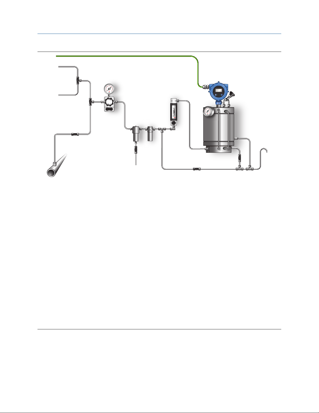
2.1 Functional view of the SGM
SGM components view
The following figures illustrate the major components of the SGM. Depending on the order, some
components may be shipped with the device or supplied by the customer.
Figure 2-1: Typical SGM installation
Configuration and Use Manual 9
STATUS
SCROLL SELECT
0
'
/
2
3
(
4
&
$79
5
0
6
*
1
)
%
$
+
,
-
Orientation and planning Configuration and Use Manual
March 2021 MMI-20020954
A. Calibration gas selector three-way valve
B. Process/Calibration gas selector three-way valve
C. Outlet two-way valve
D. Process gas inlet two-way valve
E. Chamber fill valve
F. Purge two-way valve
G. Pressure regulator with gauge
H. Calibration gas 1 inlet
I. Calibration gas 2 inlet
J. Process gas sampling point
K. Tubing work (not shown in diagram)
L. Coalescent filter
M. Coalescent filter drain two-way valve
N. Particle filter
O. Flow meter
P. Transmitter
Q. Reference chamber pressure indicator
R. Relief valve
S. Drain
ATV
Atmospheric Vent
10 Micro Motion Gas Specific Gravity Meters (SGM)
Configuration and Use Manual Orientation and planning
MMI-20020954 March 2021
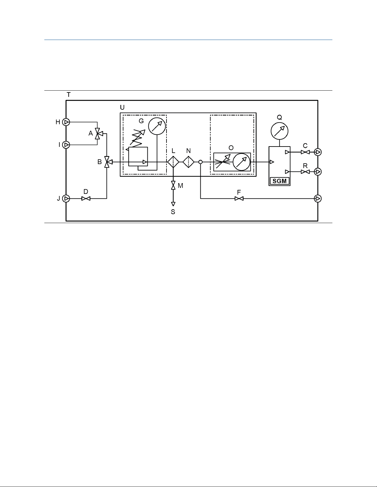
Complete sampling conditioning system
The SGM can be offered as a complete system shown in the following diagrams. The valves, filter, regulator,
and internal piping will all be included in the system with an optional electric heater.
Configuration and Use Manual 11

&$/*$6
&$/*$6
*$6
&$/*$6
STATUS
SCROLL SELECT
0
+
'
/
2
3
8
7
0
6
*
,
-
1
)
%
$
&
5
(
4
$79
Orientation and planning Configuration and Use Manual
March 2021 MMI-20020954
A. Calibration gas selector three-way valve
B. Process/Calibration gas selector three-way valve
C. Outlet two-way valve
D. Process gas inlet two-way valve
E. Chamber fill valve
F. Purge two-way valve
G. Pressure regulator with gauge
H. Calibration gas 1 inlet
I. Calibration gas 2 inlet
J. Process gas sample inlet
K. Tubing work (not shown in diagram)
L. Coalescent filter
M. Coalescent filter drain two-way valve
N. Particle filter
O. Flow meter
P. Transmitter
Q. Reference chamber pressure indicator
R. Relief valve
S. Drain
T. Enclosure
U. Mounting plate
ATV
Atmospheric Vent
12 Micro Motion Gas Specific Gravity Meters (SGM)
Configuration and Use Manual Orientation and planning
MMI-20020954 March 2021
2.2 Terms and definitions
Table 2-1: Terms used in meter setup and measurement
Term Definition or usage
Gas
Calibration gas Two or three pure, traceable calibration gases (99.9%) with a lower and higher
specific gravity/molecular weight as the process gas. Calibration gas can be the
same specific gravity as the process gas.
Reference gas The gas in the reference chamber. Typically, the process gas is used as the
reference gas.
Sample gas The gas stream to be measured by the meter.
Pressure
Control pressure The pressure of the reference gas in the reference chamber.
Line pressure The pressure in the main pipeline, independent of the meter.
Sample pressure The pressure of the sample gas after it passes through the pressure regulator.
Supply pressure The pressure of the sample gas before it passes through the pressure regulator.
Vent pressure The pressure required to force gas through the vent.
Measurement
Base density (standard density, normal
density)
Calorific value The amount of heat released during the combustion of a specified amount of a
Compressibility factor “z” The correction factor for interactive molecular behavior of non-ideal gas
Concentration (purity of binary gas
mixtures)
Energy flow The energy content of the process gas flowing through the pipe per unit of
Molecular weight The ratio of the average mass of one molecule of an element or compound to
Net mass flow rate The flow rate as measured in mass flow units and multiplied by the current
Net volume flow rate The flow rate as measured in volume flow units, corrected to base temperature
Relative density The ratio of the weight of a volume of gas (or gas mixture) to the weight of an
The absolute density of a gas at reference conditions (base temperature and
base pressure). Can be used to calculate standard volume flow from mass flow.
Measured in user-specified units.
gas. Measured in units of energy per units of the gas. Energy = calorific value.
mixtures.
In a binary gas mixture, the quantity of the primary gas in comparison to the
quantity of the secondary gas (contaminant). Measured in user-specified units.
time. Measured in units of energy per units of time.
one twelfth of the mass of an atom of carbon-12. Typically measured in g/mol.
concentration value.
and base pressure, and multiplied by the current concentration value.
equal volume of dry air, where the weights of both the gas and air are taken
under identical conditions of temperature and pressure. Unitless.
Specific gravity The ratio of the molecular weight of a gas (or gas mixture) to the molecular
weight of dry air. The molecular weight of dry air is normally assumed to be
28.96469. Unitless.
Configuration and Use Manual 13
Orientation and planning Configuration and Use Manual
March 2021 MMI-20020954
Table 2-1: Terms used in meter setup and measurement (continued)
Term Definition or usage
Wobbe index The ratio of the calorific value of a gas to its specific gravity. Measured in
volumetric units (BTU/SCF, and MJ/SCM).
2.3 Primary process variable: specific gravity, molecular weight, or relative density
The SGM can operate as a specific gravity meter, a molecular weight meter, or a relative density meter. Your
choice determines the set of process variables that the meter can report, the methods used to measure and
calculate them, and the data that you must supply during setup and configuration.
The primary process variable — specific gravity, molecular weight, or relative density — needs to be specified
as part of the order. However, you can change the primary process variable during calibration.
Related information
Primary process variable and available gas process variables
Primary process variable, gas process variables, and required data
2.3.1 Primary process variable and available gas process variables
The gas process variables that the SGM can report are determined by the primary process variable that you
select during calibration.
Available process variables
Specific gravity Unitless ✓ ✓
Molecular weight g/mol ✓ ✓
Relative density Unitless ✓
Base density g/cm³ ✓ ✓ ✓
Line density g/cm³ ✓ ✓ ✓
Line compressibility Unitless ✓ ✓ ✓
Base compressibility Unitless ✓ ✓ ✓
Calorific value MJ/m³ ✓ ✓
Wobbe index MJ/m³ ✓ ✓
Energy flow MJ/hr ✓ ✓
Concentration (gas purity) Concentration
Net mass flow rate g/sec ✓ ✓ ✓
Default
measurement unit
(% mass)
Specific gravity Molecular weight Relative density
✓ ✓ ✓
Primary process variable
Net volume flow rate l/sec ✓ ✓ ✓
14 Micro Motion Gas Specific Gravity Meters (SGM)
Configuration and Use Manual Orientation and planning
MMI-20020954 March 2021
2.3.2 Primary process variable, gas process variables, and required data
The gas process variables are calculated from a combination of measured variables, calculated variables,
process data from external devices, and user-specified values. For each process variable that you want the
meter to report, you must be able to supply all required external data and configuration values. Specific
requirements are determined by the primary process variable.
Note
The meter does not measure certain process variables directly. External devices are required for the following
process variables:
• Line pressure
• Gas composition (% CO, % CO2, % H2, % N2)
• Flow rate (mass or volume)
Note
• If you use temperature data from the meter, the data will represent the gas inside the measurement
chamber.
• If you use temperature data from an external device, the data will represent the gas at the location of the
temperature probe.
Table 2-2: Gas measurement when the primary process variable is specific gravity
Process variable to be reported Process data provided
by the SGM
Specific gravity Specific gravity
Molecular weight Specific gravity Molecular weight of air
Base density
Line density
NX 19
Line compressibility
NX 19 Mod
Molecular weight
Base compressibility
Temperature data from
meter (RTD)
Base density
Line compressibility
Base compressibility
Sample temperature
(RTD)
Specific gravity
Sample temperature
data from meter
(RTD)
Specific gravity
(1)
(1)
(1)
Required process data
from external devices
External temperature
Line pressure
External temperature
Line pressure
% CO2
% N2
External temperature
Line pressure
% CO2
% N2
Required userspecified values
Base pressure
Base temperature
(2)
Base pressure
Base temperature
(2)
Molecular weight of air
(2)
Configuration and Use Manual 15

Orientation and planning Configuration and Use Manual
March 2021 MMI-20020954
Table 2-2: Gas measurement when the primary process variable is specific gravity (continued)
Process variable to be reported Process data provided
by the SGM
Sample temperature
data from meter
(1)
NX 19 3h
(RTD)
Specific gravity
Calorific value
NX 19 Specific gravity
Base compressibility
NX 19 Mod Specific gravity
NX 19 3h
Specific gravity
Calorific value
Calorific Value AGA-5 Specific gravity
Wobbe Index
Mass units
Energy Flow
Volume units
Specific gravity
Calorific value
Line density
(3)
Calorific value
Line density
(4)
Calorific value
Required process data
from external devices
External temperature
(2)
Line pressure
% CO2
% N2
% CO2
% N2
% CO2
% N2
% CO2
% N2
% CO
% CO2
% H2
% N2
Mass flow rate (external
or calculated)
Volume flow rate
(external or calculated)
Required userspecified values
Molecular weight of air
Molecular weight of air
Base temperature
Base pressure
Base temperature
Base pressure
Molecular weight of air
Base temperature
Base pressure
(1) Used when you want process variables to represent the gas in the measurement chamber.
(2) Used when you want process variables to represent the gas at the location of the temperature probe.
(3) Required only if you plan to use the calculated mass flow measurement unit as the measurement unit for energy flow.
(4) Required only if you plan to use the calculated volume flow measurement unit as the measurement unit for energy
flow.
Table 2-3: Gas measurement when the primary process variable is molecular weight
Process variable to be reported
Process data provided
by the SGM
Molecular weight Molecular weight
Specific gravity Molecular weight Molecular weight of air
Base density
Molecular weight
Base compressibility
16 Micro Motion Gas Specific Gravity Meters (SGM)
Required process data
from external devices
Required userspecified values
Base pressure
Base temperature

Configuration and Use Manual Orientation and planning
MMI-20020954 March 2021
Table 2-3: Gas measurement when the primary process variable is molecular weight (continued)
Process variable to be reported
Line density
NX 19
NX 19 Mod
Line compressibility
NX 19 3h
SGERG-88
Process data provided
by the SGM
Sample temperature
data from meter
(1)
(RTD)
Molecular weight
Line compressibility
Sample temperature
(1)
Specific gravity
Sample temperature
data from meter
(1)
(RTD)
Sample temperature
data from meter
(1)
(RTD)
Specific gravity
Calorific value
Sample temperature
data from meter
(1)
(RTD)
Calorific value
Required process data
from external devices
External temperature
Line pressure
External temperature
Line pressure
% CO2
% N2
External temperature
Line pressure
% CO2
% N2
External temperature
Line pressure
% CO2
% N2
External temperature
Line pressure
% CO2
% H2
% N2
Required userspecified values
(2)
(2)
Molecular weight of air
(2)
(2)
Molecular weight of air
(2)
Molecular weight of air
Base temperature
Base pressure
Base temperature
Base pressure
Molecular weight of air
Base temperature
Base pressure
Base temperature
Base pressure
Base compressibility
NX 19 Specific gravity
NX 19 Mod Specific gravity
NX 19 3h
Specific gravity
Calorific value
SGERG-88 Calorific value
% CO2
% N2
% CO2
% N2
% CO2
% N2
% CO2
% H2
% N2
% CO
Calorific Value AGA-5
Line density
Specific gravity
% CO2
% H2
% N2
Wobbe Index
Specific gravity
Calorific value
Configuration and Use Manual 17

Orientation and planning Configuration and Use Manual
March 2021 MMI-20020954
Table 2-3: Gas measurement when the primary process variable is molecular weight (continued)
Process variable to be reported
Mass units
Energy Flow
Volume units Calorific value
(1) Used when you want process variables to represent the gas in the measurement chamber.
(2) Used when you want process variables to represent the gas at the location of the temperature probe.
Process data provided
by the SGM
Line density
Calorific value
Required process data
from external devices
Mass flow rate (direct
input or calculated)
Volume flow rate
(direct input or
calculated)
Required userspecified values
Table 2-4: Gas measurement when the primary process variable is relative density
Process variable to be reported
Relative density Relative density
Base density Relative density Base density of air
Line density
Line compressibility
Process data provided
by the SGM
Temperature data from
meter (RTD)
Base density
Line compressibility
Base compressibility
Temperature data from
meter (RTD)
Relative density
(1)
(1)
Required process data
from external devices
External temperature
Line pressure
External temperature
Line pressure
% CO2
% H2
% N2
Required userspecified values
(2)
Base temperature
Base pressure
(2)
% CO2
Base compressibility Relative density
(1) Used when you want process variables to represent the gas in the measurement chamber.
(2) Used when you want process variables to represent the gas at the location of the temperature probe.
% H2
% N2
Base temperature
Base pressure
2.4 Equations used to calculate specific gravity,
molecular weight, and relative density
2.4.1 Primary process variable = specific gravity
The following equations are used when the primary process variable is specific gravity.
Specific gravity
SG = K0 + K1 × τ + K2 × τ
SG
18 Micro Motion Gas Specific Gravity Meters (SGM)
Specific gravity of process gas
2

Configuration and Use Manual Orientation and planning
MMI-20020954 March 2021
K0, K1, K2
Calibration factors from the on-site calibration. If a two-point calibration was performed, K1 is
set to 0.
τ
Sensor time period (microseconds)
Molecular weight calculated from specific gravity
MW
SG
MW
Gas
Air
MW
Molecular weight of process gas (g/mol)
Specific gravity of process gas
Molecular weight of air (user-specified; default = 28.96469 g/mol)
Gas
= SG
Gas
× MW
Air
2.4.2 Primary process variable = molecular weight
The following equations are used when the primary process variable is molecular weight.
Molecular weight
2
MW
K0, K1, K2
MW = K0 + K1 × τ + K2 × τ
Molecular weight of process gas
Calibration factors from the on-site calibration. If a two-point calibration was performed, K1 is
set to 0.
τ
Sensor time period (microseconds)
Specific gravity calculated from molecular weight
MW
MW
Gas
Air
SG
MW
MW
Gas
Air
SG =
Specific gravity of process gas
Molecular weight of process gas (g/mol)
Molecular weight of air (user-specified; default = 28.96469 g/mol)
2.4.3 Primary process variable = relative density
The following equation is used when the primary process variable is relative density.
Relative density
2
RD
K0, K1, K2
τ
RD = K0 + K1 × τ + K2 × τ
Relative density of process gas
Calibration factors from the on-site calibration. If a two-point calibration was performed, K1 is
set to 0.
Sensor time period (microseconds)
Configuration and Use Manual 19

Orientation and planning Configuration and Use Manual
March 2021 MMI-20020954
20 Micro Motion Gas Specific Gravity Meters (SGM)

Configuration and Use Manual Quick start
MMI-20020954 March 2021
3 Quick start
3.1 Power up the transmitter
The transmitter must be powered up for all configuration and commissioning tasks, or for process
measurement.
Procedure
1. Ensure that all transmitter and sensor covers and seals are closed.
WARNING
To prevent ignition of flammable or combustible atmospheres, ensure that all covers and seals are
tightly closed. For hazardous area installations, applying power while housing covers are removed or
loose can cause an explosion.
2. Turn on the electrical power at the power supply.
The transmitter will automatically perform diagnostic routines. During this period, Alert 009 is active.
The diagnostic routines should complete in approximately 30 seconds.
Postrequisites
Although the sensor is ready to receive process fluid shortly after power-up, the electronics can take up to
10 minutes to reach thermal equilibrium. Therefore, if this is the initial startup, or if power has been off long
enough to allow components to reach ambient temperature, allow the electronics to warm up for
approximately 10 minutes before relying on process measurements. During this warm-up period, you may
observe minor measurement instability or inaccuracy.
3.2 Check meter status
Check the meter for any error conditions that require user action or that affect measurement accuracy.
Procedure
1. Wait approximately 10 seconds for the power-up sequence to complete.
Immediately after power-up, the transmitter runs through diagnostic routines and checks for error
conditions. During the power-up sequence, Alert A009 is active. This alert should clear automatically
when the power-up sequence is complete.
2. Check the status LED on the transmitter.
Table 3-1: Transmitter status reported by status LED
LED state Description Recommendation
Green No alerts are active. Continue with configuration or process
measurement.
Yellow One or more low-severity alerts are active. A low-severity alert condition does not affect
measurement accuracy or output behavior.
You can continue with configuration or
process measurement. If you choose, you can
identify and resolve the alert condition.
Configuration and Use Manual 21

Quick start Configuration and Use Manual
March 2021 MMI-20020954
Table 3-1: Transmitter status reported by status LED (continued)
LED state Description Recommendation
Flashing yellow Calibration in progress, or Known Density
Verification in progress.
Red One or more high-severity alerts are active. A high-severity alert condition affects
The measurement can fluctuate during the
calibration process or change as a result of the
calibration process. The alert will clear when
the calibration is complete. Check the
calibration results before continuing.
measurement accuracy and output behavior.
Resolve the alert condition before continuing.
Related information
View and acknowledge status alerts
Status alerts, causes, and recommendations
3.3 Make a startup connection to the transmitter
For all configuration tools except the display, you must have an active connection to the transmitter to
configure the transmitter.
Procedure
Identify the connection type to use, and follow the instructions for that connection type in the appropriate
appendix. Use the default communications parameters shown in the appendix.
Communications tool
Connection type to use Instructions
ProLink III Modbus/RS-485
HART/Bell 202
Field communicator HART/Bell 202 Using the field communicator with the
Using ProLink III with the transmitter
transmitter
Postrequisites
(Optional) Change the communications parameters to site-specific values.
ProLink III
Field communicator Configure → Manual Setup → HART → Communications
Device Tools → Configuration → Communications
Important
If you are changing communications parameters for the connection type that you are using, you will lose the
connection when you write the parameters to the transmitter. Reconnect using the new parameters.
22 Micro Motion Gas Specific Gravity Meters (SGM)

Configuration and Use Manual Introduction to configuration and commissioning
MMI-20020954 March 2021
4 Introduction to configuration and commissioning
4.1 Default values
Default values for your SGM meter are configured at the factory.
Important
Default values are based on your purchase order options. Therefore, the default values described in the
following tables may not be the factory default values configured for your system. For absolute accuracy,
refer to the configuration sheet that was shipped with your meter.
4.1.1 SGM default mA scaling values
Table 4-1: Primary variables
Variable Default 4 mA Default 20 mA
Specific gravity for calibration range 1 0 0.4
Specific gravity for calibration range 2 0 0.4
Specific gravity for calibration range 3 0 0.4
Specific gravity for calibration range 4 0 0.4
Molecular weight for calibration range10 g/mol 28.96469 g/mol
Molecular weight for calibration range20 g/mol 28.96469 g/mol
Molecular weight for calibration range30 g/mol 28.96469 g/mol
Molecular weight for calibration range40 g/mol 28.96469 g/mol
Sensor time period 400 us 1200 us
Table 4-2: Derived variables
Variable Default 4 mA Default 20 mA
Base density 0.000 g/cm3 0.400 g/cm3
Calorific value 20 MJ/Nm3 60 MJ/Nm3
Wobbe index 20 MJ/Nm3 60 MJ/Nm3
Sample temperature -50.000°C
-58°F
Drive gain 0.000 % 100.000 %
External temperature -50.000°C
-58.00000°F
Configuration and Use Manual 23
200.000°C
392°F
200.000°C
392.0000°F

Introduction to configuration and commissioning Configuration and Use Manual
March 2021 MMI-20020954
Table 4-2: Derived variables (continued)
Variable Default 4 mA Default 20 mA
External pressure 0.000 PSIg 1450.377 PSIg
Line density 0 g/cm3 0.4 g/cm3
User-defined calculation output 0 100
%CO
%N
%H
2
2
2
0 % 100.00 %
0 % 100.00 %
0 % 100.00 %
%CO 0 % 100.00 %
Table 4-3: Concentration measurement enabled
Variable Default 4 mA Default 20 mA
Gas purity concentration for curve 1 00.00 % 100.00 %
Gas purity concentration for curve 2 00.00 % 100.00 %
Gas purity concentration for curve 3 00.00 % 100.00 %
Gas purity concentration for curve 4 00.00 % 100.000 %
Table 4-4: Flow input enabled
Variable Default 4 mA Default 20 mA
Mass flow rate (calculated) -200.00 g/sec 200.00 g/sec
Mass flow rate (external) -200.00 g/sec 200.00 g/sec
Volume flow rate (calculated) -0.42378 SCFM 0.42378 SCFM
Volume flow rate (external) -0.2 l/sec 0.2 l/sec
Table 4-5: SGM default variables
Default variable Output option A Output options B and C
Primary Variable (PV), mA1 Sample Temperature • Specific Gravity for Calibration Set 1
• Molecular Weight for Calibration Set 1
• Relative Density
Secondary Variable (SV), mA2 Time Period B Sample Temperature
Tertiary Variable (TV) • Specific Gravity for
Calibration Set 1
• Molecular Weight for
Calibration Set 1
• Relative Density
Quaternary Variable (QV) Drive Gain Drive Gain
24 Micro Motion Gas Specific Gravity Meters (SGM)
Sensor Time Period
&%
'
(
$
Configuration and Use Manual Introduction to configuration and commissioning
MMI-20020954 March 2021
4.2 Enable access to the off-line menu of the display
ProLink III Device Tools → Configuration → Transmitter Display → Display Security
Field communicator Configure → Manual Setup → Display → Display Menus → Offline Menu
By default, access to the off-line menu of the display is enabled. If it is disabled, you must enable it if you want
to use the display to configure the transmitter.
Restriction
You cannot use the display to enable access to the off-line menu. You must make a connection from another
tool.
4.3 Disable HART security
If you plan to use HART protocol to configure the device, HART security must be disabled. HART security is
disabled by default, so you may not need to do this.
Prerequisites
• Strap wrench
• 3 mm hex key
Procedure
1. Power down the meter.
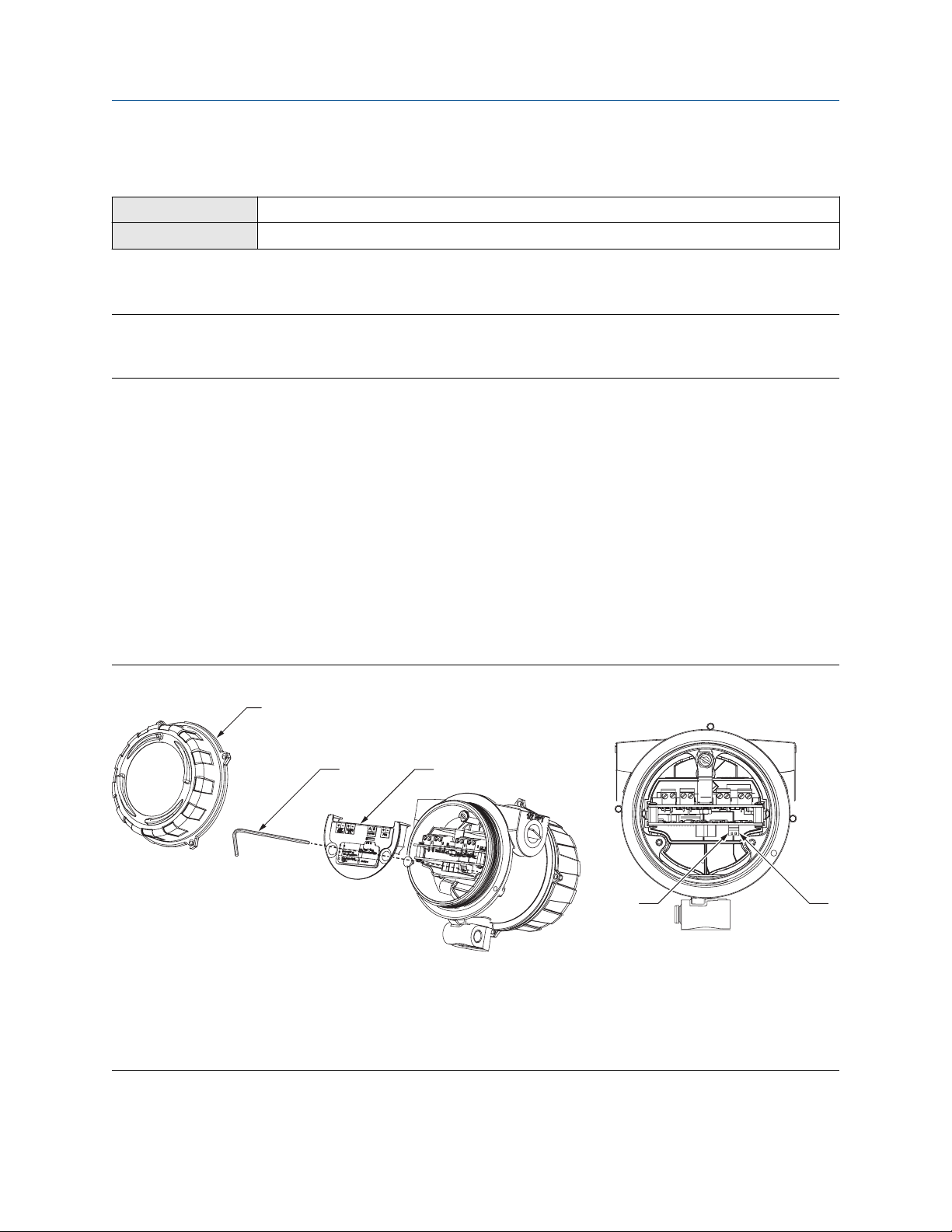
2. Using the strap wrench, loosen the grub screws and remove the transmitter end-cap.
Figure 4-1: Transmitter with end-cap removed
A. Transmitter end-cap
B. 3 mm hex key
C. Safety spacer
D. HART security switch
E. Unused
3. Using the hex key, remove the safety spacer.
Configuration and Use Manual 25

Introduction to configuration and commissioning Configuration and Use Manual
March 2021 MMI-20020954
4. Move the HART security switch to the OFF position (up).
The HART security switch is the switch on the left.
5. Replace the safety spacer and end-cap.
6. Power up the meter.
4.4 Set the HART lock
If you plan to use a HART connection to configure the device, you can lock out all other HART masters. If you
do this, other HART masters will be able to read data from the device but will not be able to write data to the
device.
Restriction
HART lock is only available:
• When you are using a field communicator or AMS
• With a HART 7 host
Procedure
1. Choose Configure → Manual Setup → Security → Lock/Unlock Device.
2. If you are locking the meter, set Lock Option as desired.
Option
Permanent Only the current HART master can make changes to the device. The device will remain
Temporary Only the current HART master can make changes to the device. The device will remain
Lock All No HART masters are allowed to make changes to the configuration. Before changing
Postrequisites
To avoid future confusion or difficulties, ensure that the device is unlocked after you have completed your
tasks.
Description
locked until manually unlocked by a HART master. The HART master can also change
Lock Option to Temporary.
locked until manually unlocked by a HART master, or a power-cycle or device reset is
performed. The HART master can also change Lock Option to Permanent.
Lock Option to Permanent or Temporary, the device must be unlocked. Any HART
master can be used to unlock the device.
4.5 Restore the factory configuration
The SGM is a field-configured device. Therefore, attempts to restore the factory configuration will result in an
error since no factory configuration is loaded into the SGM electronics.
26 Micro Motion Gas Specific Gravity Meters (SGM)

Configuration and Use Manual Purging and calibration
MMI-20020954 March 2021
5 Purging and calibration
5.1 On-site setup requirements
The SGM is shipped with an empty reference chamber and no calibration factors. The SGM cannot be factory
calibrated. Instead, you must perform calibration in the field using one of two on-site setup procedures. A
setup procedure involves purging and filling the reference chamber with your process gas, then using known
calibration gases.
Related information
Prepare for SGM purging and calibration
Purge and purge-cycle the SGM device
Calibrate the SGM device
Review data for all calibrations
Select the active calibration
5.2 Prepare for SGM purging and calibration
Before you begin these procedures, you must:
• Know the primary process variable that you want to use. In other words, you must know whether the
meter will operate as a specific gravity meter, a molecular weight meter, or a relative density meter.
• Know if you need a two-point or three-point calibration. Most applications require a two-point calibration.
For a few exceptions, a three-point calibration may be required.
• Prepare the calibration gases.
• Know the appropriate control pressure.
• Be able to control sample pressure and vent pressure.
Related information
Three-point calibration
5.2.1 Primary process variable: specific gravity, molecular weight,
or relative density
The SGM can operate as a specific gravity meter, a molecular weight meter, or a relative density meter. Your
choice determines the set of process variables that the meter can report, the methods used to measure and
calculate them, and the data that you must supply during setup and configuration.
The primary process variable — specific gravity, molecular weight, or relative density — needs to be specified
as part of the order. However, you can change the primary process variable during calibration.
Related information
Primary process variable and available gas process variables
Primary process variable, gas process variables, and required data
Configuration and Use Manual 27

Purging and calibration Configuration and Use Manual
March 2021 MMI-20020954
5.2.2 Two-point calibration vs. three-point calibration
Your choice of two-point calibration or three-point calibration depends on how many process gases you are
using.
Two-point
calibration
Three-point
calibration
Related information
Three-point calibration
Two gases are used for calibration. Standard and most common applications require
only two calibration points to get the best accuracy. A two-point calibration produces
two calibration factors: K0 and K2. K1 is set to 0.
Three gases are used for calibration. Three-point calibrations are less common. For
more information, see Three-point calibration.
5.2.3 Calibration gases
The calibration gases should match the main constituents of your process gas. The gases must cover the
lower and upper SG/MW range of the process gas and have similar compressibility characteristics.
Gas types and requirements
Analytical calibration gases are specified by purity grade or number of 9’s. “High purity” or “4.5 nines
(99.995%)” grades are good choices for calibrating the SGM.
For example, if the SGM is measuring the specific gravity of natural gas, use pure nitrogen and pure methane
as calibration gases.
Table 5-1: Examples of calibration gases
Application Two-point calibration gases
Natural gas Methane and nitrogen
Hydrogen purity Hydrogen and nitrogen
Fuel to air ratio Methane and propane
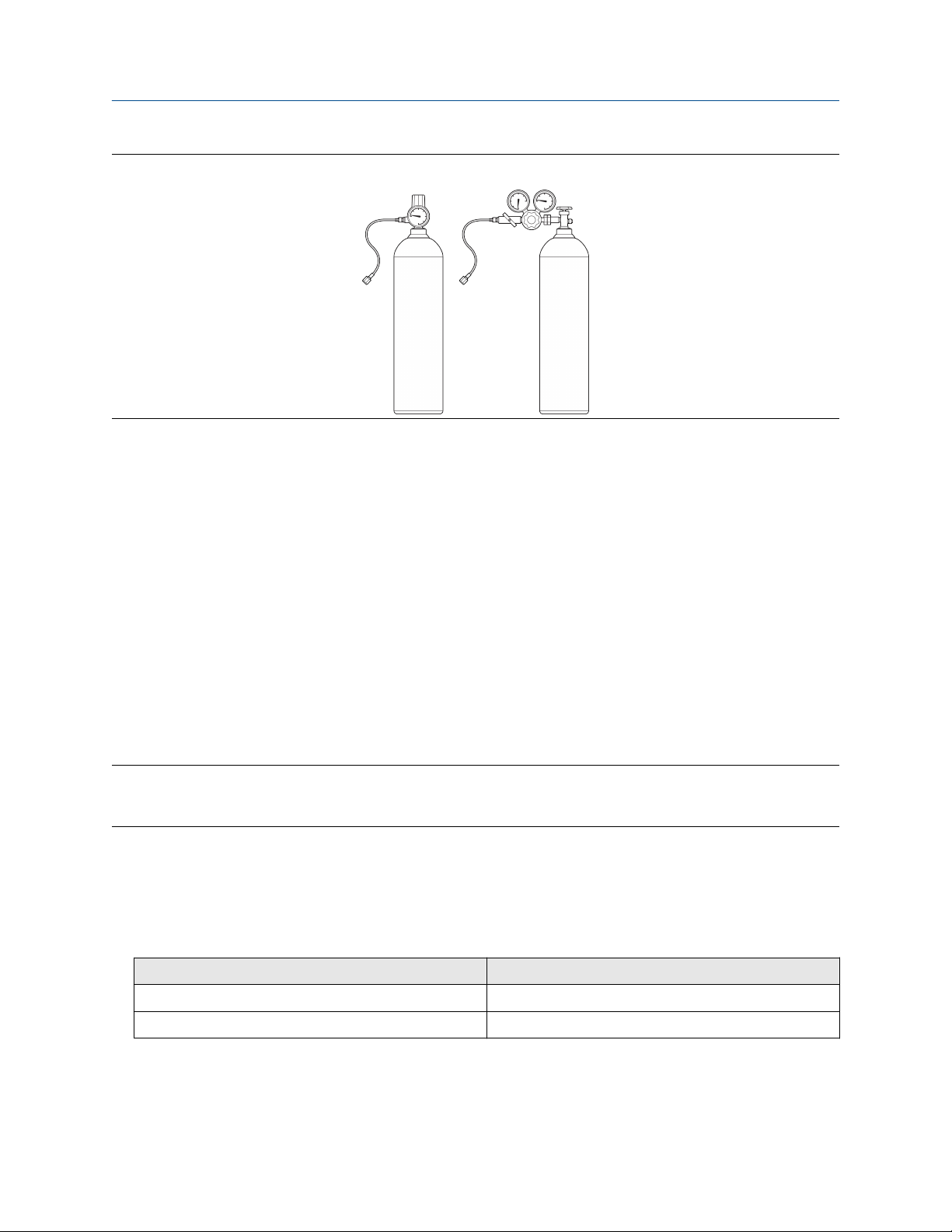
Equipment requirements
• Cylinders must have a gauge regulator and hose.
• The hose needs to have a 0.25 in (6.4 mm) Swagelok® female connector.
• The minimum gas bottle size for each of the calibration gases should be no less than 4.5 gallons (17 liters)
at a 20% higher of nominal pressure at the outlet of the regulator depending on the application.
Most gas suppliers can provide these items.
28 Micro Motion Gas Specific Gravity Meters (SGM)
Configuration and Use Manual Purging and calibration
MMI-20020954 March 2021
Figure 5-1: Examples of cylinders with pressure regulators, hoses, and compression fittings
Data entry for gas calibration
During calibration, you will be required to enter data for each calibration gas:
• If the SGM is operating as a specific gravity meter, you must enter the specific gravity of the gas.
During calibration, you must be able to flow each calibration gas through the meter in the order of their
specific gravity, lowest to highest.
• If the SGM is operating as a relative density meter, you must enter the relative density of the calibration
gas.
• If the SGM is operating as a molecular weight meter, you must enter the molecular weight of the gas.
5.2.4 Pressure
A meter with the sampling conditioning system includes a pressure regulator with indicator that:
• Controls the inlet sample pressure
• Allows you to verify sample pressure
Note
All SGM models come with an included pressure gauge that identifies only the reference chamber pressure
that is used for pressure and compressibility compensation.
For SGM models without the sampling conditioning system, a pressure regulator with indicator must be
installed by the customer.
The pressure in the system must meet the following requirements:
• The maximum sample inlet pressure (the pressure regulator with gauge in Pressure) for the different SGM
models should not exceed:
SGM model
SGM2, SGM3 (without pressure regulator) 122 psia (8.41 bara)
Pressure rating
SGM4 (with pressure regulator) 1,450 psia (100 bara)
• Reference chamber maximum pressure: 101 psia (6.96 bara)
Configuration and Use Manual 29

Purging and calibration Configuration and Use Manual
March 2021 MMI-20020954
Determine the reference chamber pressure
The reference chamber pressure must be appropriate to your application. You must know the desired
reference chamber pressure before you begin the purge and calibration process. The reference chamber
pressure also affects the inlet sample supply pressure and the outlet vent pressure that you must maintain in
the system.
Guidelines for reference chamber pressure
Use the following guidelines for reference chamber pressure:
• Between 17 psia (1.17 bara) and 101 psia (7 bara), at 68 °F (20 °C)
• Less than the inlet sample pressure by 15% to 25%
• Greater than the outlet vent pressure
These pressure settings work for most applications. Use them as starting point, or use them to calculate
reference chamber pressure using data that is specific to your process.
Related information
Calculate measurement errors using reference chamber pressure
5.2.5 Multiple calibrations
The SGM can store calibrations for up to four different process gases or ranges. Each calibration is generated
by an independent calibration procedure and contains an independent set of calibration coefficients. This
feature allows you to switch between process gases or ranges without recalibrating the device.
If you plan to use more than one calibration:
• Perform all calibrations using the same measurement option: specific gravity, molecular weight, or
relative density.
• Set calibrations as either two-point calibrations or three-point calibrations.
• Complete each calibration before beginning the next calibration.
• Choose to add calibrations at a later time. You do not need to perform all calibrations at the same time.
Important
It is possible to use a different reference chamber pressure for each calibration. If you do, change the
reference chamber pressure in the meter whenever you change the active calibration. If you do not change
the reference chamber pressure to match the active calibration, measurement accuracy will be affected.
Calibration ranges
• If you have a specific gravity meter, the meter will automatically calculate the specific gravity output
variable for all four ranges during operation.
• If you have a molecular weight meter, the meter will automatically calculate the molecular weight output
variable for all four ranges during operation.
• If you have a relative density meter, only one calibration is applied at a time. A control selects the active
calibration.
• For specific gravity and molecular weight meters — energy, energy flow, compressibility, and Wobbe index
are calculated only from the active calibration. Gas purity is automatically calculated for the associated
30 Micro Motion Gas Specific Gravity Meters (SGM)

Configuration and Use Manual Purging and calibration
MMI-20020954 March 2021
calibration (for example, Gas Purity Concentration for curve 4 automatically uses calibration range 4).
Damping is applied only to the active variable.
5.3 Purge and purge-cycle the SGM device
Purging the SGM device prepares it for calibration by ensuring that the reference chamber is filled and sealed
with appropriate process gas to the desired pressure.
Prerequisites
• You must be able to flow process gas through the device.
• You must know the working pressure of your system and the desired reference chamber pressure.
Configuration and Use Manual 31
0
STATUS
SCROLL SELECT
'
/
2
3
&
5
0
6
*
1
%
$
+
,
-
(
4
8
9
:
7
7
$79
)
Purging and calibration Configuration and Use Manual
March 2021 MMI-20020954
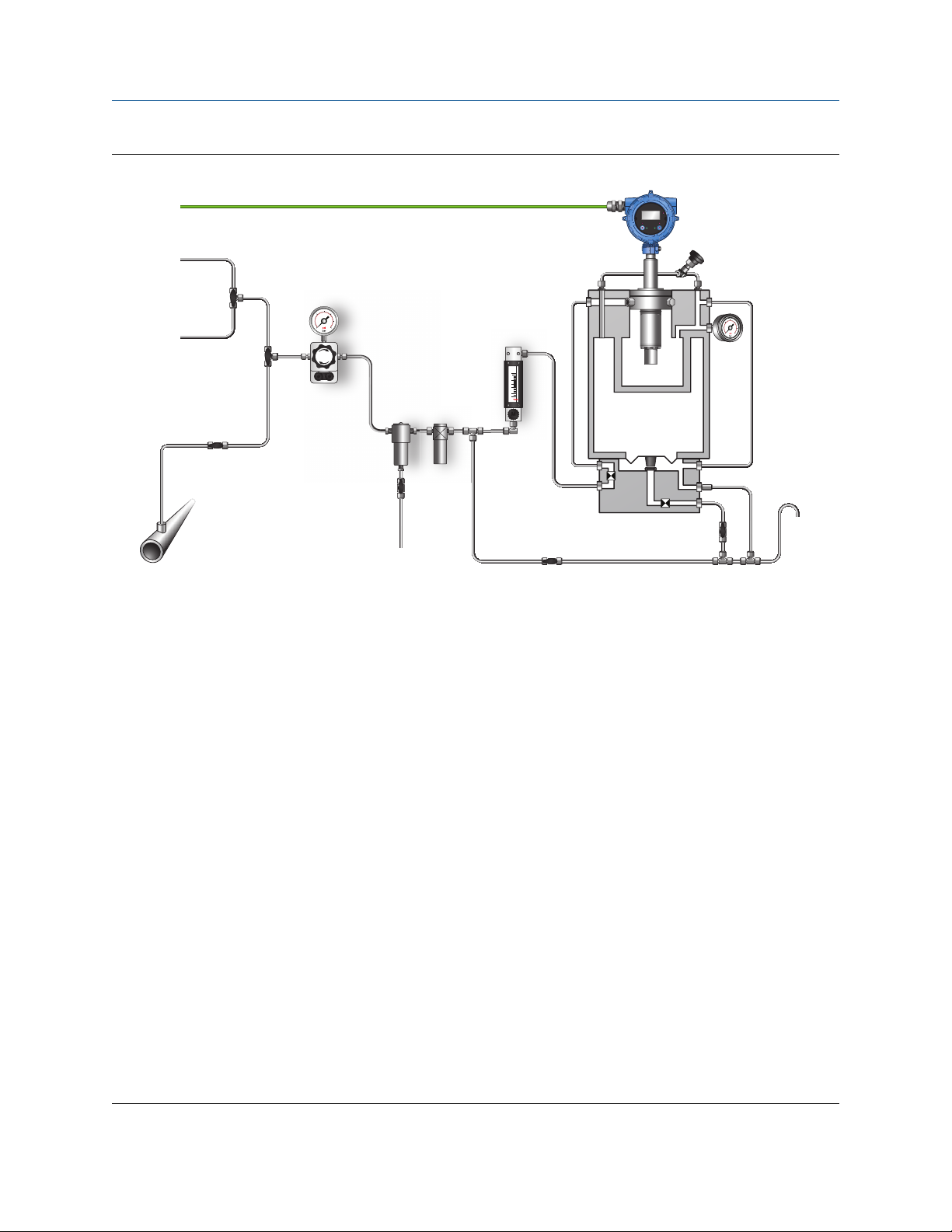
Figure 5-2: Pictorial representation of a typical SGM installation
A. Calibration gas selector three-way valve
B. Process/Calibration gas selector three-way valve
C. Outlet two-way valve
D. Process gas inlet two-way valve
E. Chamber fill valve
F. Purge two-way valve
G. Pressure regulator with gauge
H. Calibration gas 1 inlet
I. Calibration gas 2 inlet
J. Process gas sampling point
K. Tubing work (not shown in diagram)
L. Coalescent filter
M. Coalescent filter drain two-way valve
N. Particle filter
O. Flow meter
P. Transmitter
Q. Reference chamber pressure indicator
R. Relief valve
S. Drain
T. Internal orifice restriction
U. Measurement chamber
V. Reference chamber
W. Diaphragm
ATV
Atmospheric Vent
32 Micro Motion Gas Specific Gravity Meters (SGM)

Configuration and Use Manual Purging and calibration
MMI-20020954 March 2021
Procedure
1. Close the process gas inlet two-way valve (D), outlet valve (C), purge valve (F), and drain valves (M).
2. Set the process/calibration selector valve (B) to the Process Gas position.
3. Open the process gas inlet two-way valve (D).
4. Open the outlet valve (C).
5. Set the pressure regulator (G) to the working pressure of the system without exceeding 122 psia
(8.41 bara).
6. Open the chamber filling valve (E).
7. Allow gas to flow for three minutes.
8. Close the outlet valve (C).
9. Observe the reference chamber pressure gauge (Q) until it reaches the desired pressure:
a) Close the process gas inlet two-way valve (D) and open the purge valve (F), allowing the gas to
vent to atmospheric pressure.
10. Purge-cycle the device.
a) Close the purge valve (F) and open the process gas inlet two-way valve (D).
b) Observe the reference chamber pressure indicator (Q) until it reaches the desired control
pressure, close the process gas inlet two-way valve (D) and open the purge valve (F).
c) Allow the gas to vent to atmospheric pressure.
d) Repeat this step for the required number of cycles, as determined by the following equation:
NumberPurgeCycles=
11. Close the purge valve (F) and open the process gas inlet two-way valve (D).
12. When the reference chamber pressure reaches the desired value, close the chamber filling valve (E) and
the process gas inlet valve (D) in preparation for flowing the calibration gases.
The reference chamber is now filled with the reference gas at the control pressure, and the SGM is ready to
run the calibration gases.
Important
After the reference chamber has been filled, do not open the chamber filling valve (N) again.
Related information
Functional view of the SGM
MaxRegulatorPressure
21
5.4 Calibrate the SGM device
The SGM device must be calibrated for your process gas. The SGM leaves the factory uncalibrated and
requires proper field calibration to generate calibration coefficients for your process gas.
Prerequisites
• You must have completed the purge procedure, and the reference chamber must be filled with the
reference gas to the appropriate pressure.
Configuration and Use Manual 33

Purging and calibration Configuration and Use Manual
March 2021 MMI-20020954
• You must know whether you want the device to operate as a specific gravity meter, a molecular weight
meter, or a relative density meter.
• You must know if you want a two-point calibration or a three-point calibration. Most applications require a
two-point calibration. In purity applications, a three-point calibration may be more appropriate. For more
information, see Three-point calibration.
• You must have identified all required calibration gases and know their specific gravity, molecular weight,
or relative density.
• You must be prepared to flow all calibration gases through the device, at the appropriate sample pressure.
In a typical application, the sample pressure should be approximately 20% greater than the reference
chamber pressure.
Related information
Calibrate the SGM device using the display
Calibrate the SGM device using ProLink III
Calibrate the SGM device using a field communicator
5.4.1 Calibrate the SGM device using the display
Procedure
1. Read the Prerequisites in Calibrate the SGM device if you have not already done so.
2. Enter the Off-Line Maintenance menu and activate SCROLL until OFF-LINE CAL appears on the display,
then activate Select.
3. When CAL SG appears, activate Select.
4. Set the measurement type for this device.
a) When CAL TYPE appears, activate Select, then scroll through the list of options.
b) When the desired option appears, activate Select, then store the selection.
Option
Specific Gravity Meter Gas density will be measured as specific gravity, and specific gravity will be
Molecular Weight Meter Gas density will be measured as molecular weight, and molecular weight
Relative Density Meter Gas density will be measured as relative density, and relative density will be
5. Set the calibration type (calibration format).
a) Activate SCROLL until CAL PTS appears.
Description
used for calibration.
will be used for calibration.
used for calibration.
b) Activate Select, then scroll through the list of options.
c) When the desired option appears, activate Select, then store the selection.
34 Micro Motion Gas Specific Gravity Meters (SGM)

Configuration and Use Manual Purging and calibration
MMI-20020954 March 2021
Option Description
2-Point Calibration Appropriate for gases with two main constituents. Requires two calibration
gases.
3-Point Calibration Appropriate for gases with three main constituents. Use only if recommended by
customer support. For more information, see Three-point calibration.
6. Select the number of the calibration that you want to perform.
a) When CAL NUMBR appears, activate Select, then scroll through the list of options.
b) When the desired option appears, activate Select, then store the selection.
The device can store up to four independent calibration ranges. All calibrations must have the same
calibration type (2-point or 3-point). Each calibration can use different calibration gases.
7. Set the low-density calibration point. See Figure 5-2.
a) Connect the lower calibration gas to the calibration gas inlet 1 (H).
b) Set the pressure regulator on the lower calibration gas tank to the appropriate sample pressure
for your installation.
Note
Make sure the process gas inlet valve (D) is closed.
c) Set the gas selector valve (A) to the calibration gas inlet 1 position and open the outlet valve (C).
d) Set the process/calibration selector valve (B) to the calibration position.
e) Activate SCROLL until ENTER GAS LOW appears, then activate SELECT.
f) Enter the specific gravity, molecular weight, or relative density of the calibration gas that is
flowing through the system and store the value by activating both SCROLL and SELECT at same
time until the previous menu appears.
g) Activate SCROLL.
h) When CAL GAS LOW appears, activate Select to start the calibration.
i) During the calibration, activate SCROLL to observe the Sensor Time Period and Stability values
during the calibration.
j) Wait between 3 to 15 minutes for the system to stabilize. When Stability is Good, activate
Select.
If measurement does not stabilize after 30 minutes, activate SCROLL to abort the calibration.
k) Activate Select again to accept the calibration value.
l) As the gas flows, select the Start button and observe the Sensor Time Period and Stability
values.
8. Set the high-density calibration point.
a) Connect the higher calibration gas to the calibration gas 2 inlet (I).
b) Set the pressure regulator on the higher calibration gas to the appropriate sample pressure for
your installation.
Configuration and Use Manual 35

Purging and calibration Configuration and Use Manual
March 2021 MMI-20020954
c) Set the calibration gas selector valve (A) to the calibration gas 2 inlet (I) position. The process
gas inlet valve (D) must remain closed.
d) Activate SCROLL until ENTER GAS HIGH appears, then activate Select.
e) Enter the specific gravity, molecular weight, or relative density of the calibration gas that is
flowing through the system and store the value by activating both SCROLL and SELECT at same
time until the previous menu appears.
f) Activate SCROLL
g) When CAL GAS HIGH appears, activate Select to start the calibration.
h) During the calibration, activate SCROLL to observe the Sensor Time Period and Stability values
during the calibration.
i) Wait between 3 to 15 minutes for the system to stabilize. When Stability is Good, activate
Select.
If measurement does not stabilize after 30 minutes, activate SCROLL to abort the calibration.
j) Activate Select again to accept the calibration value.
k) As the gas flows, select the Start button and observe the Sensor Time Period and Stability
values.
l) Disconnect the lower calibration gas.
9. Activate SCROLL until CALC K VAL appears, then activate Select.
The meter automatically calculates the calibration factors from the stored data.
10. View the calibration factors.
a) When RESULT DISPLAY appears, activate Select.
b) Activate SCROLL to view the calibration factors and data.
Results are displayed in this order:
• The specific gravity, molecular weight, or relative density used to calculate the K0 calibration
factor
• The time period used to calculate the K0 calibration factor
• The specific gravity, molecular weight, or relative density used to calculate the K1 calibration
factor (3-point calibrations only)
• The time period used to calculate the K1 calibration factor (3-point calibrations only)
• The specific gravity, molecular weight, or relative density used to calculate the K2 calibration
factor
• The time period used to calculate the K2 calibration factor
• The K0 calibration factor
• The K1 calibration factor (3-point calibrations only), displayed in exponential format
• The K2 calibration factor, displayed in exponential format
36 Micro Motion Gas Specific Gravity Meters (SGM)
Configuration and Use Manual Purging and calibration
MMI-20020954 March 2021
c) When Exit appears, activate Select.
11. Select the calibration to be used for measurement.
a) Activate SCROLL until CAL ACTIVE appears.
b) Activate Select, then scroll through the list of options.
c) When the desired option appears, activate Select, then store the selection.
12. Optional: To add a calibration, return to the first step and repeat this procedure.
13. The SGM is ready to be used. Shut off the calibration gas regulators and set the process/calibration
selector valve (B) to the process gas position and open the process gas inlet valve (D) to let process gas
flow through the system and be measured.
Related information
Functional view of the SGM
Verify the SGM calibration
5.4.2 Calibrate the SGM device using ProLink III
Procedure
1. Read the Prerequisites in Calibrate the SGM device if you have not already done so.
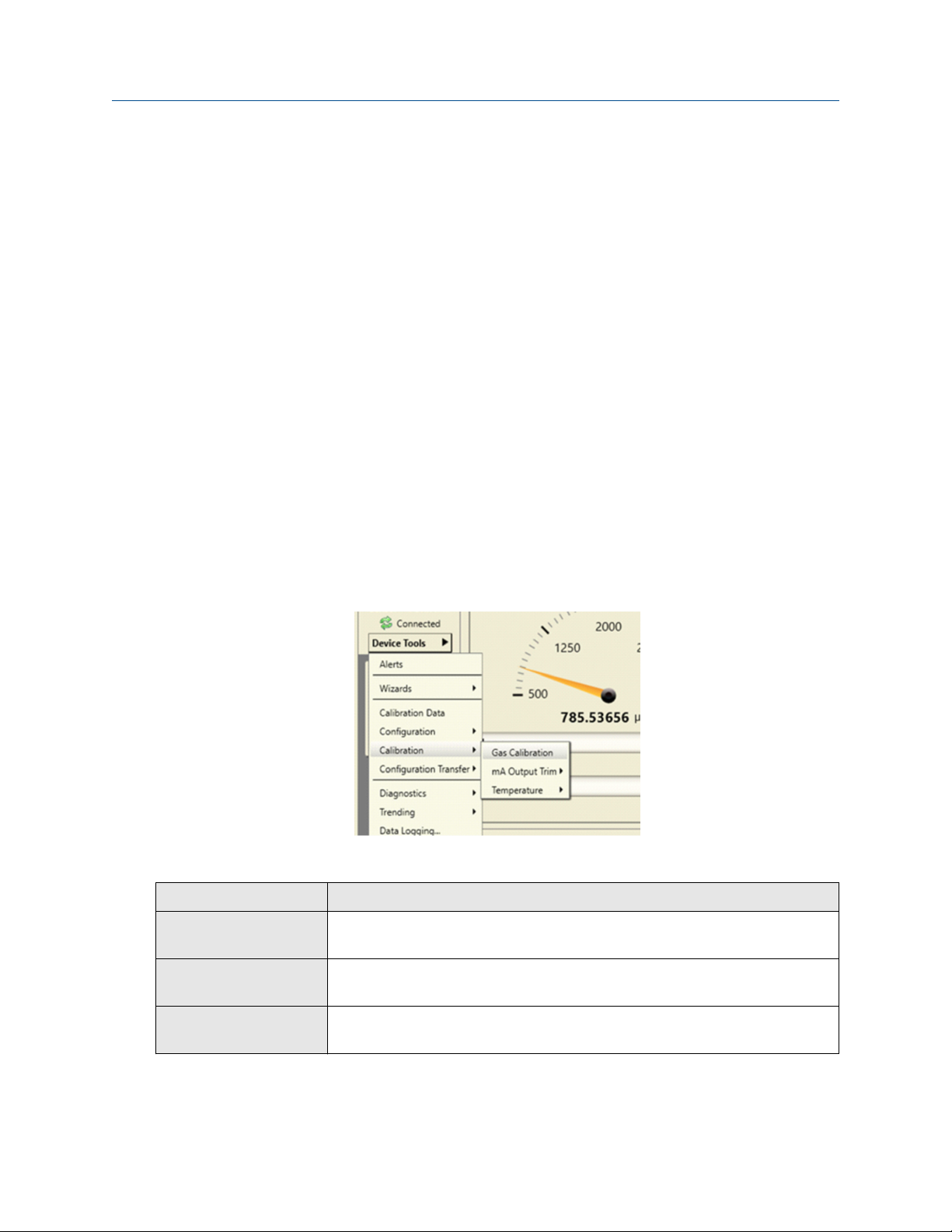
2. Choose Device Tools → Calibration → Gas Calibration.
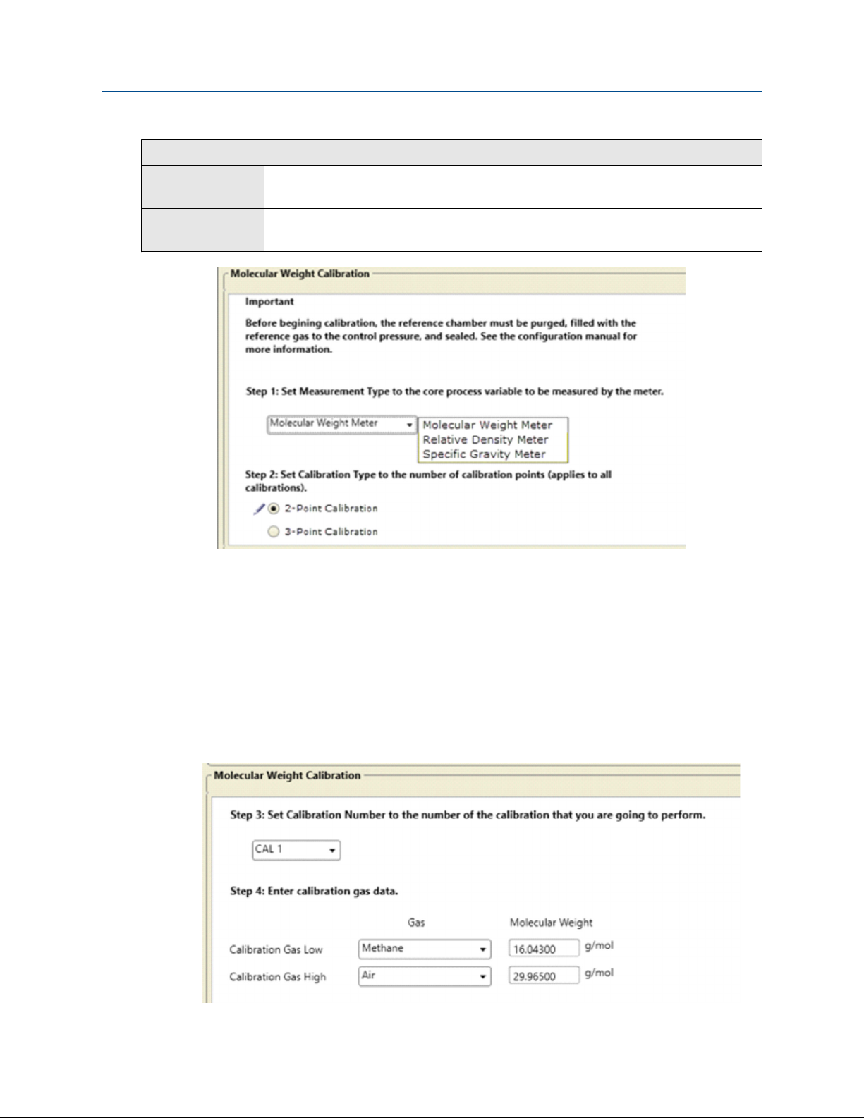
3. Set the measurement type for this device.
Option
Specific Gravity Meter Gas density will be measured as specific gravity, and specific gravity will be
Molecular Weight Meter Gas density will be measured as molecular weight, and molecular weight
Description
used for calibration.
will be used for calibration.
Relative Density Meter Gas density will be measured as relative density, and relative density will be
used for calibration.
4. Set the calibration type (calibration format).
Configuration and Use Manual 37
Purging and calibration Configuration and Use Manual
March 2021 MMI-20020954
Option Description
2-Point Calibration Appropriate for gases with two main constituents. Requires two calibration
gases.
3-Point Calibration Appropriate for gases with three main constituents. Use only if recommended by
customer support. For more information, see Three-point calibration.
5. Select Next.
6. Select the number of the calibration that you want to perform (CAL 1, CAL 2, CAL 3, or CAL 4).
The device can store up to four independent calibration ranges. All calibrations must have the same
calibration type (2-point or 3-point). Each calibration can use different calibration gases.
7. Enter data for each calibration gas.
a) Select the calibration gas from the list for Calibration Gas Low and Calibration Gas High. If it is
not listed, select Other.
b) Enter the specific gravity, molecular weight, or relative density of the calibration gas for
Calibration Gas Low and Calibration Gas High.
38 Micro Motion Gas Specific Gravity Meters (SGM)
Configuration and Use Manual Purging and calibration
MMI-20020954 March 2021
c) Select Next.
Tip
Enter the calibration gases in order of density, from lowest to highest. This allows heavier gases to
replace lighter gases.
8. Set the low-density calibration point. See Figure 5-2.
a) Connect the lower calibration gas to the calibration gas inlet 1 (H).
b) Set the pressure regulator on the lower calibration gas tank to the appropriate sample pressure
for your installation.
Note
Make sure the process gas inlet valve (D) is closed.
c) Set the process/calibration gas valve (B) to the calibration position.
d) Set the calibration gas selector valve (A) to the calibration gas inlet 1 position and open the
outlet valve (C).
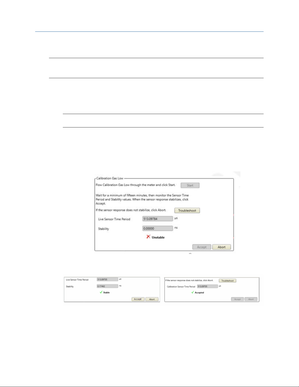
e) As the gas flows, select the Start button and observe the Live Sensor Time Period and Stability
values.
f) Wait between 3 to 15 minutes for the system to stabilize. When Stability is Good, select Accept
or Next.
If measurement does not stabilize after 30 minutes, select Abort and troubleshoot the problem.
g) Disconnect the lower calibration gas.
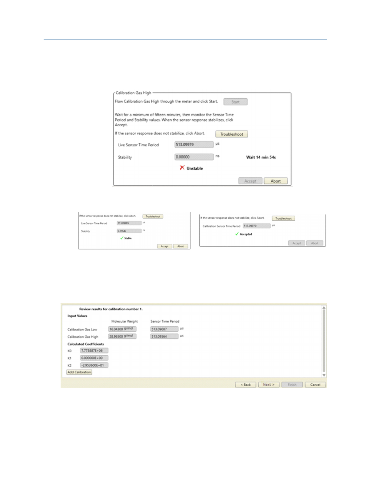
9. Set the high-density calibration point.
a) Connect the higher calibration gas to the calibration gas 2 inlet (I).
Configuration and Use Manual 39
Purging and calibration Configuration and Use Manual
March 2021 MMI-20020954
b) Make sure the process/calibration selector valve (B) remains on the calibration position.
c) As the gas flows, select the Start button and observe the Sensor Time Period and Stability
values.
d) Wait between 3 to 15 minutes for the system to stabilize. When Stability is Good, select Accept
or Next.
If measurement does not stabilize after 30 minutes, select Abort and troubleshoot the problem.
e) Disconnect the calibration gas.
10. Select Next.
11. Review the results for this calibration.
12. Select Finish to save the results and exit, or select Add Calibration to add a calibration.
Tip
You can use Add Calibration to create a new set of calibration coefficients.
13. Set Active Calibration to the calibration to be used for measurement.
40 Micro Motion Gas Specific Gravity Meters (SGM)
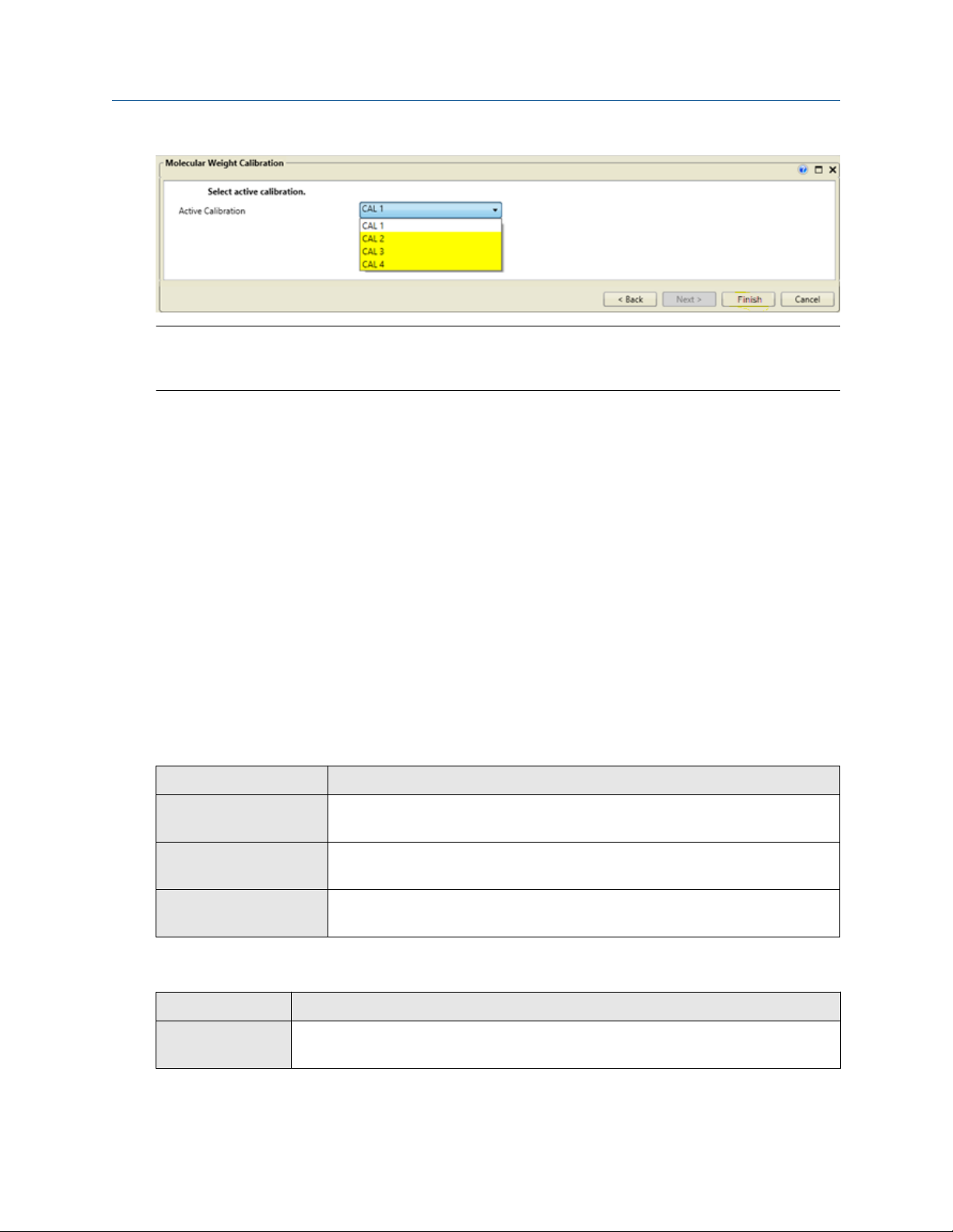
Configuration and Use Manual Purging and calibration
MMI-20020954 March 2021
Tip
You can also set Active Calibration from the Calibration Data window. This allows you to change the
calibration without going through the calibration wizard.
For 2-point calibrations, two calibration coefficients (K0 and K2) are calculated and used in
measurement.
14. The SGM is ready to be used. Shut off the calibration gas regulators and set the process/calibration
selector valve (B) to the process gas position and open the process gas inlet valve (D) to let process gas
flow through the system and be measured.
Related information
Functional view of the SGM
Verify the SGM calibration
5.4.3 Calibrate the SGM device using a field communicator
Procedure
1. Read the Prerequisites in Calibrate the SGM device if you have not already done so.
2. Choose Configure → Manual Setup → Measurements → Optional Setup → Gas Meter Calibration.
3. Set the measurement type for this device and press Send.
Option
Specific Gravity Meter Gas density will be measured as specific gravity, and specific gravity will be
Molecular Weight Meter Gas density will be measured as molecular weight, and molecular weight
Relative Density Meter Gas density will be measured as relative density, and relative density will be
4. Set the calibration type (calibration format).
Description
used for calibration.
will be used for calibration.
used for calibration.
Option
2-Point Calibration Appropriate for gases with two main constituents. Requires two calibration
Configuration and Use Manual 41
Description
gases.

Purging and calibration Configuration and Use Manual
March 2021 MMI-20020954
Option Description
3-Point Calibration Appropriate for gases with three main constituents. Use only if recommended by
customer support. For more information, see Three-point calibration.
5. Select the number of the calibration that you want to perform and select Send.
NOTICE
If the information is not sent, then the calibration gas information is not set correctly and the
corresponding K factors will not be calculated.
The device can store up to four independent calibration ranges. All calibrations must have the same
calibration type (2-point or 3-point). Each calibration can use different calibration gases.
6. Enter data for each calibration gas.
a) Choose Setup Calibration and choose the calibration gas you are describing.
b) Select the calibration gas from the list for Calibration Gas Low and Calibration Gas High. If it is
not listed, select Other.
c) Enter the specific gravity, molecular weight, or relative density of the calibration gas for
Calibration Gas Low and Calibration Gas High.
Tip
Enter the calibration gases in order of density, from lowest to highest. This allows heavier gases to
replace lighter gases.
7. Set the low-density calibration point. See Figure 5-2.
a) Connect the lower calibration gas to the calibration gas inlet 1 (H).
b) Set the pressure regulator on the lower calibration gas tank to the appropriate sample pressure
for your installation.
Note
Make sure the process gas inlet valve (D) is closed.
c) Set the gas selector valve (A) to the calibration gas inlet 1 position and open the outlet valve (C).
d) Choose Start Calibration and choose the calibration gas you are using, then select OK.
e) As the gas flows, select the Start button and observe the Sensor Time Period and Stability
values.
f) Wait between 3 to 15 minutes for the system to stabilize. When Calibration Point is Good, select
OK.
If measurement does not stabilize after 30 minutes, select Abort and troubleshoot the problem.
g) Close the calibration valve.
h) Disconnect the lower calibration gas.
8. Set the high-density calibration point.
a) Connect the higher calibration gas to the calibration gas 2 inlet (I).
42 Micro Motion Gas Specific Gravity Meters (SGM)

Configuration and Use Manual Purging and calibration
MMI-20020954 March 2021
b) Set the pressure regulator on the lower calibration gas to the appropriate sample pressure for
your installation.
c) Set the calibration gas selector valve (A) to the calibration gas 2 inlet (I) position. The process
gas inlet valve (D) must remain closed.
d) Choose Start Calibration and choose the calibration gas you are using, then select OK.
e) As the gas flows, select the Start button and observe the Sensor Time Period and Stability
values.
f) Wait between 3 to 15 minutes for the system to stabilize. When Calibration Point is Good, select
OK.
If measurement does not stabilize after 30 minutes, select Abort and troubleshoot the problem.
g) Disconnect the calibration gas.
9. Choose Results to review the results for this calibration.
If you want to recalculate one or more of the calibration points, select Back and repeat the step.
10. Optional: To add a calibration, return to the first step and repeat this procedure.
Restriction
The additional calibrations must use the same measurement type and calibration type.
11. Choose Configure → Manual Setup → Measurements → Gas Calibration and set Active Calibration
to the calibration to be used for measurement.
For 2-point calibrations, two calibration coefficients (K0 and K2) are calculated and used in measurement.
Postrequisites
To restore normal gas flow, set the process/calibration gas selector valve (B) to the process gas position and
open the process gas inlet valve (D).
Related information
Functional view of the SGM
Verify the SGM calibration
5.4.4 Verify the SGM calibration
If one of the calibration point measurements does not stabilize within 30 minutes, abort the calibration and
check for problems.
Typical problems include the following:
• The calibration gas is not flowing. Ensure that the pressure of the calibration gas is 15% to 25% higher than
the reference chamber pressure, then check for obstructions in the gas path.
• The reference chamber or the gas path is leaking. Check for leakage.
• Verify that the purge valve and pipework connections are correct.
Depending on the problem, you may be able to restart the calibration at the abort point.
Configuration and Use Manual 43

Purging and calibration Configuration and Use Manual
March 2021 MMI-20020954
Related information
Check for leakage
5.5 Review data for all calibrations
ProLink III Device Tools → Calibration Data
Field communicator Configure → Manual Setup → Calibration Factors
For all calibrations, you can review the gas data and sensor time period data that was used to calculate the
calibration factors, and you can review the calibration factors.
5.6 Change the label for the active calibration
ProLink III Device Tools → Calibration Data
Field communicator Configure → Manual Setup → Calibration Factors
You can change the default calibration labels.
Procedure
1. Select and delete the value in the Calibration x Label field.
2. Enter your preferred calibration label and press Apply.
5.7 Select the active calibration
ProLink III
Field communicator Configure → Manual Setup → Measurements → Gas Calibration → Active Calibration
The SGM can store up to four calibrations. The active calibration specifies the calibration to be used for
measurement.
Important
Do not confuse the active calibration with the calibration being performed. For example, you may perform
Calibration 4, and then choose to use Calibration 3 for measurement.
Procedure
Set Active Calibration to the calibration you want to use for measurement.
Related information
Device Tools → Calibration Data → Active Calibration
Review data for all calibrations
44 Micro Motion Gas Specific Gravity Meters (SGM)

Configuration and Use Manual Configure measurement units using the display
MMI-20020954 March 2021
6 Configure measurement units using the display
Restriction
The display allows you to configure measurement units, but does not support any other process
measurement configuration. To access all process measurement parameters, you must use one of the
following:
• ProLink III
• Field communicator
6.1 Configure measurement units using the display
The measurement unit parameters specify the units that will be used for process variables.
Procedure
1. Navigate to the Off-Line Maintenance menu and enter it.
2. Activate Scroll until OFF-LINE CONFIG appears, then activate Select.
3. When CONFIG UNITS appears, activate Select.
4. Set the units.
a) When the first process variable appears, activate Select.
b) Activate Scroll to scroll through the options for that process variable.
c) When the desired unit appears, activate Select.
d) Activate Select to store your choice.
e) Repeat until you have set measurement units for all process variables.
5. When EXIT appears, activate Select to return to the higher-level menu.
Configuration and Use Manual 45

Configure measurement units using the display Configuration and Use Manual
March 2021 MMI-20020954
46 Micro Motion Gas Specific Gravity Meters (SGM)

Configuration and Use Manual Configure process measurement using ProLink III
MMI-20020954 March 2021
7 Configure process measurement using ProLink III
7.1 Configure specific gravity, molecular weight, or relative density parameters using ProLink III
These parameters control the measurement of the primary process variable.
Related information
Configure Damping using ProLink III
Configure the molecular weight of air using ProLink III
7.1.1 Configure Damping using ProLink III
ProLink III Device Tools → Configuration → Process Measurement → Specific Gravity → Damping
Device Tools → Configuration → Process Measurement → Molecular Weight → Damping
Device Tools → Configuration → Process Measurement → Relative Density → Damping
Damping controls the amount of damping that will be applied to the primary process variable: specific
gravity, molecular weight, or relative density.
Damping is used to smooth out small, rapid fluctuations in process measurement. Damping Value specifies
the time period (in seconds) over which the transmitter will spread changes in the process variable. At the end
of the interval, the internal value will reflect 63% of the change in the actual measured value.
Tip
Damping affects all process variables that are calculated from the primary process variable: specific gravity,
molecular weight, or relative density.
Procedure
Set Damping to the value you want to use.
The default value is 0 seconds. The range is 0 to 440 seconds.
Interaction between Damping and Added Damping
When the mA Output is configured to report the primary process variable (specific gravity, molecular weight,
or relative density), both Damping and Added Damping are applied to the reported value.
Damping controls the rate of change in the value of the process variable in transmitter memory. Added
Damping controls the rate of change reported via the mA Output.
If mA Output Process Variable is set to Specific Gravity, Molecular Weight, or Relative Density, and both
Damping and Added Damping are set to non-zero values, the primary process variable damping is applied
first, and the added damping calculation is applied to the result of the first calculation. This value is reported
over the mA Output.
Configuration and Use Manual 47
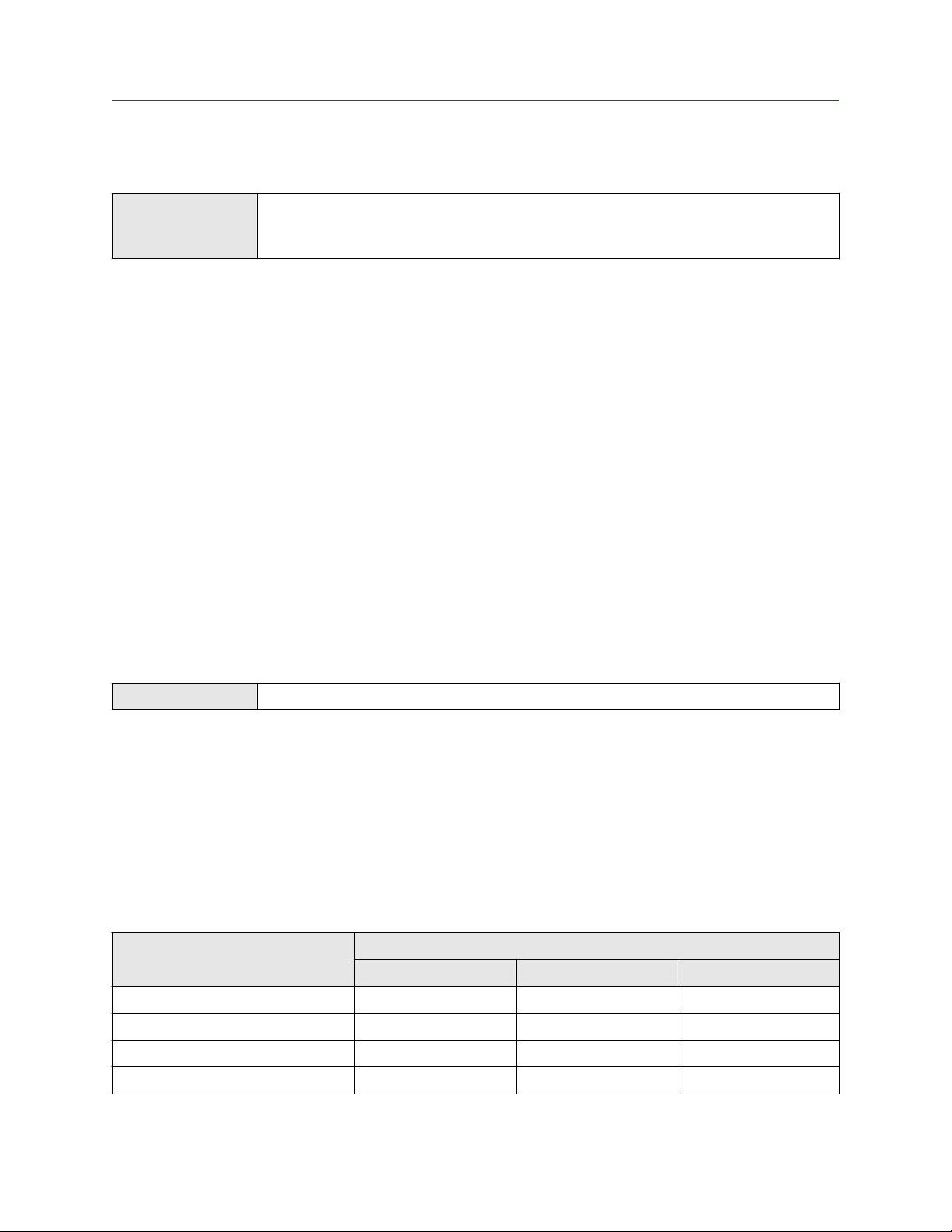
Configure process measurement using ProLink III Configuration and Use Manual
March 2021 MMI-20020954
7.1.2 Configure the molecular weight of air using ProLink III
ProLink III Device Tools → Configuration → Process Measurement → Specific Gravity → Molecular Weight of Air
Device Tools → Configuration → Process Measurement → Molecular Weight → Molecular Weight of Air
Device Tools → Configuration → Process Measurement → Relative Density → Molecular Weight of Air
The molecular weight of air is required for several different gas measurements. For most applications, the
default value can be used.
Procedure
Set Molecular Weight of Air to the value to be used in your application.
The default value is 28.95459 g/mol. This value is appropriate for most applications.
7.2 Configure temperature measurement using ProLink III
The temperature measurement parameters control how temperature is measured and reported.
Related information
Configure Temperature Unit using ProLink III
Configure Temperature Damping using ProLink III
Configure Temperature Input using ProLink III
7.2.1 Configure Temperature Unit using ProLink III
ProLink III
Temperature Unit specifies the unit that will be used for temperature measurement.
Procedure
Set Temperature Unit to the option you want to use.
The default setting is Degrees Celsius.
Options for Temperature Measurement Unit
The transmitter provides a standard set of units for Temperature Measurement Unit. Different
communications tools may use different labels for the units.
Unit description
Device Tools → Configuration → Process Measurement → Sample Temperature → Temperature Unit
Label
Display ProLink III Field communicator
Degrees Celsius °C °C degC
Degrees Fahrenheit °F °F degF
Degrees Rankine °R °R degR
Kelvin °K °K Kelvin
48 Micro Motion Gas Specific Gravity Meters (SGM)

Configuration and Use Manual Configure process measurement using ProLink III
MMI-20020954 March 2021
7.2.2 Configure Temperature Damping using ProLink III
ProLink III Device Tools → Configuration → Process Measurement → Sample Temperature → Temperature
Damping
Temperature Damping controls the amount of damping that will be applied to the sample temperature
value, when the on-board temperature data is used (RTD).
Damping is used to smooth out small, rapid fluctuations in process measurement. Damping Value specifies
the time period (in seconds) over which the transmitter will spread changes in the process variable. At the end
of the interval, the internal value will reflect 63% of the change in the actual measured value.
Tip
Temperature Damping affects all process variables, compensations, and corrections that use temperature
data from the sensor.
Procedure
Enter the value you want to use for Temperature Damping.
The default value is 4.8 seconds. The range is 0 to 38.4 seconds.
Tip
• A high damping value makes the process variable appear smoother because the reported value changes
slowly.
• A low damping value makes the process variable appear more erratic because the reported value changes
more quickly.
• Whenever the damping value is non-zero, the reported measurement will lag the actual measurement
because the reported value is being averaged over time.
• In general, lower damping values are preferable because there is less chance of data loss, and less lag time
between the actual measurement and the reported value.
The value you enter is automatically rounded to the nearest valid value. Valid values for Temperature
Damping are 0, 0.6, 1.2, 2.4, 4.8, … 38.4.
7.2.3 Configure Temperature Input using ProLink III
ProLink III
Procedure
1. Choose the method to be used to supply temperature data, and perform the required setup.
Option
Internal RTD
temperature data
Device Tools → Configuration → Process Measurement → Sample Temperature → Sample Temperature
Source
Description Setup
Temperature data from the onboard temperature sensor
(RTD) is used.
a. Set Sample Temperature Source to Internal RTD.
b. Click Apply.
Configuration and Use Manual 49
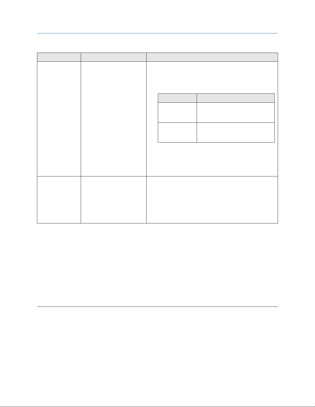
Configure process measurement using ProLink III Configuration and Use Manual
March 2021 MMI-20020954
Option Description Setup
Polling The meter polls an external
device for temperature data.
This data will be available in
addition to the internal RTD
temperature data.
Digital
communications
A host writes temperature data
to the meter at appropriate
intervals. This data will be
available in addition to the
internal RTD temperature data.
a. Set Sample Temperature Source to Poll for External Value.
b. Set Polling Slot to an available slot.
c. Set Polling Control to Poll as Primary or Poll as Secondary.
Option Description
Poll as Primary No other HART masters will be on the
network. A field communicator is not
a HART master.
Poll as Secondary Other HART masters will be on the
network. A field communicator is not
a HART master.
d. Set External Device Tag to the HART tag of the
temperature device.
e. Select Apply.
a. Set Sample Temperature Source to Fixed Value or Digital
Communications.
b. Select Apply.
c. Perform the necessary host programming and
communications setup to write temperature data to the
meter at appropriate intervals.
2. If you set up an external temperature:
a) Choose Device Tools → Configuration → I/O → Inputs → External Inputs.
b) In the Sample Temperature Input group, check or uncheck the checkboxes as desired.
If a checkbox is checked, the internal temperature is used for that measurement or calculation. If
a checkbox is unchecked, the external temperature is used.
Postrequisites
If you are using external temperature data, verify the external temperature value displayed in the Inputs group
on the ProLink III main window.
Need help?
If the value is not correct:
• For polling:
— Verify the wiring between the meter and the external device.
— Verify the HART tag of the external device.
• For digital communications:
— Verify that the host has access to the required data.
50 Micro Motion Gas Specific Gravity Meters (SGM)

Configuration and Use Manual Configure process measurement using ProLink III
MMI-20020954 March 2021
— Verify that the host is writing to the correct register in memory, using the correct data type.
7.3 Configure the pressure input
Pressure data is required to calculate base density from line density. The meter does not measure pressure, so
you must provide an external pressure input. You must use absolute pressure.
Pressure data is required for several different measurements. There are several different methods to obtain
pressure data.
Tip
A fixed value for temperature is not recommended. Using a fixed temperature value may produce inaccurate
process data.
Prerequisites
If you plan to poll an external device:
• The primary mA output must be wired to support HART communications.
• Ensure that the meter has the required polling slots available. The meter provides four polling slots, and
they may be already in use. You may need to use a fixed value or digital communications for some external
values. To check the current polling configuration, choose Device Tools → Configuration → Polled
Variables.
7.3.1 Configure the pressure input using ProLink III
Procedure
1. Choose Device Tools → Configuration → Process Measurement → Line Pressure.
2. Set Pressure Type to match the pressure measurement from the external pressure device.
Option
Absolute The external pressure device reports absolute pressure.
Gauge The external pressure device reports gauge pressure.
Restriction
If Line Pressure Source is set to Fixed, you cannot configure Pressure Type. You must enter the
pressure value in the required form. To set Pressure Type, you may need to change the setting of Line
Pressure Source.
The meter requires absolute pressure. If you select Gauge, the device will convert the input pressure
value to the equivalent absolute pressure.
3. Set Pressure Unit to the unit used by the external pressure device.
4. Choose the method used to supply pressure data and perform the required setup.
Description
Configuration and Use Manual 51
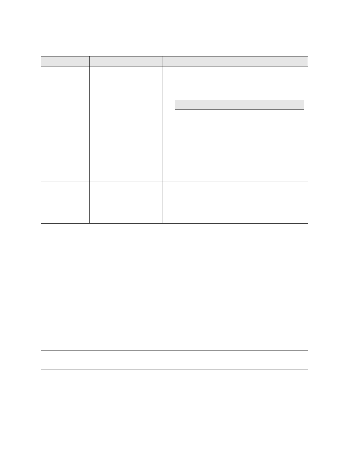
Configure process measurement using ProLink III Configuration and Use Manual
March 2021 MMI-20020954
Option Description Setup
Polling The meter polls an external
device for pressure data.
Digital
communications
A host writes pressure data to
the meter at appropriate
intervals.
a. Set Pressure Source to Poll for External Value.
b. Set Polling Slot to an available slot.
c. Set Polling Control to Poll as Primary or Poll as Secondary.
Option Description
Poll as Primary No other HART masters will be on the
network. A field communicator is not
a HART master.
Poll as Secondary Other HART masters will be on the
network. A field communicator is not
a HART master.
d. Set External Device Tag to the HART tag of the
temperature device.
a. Set Pressure Source to Fixed Value or Digital
Communications.
b. Perform the necessary host programming and
communications setup to write pressure data to the meter
at appropriate intervals.
Postrequisites
The current pressure value is displayed in the External Pressure field. Verify that the value is correct.
Need help?
If the value is not correct:
• Ensure that the external device and the meter are using the same measurement unit.
• For polling:
— Verify the wiring between the meter and the external device.
— Verify the HART tag of the external device.
• For digital communications:
— Verify that the host has access to the required data.
— Verify that the host is writing to the correct register in memory, using the correct data type.
• If necessary, apply an offset.
Note
Do not use the offset in conjunction with the fixed pressure value. Enter the adjusted value.
52 Micro Motion Gas Specific Gravity Meters (SGM)

Configuration and Use Manual Configure process measurement using ProLink III
MMI-20020954 March 2021
7.4 Configure gas compressibility measurement using
ProLink III
ProLink III Device Tools → Configuration → Process Measurement → Compressibility
Gas compressibility measurement is required for the following process variables: line density, calorific value,
Wobbe index, and energy flow. Gas compressibility measurement can also be used to calculate
compressibility as an independent process variable.
Prerequisites
• You must know whether you will measure line compressibility and base compressibility or you will use
fixed values.
• If you will use fixed values, you must know the line compressibility and base compressibility values for your
application.
• If you will measure compressibility, you must be able to supply gas composition data to the meter, for the
following constituents:
— Carbon dioxide (CO2)
— Nitrogen (N2)
— Hydrogen (H2) (required only if you plan to measure compressibility according to SGERG 88)
• Gas composition must be measured in % by volume.
• If you plan to poll an external device for % CO2, % N2, or % H2, ensure that the meter has the required
polling slots available. The meter provides four polling slots, and they may be already in use. You may need
to use a fixed value or digital communications for some external values. To check the current polling
configuration, choose Device Tools → Configuration → Polled Variables.
Procedure
1. Choose Device Tools → Configuration → Process Measurement → Compressibility.
2. Set Compressibility Calculations as desired, and click Apply.
Option
Disabled The meter will not calculate compressibility. You must enter fixed values for line
Enabled The meter will calculate line compressibility and base compressibility. You must provide
3. If you set Compressibility Calculations to Disabled:
a) Set Line Compressibility to the compressibility of your sample gas at line temperature and line
Description
compressibility and base compressibility.
gas composition data.
pressure.
The default value is 0. The range is 0.7 to 1.1.
b) Set Base Compressibility to the compressibility of your sample gas at base temperature and
base pressure.
Configuration and Use Manual 53

Configure process measurement using ProLink III Configuration and Use Manual
March 2021 MMI-20020954
The default value is 1.0. The range is 0.7 to 1.1.
c) Click Apply. No further actions are required.
4. If you set Compressibility Calculations to Enabled, complete the configuration as described in the
following steps.
5. Select the compressibility measurement method that you want to use or that meets site standards.
Important
• Different options are available depending on your primary process variable: specific gravity,
molecular weight, or relative density.
• If you choose AGA NX 19 Mod 3 or SGERG 88, you must set up energy content measurement. If you
choose any other method, energy content measurement is required only if you want the meter to
report calorific value, Wobbe index, or energy flow.
• Each compressibility measurement method has associated process limits. If your process goes
outside the valid range, compressibility will be reported as NaN (Not a Number), and all process
variables that require a calculated compressibility value will also be reported as NaN.
6. Set % CO2 Source to the method you will use to supply % CO2 data, and perform the required setup.
Option Description Setup
Polling The meter polls an external
device for % CO2 data.
Digital
communications
Fixed value The configured fixed value is
A host writes % CO2 data to the
meter at appropriate intervals.
used.
a. Set % CO2 Source to Poll for External Value.
b. Set Polling Slot to an available slot.
c. Set Polling Control to Poll as Primary or Poll as Secondary.
d. Set External Device Tag to the HART tag of the % CO2
measurement device.
a. Set % CO2 Source to Fixed Value or Digital
Communications.
b. Perform the necessary host programming and
communications setup to write % CO2 data to the meter at
appropriate intervals.
a. Set % CO2 Source to Fixed Value or Digital
Communications.
b. Set % CO2 (Fixed) to the desired value, in % by volume.
7. Set % N2 Source to the method you will use to supply % N2 data, and perform the required setup.
54 Micro Motion Gas Specific Gravity Meters (SGM)

Configuration and Use Manual Configure process measurement using ProLink III
MMI-20020954 March 2021
Option Description Setup
Polling The meter polls an external
device for % N2 data.
Digital
communications
Fixed value The configured fixed value is
A host writes % N2 data to the
meter at appropriate intervals.
used.
a. Set % N2 Source to Poll for External Value.
b. Set Polling Slot to an available slot.
c. Set Polling Control to Poll as Primary or Poll as Secondary.
d. Set External Device Tag to the HART tag of the % N2
measurement device.
a. Set % N2 Source to Fixed Value or Digital Communications.
b. Perform the necessary host programming and
communications setup to write % N2 data to the meter at
appropriate intervals.
a. Set % N2 Source to Fixed Value or Digital Communications.
b. Set % N2 (Fixed) to the desired value, in % by volume.
8. If you set Compressibility Measurement Method to SGERG 88, set % H2 Source to the method you
will use to supply % H2 data, and perform the required setup.
Option Description Setup
Polling The meter polls an external
device for % H2 data.
a. Set % H2 Source to Poll for External Value.
b. Set Polling Slot to an available slot.
Digital
communications
Fixed value The configured fixed value is
A host writes % H2 data to the
meter at appropriate intervals.
used.
c. Set Polling Control to Poll as Primary or Poll as Secondary.
d. Set External Device Tag to the HART tag of the % H2
measurement device.
a. Set % H2 Source to Fixed Value or Digital Communications.
b. Perform the necessary host programming and
communications setup to write % H2 data to the meter at
appropriate intervals.
a. Set % H2 Source to Fixed Value or Digital Communications.
b. Set % H2 (Fixed) to the desired value, in % by volume.
Configuration and Use Manual 55
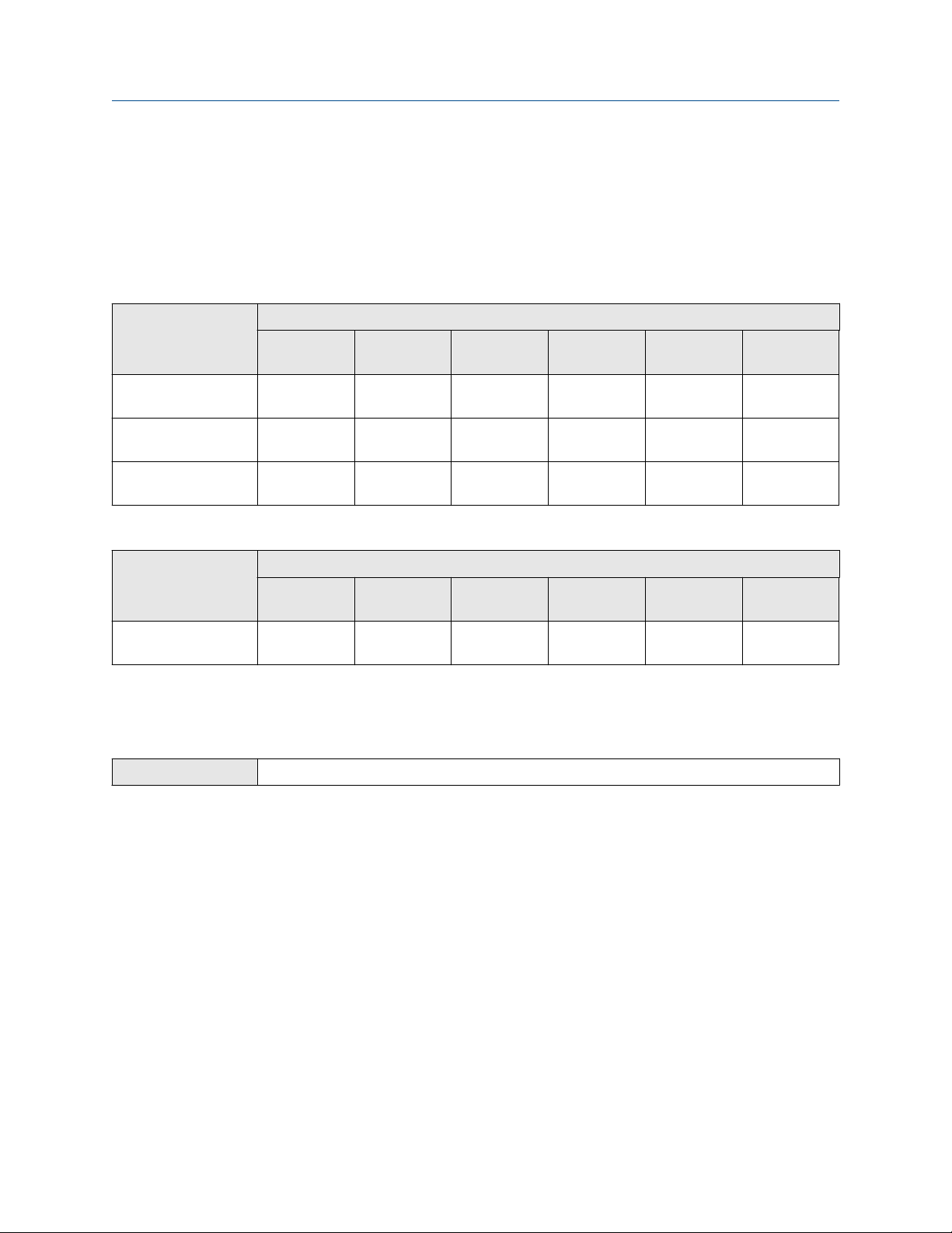
Configure process measurement using ProLink III Configuration and Use Manual
March 2021 MMI-20020954
7.4.1 Compressibility Method and process limits
Each method for calculating compressibility has specific limits for line temperature, line pressure, and other
process variables. If your process goes outside the valid range, compressibility will be reported as NaN (Not a
Number). All process variables that require compressibility will also be reported as NaN.
Table 7-1: Specific gravity and molecular weight meters: Compressibility Method and valid ranges for
process variables
Compressibility
Method
AGA NX-19 −40 to
AGA NX-19 Mod −40 to
AGA NX-19 Mod 3 0 to 30 °C 0 to 80 BarA 0.554 to
Temperature Pressure Specific
gravity
+115.556 °C
+115.556 °C
1.01325 to
345.751 BarA
0 to 137.9
BarA
0.55 to 1 0–15% 0–15% 0–15%
0.554 to 0.75 0–15% 0–15% N/A
0.691
Valid range
% CO2 % N2 % H2
0–2.50% 0–7% 0–4%
Table 7-2: Relative density meters: Compressibility Method and valid ranges for process variables
Compressibility
Method
SGERG-88 −30 to
(1) The sum of CO2 and N2 must be less than 50%.
Temperature Pressure Relative
0 to 120 BarA 0.55 to 0.9 0–30%
+100 °C
density
Valid range
% CO2 % N2 % H2
(1)
0–50%
(1)
N/A
7.5 Configure base density calculations using ProLink III
ProLink III
Device Tools → Configuration → Process Measurement → Base Density
The base density parameters provide data for the base density calculations. Base density can be reported as a
process variable. For specific gravity meters and relative density meters, base density is required for line
density measurement.
Procedure
1. Choose Device Tools → Configuration → Process Measurement → Base Density.
2. Set Density Unit to the unit to be used for base density, and click Apply.
This unit is also used for line density.
3. Set Base Pressure to the pressure value to which density measurements will be corrected (the
reference pressure).
The default is 1 bar absolute. There is no upper limit. You must be using absolute pressure.
This value is also used in line density measurement. Be sure that the value is appropriate for both
process variables.
56 Micro Motion Gas Specific Gravity Meters (SGM)

Configuration and Use Manual Configure process measurement using ProLink III
MMI-20020954 March 2021
4. Set Base Temperature to the temperature value to which density measurements will be corrected (the
reference temperature).
The default is 20 °C. The range is −50 °C to +200 °C.
This value is also used in line density measurement. Be sure that the value is appropriate for both
process variables.
5. (Relative density meters only) Set Density of Air to the value to be used in your application.
Enter the value in the configured measurement unit. The default is 0.000122305 g/cm³. The range is
0.0001 g/cm³ to 0.00015 g/cm³.
7.5.1 Options for Density Measurement Unit
The transmitter provides a standard set of measurement units for Density Measurement Unit. Different
communications tools may use different labels.
Label
Unit description
Grams per cubic centimeter G/CM3 g/cm3 g/Cucm
Grams per liter G/L g/l g/L
Grams per milliliter G/mL g/ml g/mL
Kilograms per liter KG/L kg/l kg/L
Kilograms per cubic meter KG/M3 kg/m3 kg/Cum
Pounds per U.S. gallon LB/GAL lbs/Usgal lb/gal
Pounds per cubic foot LB/CUF lbs/ft3 lb/Cuft
Pounds per cubic inch LB/CUI lbs/in3 lb/CuIn
Short ton per cubic yard ST/CUY sT/yd3 STon/Cuyd
Degrees API D API degAPI degAPI
Special unit SPECL special Spcl
Display ProLink III Field communicator
7.5.2 Define a special measurement unit for density
ProLink III
Field communicator Configure → Manual Setup → Measurements → Optional Setup → Special Units
A special measurement unit is a user-defined unit of measure that allows you to report process data in a unit
that is not available in the transmitter. A special measurement unit is calculated from an existing
measurement unit using a conversion factor.
Device Tools → Configuration → Process Measurement → Line Density → Special Units
Procedure
1. Specify Density Special Unit Base.
Density Special Unit Base is the existing density unit that the special unit will be based on.
Configuration and Use Manual 57

Configure process measurement using ProLink III Configuration and Use Manual
March 2021 MMI-20020954
2. Calculate Density Special Unit Conversion Factor as follows:
a) x base units = y special units
b) Density Special Unit Conversion Factor = x÷y
3. Enter Density Special Unit Conversion Factor.
The original density value is divided by this conversion factor.
4. Set User-Defined Label to the name you want to use for the density unit.
The special measurement unit is stored in the transmitter. You can configure the transmitter to use the
special measurement unit at any time.
Defining a special measurement unit for density
You want to measure density in ounces per cubic inch.
1. Set Density Special Unit Base to g/cm3.
2. Calculate Density Special Unit Conversion Factor:
a. 1 g/cm3 = 0.578 oz/in3
b. 1÷0.578 = 1.73
3. Set Density Special Unit Conversion Factor to 1.73.
4. Set User-Defined Label to oz/in3.
7.6 Configure line density calculations using ProLink III
ProLink III
The line density parameters provide data for line density measurement. Line density can be reported as a
process variable. Line density is required to measure calorific value and energy flow.
Procedure
1. Choose Device Tools → Configuration → Process Measurement → Line Density.
2. Set Density Unit to the unit to be used for line density, and click Apply.
This unit is also used for base density.
3. Verify the value of Line Pressure.
4. Verify the value of Sample Temperature.
5. Set Base Pressure to the pressure value to which density measurements will be corrected (the
reference pressure).
Device Tools → Configuration → Process Measurement → Line Density
The default is 1 bar absolute. There is no upper limit. You must be using absolute pressure.
This value is also used in base density measurement. Be sure that the value is appropriate for both
process variables.
6. Set Base Temperature to the temperature value to which density measurements will be corrected (the
reference temperature).
58 Micro Motion Gas Specific Gravity Meters (SGM)

Configuration and Use Manual Configure process measurement using ProLink III
MMI-20020954 March 2021
The default is 20 °C. The range is −50 °C to +200 °C.
This value is also used in base density measurement. Be sure that the value is appropriate for both
process variables.
7. (Relative density meters only) Set Density of Air to the value to be used in your application.
The default is 0.000122305 g/cm³. The range is 0.0001 g/cm³ to 0.00015 g/cm³.
7.7 Configure energy content measurement using ProLink III
ProLink III Device Tools → Configuration → Process Measurement → Calorific Value/BTU/Wobbe Index/Energy
The energy content parameters are used to measure and calculate calorific value, Wobbe index, and energy
flow.
Prerequisites
You must be able to supply gas composition data to the meter, for the following constituents:
• Carbon monoxide (CO)
• Carbon dioxide (CO2)
• Nitrogen (N2)
• Hydrogen (H2)
Gas composition must be measured in % by volume.
If you plan to measure energy flow, you must be able to supply flow data to the meter. You have the following
options:
• If you are using an external volume flow device, Volume Flow (External) and Mass Flow (Calculated) are
available.
• If you are using an external mass flow device, Mass Flow (External) and Volume Flow (Calculated) are
available.
Tip
In either case, you can measure energy flow in either mass units or volume units. The meter automatically
selects the appropriate process variable.
Flow
If you plan to poll an external device for any of these, ensure that the meter has the required polling slots
available. The meter provides four polling slots, and they may be already in use. You may need to use a fixed
value or digital communications for some external values. To check the current polling configuration, choose
Device Tools → Configuration → Polled Variables. If you are already polling for one of these, you can use the
existing polled data.
Procedure
1. Choose Device Tools → Configuration → Process Measurement → Calorific Value/BTU/Wobbe
Index/Energy Flow.
2. Set Calorific Value Units to the unit to be used to measure energy content.
Configuration and Use Manual 59

Configure process measurement using ProLink III Configuration and Use Manual
March 2021 MMI-20020954
3. Set % CO Source to the method you will use to supply % CO data, and perform the required setup.
Option Description Setup
Polling The meter polls an external
device for % CO data.
Digital
communications
Fixed value The configured fixed value is
A host writes % CO data to the
meter at appropriate intervals.
used.
a. Set % CO Source to Poll for External Value.
b. Set Polling Slot to an available slot.
c. Set Polling Control to Poll as Primary or Poll as Secondary.
d. Set External Device Tag to the HART tag of the % CO
measurement device.
a. Set % CO Source to Fixed Value or Digital Communications.
b. Perform the necessary host programming and
communications setup to write % CO data to the meter at
appropriate intervals.
a. Set % CO Source to Fixed Value or Digital Communications.
b. Set % CO (Fixed) to the desired value, in % by volume.
4. Set % CO2 Source to the method you will use to supply % CO2 data, and perform the required setup.
Option Description Setup
Polling The meter polls an external
device for % CO2 data.
a. Set % CO2 Source to Poll for External Value.
b. Set Polling Slot to an available slot.
c. Set Polling Control to Poll as Primary or Poll as Secondary.
d. Set External Device Tag to the HART tag of the % CO2
measurement device.
Digital
communications
Fixed value The configured fixed value is
A host writes % CO2 data to the
meter at appropriate intervals.
used.
a. Set % CO2 Source to Fixed Value or Digital
Communications.
b. Perform the necessary host programming and
communications setup to write % CO2 data to the meter at
appropriate intervals.
a. Set % CO2 Source to Fixed Value or Digital
Communications.
b. Set % CO2 (Fixed) to the desired value, in % by volume.
5. Set % N2 Source to the method you will use to supply % N2 data, and perform the required setup.
60 Micro Motion Gas Specific Gravity Meters (SGM)

Configuration and Use Manual Configure process measurement using ProLink III
MMI-20020954 March 2021
Option Description Setup
Polling The meter polls an external
device for % N2 data.
Digital
communications
Fixed value The configured fixed value is
A host writes % N2 data to the
meter at appropriate intervals.
used.
a. Set % N2 Source to Poll for External Value.
b. Set Polling Slot to an available slot.
c. Set Polling Control to Poll as Primary or Poll as Secondary.
d. Set External Device Tag to the HART tag of the % N2
measurement device.
a. Set % N2 Source to Fixed Value or Digital Communications.
b. Perform the necessary host programming and
communications setup to write % N2 data to the meter at
appropriate intervals.
a. Set % N2 Source to Fixed Value or Digital Communications.
b. Set % N2 (Fixed) to the desired value, in % by volume.
6. Set % H2 Source to the method you will use to supply % H2 data, and perform the required setup.
Option Description Setup
Polling The meter polls an external
device for % H2 data.
a. Set % H2 Source to Poll for External Value.
b. Set Polling Slot to an available slot.
a. Set Polling Control to Poll as Primary or Poll as Secondary.
b. Set External Device Tag to the HART tag of the % H2
measurement device.
Digital
communications
Fixed value The configured fixed value is
A host writes % H2 data to the
meter at appropriate intervals.
used.
a. Set % H2 Source to Fixed Value or Digital Communications.
b. Perform the necessary host programming and
communications setup to write % H2 data to the meter at
appropriate intervals.
a. Set % H2 Source to Fixed Value or Digital Communications.
b. Set % H2 (Fixed) to the desired value, in % by volume.
7. Optional: To configure Volume Flow (External) and Mass Flow (Calculated):
a) Set Energy Flow Units to the unit to be used to measure energy flow.
b) Set Mass Flow (Calculated) to Enabled.
c) Set Standard Volume Flow Rate Units to the units used by the external volume measurement
device
d) set Volume Flow Source to the method you will use to supply volume flow data, and perform
the required setup.
Configuration and Use Manual 61

Configure process measurement using ProLink III Configuration and Use Manual
March 2021 MMI-20020954
Option Description Setup
Polling The meter polls an external
device for volume flow data
and calculates the equivalent
mass flow.
Digital
communications
Fixed value The configured fixed value is
A host writes volume flow data
to the meter at appropriate
intervals, and the meter
calculates the equivalent mass
flow.
used for volume flow, and the
meter calculates the equivalent
mass flow.
1. Set Volume Flow Source to Poll for External Value.
2. Set Polling Slot to an available slot.
3. Set Polling Control to Poll as Primary or Poll as Secondary.
4. Set External Device Tag to the HART tag of the volume
flow measurement device.
1. Set Volume Flow Source to Fixed Value or Digital
Communications.
2. Perform the necessary host programming and
communications setup to write volume flow data to the
meter at appropriate intervals.
1. Set Volume Flow Source to Fixed Value or Digital
Communications.
2. Set Volume Flow (Fixed) to the desired value.
8. Optional: To configure Mass Flow (External) and Volume Flow (Calculated):
a) Set Energy Flow Units to the unit to be used to measure energy flow.
b) Set Standard Volume Flow (Calculated) to Enabled.
c) Set Mass Flow Rate Units to the units used by the external mass measurement device.
d) Set Mass Flow Source to the method you will use to supply mass flow data, and perform the
required setup.
Option
Polling The meter polls an external
Digital
communications
Fixed value The configured fixed value is
Description Setup
device for mass flow data and
calculates the equivalent
volume flow.
A host writes mass flow data to
the meter at appropriate
intervals, and the meter
calculates the equivalent
volume flow.
used for mass flow, and the
meter calculates the equivalent
volume flow.
1. Set Mass Flow Source to Poll for External Value.
2. Set Polling Slot to an available slot.
3. Set Polling Control to Poll as Primary or Poll as Secondary.
4. Set External Device Tag to the HART tag of the mass flow
measurement device.
1. Set Mass Flow Source to Fixed Value or Digital
Communications.
2. Perform the necessary host programming and
communications setup to write mass flow data to the
meter at appropriate intervals.
1. Set Mass Flow Source to Fixed Value or Digital
Communications.
2. Set Mass Flow (Fixed) to the desired value.
62 Micro Motion Gas Specific Gravity Meters (SGM)

Configuration and Use Manual Configure process measurement using ProLink III
MMI-20020954 March 2021
7.8 Set up concentration measurement using ProLink III
This section guides you through the tasks required to set up, configure, and implement concentration
measurement.
7.8.1 Enable the concentration measurement application using ProLink III
The concentration measurement application must be enabled before you can perform any setup. If the
concentration measurement application was enabled at the factory, you do not need to enable it now.
Procedure
1. Choose Device Tools → Configuration → Transmitter Options.
2. Set Concentration Measurement to Enabled and click Apply.
7.8.2 Configure a concentration measurement matrix using ProLink III
A concentration measurement matrix defines the relationship between density and concentration for your
process gas. You can configure up to six matrices.
Prerequisites
You must know the primary and secondary constituents of your process gas, and the density of each
constituent in pure form.
Procedure
1. Choose Device Tools → Configuration → Process Measurement → Concentration Measurement.
2. To use a gas variable, set Gas Purity Variable to Specific Gravity, Molecular Weight, or Relative Density.
Meter
Specific gravity Specific Gravity or Molecular Weight
Molecular weight Specific Gravity or Molecular Weight
Relative density Relative Density
3. Set Matrix Being Configured to the matrix you want to configure and click Change Matrix.
4. Set Concentration Units Label to the label to use for the measurement unit.
This selection does not affect measurement. It only selects a label.
Available option
5. If you set Concentration Units to Special, enter a string for the custom label.
6. Enter a name for the matrix.
7. Enter the density of the primary constituent of your process gas, in its pure form.
8. Enter the density of the secondary constituent of your process gas, in its pure form.
9. Click Apply.
Configuration and Use Manual 63

Configure process measurement using ProLink III Configuration and Use Manual
March 2021 MMI-20020954
7.8.3 Select the active concentration matrix using ProLink III
You must select the concentration matrix to be used for measurement. Although the transmitter can store up
to six concentration matrices, only one matrix can be used for measurement at any one time.
Procedure
1. Choose Device Tools → Configuration → Process Measurement → Concentration Measurement.
2. Set Active Matrix to the matrix you want to use and click Change Matrix.
64 Micro Motion Gas Specific Gravity Meters (SGM)

Configuration and Use Manual Configure process measurement using a field communicator
MMI-20020954 March 2021
8 Configure process measurement using a field communicator
8.1 Configure density measurement using a field communicator
The density measurement parameters control how density is measured and reported.
Related information
Configure Density Measurement Unit using a field communicator
Configure Density Damping using a field communicator
8.1.1 Configure Density Measurement Unit using a field communicator
Field communicator Configure → Manual Setup → Measurements → Density → Density Unit
Density Measurement Unit controls the measurement units that will be used in gas measurement,
calculations, and reporting.
Procedure
Set Density Measurement Unit to the option you want to use.
The default setting for Density Measurement Unit is g/cm3 (grams per cubic centimeter).
Options for Density Measurement Unit
The transmitter provides a standard set of measurement units for Density Measurement Unit. Different
communications tools may use different labels.
Label
Unit description
Grams per cubic centimeter G/CM3 g/cm3 g/Cucm
Grams per liter G/L g/l g/L
Grams per milliliter G/mL g/ml g/mL
Kilograms per liter KG/L kg/l kg/L
Kilograms per cubic meter KG/M3 kg/m3 kg/Cum
Display ProLink III Field communicator
Pounds per U.S. gallon LB/GAL lbs/Usgal lb/gal
Pounds per cubic foot LB/CUF lbs/ft3 lb/Cuft
Pounds per cubic inch LB/CUI lbs/in3 lb/CuIn
Short ton per cubic yard ST/CUY sT/yd3 STon/Cuyd
Configuration and Use Manual 65

Configure process measurement using a field communicator Configuration and Use Manual
March 2021 MMI-20020954
Label
Unit description
Degrees API D API degAPI degAPI
Special unit SPECL special Spcl
Display ProLink III Field communicator
Define a special measurement unit for density
ProLink III Device Tools → Configuration → Process Measurement → Line Density → Special Units
Field communicator Configure → Manual Setup → Measurements → Optional Setup → Special Units
A special measurement unit is a user-defined unit of measure that allows you to report process data in a unit
that is not available in the transmitter. A special measurement unit is calculated from an existing
measurement unit using a conversion factor.
Procedure
1. Specify Density Special Unit Base.
Density Special Unit Base is the existing density unit that the special unit will be based on.
2. Calculate Density Special Unit Conversion Factor as follows:
a) x base units = y special units
b) Density Special Unit Conversion Factor = x÷y
3. Enter Density Special Unit Conversion Factor.
The original density value is divided by this conversion factor.
4. Set User-Defined Label to the name you want to use for the density unit.
The special measurement unit is stored in the transmitter. You can configure the transmitter to use the
special measurement unit at any time.
Defining a special measurement unit for density
You want to measure density in ounces per cubic inch.
1. Set Density Special Unit Base to g/cm3.
2. Calculate Density Special Unit Conversion Factor:
a. 1 g/cm3 = 0.578 oz/in3
b. 1÷0.578 = 1.73
3. Set Density Special Unit Conversion Factor to 1.73.
4. Set User-Defined Label to oz/in3.
8.1.2 Configure Density Damping using a field communicator
Field communicator
Configure → Manual Setup → Measurements → Density → Density Damping
66 Micro Motion Gas Specific Gravity Meters (SGM)

Configuration and Use Manual Configure process measurement using a field communicator
MMI-20020954 March 2021
Damping controls the amount of damping that will be applied to the primary process variable: specific
gravity, molecular weight, or relative density.
Damping is used to smooth out small, rapid fluctuations in process measurement. Damping Value specifies
the time period (in seconds) over which the transmitter will spread changes in the process variable. At the end
of the interval, the internal value will reflect 63% of the change in the actual measured value.
Tip
Damping affects all process variables that are calculated from the primary process variable: specific gravity,
molecular weight, or relative density.
Procedure
Set Damping to the value you want to use.
The default value is 1.6 seconds. The range is 0 to 440 seconds.
Interaction between Damping and Added Damping
When the mA Output is configured to report the primary process variable (specific gravity, molecular weight,
or relative density), both Damping and Added Damping are applied to the reported value.
Damping controls the rate of change in the value of the process variable in transmitter memory. Added
Damping controls the rate of change reported via the mA Output.
If mA Output Process Variable is set to Specific Gravity, Molecular Weight, or Relative Density, and both
Damping and Added Damping are set to non-zero values, the primary process variable damping is applied
first, and the added damping calculation is applied to the result of the first calculation. This value is reported
over the mA Output.
8.2 Configure temperature measurement using a field communicator
The temperature measurement parameters control how temperature is measured and reported.
Related information
Configure Temperature Measurement Unit using a field communicator
Configure Temperature Damping using a field communicator
8.2.1 Configure Temperature Measurement Unit using a field communicator
Field communicator
Configure → Manual Setup → Measurements → Temperature → Temperature Unit
Temperature Measurement Unit specifies the unit that will be used for temperature measurement.
Procedure
Set Temperature Measurement Unit to the option you want to use.
The default setting is Degrees Celsius.
Configuration and Use Manual 67
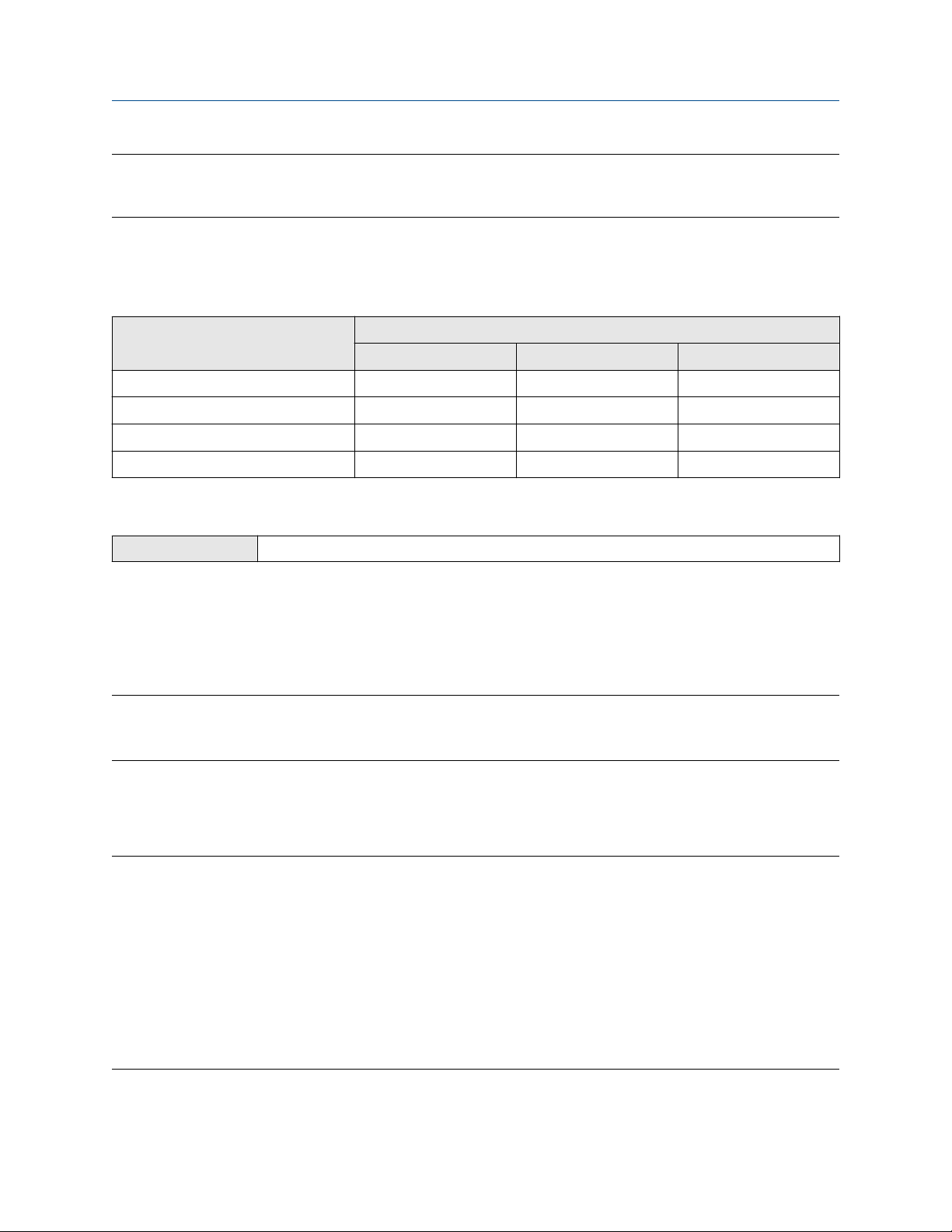
Configure process measurement using a field communicator Configuration and Use Manual
March 2021 MMI-20020954
Important
If you plan to use an external temperature device, you must set Temperature Measurement Unit to the unit
used by the external device.
Options for Temperature Measurement Unit
The transmitter provides a standard set of units for Temperature Measurement Unit. Different
communications tools may use different labels for the units.
Label
Unit description
Degrees Celsius °C °C degC
Degrees Fahrenheit °F °F degF
Degrees Rankine °R °R degR
Kelvin °K °K Kelvin
Display ProLink III Field communicator
8.2.2 Configure Temperature Damping using a field communicator
Field communicator Configure → Manual Setup → Measurements → Temperature → Temp Damping
Temperature Damping controls the amount of damping that will be applied to the sample temperature
value, when the on-board temperature data is used (RTD).
Damping is used to smooth out small, rapid fluctuations in process measurement. Damping Value specifies
the time period (in seconds) over which the transmitter will spread changes in the process variable. At the end
of the interval, the internal value will reflect 63% of the change in the actual measured value.
Tip
Temperature Damping affects all process variables, compensations, and corrections that use temperature
data from the sensor.
Procedure
Enter the value you want to use for Temperature Damping.
The default value is 4.8 seconds. The range is 0 to 38.4 seconds.
Tip
• A high damping value makes the process variable appear smoother because the reported value changes
slowly.
• A low damping value makes the process variable appear more erratic because the reported value changes
more quickly.
• Whenever the damping value is non-zero, the reported measurement will lag the actual measurement
because the reported value is being averaged over time.
• In general, lower damping values are preferable because there is less chance of data loss, and less lag time
between the actual measurement and the reported value.
The value you enter is automatically rounded to the nearest valid value. Valid values for Temperature
Damping are 0, 0.6, 1.2, 2.4, 4.8, … 38.4.
68 Micro Motion Gas Specific Gravity Meters (SGM)

Configuration and Use Manual Configure process measurement using a field communicator
MMI-20020954 March 2021
8.3 Configure gas measurement using a field
communicator
This section guides you through the tasks required to set up and configure gas measurement.
Related information
Configure fundamental gas measurement parameters using a field communicator
Configure gas compressibility measurement using a field communicator
Configure energy content measurement using a field communicator
8.3.1 Configure fundamental gas measurement parameters using a
field communicator
The fundamental gas measurement parameters are required for all gas process variables.
Prerequisites
You must be able to supply pressure data to the meter.
You must be using absolute pressure.
If you plan to poll an external device for pressure or temperature, ensure that the meter has the required
polling slots available. The meter provides four polling slots, and they may be already in use. You may need to
use a fixed value for some external values. To check the current polling configuration, choose Configure →
Manual Setup → Inputs/Outputs → External Device Polling. If you are already polling for temperature or
pressure, you can use the existing polled data.
Important
Temperature data is used in several measurements and calculations, for example: gas measurement,
temperature compensation, and base density. For each of these, you can configure the temperature source.
The RTD temperature data is stored separately in device memory. However, if you choose anything other
than RTD, be aware that the fixed value and the polled value are stored in the same location in device
memory. As a result, polled data will overwrite a fixed value.
Before you decide how to supply temperature data, consider the other ways that sample temperature data
will be used and plan accordingly.
Procedure
1. Choose Configure → Manual Setup → Measurements → Optional Setup → Gas Measurement →
Calculation Constants.
2. Set Base Density to the density of your process gas at reference temperature and reference pressure.
3. Set Base Temperature to the temperature value to which gas measurements will be corrected (the
reference temperature).
4. Set Molecular Weight of Air to the value to be used in your application.
The default value is 28.96469 g/mol. This value is appropriate for most applications.
5. Optional: Set Base Compressibility to the compressibility of your process gas at reference temperature
and reference pressure.
Configuration and Use Manual 69

Configure process measurement using a field communicator Configuration and Use Manual
March 2021 MMI-20020954
Set Base Compressibility only if you do not plan to set up compressibility measurement.
6. Choose the method to be used to supply temperature data, and perform the required setup.
Method Description Setup
Internal
temperature data
Polling The meter polls an external
Temperature data from the onboard temperature sensor
(RTD) will be used.
device for temperature data.
a. Choose Configure → Manual Setup → Measurements →
Optional Setup → Gas Measurement → Temperature.
b. Set External Temperature for Gas to Disable.
a. Choose Configure → Manual Setup → Measurements →
Optional Setup → Gas Measurement → Temperature.
b. Set External Temperature for Gas to Enable.
c. Choose Configure → Manual Setup → Inputs/Outputs →
External Device Polling.
d. Choose an unused polling slot.
e. Set Poll Control to Poll as Primary or Poll as Secondary.
f. Set External Device Tag to the HART tag of the external
temperature device.
g. Set Polled Variable to Temperature.
Tip
A fixed temperature value is not recommended. Gas measurement is very sensitive to temperature,
and a fixed temperature value may produce inaccurate process data.
7. Set up the pressure input.
a) Choose Configure → Manual Setup → Inputs/Outputs → External Device Polling.
b) Choose an unused polling slot.
c) Set Poll Control to Poll as Primary or Poll as Secondary.
d) Set External Device Tag to the HART tag of the external pressure device.
e) Set Polled Variable to Pressure.
f) Choose Configure → Manual Setup → Measurements → Pressure.
g) Set Pressure Unit to the unit used by the external pressure device.
h) Optional: Choose Configure → Manual Setup → Measurements → Optional Setup → Gas
Measurement → Pressure.
i) Set Pressure Offset to the value required to adjust the pressure data for this meter.
Tip
A fixed pressure value is not recommended. Gas measurement is very sensitive to pressure, and a fixed
pressure value may produce inaccurate process data.
70 Micro Motion Gas Specific Gravity Meters (SGM)

Configuration and Use Manual Configure process measurement using a field communicator
MMI-20020954 March 2021
8.3.2 Configure gas compressibility measurement using a field communicator
Gas compressibility measurement is required for the following process variables: line density, calorific value,
Wobbe index, and energy flow. Gas compressibility measurement can also be used to calculate
compressibility as an independent process variable.
Prerequisites
You must know whether you will measure line compressibility and base compressibility or you will use fixed
values.
If you will use fixed values, you must know the line compressibility and base compressibility values for your
application.
If you will measure compressibility, you must be able to supply gas composition data to the meter, for the
following constituents:
• Carbon dioxide (CO2)
• Nitrogen (N2)
• Hydrogen (H2) (required only if you plan to measure compressibility according to SGERG 88)
Gas composition must be measured in % by volume.
If you plan to poll an external device for % CO2, % N2, or % H2, ensure that the meter has the required polling
slots available. The meter provides four polling slots, and they may be already in use. You may need to use a
fixed value or digital communications for some external values. To check the current polling configuration,
choose Configure → Manual Setup → Inputs/Outputs → External Device Polling.
Procedure
1. Configure the meter to use fixed values or to measure compressibility.
a) Choose Service Tools → Maintenance → Modbus Data → Write Modbus Data.
b) To use fixed values, write 0 to Coil 442.
c) To measure compressibility, write 1 to Coil 442.
2. If you are using fixed values:
a) Write the line compressibility value to Registers 4183-4184, in 32-bit IEEE floating-point format.
The default value is 0. The range is unrestricted.
b) Write the base compressibility value to Registers 4141-4142, in 32-bit IEEE floating-point
format.
The default value is 1.0. The range is 0.7 to 1.1.
No further actions are required.
3. If you are measuring compressibility, complete the configuration as described in the following steps.
4. Choose Configure → Manual Setup → Measurements → Optional Setup → Gas Measurement →
Setup Compressibility.
Configuration and Use Manual 71

Configure process measurement using a field communicator Configuration and Use Manual
March 2021 MMI-20020954
5. Choose Compressibility Method and select the compressibility measurement method that you want
to use or that meets site standards.
Important
• Each compressibility measurement method has associated process limits. If your process goes
outside the valid range, compressibility will be reported as NaN (Not a Number), and all process
variables that require a calculated compressibility value will also be reported as NaN.
• If you choose AGA NX 19 Mod 3 or SGERG 88, you must set up energy content measurement. If you
choose any other method, energy content measurement is required only if you want the meter to
report calorific value, Wobbe index, or energy flow.
6. If you want to use fixed values for Percent CO2, Percent N2, and/or Percent H2, Choose Configure →
Manual Setup → Measurements → Optional Setup → Gas Measurement → Setup Compressibility
→ Gas Composition, and enter the fixed values, in % by volume.
7. If you want to poll for Percent CO2, Percent N2, and/or Percent H2:
a) Choose Configure → Manual Setup → Inputs/Outputs → External Device Polling.
b) Choose an unused polling slot.
c) Set Poll Control to Poll as Primary or Poll as Secondary.
d) Set External Device Tag to the HART tag of the external measurement device.
e) Set Polled Variable to the appropriate variable.
Related information
Compressibility Method and process limits
Compressibility Method and process limits
Each method for calculating compressibility has specific limits for line temperature, line pressure, and other
process variables. If your process goes outside the valid range, compressibility will be reported as NaN (Not a
Number). All process variables that require compressibility will also be reported as NaN.
Table 8-1: Specific gravity and molecular weight meters: Compressibility Method and valid ranges for
process variables
Compressibility
Method
AGA NX-19 −40 to
AGA NX-19 Mod −40 to
Temperature Pressure Specific
+115.556 °C
+115.556 °C
1.01325 to
345.751 BarA
0 to 137.9
BarA
gravity
0.55 to 1 0–15% 0–15% 0–15%
0.554 to 0.75 0–15% 0–15% N/A
Valid range
% CO2 % N2 % H2
AGA NX-19 Mod 3 0 to 30 °C 0 to 80 BarA 0.554 to
0.691
72 Micro Motion Gas Specific Gravity Meters (SGM)
0–2.50% 0–7% 0–4%

Configuration and Use Manual Configure process measurement using a field communicator
MMI-20020954 March 2021
Table 8-2: Relative density meters: Compressibility Method and valid ranges for process variables
Compressibility
Method
SGERG-88 −30 to
(1) The sum of CO2 and N2 must be less than 50%.
Temperature Pressure Relative
0 to 120 BarA 0.55 to 0.9 0–30%
+100 °C
density
Valid range
% CO2 % N2 % H2
(1)
0–50%
(1)
N/A
8.3.3 Configure energy content measurement using a field communicator
The energy content parameters are used to measure and calculate calorific value, Wobbe index, and energy
flow.
Prerequisites
You must be able to supply gas composition data to the meter, for the following constituents:
• Carbon monoxide (CO)
• Carbon dioxide (CO2)
• Nitrogen (N2)
• Hydrogen (H2)
Gas composition must be measured in % by volume.
If you plan to measure energy flow, you must be able to supply flow data to the meter. You have the following
options:
• If you are using an external volume flow device, Volume Flow (External) and Mass Flow (Calculated) are
available.
• If you are using an external mass flow device, Mass Flow (External) and Volume Flow (Calculated) are
available.
Tip
In either case, you can measure energy flow in either mass units or volume units. The meter automatically
selects the appropriate process variable.
If you plan to poll an external device for any of these, ensure that the meter has the required polling slots
available. The meter provides four polling slots, and they may be already in use. You may need to use a fixed
value or digital communications for some external values. To check the current polling configuration, choose
Configure → Manual Setup → Inputs/Outputs → External Device Polling. If you are already polling for one
of these, you can use the existing polled data.
Procedure
1. Set the measurement units.
a) Choose Configure → Manual Setup → Measurements → Energy.
b) Set Calorific Value Unit to the unit to be used to measure calorific value.
Configuration and Use Manual 73

Configure process measurement using a field communicator Configuration and Use Manual
March 2021 MMI-20020954
c) Optional: Set Energy Flow Unit to the unit to be used to measure energy flow.
2. If you want to use fixed values for Percent CO, Percent CO2, Percent N2, and/or Percent H2:
a) Choose Configure → Manual Setup → Measurements → Optional Setup → Energy Content
Measurement → Gas Composition.
b) Enter the fixed values, in % by volume.
3. If you want to poll for Percent CO, Percent CO2, Percent N2, and/or Percent H2:
a) Choose Configure → Manual Setup → Inputs/Outputs → External Device Polling and click
External Device Polling.
b) Choose an unused polling slot.
c) Set Poll Control to Poll as Primary or Poll as Secondary.
d) Set External Device Tag to the HART tag of the external measurement device.
e) Set Polled Variable to the appropriate variable.
4. Optional: To configure Volume Flow (External) and Mass Flow (Calculated):
a) Choose Configure → Manual Setup → Inputs/Outputs → External Device Polling.
b) Choose an unused polling slot.
c) Set Poll Control to Poll as Primary or Poll as Secondary.
d) Set External Device Tag to the HART tag of the external measurement device.
e) Set Polled Variable to Volume from Mag/Vortex Meter.
f) Choose Configure → Manual Setup → Measurements → Optional Setup → External Inputs →
Configure External Inputs → Volume.
g) Set Volume Flow Source to Enable.
h) Choose Configure → Manual Setup → Measurements → Volume.
i) Set Volume Flow Rate Unit to the unit used by the external device.
j) Choose Configure → Manual Setup → Measurements → Mass.
k) Set Mass Flow Rate Unit to the unit to be used for Mass Flow (Calculated).
5. Optional: To configure Mass Flow (External) and Volume Flow (Calculated):
a) Choose Configure → Manual Setup → Inputs/Outputs → External Device Polling.
b) Choose an unused polling slot.
c) Set Poll Control to Poll as Primary or Poll as Secondary.
d) Set External Device Tag to the HART tag of the external measurement device.
e) Set Polled Variable to Mass Flow from Coriolis Meter.
f) Choose Configure → Manual Setup → Measurements → Optional Setup → External Inputs →
Configure External Inputs → Mass.
74 Micro Motion Gas Specific Gravity Meters (SGM)

Configuration and Use Manual Configure process measurement using a field communicator
MMI-20020954 March 2021
g) Set Mass Flow Source to Enable.
h) Choose Configure → Manual Setup → Measurements → Mass.
i) Set Mass Flow Rate Unit to the unit used by the external device.
j) Choose Configure → Manual Setup → Measurements → Gas Standard Volume.
k) Set GSV Flow Unit to the unit to be used for Volume Flow (Calculated).
8.4 Set up concentration measurement using a field communicator
This section guides you through the tasks required to set up, configure, and implement concentration
measurement.
8.4.1 Enable the concentration measurement application using a field communicator
The concentration measurement application must be enabled before you can perform any setup. If the
concentration measurement application was enabled at the factory, you do not need to enable it now.
Procedure
1. Choose Overview → Device Information → Applications → Enable/Disable Applications.
2. Enable the concentration measurement application.
8.4.2 Configure a concentration measurement matrix using a field communicator
A concentration measurement matrix defines the relationship between density and concentration for your
process gas. You can configure up to six matrices.
Prerequisites
You must know the primary and secondary constituents of your process gas, and the density of each
constituent in pure form.
Procedure
1. Choose Configure → Manual Setup → Measurements → Conc Measure (CM) → Configure Matrix.
2. Set Matrix Being Configured to the matrix you want to configure.
3. Enter a name for the matrix.
4. Set Concentration Units to the label to used for the measurement unit.
This selection does not affect measurement. It only selects a label.
5. If you set Concentration Units to Special, enter a string for the custom label.
6. Choose Enter Matrix Data.
7. Enter the density of the primary constituent of your process gas, in its pure form.
Configuration and Use Manual 75

Configure process measurement using a field communicator Configuration and Use Manual
March 2021 MMI-20020954
8. Enter the density of the secondary constituent of your process gas, in its pure form.
8.4.3 Select the active concentration matrix using a field communicator
You must select the concentration matrix to be used for measurement. Although the transmitter can store up
to six concentration matrices, only one matrix can be used for measurement at any one time.
Procedure
1. Choose Configure → Manual Setup → Measurements → Optional Setup → Concentration
Measurement → CM Configuration.
2. Choose Configure → Manual Setup → Measurements → Optional Setup → Conc Measurement →
CM Configuration.
3. Set Active Matrix to the matrix you want to use.
76 Micro Motion Gas Specific Gravity Meters (SGM)

Configuration and Use Manual Configure device options and preferences
MMI-20020954 March 2021
9 Configure device options and preferences
9.1 Configure the transmitter display
You can control the process variables shown on the display and a variety of display behaviors.
9.1.1 Configure the language used for the display
ProLink III Device Tools → Configuration → Transmitter Display → General
Field communicator Configure → Manual Setup → Display → Language
Display Language controls the language used for process data and menus on the display.
Procedure
Select the language you want to use.
The languages available depend on your transmitter model and version.
9.1.2 Configure the process variables and diagnostic variables shown on the display
ProLink III
Field communicator Configure → Manual Setup → Display → Display Variables
You can control the process variables and diagnostic variables shown on the display, and the order in which
they appear. The display can scroll through up to 15 variables in any order you choose. In addition, you can
repeat variables or leave slots unassigned.
Restriction
You cannot set Display Variable 1 to None or to a diagnostic variable. Display Variable 1 must be set to a
process variable.
Procedure
For each display variable you want to change, assign the process variable you want to use.
Device Tools → Configuration → Transmitter Display → Display Variables
9.1.3 Configure the number of decimal places (precision) shown on the display
ProLink III
Field communicator Configure → Manual Setup → Display → Decimal Places
Device Tools → Configuration → Transmitter Display → Display Variables
You can specify the number of decimal places (precision) that are shown on the display for each process
variable or diagnostic variable. You can set the precision independently for each variable.
The display precision does not affect the actual value of the variable or the value used in calculations.
Configuration and Use Manual 77

Configure device options and preferences Configuration and Use Manual
March 2021 MMI-20020954
Procedure
1. Select a variable.
2. Set Number of Decimal Places to the number of decimal places you want shown when the process
variable or diagnostic variable appears on the display.
For temperature and density process variables, the default value is 2 decimal places. For all other
variables, the default value is 4 decimal places. The range is 0 to 5.
Tip
The lower the precision, the greater the change must be for it to be reflected on the display. Do not set
the precision too low or too high to be useful.
9.1.4 Configure the refresh rate of data shown on the display
ProLink III Device Tools → Configuration → Transmitter Display → Display Variables
Field communicator Configure → Manual Setup → Display → Display Behavior → Refresh Rate
You can set Refresh Rate to control how frequently data is refreshed on the display.
Procedure
Set Refresh Rate to the desired value.
The default value is 1000 milliseconds. The range is 100 milliseconds to 10,000 milliseconds (10 seconds).
9.1.5 Enable or disable automatic scrolling through the display variables
ProLink III
Field communicator Configure → Manual Setup → Display → Display Behavior → Auto Scroll
You can configure the display to automatically scroll through the configured display variables or to show a
single display variable until the operator activates Scroll. When you set automatic scrolling, you can also
configure the length of time each display variable is displayed.
Procedure
1. Enable or disable Auto Scroll as desired.
Option
Enabled The display automatically scrolls through each display variable as specified by Scroll Rate.
Device Tools → Configuration → Transmitter Display → General
Description
The operator can move to the next display variable at any time using Scroll.
Disabled Default. The display shows Display Variable 1 and does not scroll automatically. The
operator can move to the next display variable at any time using Scroll.
2. If you enabled Auto Scroll, set Scroll Rate as desired.
The default value is 10 seconds.
78 Micro Motion Gas Specific Gravity Meters (SGM)

Configuration and Use Manual Configure device options and preferences
MMI-20020954 March 2021
Tip
Scroll Rate may not be available until you apply Auto Scroll.
9.2 Enable or disable the Acknowledge All Alerts display command
ProLink III Device Tools → Configuration → Transmitter Display → Ack All
Field communicator Configure → Manual Setup → Display → Display Menus → Acknowledge All
You can configure whether or not the operator can use a single command to acknowledge all alerts from the
display.
Procedure
1. Ensure that the alert menu is accessible from the display.
To acknowledge alerts from the display, operators must have access to the alert menu.
2. Enable or disable Acknowledge All Alerts as desired.
Option Description
Enabled Default. Operators can use a single display command to acknowledge all alerts at once.
Disabled Operators cannot acknowledge all alerts at once. Each alert must be acknowledged
separately.
9.3 Configure security for the display menus
ProLink III
Field communicator Configure → Manual Setup → Display → Display Menus
You can control operator access to different sections of the display off-line menu. You can also configure a
passcode to control access.
Procedure
1. To control operator access to the maintenance section of the off-line menu, enable or disable Off-Line
Menu.
Option
Enabled Default. Operator can access the maintenance section of the off-line menu. This access is
Device Tools → Configuration → Transmitter Display → Display Security
Description
required for configuration and calibration, including Known Density Verification.
Disabled Operator cannot access the maintenance section of the off-line menu.
2. To control operator access to the alert menu, enable or disable Alert Menu.
Configuration and Use Manual 79
Configure device options and preferences Configuration and Use Manual
March 2021 MMI-20020954
Option Description
Enabled Default. Operator can access the alert menu. This access is required to view and
acknowledge alerts, but is not required for Known Density Verification, configuration, or
calibration.
Disabled Operator cannot access the alert menu.
Note
The transmitter status LED changes color to indicate that there are active alerts, but does not show
specific alerts.
3. To require a passcode for access to the off-line menu, enable or disable Off-Line Password.
Option Description
Enabled Operator is prompted for the off-line passcode at entry to the off-line menu.
Disabled Default. No passcode is required for entry to the off-line menu.
4. Set Off-Line Password to the desired value.
The default value is 1234. The range is 0000 to 9999.
Tip
Record your passcode for future reference.
9.4 Configure alert handling
The alert handling parameters control the transmitter’s response to process and device conditions.
9.4.1 Configure Fault Timeout
ProLink III
Field communicator Configure → Alert Setup → Alert Severity → Fault Timeout
Fault Timeout controls the delay before fault actions are performed.
Restriction
Fault Timeout is applied only to the following alerts (listed by Status Alert Code): A003, A004, A008, A016,
A033. For all other alerts, fault actions are performed as soon as the alert is detected.
Procedure
Device Tools → Configuration → Fault Processing
• Set Fault Timeout as desired.
The default value is 0 seconds. The range is 0 to 60 seconds.
If you set Fault Timeout to 0, fault actions are performed as soon as the alert condition is detected.
The fault timeout period begins when the transmitter detects an alert condition. During the fault timeout
period, the transmitter continues to report its last valid measurements.
80 Micro Motion Gas Specific Gravity Meters (SGM)

Configuration and Use Manual Configure device options and preferences
MMI-20020954 March 2021
If the fault timeout period expires while the alert is still active, the fault actions are performed. If the alert
condition clears before the fault timeout expires, no fault actions are performed.
9.4.2 Configure Alert Severity
ProLink III Device Tools → Configuration → Alert Severity
Field communicator Configure → Alert Setup → Alert Severity → Change Alert Severity
Use Alert Severity to control the fault actions that the transmitter performs when it detects an alert
condition.
Restriction
• For some alerts, Alert Severity is not configurable.
• For some alerts, Alert Severity can be set only to two of the three options.
Tip
Micro Motion recommends using the default settings for Alert Severity unless you have a specific
requirement to change them.
Procedure
1. Select a status alert.
2. For the selected status alert, set Alert Severity as desired.
Option
Fault Actions when fault is detected:
Informational Actions when fault is detected:
Description
• The alert is posted to the Alert List.
• Outputs go to the configured fault action (after Fault Timeout has expired, if
applicable).
• Digital communications go to the configured fault action (after Fault Timeout has
expired, if applicable).
• The status LED (if available) changes to red or yellow (depending on alert severity).
Actions when alert clears:
• Outputs return to normal behavior.
• Digital communications return to normal behavior.
• The status LED returns to green.
• The alert is posted to the Alert List.
• The status LED (if available) changes to red or yellow (depending on alert severity).
Actions when alert clears:
• The status LED returns to green.
Ignore No action
Configuration and Use Manual 81

Configure device options and preferences Configuration and Use Manual
March 2021 MMI-20020954
Status alerts and options for Status Alert Severity
Alert number Alert title Default severity User can reset
severity
A001 EEPROM Error Fault No
A002 RAM Error Fault No
A003 No Sensor Response Fault Yes
A004 Temperature Overrange Fault No
A006 Characterization Required Fault Yes
A008 Density Overrange Fault Yes
A009 Transmitter Initializing/Warming Up Ignore Yes
A010 Calibration Failure Fault No
A014 Transmitter Failure Fault No
A016 Sensor Temperature (RTD) Failure Fault Yes
A020 Calibration Factors Missing Fault Yes
A021 Transmitter/Sensor/Software Mismatch Fault No
A029 Internal Electronics Failure Fault No
A030 Incorrect Board Type Fault No
A033 Insufficient Pickoff Signal Fault Yes
A037 Sensor Check Failed Fault Yes
A038 Time Period Signal Out of Range Fault No
A100 mA Output 1 Saturated Informational To Informational or
Ignore only
A101 mA Output 1 Fixed Informational To Informational or
Ignore only
A102 Drive Overrange Informational Yes
A104 Calibration in Progress Informational To Informational or
Ignore only
A106 Burst Mode Enabled Informational To Informational or
Ignore only
A107 Power Reset Occurred Informational Yes
A113 mA Output 2 Saturated Informational To Informational or
Ignore only
A114 mA Output 2 Fixed Informational To Informational or
Ignore only
A115 No External Input or Polled Data Informational To Informational or
Ignore only
A118 Discrete Output 1 Fixed Informational To Informational or
Ignore only
82 Micro Motion Gas Specific Gravity Meters (SGM)
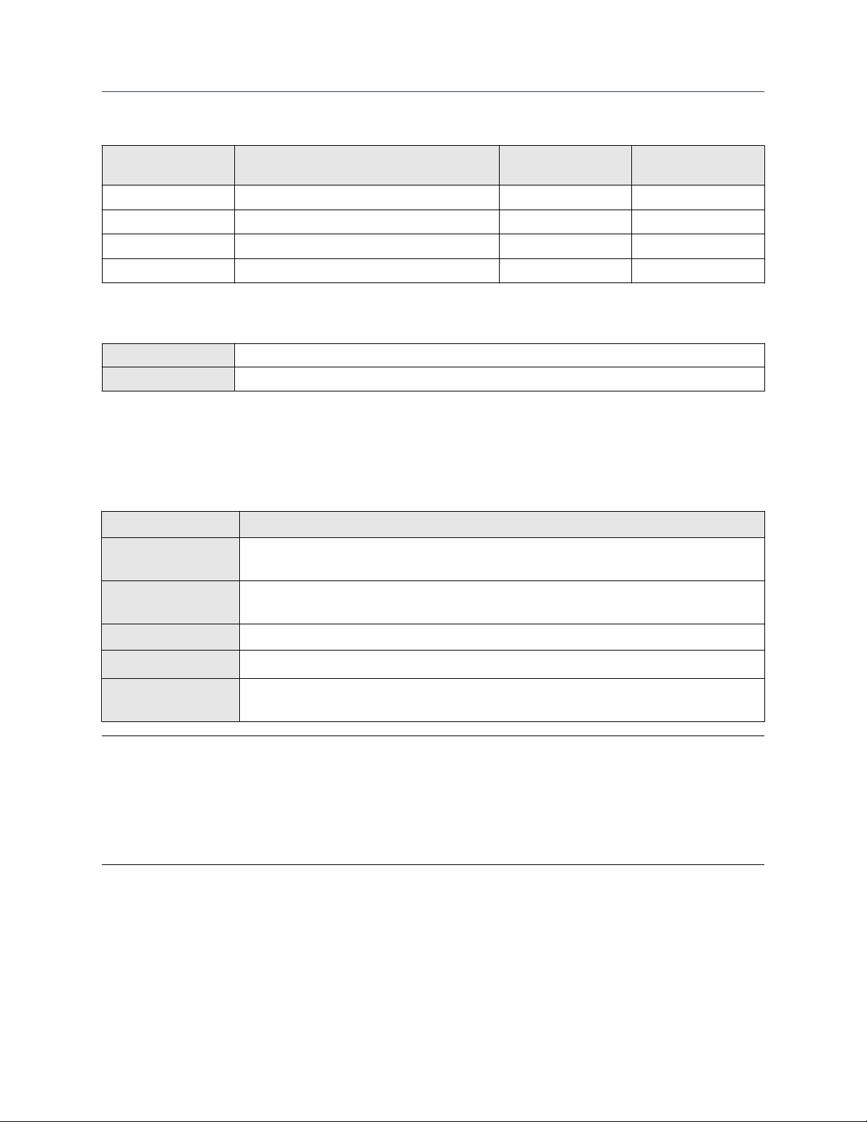
Configuration and Use Manual Configure device options and preferences
MMI-20020954 March 2021
Alert number Alert title Default severity User can reset
severity
A120 Curve Fit Failure (Concentration) Informational No
A132 Sensor Simulation Active Informational Yes
A133 EEPROM Error (Display) Informational Yes
A136 Incorrect Display Type Informational Yes
9.5 Configure informational parameters
ProLink III Device Tools → Configuration → Meter Information
Field communicator Configure → Manual Setup → Info Parameters
The informational parameters can be used to identify or describe your meter. They are not used in process
measurement and they are not required.
Procedure
Enter data as desired.
Parameter Description
Meter Serial
The serial number of the device. Enter the value from the device tag.
Number
Message
A message to be stored in device memory. The message can contain up to
32 characters.
Descriptor
Date
Flange Type
A description of this device. The description can contain up to 16 characters.
A static date (not updated by the meter). Enter the date in the form mm/dd/yyyy.
The sensor flange type for this device. Obtain the value from the documents shipped
with the device or from a code in the model number.
Tip
• A field communicator will not support all informational parameters. If you need to configure all of the
informational parameters, use ProLink III.
• A field communicator will allow you to configure HART Tag and HART Long Tag from this location. These
parameters are replicated from Configure → Manual Setup → HART → Communications. These
parameters are used in HART communications.
Configuration and Use Manual 83

Configure device options and preferences Configuration and Use Manual
March 2021 MMI-20020954
84 Micro Motion Gas Specific Gravity Meters (SGM)

Configuration and Use Manual Integrate the meter with the control system
MMI-20020954 March 2021
10 Integrate the meter with the control system
10.1 Configure Channel B
ProLink III Device Tools → Configuration → I/O → Channels
Field communicator Configure → Manual Setup → Inputs/Outputs → Channels → Channel B
Depending on your device, you can configure Channel B to operate as either an mA output or a discrete
output.
Prerequisites
The configuration of Channel B must match the wiring. See the installation manual for your device.
To avoid causing process errors:
• Configure Channel B before configuring the mA output or discrete output.
• Before changing the channel configuration, ensure that all control loops affected by the channel are under
manual control.
Restriction
You cannot configure Channel B on the following devices: SGM TPS or SGM Fixed. On these devices, Channel B
always operates as a TPS output.
Procedure
Set Channel B as desired.
Option
mA output Channel B will operate as the secondary mA Output.
Discrete output Channel B will operate as a discrete output.
Description
10.2 Configure the mA Output
The mA Output is used to report the configured process variable. The mA Output parameters control how the
process variable is reported.
The SGM mA device has two mA Outputs: Channel A and Channel B. Both outputs are fully configurable.
The SGM DO device has one mA Output: Channel A. The output is fully configurable.
The SGM TPS device has one mA Output: Channel A. The output is fully configurable.
The SGM Fixed device has one mA Output: Channel A. The output is not configurable.
Configuration and Use Manual 85
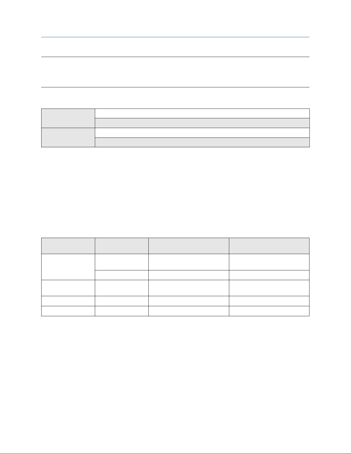
Integrate the meter with the control system Configuration and Use Manual
March 2021 MMI-20020954
Important
Whenever you change an mA output parameter, verify all other mA Output parameters before returning the
meter to service. In some situations, the transmitter automatically loads a set of stored values, and these
values may not be appropriate for your application.
10.2.1 Configure mA Output Process Variable
ProLink III Device Tools → Configuration → I/O → Outputs → mA Output → mA Output 1 → Source
Device Tools → Configuration → I/O → Outputs → mA Output → mA Output 2 → Source
Field communicator Configure → Manual Setup → Inputs/Outputs → mA Output 1 → Primary Variable
Configure → Manual Setup → Inputs/Outputs → mA Output 2 → Secondary Variable
Use mA Output Process Variable to select the variable that is reported over the mA Output.
Prerequisites
If you are using the HART variables, be aware that changing the configuration of mA Output Process Variable
will change the configuration of the HART Primary Variable (PV) and/or the HART Secondary Variable (SV).
Procedure
Set mA Output Process Variable as desired.
Default settings are shown in the following table.
Table 10-1: Default settings for
Device Channel mA Output Default process variable
SGM mA Channel A Primary mA Output Specific gravity, relative density, or
Channel B Secondary mA Output Temperature
SGM DO Channel A Primary mA Output Specific gravity, relative density, or
SGM TPS Channel A Primary mA Output Temperature
SGM Fixed Channel A Primary mA Output Temperature
(1) Not configurable.
mA Output Process Variable
assignment
molecular weight
molecular weight
(1)
Postrequisites
If you changed the setting of mA Output Process Variable, verify the settings of Lower Range Value (LRV)
and Upper Range Value (URV).
86 Micro Motion Gas Specific Gravity Meters (SGM)

Configuration and Use Manual Integrate the meter with the control system
MMI-20020954 March 2021
Options for mA Output Process Variable
The transmitter provides a basic set of options for mA Output Process Variable, plus several applicationspecific options. Different communications tools may use different labels for the options.
Process variable Label
Display ProLink III Field communicator
Standard
Line Density DENS Line Density Density
Sample Temperature TEMP Sample Temperature Temperature
Line Temperature (External
or Fixed)
Line Pressure (External or
Fixed)
Volume Flow Rate (External) MAG V Volume Flow Rate (External) Volume from Mag/Vortex
Mass Flow Rate (Calculated) MAG M Mass Flow Rate (Calculated) Calculated Mass Flow from
Mass Flow Rate (External) COR M Mass Flow Rate (External) Mass from Coriolis Meter
Volume Flow Rate
(Calculated)
Drive Gain DGAIN Drive Gain Drive Gain
Sensor Time Period TP B Sensor Time Period Sensor Time Period
User-Defined Calculation
Output
Concentration measurement
Concentration CONC Concentration Concentration (CM)
Net Mass Flow Rate NET M Net Mass Flow Rate Net Mass Flow Rate (CM)
Net Volume Flow Rate NET V Net Volume Flow Rate Net Volume Flow Rate (CM)
Gas measurement
EXT T Line Temperature (External
or Fixed)
EXT P Line Pressure (External or
Fixed)
COR V Volume Flow Rate
(Calculated)
UCALC User-Defined Calculation
Output
External Temperature
External Pressure
Meter
Mag Meter Input
Volume Flow at Reference
Temperature
User-Defined Calculation
Output
Base Density BDENS Base Density (Gas) Base Density (Gas)
Specific Gravity SG Specific Gravity (Gas) Specific Gravity (Gas)
Relative Density RD Relative Density (Gas) Relative Density
Molecular Weight MW Molecular Weight (Gas) Molecular Weight
%CO
2
%H
2
%N
2
%CO CO %CO Percent CO
Energy measurement
Calorific Value CV Calorific Value Calorific Value
Configuration and Use Manual 87
CO2 %CO2 Percent CO2
N2 %H2 Percent H2
H2 %N2 Percent N2

Integrate the meter with the control system Configuration and Use Manual
March 2021 MMI-20020954
Process variable Label
Display ProLink III Field communicator
Wobbe Index WOBBE Wobbe Index Wobbe Index
Energy Flow ENRGY Energy Flow Energy Flow
10.2.2 Configure Lower Range Value (LRV) and Upper Range Value
(URV)
ProLink III Device Tools → Configuration → I/O → Outputs → mA Output → mA Output 1 → Lower Range Value
Device Tools → Configuration → I/O → Outputs → mA Output → mA Output 1 → Upper Range Value
Device Tools → Configuration → I/O → Outputs → mA Output → mA Output 2 → Lower Range Value
Device Tools → Configuration → I/O → Outputs → mA Output → mA Output 2 → Upper Range Value
Field communicator Configure → Manual Setup → Inputs/Outputs → mA Output 1 → mA Output Settings → PV LRV
Configure → Manual Setup → Inputs/Outputs → mA Output 1 → mA Output Settings → PV URV
Configure → Manual Setup → Inputs/Outputs → mA Output 2 → mA Output Settings → SV LRV
Configure → Manual Setup → Inputs/Outputs → mA Output 2 → mA Output Settings → SV URV
The Lower Range Value (LRV) and Upper Range Value (URV) are used to scale the mA Output, that is, to
define the relationship between mA Output Process Variable and the mA Output level.
Prerequisites
Ensure that mA Output Process Variable is set to the desired process variable. Each process variable has its
own set of LRV and URV values. When you change the values of LRV and URV, you are configuring values for
the currently assigned mA Output process variable.
Ensure that the measurement unit for the configured process variable has been set as desired.
Procedure
Set LRV and URV as desired.
• LRV is the value of mA Output Process Variable represented by an output of 4 mA. The default value for
LRV depends on the setting of mA Output Process Variable. Enter LRV in the measurement units that are
configured for mA Output Process Variable.
• URV is the value of mA Output Process Variable represented by an output of 20 mA. The default value for
URV depends on the setting of mA Output Process Variable. Enter URV in the measurement units that are
configured for mA Output Process Variable.
Tip
For best performance:
• Set LRV ≥ LSL (lower sensor limit).
• Set URV ≤ USL (upper sensor limit).
• Set these values so that the difference between URV and LRV is ≥ Min Span (minimum span).
Defining URV and LRV within the recommended values for Min Span, LSL, and USL ensures that the resolution
of the mA Output signal is within the range of the bit precision of the D/A converter.
88 Micro Motion Gas Specific Gravity Meters (SGM)
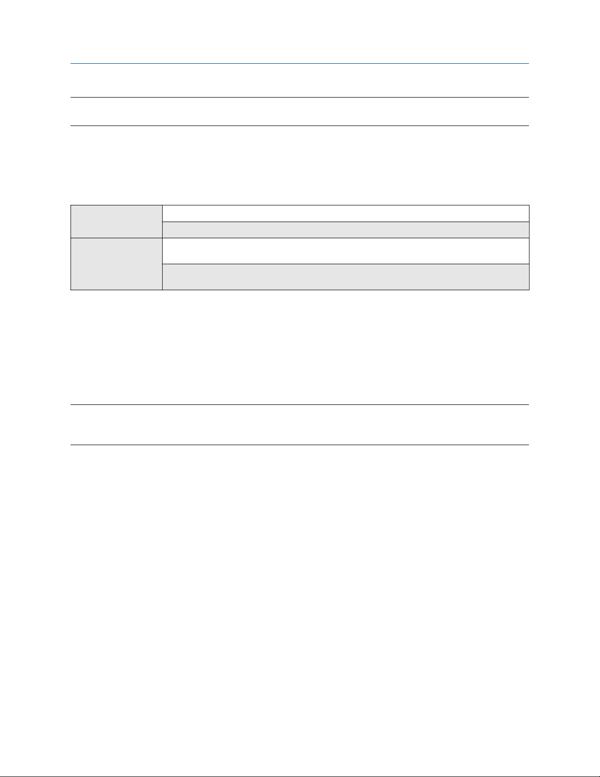
Configuration and Use Manual Integrate the meter with the control system
MMI-20020954 March 2021
Note
You can set URV below LRV. For example, you can set URV to 50 and LRV to 100.
The mA Output uses a range of 4–20 mA to represent mA Output Process Variable. Between LRV and URV,
the mA Output is linear with the process variable. If the process variable drops below LRV or rises above URV,
the transmitter posts an output saturation alert.
10.2.3 Configure Added Damping
ProLink III Device Tools → Configuration → I/O → Outputs → mA Output → mA Output 1 → Added Damping
Device Tools → Configuration → I/O → Outputs → mA Output → mA Output 2 → Added Damping
Field communicator Configure → Manual Setup → Inputs/Outputs → mA Output 1 → mA Output Settings → PV Added
Added Damping controls the amount of damping that will be applied to the mA output.
Damping is used to smooth out small, rapid fluctuations in process measurement. Damping Value specifies
the time period (in seconds) over which the transmitter will spread changes in the process variable. At the end
of the interval, the internal value will reflect 63% of the change in the actual measured value.
Damping
Configure → Manual Setup → Inputs/Outputs → mA Output 2 → mA Output Settings → SV Added
Damping
Added Damping affects the reporting of mA Output Process Variable through the mA output only. It does
not affect the reporting of that process variable via any other method (e.g., a frequency output or digital
communications), or the value of the process variable used in calculations.
Note
Added Damping is not applied if the mA output is fixed (for example, during loop testing) or if the mA output
is reporting a fault. Added Damping is applied while sensor simulation is active.
Procedure
Set Added Damping to the desired value.
The default value is 0.0 seconds. The range is 0.0 to 440 seconds.
When you specify a value for Added Damping, the transmitter automatically rounds the value down to the
nearest valid value.
Interaction between mA Output Damping and process variable damping
When mA Output Process Variable is set to one of the primary process variables (specific gravity, molecular
weight, or relative density), or to temperature, Added Damping interacts with Density Damping or
Temperature Damping.
Damping interaction
Configuration:
• mA Output Process Variable = Specific Gravity (Gas)
• Density Damping = 1 second
• Added Damping = 2 seconds
Configuration and Use Manual 89

Integrate the meter with the control system Configuration and Use Manual
March 2021 MMI-20020954
Result: A change in specific gravity will be reflected in the mA output over a time period that is greater than
3 seconds. The exact time period is calculated by the transmitter according to internal algorithms which are
not configurable.
10.2.4 Configure mA Output Fault Action and mA Output Fault
Level
ProLink III Device Tools → Configuration → I/O → Outputs → mA Output → mA Output 1 → Fault Action
Device Tools → Configuration → I/O → Outputs → mA Output → mA Output 2 → Fault Action
Field communicator Configure → Manual Setup → Inputs/Outputs → mA Output 1 → mAO1 Fault Settings → MAO1 Fault
mA Output Fault Action controls the behavior of the mA output if the transmitter encounters an internal
fault condition.
Note
For some faults only: If Fault Timeout is set to a non-zero value, the transmitter will not implement the fault
action until the timeout has elapsed.
Action
Configure → Manual Setup → Inputs/Outputs → mA Output 2 → MAO2 Fault Settings → MAO2 Fault
Action
Procedure
1. Set mA Output Fault Action to the desired value.
The default setting is Downscale.
Restriction
If Digital Communications Fault Action is set to NAN (not a number), you cannot set mA Output Fault
Action to None. If you try to do this, the device will not accept the configuration.
2. If you set mA Output Fault Action to Upscale or Downscale, set mA Output Fault Level as desired.
Postrequisites
NOTICE
If you set mA Output Fault Action to None, be sure to set Digital Communications Fault Action to None. If
you do not, the output will not report actual process data, and this may result in measurement errors or
unintended consequences for your process.
Options for mA Output Fault Action and mA Output Fault Level
Option
Upscale Goes to the configured fault level Default: 21.5 mA
Downscale (default) Goes to the configured fault level Default: 3.2 mA
mA Output behavior
mA Output Fault Level
Range: 21.0 to 21.5 mA
Range: 3.2 to 3.6 mA
90 Micro Motion Gas Specific Gravity Meters (SGM)

Configuration and Use Manual Integrate the meter with the control system
MMI-20020954 March 2021
Option mA Output behavior
Internal Zero Goes to the mA Output level associated with a
process variable value of 0 (zero), as determined
by Lower Range Value and Upper Range Value
settings
None Tracks data for the assigned process variable; no
fault action
mA Output Fault Level
Not applicable
Not applicable
10.3 Configure the Discrete Output
The Discrete Output is used to report specific meter or process conditions. The Discrete Output parameters
control which condition is reported and how it is reported. Depending on your purchase option, your
transmitter may have one Discrete Output or no Discrete Outputs.
Important
Whenever you change a Discrete Output parameter, verify all other Discrete Output parameters before
returning the meter to service. In some situations, the transmitter automatically loads a set of stored values,
and these values may not be appropriate for your application.
10.3.1 Configure Discrete Output Source
ProLink III Device Tools → Configuration → I/O → Outputs → Discrete Output
Field communicator Configure → Manual Setup → Inputs/Outputs → Discrete Output → DO Source
Discrete Output Source controls which device condition or process condition is reported via the Discrete
Output.
Procedure
Set Discrete Output Source to the desired option.
The default setting for Discrete Output Source is Fault.
Options for Discrete Output Source
Option
ProLink III Field communicator
Enhanced Event 1–5 Enhanced Event 1
Enhanced Event 2
Enhanced Event 3
Enhanced Event 4
Enhanced Event 5
Calibration in Progress Calibration in Progress Calibration in Progress ON Site-specific
Fault (default) Fault Indicator Fault ON Site-specific
Label State Discrete Output
voltage
Enhanced Event 1
Enhanced Event 2
Enhanced Event 3
Enhanced Event 4
Enhanced Event 5
ON Site-specific
OFF 0 V
OFF 0 V
OFF 0 V
Configuration and Use Manual 91

Integrate the meter with the control system Configuration and Use Manual
March 2021 MMI-20020954
Important
This table assumes that Discrete Output Polarity is set to Active High. If Discrete Output Polarity is set to
Active Low, reverse the voltage values.
10.3.2 Configure Discrete Output Polarity
ProLink III Device Tools → Configuration → I/O → Outputs → Discrete Output
Field communicator Configure → Manual Setup → Inputs/Outputs → Discrete Output → DO Polarity
Discrete outputs have two states: ON (active) and OFF (inactive). Two different voltage levels are used to
represent these states. Discrete Output Polarity controls which voltage level represents which state.
Procedure
Set Discrete Output Polarity as desired.
The default setting is Active High.
Options for Discrete Output Polarity
Polarity Description
Active High • When asserted (condition tied to DO is true), the circuit draws as
much current as it can, up to a maximum of 10 mA.
• When not asserted (condition tied to DO is false), the circuit draws
less than 1 mA.
Active Low • When asserted (condition tied to DO is true), the circuit draws less
than 1 mA.
• When not asserted (condition tied to DO is false), the circuit draws
as much current as it can, up to a maximum of 10 mA.
10.3.3 Configure Discrete Output Fault Action
ProLink III
Field communicator Configure → Manual Setup → Inputs/Outputs → Discrete Output → DO Fault Action
Discrete Output Fault Action controls the behavior of the Discrete Output if the transmitter encounters an
internal fault condition.
Note
For some faults only: If Fault Timeout is set to a non-zero value, the transmitter will not implement the fault
action until the timeout has elapsed.
Device Tools → Configuration → Fault Processing
CAUTION
Do not use Discrete Output Fault Action as a fault indicator. If you do, you may not be able to distinguish a
fault condition from a normal operating condition. If you want to use the Discrete Output as a fault
indicator, set Discrete Output Source to Fault and set Discrete Output Fault Action to None.
92 Micro Motion Gas Specific Gravity Meters (SGM)

Configuration and Use Manual Integrate the meter with the control system
MMI-20020954 March 2021
Procedure
Set Discrete Output Fault Action as desired.
The default setting is None.
Options for Discrete Output Fault Action
Discrete Output behavior
Label
Upscale • Fault: Discrete Output is ON (site-
Downscale • Fault: Discrete Output is OFF (0 V)
None (default) Discrete Output is controlled by its assignment
Polarity=Active High Polarity=Active Low
• Fault: Discrete Output is OFF (0 V)
specific voltage)
• No fault: Discrete Output is controlled
by its assignment
• No fault: Discrete Output is controlled
by its assignment
• No fault: Discrete Output is controlled
by its assignment
• Fault: Discrete Output is ON (site-
specific voltage)
• No fault: Discrete Output is controlled
by its assignment
Fault indication with the Discrete Output
To indicate faults via the Discrete Output, set Discrete Output Source to Fault. Then, if a fault occurs, the
Discrete Output is always ON and the setting of Discrete Output Fault Action is ignored.
10.4 Configure an enhanced event
ProLink III
Field communicator Configure → Alert Setup → Enhanced Events
Device Tools → Configuration → Events → Enhanced Events
An enhanced event is used to provide notification of process changes. An enhanced event occurs (is ON) if the
real-time value of a user-specified process variable moves above (HI) or below (LO) a user-defined setpoint, or
in range (IN) or out of range (OUT) with respect to two user-defined setpoints. You can define up to five
enhanced events.
Procedure
1. Select the event that you want to configure.
2. Specify Event Type.
Option
Description
HI x > A
The event occurs when the value of the assigned process variable (x) is greater
than the setpoint (Setpoint A), endpoint not included.
LO x < A
Configuration and Use Manual 93

Integrate the meter with the control system Configuration and Use Manual
March 2021 MMI-20020954
Option Description
The event occurs when the value of the assigned process variable (x) is less than
the setpoint (Setpoint A), endpoint not included.
IN A ≤ x ≤ B
The event occurs when the value of the assigned process variable (x) is in range,
that is, between Setpoint A and Setpoint B, endpoints included.
OUT x ≤ A or x ≥ B
The event occurs when the value of the assigned process variable (x) is out of
range, that is, less than Setpoint A or greater than Setpoint B, endpoints
included.
3. Assign a process variable to the event.
4. Set values for the required setpoints.
• For HI and LO events, set Setpoint A.
• For IN and OUT events, set Setpoint A and Setpoint B.
5. Optional: Configure a Discrete Output to switch states in response to the event status.
Related information
Configure Discrete Output Source
10.5 Configure HART/Bell 202 communications
HART/Bell 202 communications parameters support HART communications with the transmitter's primary
mA terminals over a HART/Bell 202 network.
10.5.1 Configure basic HART parameters
ProLink III
Field communicator Configure → Manual Setup → HART → Communications
Basic HART parameters include the HART address, HART tags, and the operation of the primary mA output.
Restriction
• Your device supports HART 7. If you are using HART 5, HART Long Tag is not available.
• HART Tag, HART Long Tag, and mA Output Action are not configurable from the display.
Device Tools → Configuration → Meter Information
Device Tools → Configuration → Communications → Communications (HART)
Procedure
1. Set HART Address to a unique value on your network.
Valid address values are between 0 and 15. The default address (0) is typically used unless you are in a
multidrop environment.
94 Micro Motion Gas Specific Gravity Meters (SGM)

Configuration and Use Manual Integrate the meter with the control system
MMI-20020954 March 2021
Tip
Devices using HART protocol to communicate with the transmitter may use either HART Address or
HART Tag (Software Tag) to identify the transmitter. Configure either or both, as required by your
other HART devices.
2. Set HART Long Tag to a unique value on your network.
3. Ensure that mA Output Action is configured appropriately.
Option Description
Enabled (Live) The primary mA Output reports process data as configured. This is the
appropriate setting for most applications.
Disabled (Fixed) The primary mA Output is fixed at 4 mA and does not report process data.
Important
If you use ProLink III to set HART Address to 0, the program automatically enables mA Output Action.
If you use ProLink III to set HART Address to any other value, the program automatically disables mA
Output Action. This is designed to make it easier to configure the transmitter for legacy behavior.
Always verify mA Output Action after setting HART Address.
10.5.2 Configure HART variables (PV, SV, TV, QV)
ProLink III
Field communicator Configure → Manual Setup → Inputs/Outputs → Variable Mapping
The HART variables are a set of four variables predefined for HART use. The HART variables include the
Primary Variable (PV), Secondary Variable (SV), Tertiary Variable (TV), and Quaternary Variable (QV). You can
assign specific process variables to the HART variables, and then use standard HART methods to read or
broadcast the assigned process data.
Tip
The Tertiary Variable and Quaternary Variable are also called the Third Variable (TV) and Fourth Variable (FV).
Restriction
On some devices, the PV is fixed to a specific process variable and cannot be changed.
Options for HART variables
Process variable
Standard
Line Density ✓ ✓ ✓ ✓
Sample Temperature ✓ ✓ ✓ ✓
Device Tools → Configuration → Communications → Communications (HART)
Primary
Variable (PV)
Secondary
Variable (SV)
Third Variable
(TV)
Fourth
Variable (QV )
Sample Temperature (External or Fixed) ✓ ✓ ✓ ✓
Line Pressure (External or Fixed) ✓ ✓ ✓ ✓
Configuration and Use Manual 95

Integrate the meter with the control system Configuration and Use Manual
March 2021 MMI-20020954
Process variable Primary
Variable (PV)
Volume Flow Rate (External) ✓ ✓ ✓ ✓
Volume Flow Rate (Calculated) ✓ ✓ ✓ ✓
Mass Flow Rate (External) ✓ ✓ ✓ ✓
Mass Flow Rate (Calculated) ✓ ✓ ✓ ✓
Drive Gain ✓ ✓ ✓ ✓
Sensor Time Period ✓ ✓ ✓ ✓
User-Defined Calculation Output ✓ ✓ ✓ ✓
Board Temperature ✓ ✓
Input Voltage ✓ ✓
Concentration
Concentration ✓ ✓ ✓ ✓
Net Mass Flow Rate ✓ ✓ ✓ ✓
Net Volume Flow Rate ✓ ✓ ✓ ✓
Gas measurement
Base Density (Gas) ✓ ✓ ✓ ✓
Specific Gravity (Gas) ✓ ✓ ✓ ✓
Secondary
Variable (SV)
Third Variable
(TV)
Fourth
Variable (QV )
Relative Density (Gas) ✓ ✓ ✓ ✓
Molecular Weight (Gas) ✓ ✓ ✓ ✓
Compressibility ✓ ✓
%CO
2
%H
2
%N
2
%CO ✓ ✓ ✓ ✓
Energy measurement
Calorific Value ✓ ✓ ✓ ✓
Wobbe Index ✓ ✓ ✓ ✓
Energy Flow ✓ ✓ ✓ ✓
✓ ✓ ✓ ✓
✓ ✓ ✓ ✓
✓ ✓ ✓ ✓
Interaction of HART variables and transmitter outputs
The HART variables are automatically reported through specific transmitter outputs. They may also be
reported through HART burst mode, if enabled on your transmitter.
Restriction
One some devices, the PV and the primary mA output are fixed to a specific process variable and cannot be
changed.
96 Micro Motion Gas Specific Gravity Meters (SGM)

Configuration and Use Manual Integrate the meter with the control system
MMI-20020954 March 2021
Table 10-2: HART variables and transmitter outputs
HART variable Reported via Comments
Primary Variable (PV) Primary mA Output If one assignment is changed, the other is changed
automatically, and vice versa.
Secondary Variable (SV) Secondary mA Output, if
present on your transmitter
Tertiary Variable (TV) Not associated with an
output
Quaternary Variable (QV) Not associated with an
output
If you have a secondary mA output: If one assignment is
changed, the other is changed automatically.
If you do not have a secondary mA output: The SV must be
configured directly, and the value of the SV is available only
via digital communications.
The TV must be configured directly, and the value of the TV
is available only via digital communications.
The QV must be configured directly, and the value of the
QV is available only via digital communications.
10.5.3 Configure burst communications
Burst mode is a mode of communication during which the transmitter regularly broadcasts HART digital
information to the network via the primary mA Output.
Restriction
Burst communications, including trigger mode and event notification, are not available on HART/RS-485.
These features are supported only on HART/Bell 202.
Configure HART burst messages
ProLink III
Field communicator Configure → Manual Setup → HART → Burst Mode
Device Tools → Configuration → Communications → Communications (HART)
Burst messages contain information on process variables or transmitter status. You can configure up to three
burst messages. Each message can contain different information. Burst messages also provide the
mechanism for trigger mode and event notification.
Restriction
If you are using a HART 5 host, only one burst message is supported.
Procedure
1. Navigate to the burst message you want to configure.
2. Enable the burst message.
3. Set Burst Option to the desired content.
Table 10-3: Options for burst message contents
HART
command
1 Source (Primary
Configuration and Use Manual 97
ProLink III Field communicator
Variable)
Label Description
Primary Variable The transmitter sends the primary variable (PV) in
the configured measurement units in each burst
message (e.g., 14.0 g/sec, 13.5 g/sec, 12.0 g/sec).
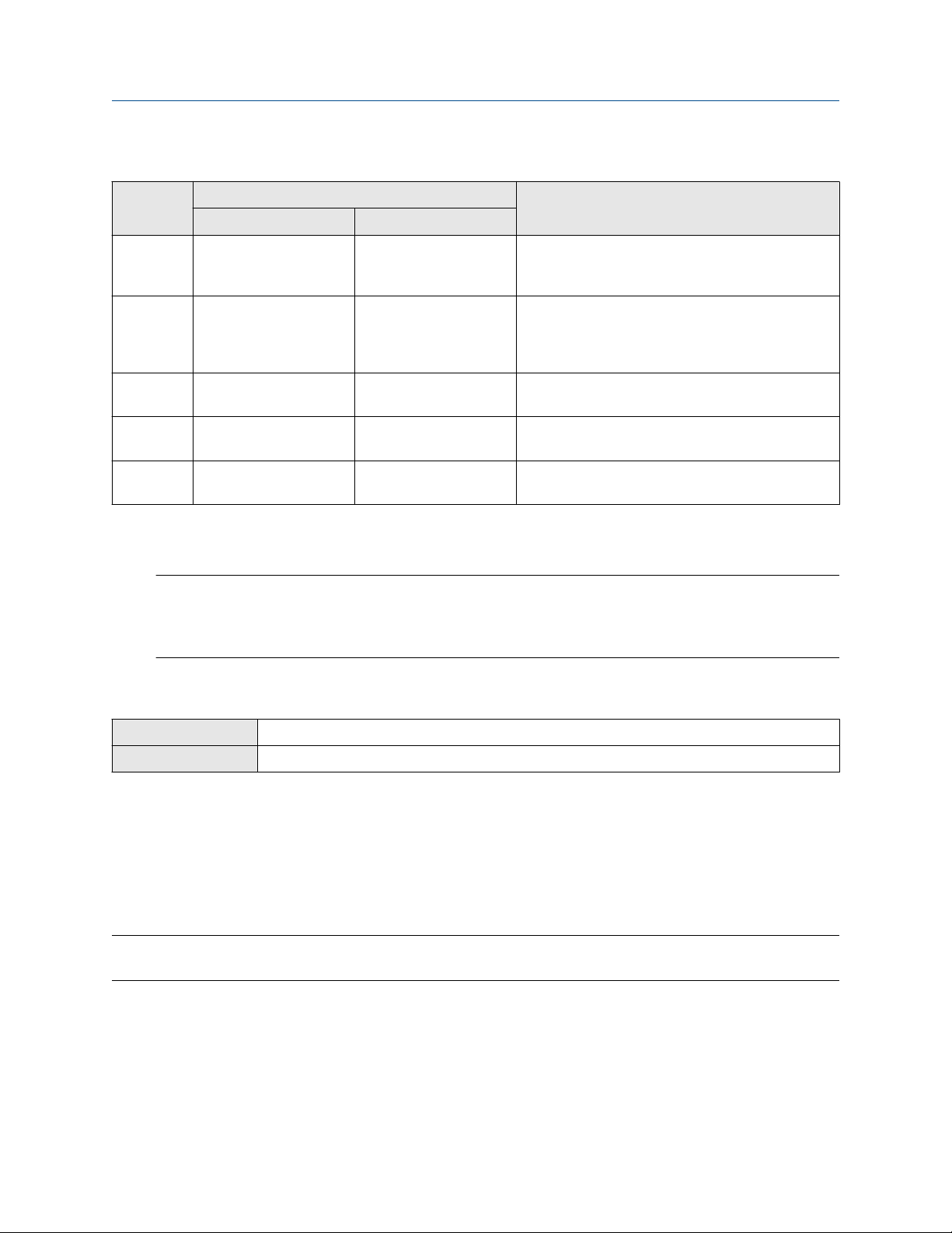
Integrate the meter with the control system Configuration and Use Manual
March 2021 MMI-20020954
Table 10-3: Options for burst message contents (continued)
HART
command
2 Primary Variable
3 Process Variables/
9 Read Device Variables
33 Transmitter Variables Field Device Vars The transmitter sends four user-specified process
48 Read Additional
ProLink III Field communicator
(Percent Range/Current)
Current
with Status
Transmitter Status
Label Description
Pct Range/Current The transmitter sends the PV’s actual mA level and
the PV’s percent of range in each burst message
(e.g.,11.0 mA 25%).
Process Vars/Current The transmitter sends the PV’s actual milliamp
reading and the PV, SV, TV, and QV values in
measurement units in each burst message (e.g.,
11.8 mA, 50 g/sec, 23 °C, 50 g/sec, 0.0023 g/cm3).
Device Variables with
Status
Read Additional Device
Status
The transmitter sends up to eight user-specified
process variables in each burst message.
variables in each burst message.
The transmitter sends expanded device status
information in each burst message.
4. Depending on your choice, select the four or eight user-specified variables for the burst message, or
set the HART variables as desired.
Important
If you change the HART Primary Variable (PV) or Secondary Variable (SV), the process variables
assigned to the primary mA Output and the secondary mA Output (if applicable) are automatically
changed to match. The PV cannot be changed on devices with fixed mA Output assignments.
Configure HART trigger mode
ProLink III
Field communicator Configure → Manual Setup → HART → Burst Mode → Burst Message x → Configure Update Rate
Trigger mode uses the burst message mechanism to indicate that a process variable has changed. When
trigger mode is implemented, the bursting interval (HART update rate) changes if Primary Variable or
Burst Variable 0 moves above or below the user-specified trigger level. You can set up a different trigger on
each burst message.
Prerequisites
Before you can configure trigger mode, the corresponding HART burst message must be enabled.
Restriction
This feature is available only with a HART 7 host.
Procedure
1. Select the burst message for which you will set up trigger mode.
2. Set Trigger Mode to the type of trigger you want to use.
Device Tools → Configuration → Communications → Communications (HART)
98 Micro Motion Gas Specific Gravity Meters (SGM)

Configuration and Use Manual Integrate the meter with the control system
MMI-20020954 March 2021
Option Description
Continuous The burst message is sent at Default Update Rate. The burst interval is not affected by
changes in process variables.
Falling • When the specified process variable is above Trigger Level, the burst message is sent
at Default Update Rate.
• When the specified process variable is below Trigger Level, the burst message is sent
at Update Rate.
Rising • When the specified process variable is below Trigger Level, the burst message is sent
at Default Update Rate.
• When the specified process variable is above Trigger Level, the burst message is sent
at Update Rate.
Windowed This option is used to communicate that the process variable is changing rapidly.
Trigger Level defines a deadband around the most recently broadcast value.
• If the process variable stays within this deadband, the burst message is sent at
Default Update Rate.
• If the process variable moves outside this deadband in either direction, the burst
message is sent at Update Rate.
On Change • If any value in the burst message changes, the burst message is sent at Update Rate.
• If no values change, the burst message is sent at Default Update Rate.
3. Ensure that Primary Variable or Burst Variable 0 is set to the variable that will activate the trigger. If it
is not, reconfigure the burst message contents.
4. Set Trigger Level to the value of the process variable at which the trigger will be activated.
5. Set Default Update Rate to the burst interval to be used when the trigger is not active.
6. Set Update Rate to the burst interval to be used when the trigger is active.
Configure HART event notification
ProLink III
Field communicator Configure → Manual Setup → HART → Event Notification
Event notification uses the burst message mechanism to indicate that an alert has occurred. When event
notification is enabled and one or more of the selected alerts occurs, each active burst message will broadcast
HART Command 119 until the condition is acknowledged by a HART master.
Prerequisites
Device Tools → Configuration → Communications → Communications (HART) → Event Notification
If you are using a field communicator, you must enable a burst message before you can configure event
notification.
Tip
Event notification affects only HART burst messages. Whether an alert is selected for event notification or not,
alert severity, alert status (active or inactive), fault timeout, and alert acknowledgment operate as normal.
Configuration and Use Manual 99

Integrate the meter with the control system Configuration and Use Manual
March 2021 MMI-20020954
Restriction
This feature is available only with a HART 7 host.
Procedure
1. Enable event notification.
2. Select all desired alerts.
If one or more of the selected alerts occurs, each active burst message will broadcast HART Command
119 until the alert is acknowledged by a HART master.
3. Set Trigger Interval as desired.
Trigger Interval controls the delay before HART Command 119 is broadcast.
• Default: 0 seconds
• Range: 0.5 to 3600 seconds
Trigger Interval begins when the transmitter detects the alert condition. When Trigger Interval
expires:
• If the alert is still active, HART Command 119 is broadcast.
• If the alert is not active, no message is broadcast.
Tip
If you set Trigger Interval to 0, HART Command 119 is broadcast as soon as the alert is detected.
4. Set Retry Rate as desired.
Retry Rate controls the rate at which HART Command 119 is broadcast when event notification is
active.
• Default: 0.5 seconds
5. Set Maximum Update Time as desired.
Maximum Update Time controls the rate at which HART Command 119 is broadcast when event
notification is not active.
• Default: 60 seconds
10.6 Configure Modbus communications
ProLink III
Field communicator Not available
Modbus communications parameters control Modbus communications with the transmitter.
Device Tools → Configuration → Communications → Communications (Modbus)
Modbus support is implemented on the RS-485 physical layer via the RS-485 terminals.
Important
Your device automatically accepts all connection requests within the following ranges:
• Protocol: Modbus RTU (8-bit) or Modbus ASCII (7-bit) unless Modbus ASCII Support is disabled
100 Micro Motion Gas Specific Gravity Meters (SGM)
 Loading...