

Wiring Supplement
P/N MMI-20015706, Rev. AA
September 2009
Micro Motion® Model 775
Smart Wireless Integral-Mount THUM™ Adapter
Contents
THUM Adapter overview . . . . . . . . . . . . . . . . . . . . . . . . . . . . . . . . . . . . . . . . . .page 3
Installation considerations . . . . . . . . . . . . . . . . . . . . . . . . . . . . . . . . . . . . . . . . .page 4
Locating the THUM Adapter . . . . . . . . . . . . . . . . . . . . . . . . . . . . . . . . . . . . . . .page 4
THUM Adapter wiring requirements. . . . . . . . . . . . . . . . . . . . . . . . . . . . . . . . . .page 5
Wiring the integral-mount THUM Adapter . . . . . . . . . . . . . . . . . . . . . . . . . . . . .page 6
Post-installation and configuration of the THUM Adapter . . . . . . . . . . . . . . . . .page 7

About this supplement
The Micro Motion
®
Model 775: Smart Wireless Integral-Mount THUM™ Adapter Wiring Supplement provides
detailed information on wiring the integral-mount THUM Adapter wireless device to your Micro Motion
meter. This supplement is not a comprehensive guide for the Smart Wireless THUM Adapter device.
For additional information on installing and configuring the Smart Wireless THUM Adapter, refer to the
Smart Wireless THUM
™
Adapter Quick Installation Guide or Smart Wireless THUM™ Adapter Reference
Manual also available on the Micro Motion Product Documentation CD or at www.micromotion.com.
For more information on installing and configuring your Micro Motion meter, see the Micro Motion Product
Documentation CD for the appropriate product manual.
Safety and approval information
This Micro Motion product complies with all applicable European directives when properly installed in
accordance with the instructions in this manual. Refer to the EC declaration of conformity for directives that
apply to this product. The EC declaration of conformity, with all applicable European directives, and the
complete ATEX Installation Drawings and Instructions are available on the internet at
www.micromotion.com/atex or through your local Micro Motion support center.
For hazardous installations in Europe, refer to standard EN60079-14 if national standards do not apply.
Micro Motion customer service
For customer service, phone the support center nearest you:
• In the U.S.A., phone
800-522-MASS (800-522-6277) (toll-free)
• In Canada and Latin America, phone +1 303-527-5200
•In Asia:
- In Japan, phone 3 5769-6803
- In other locations, phone +65 6777-8211 (Singapore)
• In Europe:
- In the U.K., phone 0870 240 1978 (toll-free)
- In other locations, phone +31 (0) 318 495 555 (The Netherlands)
Customers outside the U.S.A. can also email Micro Motion customer service at flow.support@emerson.com.
© 2009 Micro Motion, Inc. All rights reserved.
The Micro Motion and Emerson logos are trademarks and service marks of Emerson Electric Co. Micro Motion, ELITE, MVD,
ProLink, MVD Direct Connect, and PlantWeb are marks of one of the Emerson Process Management family of companies. All
other trademarks are property of their respective owners.
THUM Adapter overview
MICRO MOTION INC MIC
RO MOTI
ON INC
MODEL S/N MODEL S/
N
Smart Wireless THUM Adapter
Transmitter housing
Transmitter cover removed
Terminal block connectors
Smart Wireless
THUM Adapter
Transmitter housing
Transmitter cover removed
Terminal block
connectors
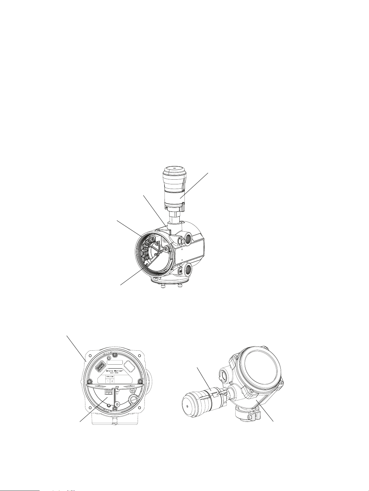
The Smart Wireless THUM™ Adapter acts as an extension of the HART function of the primary mA output
on your Micro Motion transmitter. It broadcasts HART data from the transmitter to the Wireless HART
™
network. The THUM Adapter can be used with any Micro Motion transmitter that supports HART over the
primary mA output. The Smart Wireless THUM Adapter is shipped integrally mounted to the Micro Motion
transmitter.
The THUM Adapter is installed using an approved thread sealant and secured to a torque value of 30–35
ft-lbs. Figure 1 shows an integrally mounted THUM adapter installed in a Model 2700 transmitter. Figure 2
shows an integrally mounted THUM adapter installed in a Model 2200S transmitter.
Figure 1 Integral-mount THUM Adapter components (Model 2700)
Figure 2 Integral-mount THUM Adapter components (Model 2200S)
Micro Motion Model 775 Wiring Supplement 3

Installation considerations
Explosions could result in death or serious injury.
Installation of the equipment in an explosive environment must be in accordance with the appropriate
local, national, and international standards, codes, and practices. Please review the Product Certifications
section in the Smart Wireless THUM
with a safe installation.
Before connecting a Communicator in an explosive atmosphere, ensure the instruments are installed in
accordance with intrinsically safe or non-incendive field wiring practices.
Electrical shock can result in death or serious injury.
Avoid contact with the leads and terminals. High voltage that may be present on leads can cause electrical
shock.This device complies with Part 15 of the FCC Rules. Operation is subject to the following conditions. This device may not cause harmful interference.
Do not install the THUM Adapter or all other wireless devices until the Smart Wireless Gateway has been
installed and is functioning properly. Power up the wireless devices in the order of proximity from the
Smart Wireless Gateway, beginning with the closest. This will result in a simpler and faster network installation. For more information, see the Smart Wireless Gateway Manual available on the Micro Motion product documentation CD or at www.micromotion.com
™
Adapter Quick Installation Guide for any restrictions associated
Locating the THUM Adapter
For best performance, the THUM Adapter should be installed according to the following requirements:
• Access to the device
• Optimally, in a vertical position – either straight up or straight down
• With approximately 3 ft (1 m) between objects in a parallel metal plane such as a pipe or metal
framework. Pipes or framework may adversely affect the performance of the antenna.
This device must be installed to ensure a minimum antenna separation distance of 7.9" (20 cm) from all
persons. This device must accept any interference received, including interference that may cause undesired operation.
4 Micro Motion Model 775 Wiring Supplement

THUM Adapter wiring requirements
The THUM Adapter must be wired to the transmitter’s primary mA output. Wiring depends on whether the
mA output is internally powered (active) or externally powered (passive). Adapt the wiring diagrams in the
transmitter installation manual as required.
The THUM Adapter causes a voltage drop across the loop. The drop is linear from 2.25 V at 3.5 mA to 1.2 V
at 25 mA, but does not effect the 4–20 mA signal on the loop. Under fault conditions, the maximum voltage
drop is 2.5 V. To maintain normal operating functions of the wired device, the power in the loop must have at
least a 2.5 V margin at a 250 Ohm load.
Ensure that the power supply can provide at least 2.5 V more than the lift-off voltage of the meter to make
sure it works properly with the THUM Adapter installation. During normal operation, or in fault condition,
the THUM Adapter will cause a 2.5 V drop in the connected loop. To determine the lift-off voltage for the
meter, refer to the meter installation and configuration manual.
Additional wiring requirements for hazardous area installations
For hazardous area installations, you may be required to use either cable glands or conduit to wire between the
THUM Adapter and the transmitter.
• If you use cable glands:
- You must supply the appropriate cable glands. Cable glands are available from Micro Motion.
- For best results, use shielded or armored cable.
• If you use conduit, any poured seals must be within 18" (45.7 cm) of the transmitter conduit opening.
Micro Motion Model 775 Wiring Supplement 5

Wiring the integral-mount THUM Adapter
Ensure that your installation complies with all applicable safety requirements. Refer to the
transmitter installation manual for additional safety information.
1. Power down the transmitter. WARNING! If the transmitter is in a hazardous area, wait five minutes
before opening the wiring compartment.
2. Access the wiring compartment on the transmitter.
3. Connect the wires from the THUM Adapter to the transmitter terminals as shown in Table 1.
Figure 3 identifies the terminal block connectors. The following information applies to all installations.
Table 1 Integral-mount THUM Adapter wiring to transmitter
Primary
mA output
For
internally
powered
(active)
For
externally
powered
(passive)
(1) If your installation does not include mA output wiring, create a loop by connecting both wires
to a 250crimp or pinch the wires or interfere with other wiring.
THUM Adapter
wire At transmitter
Red wire mA + terminal on transmitter
Black wire mA – terminal on transmitter
Yellow wire Splice into the mA output wiring
White wire Splice into mA output wiring
Yellow wire mA + terminal on transmitter
White wire mA – terminal on transmitter
Red wire Splice into mA output wiring
Black wire Splice into mA output wiring
Green wire Transmitter internal ground
For the 2200S, a redundant ground is provided
with a green wire attached to the internal housing
ground screw.
Ω
resistor. When you close the wiring compartment, tuck the resistor inside. Do not
(1)
(1)
(1)
(1)
6 Micro Motion Model 775 Wiring Supplement

Figure 3 Transmitter terminal block connections
mA +
mA –
Warning flap
Ground
mA +
mA –
2700 terminal connections
2200S terminal connections
4. Close the wiring compartment and replace all covers.
5. Reinstall the conduit or cable gland.
Post-installation and configuration of the THUM Adapter
For information on verifying your THUM Adapter installation, refer to the Smart Wireless THUM™ Adapter
Quick Installation Guide.
For information on configuring and troubleshooting the wireless device, refer to the Smart Wireless THUM
Adapter Reference Manual. Both manuals are available on the Micro Motion Product Documentation CD or at
www.micromotion.com.
™
Micro Motion Model 775 Wiring Supplement 7

Micro Motion Inc. USA
Worldwide Headquarters
7070 Winchester Circle
Boulder, Colorado 80301
T +1 303-527-5200
+1 800-522-6277
F +1 303-530-8459
Micro Motion Europe
Emerson Process Management
Neonstraat 1
6718 WX Ede
The Netherlands
T +31 (0) 318 495 555
F +31 (0) 318 495 556
Micro Motion Japan
Emerson Process Management
1-2-5, Higashi Shinagawa
Shinagawa-ku
Tokyo 140-0002 Japan
T +81 3 5769-6803
F +81 3 5769-6844
Micro Motion Asia
Emerson Process Management
1 Pandan Crescent
Singapore 128461
Republic of Singapore
T +65 6777-8211
F +65 6770-8003
Micro Motion United Kingdom
Emerson Process Management Limited
Horsfield Way
Bredbury Industrial Estate
Stockport SK6 2SU U.K.
T +44 0870 240 1978
F +44 0800 966 181
© 2009 Micro Motion, Inc. All rights reserved. P/N MMI-20015706, Rev. AA
*MMI-20015706*
For the latest Micro Motion product specifications, view the
PRODUCTS section of our web site at www.micromotion.com
 Loading...