


Instruction Manual
P/N 3300992, Rev. C
November 2003
Micro Motion
®
Series 3000
Detailed Setup Manual
Micro Motion
TM


Micro Motion
®
Series 3000
Detailed Setup Manual
For online technical support, refer to the EXPERT2™ tool at
www.expert2.com. To speak to a customer service
representative, call the support center nearest you:
• In U.S.A., phone 1-800-522-MASS (1-800-522-6277)
• In Canada and Latin America, phone (303) 530-8400
• In Asia, phone (65) 6770-8155
• In the U.K., phone 0800 - 966 180 (toll-free)
• Outside the U.K., phone +31 (0) 318 495 670
©2003, Micro Motion, Inc. All rights reserved. Micro Motion is a registered trademark
of Micro Motion, Inc. The Micro Motion and Emerson logos are trademarks of
Emerson Electric Co. All other trademarks are property of their respective owners.


Contents
1 Before You Begin . . . . . . . . . . . . . . . . . . . . . . 1
1.1 About this manual . . . . . . . . . . . . . . . . . . . . . . . . . . . . . . 1
1.2 Organization. . . . . . . . . . . . . . . . . . . . . . . . . . . . . . . . . . . 1
1.1 Appendixes . . . . . . . . . . . . . . . . . . . . . . . . . . . . . . . . . . . 2
2 Person-Process Interface . . . . . . . . . . . . . . . . . 3
2.1 About this chapter . . . . . . . . . . . . . . . . . . . . . . . . . . . . . . 3
2.2 Person-Process Interface. . . . . . . . . . . . . . . . . . . . . . . . . 3
2.3 Scientific notation . . . . . . . . . . . . . . . . . . . . . . . . . . . . . . . 6
3 System Data. . . . . . . . . . . . . . . . . . . . . . . . . . 9
3.1 About this chapter . . . . . . . . . . . . . . . . . . . . . . . . . . . . . . 9
3.2 Recording system data . . . . . . . . . . . . . . . . . . . . . . . . . . 9
3.3 System data . . . . . . . . . . . . . . . . . . . . . . . . . . . . . . . . . . 10
4 Inputs . . . . . . . . . . . . . . . . . . . . . . . . . . . . . 11
4.1 About this chapter . . . . . . . . . . . . . . . . . . . . . . . . . . . . . 11
4.2 Recording inputs . . . . . . . . . . . . . . . . . . . . . . . . . . . . . . 11
4.3 Disabling Coriolis inputs, Coriolis alarms, and
sensor alarms . . . . . . . . . . . . . . . . . . . . . . . . . . . . . . . . 13
4.4 Configure process variables. . . . . . . . . . . . . . . . . . . . . . 14
4.5 Sensor calibration data . . . . . . . . . . . . . . . . . . . . . . . . . 18
4.6 Sensor information . . . . . . . . . . . . . . . . . . . . . . . . . . . . . 26
4.7 Frequency input . . . . . . . . . . . . . . . . . . . . . . . . . . . . . . . 27
5 Discrete Batch . . . . . . . . . . . . . . . . . . . . . . . 29
5.1 About this chapter . . . . . . . . . . . . . . . . . . . . . . . . . . . . . 29
5.2 Recording discrete batch parameters . . . . . . . . . . . . . . 29
5.3 Flow source . . . . . . . . . . . . . . . . . . . . . . . . . . . . . . . . . . 31
5.4 Control options . . . . . . . . . . . . . . . . . . . . . . . . . . . . . . . . 32
5.5 Configure presets. . . . . . . . . . . . . . . . . . . . . . . . . . . . . . 34
5.6 Discrete inputs or discrete events . . . . . . . . . . . . . . . . . 37
6 Measurements . . . . . . . . . . . . . . . . . . . . . . . 39
6.1 About this chapter . . . . . . . . . . . . . . . . . . . . . . . . . . . . . 39
6.2 Recording measurement parameters . . . . . . . . . . . . . . 39
6.3 Totalizers . . . . . . . . . . . . . . . . . . . . . . . . . . . . . . . . . . . . 41
6.4 Process comparator . . . . . . . . . . . . . . . . . . . . . . . . . . . . 42
Series 3000 Detailed Setup Manual i

Contents continued
7 Outputs . . . . . . . . . . . . . . . . . . . . . . . . . . . . 47
7.1 About this chapter . . . . . . . . . . . . . . . . . . . . . . . . . . . . . 47
7.2 Recording outputs . . . . . . . . . . . . . . . . . . . . . . . . . . . . . 47
7.3 Discrete outputs. . . . . . . . . . . . . . . . . . . . . . . . . . . . . . . 49
7.4 Milliamp outputs. . . . . . . . . . . . . . . . . . . . . . . . . . . . . . . 51
7.5 Frequency output. . . . . . . . . . . . . . . . . . . . . . . . . . . . . . 53
8 Monitoring. . . . . . . . . . . . . . . . . . . . . . . . . . 55
8.1 About this chapter . . . . . . . . . . . . . . . . . . . . . . . . . . . . . 55
8.2 Recording monitoring data. . . . . . . . . . . . . . . . . . . . . . . 55
8.3 Process monitor. . . . . . . . . . . . . . . . . . . . . . . . . . . . . . . 56
9 Digital Communication . . . . . . . . . . . . . . . . . 57
9.1 About this chapter . . . . . . . . . . . . . . . . . . . . . . . . . . . . . 57
9.2 Recording printer settings . . . . . . . . . . . . . . . . . . . . . . . 57
9.3 Configuring the printer setup . . . . . . . . . . . . . . . . . . . . . 58
9.4 Weights and measures ticket. . . . . . . . . . . . . . . . . . . . . 61
9.5 Printer test . . . . . . . . . . . . . . . . . . . . . . . . . . . . . . . . . . . 62
10 Passwords and Language . . . . . . . . . . . . . . . 63
10.1 About this chapter . . . . . . . . . . . . . . . . . . . . . . . . . . . . . 63
10.2 Security . . . . . . . . . . . . . . . . . . . . . . . . . . . . . . . . . . . . . 63
10.3 Security for weights and measures . . . . . . . . . . . . . . . . 65
10.4 Language. . . . . . . . . . . . . . . . . . . . . . . . . . . . . . . . . . . . 65
11 Custody Transfer. . . . . . . . . . . . . . . . . . . . . . 67
11.1 About this chapter . . . . . . . . . . . . . . . . . . . . . . . . . . . . . 67
11.2 Custody transfer configuration procedure . . . . . . . . . . . 67
11.3 Security breach . . . . . . . . . . . . . . . . . . . . . . . . . . . . . . . 80
12 Operation Mode . . . . . . . . . . . . . . . . . . . . . . 81
12.1 About this chapter . . . . . . . . . . . . . . . . . . . . . . . . . . . . . 81
12.2 Startup and display test . . . . . . . . . . . . . . . . . . . . . . . . . 81
12.3 Sensor zero . . . . . . . . . . . . . . . . . . . . . . . . . . . . . . . . . . 81
12.4 Default operation mode . . . . . . . . . . . . . . . . . . . . . . . . . 84
12.5 Operation mode for discrete batch control. . . . . . . . . . . 85
12.6 Using the view menu . . . . . . . . . . . . . . . . . . . . . . . . . . . 90
13 Alarms . . . . . . . . . . . . . . . . . . . . . . . . . . . . 97
13.1 About this chapter . . . . . . . . . . . . . . . . . . . . . . . . . . . . . 97
13.2 Alarm messages . . . . . . . . . . . . . . . . . . . . . . . . . . . . . . 97
13.3 Active alarm log . . . . . . . . . . . . . . . . . . . . . . . . . . . . . . 110
13.4 Customer service. . . . . . . . . . . . . . . . . . . . . . . . . . . . . 110
ii Series 3000 Detailed Setup Manual

Contents continued
14 Diagnostics Menu . . . . . . . . . . . . . . . . . . . . 111
14.1 About this chapter . . . . . . . . . . . . . . . . . . . . . . . . . . . . 111
14.2 Reading inputs . . . . . . . . . . . . . . . . . . . . . . . . . . . . . . . 112
14.3 Setting outputs . . . . . . . . . . . . . . . . . . . . . . . . . . . . . . . 113
15 Active Alarm Log . . . . . . . . . . . . . . . . . . . . 115
15.1 About this chapter . . . . . . . . . . . . . . . . . . . . . . . . . . . . 115
15.2 Active alarm log . . . . . . . . . . . . . . . . . . . . . . . . . . . . . . 116
15.3 For more information about alarms . . . . . . . . . . . . . . . 116
16 Totalizers. . . . . . . . . . . . . . . . . . . . . . . . . . 117
16.1 About this chapter . . . . . . . . . . . . . . . . . . . . . . . . . . . . 117
16.2 Configuring totalizers . . . . . . . . . . . . . . . . . . . . . . . . . . 117
16.3 Batch inventory totalizers . . . . . . . . . . . . . . . . . . . . . . . 118
16.4 Process inventory totalizers . . . . . . . . . . . . . . . . . . . . . 118
17 Calibration and Trim . . . . . . . . . . . . . . . . . . 121
17.1 About this chapter . . . . . . . . . . . . . . . . . . . . . . . . . . . . 121
17.2 Necessary versus optional calibration and
trim procedures . . . . . . . . . . . . . . . . . . . . . . . . . . . . . . 121
17.3 Sensor zero . . . . . . . . . . . . . . . . . . . . . . . . . . . . . . . . . 123
17.4 Density calibration . . . . . . . . . . . . . . . . . . . . . . . . . . . . 123
17.5 Milliamp output trim . . . . . . . . . . . . . . . . . . . . . . . . . . . 130
17.6 Batch AOC . . . . . . . . . . . . . . . . . . . . . . . . . . . . . . . . . . 132
17.7 Temperature calibration . . . . . . . . . . . . . . . . . . . . . . . . 133
17.8 Viewing current data for calibrations . . . . . . . . . . . . . . 135
18 Meter Factors. . . . . . . . . . . . . . . . . . . . . . . 137
18.1 About this chapter . . . . . . . . . . . . . . . . . . . . . . . . . . . . 137
18.2 Meter factors and measurements . . . . . . . . . . . . . . . . 137
18.3 Proving factors . . . . . . . . . . . . . . . . . . . . . . . . . . . . . . . 138
18.4 Volume method . . . . . . . . . . . . . . . . . . . . . . . . . . . . . . 138
18.5 Multivariable method . . . . . . . . . . . . . . . . . . . . . . . . . . 140
18.6 Viewing current data for meter factors . . . . . . . . . . . . . 150
18.7 Resetting meter factors and proving factors. . . . . . . . . 150
Appendixes
Software Diagrams . . . . . . . . . . . . . . . . . . . . . . . . . . . . . . . . . . 151
Series 3000 Software Configuration Record. . . . . . . . . . . . . . . 159
Index . . . . . . . . . . . . . . . . . . . . . . . . . . . . . . . 169
Series 3000 Detailed Setup Manual iii

Series 3000 Detailed Setup Manual iv

1 Before You Begin
1.1 About this manual This manual explains how to use the Series 3000 software to configure,
operate, and maintain the Model 3300, 3350, 3500, and 3700
applications platforms.
This manual provides information about the following applications:
• Model 3500 or 3700 transmitter
• Discrete batch control
• Process and inventory totalizers
• Process monitor
• Process comparator
• Security for custody transfer
This manual does not provide information about the Series 3000 Net Oil
Computer or the density application.
• For information about the Net Oil Computer, see the Series 3000 Net
Oil Computer Manual.
• For information about the density application, see the Series 3000
Density Application Manual.
This manual does not explain installation or wiring. For information about
installation and wiring, see the Series 3000 Installation Manual.
Person-Process Interface Configuration: InputsConfiguration: System DataBefore You Begin
1.2 Organization This manual is organized as follows:
Part 1: Introduction, includes Chapters 1 and 2.
• This Chapter outlines the contents of this manual.
• Chapter 2 explains how to use the Person-Process Interface.
Part 2: Configuration, includes Chapters 3 through 9.
• Chapter 3 explains how to configure system data.
• Chapter 4 explains how to configure inputs.
• Chapter 5 explains how to configure the discrete batch control
application.
• Chapter 6 explains how to configure measurement parameters.
• Chapter 7 explains how to configure outputs.
• Chapter 8 explains how to configure monitoring.
• Chapter 9 explains how to configure digital communication.
Part 3: Security and Language, includes Chapters 10 and 11.
• Chapter 10 explains how to configure security and select the
language for Person-Process Interface displays.
• Chapter 11 explains how to enable security for custody transfer.
Part 4: Operation and Diagnostics, includes Chapters 12 through 14.
• Chapter 12 explains how to use the software in operation mode.
• Chapter 13 explains how to use the diagnostic software.
• Chapter 14 explains how to read inputs and set outputs.
Series 3000 Detailed Setup Manual 1

Before You Begin continued
Part 5: Maintenance, includes Chapters 15 through 18.
• Chapter 15 explains how to use the active alarm log.
• Chapter 16 explains how to monitor and reset totalizers.
• Chapter 17 explains how to perform calibration and trim procedures.
• Chapter 18 explains how to enter meter factors for proving
applications.
1.1 Appendixes Appendix A provides software diagrams for all software menus
described in this manual.
Appendix B is the Series 3000 software configuration record. Use it to
record parameters that will be configured as you follow the instructions
in Chapters 3 through 9.
2 Series 3000 Detailed Setup Manual

2 Person-Process Interface
2.1 About this chapter This chapter explains how to use the security button, function buttons,
and cursor control buttons on the display face.
2.2 Person-Process Interface Figure 2-1 shows the Person-Process Interface. Use the interface to:
• Configure the application
• Monitor and control the application
• Perform maintenance and diagnostic tasks
Figure 2-1. Person-Process Interface
5← DEVICE 1 →2
Mass Flow Rate
Backlit
display
Mass Total
PRINT RESET VIEW
Function buttons
2.33
g/s
485.88
Person-Process Interface Configuration: InputsConfiguration: System DataBefore You Begin
Cursor control
buttons
g
Security button
Security button
Series 3000 Detailed Setup Manual 3
The security button is in the lower right of the interface, marked by an
icon of a padlock.
• If security is disabled, press the security button to access the main
menu. See Figure 2-2. When you set up the application for the first
time, security will be disabled.
• If security has been enabled, you will be prompted to enter a
password. See Figure 2-3. To enable security, see pages 63-64.

Person-Process Interface continued
You can use the security button to return to the main menu or password
entry screen. Press the security button once to return to:
• The main menu, shown in Figure 2-2, if security is disabled
• The password entry screen, shown in Figure 2-3, if security is
enabled
At the main menu or password entry screen, press EXIT to return to the
operation screen.
Figure 2-2. Pressing security button, security disabled
5← DEVICE 1 →2
Mass Flow Rate
2.33
g/s
Mass Total
485.88
g
PRINT RESET VIEW
Figure 2-3. Pressing security button, security enabled
5← DEVICE 1 →2
Mass Flow Rate
2.33
g/s
Mass Total
485.88
g
PRINT RESET VIEW
DEVICE 1
Configuration
Maintenance
Security
Language
SEL EXIT
Enter Password
SEL HELP EXIT
4 Series 3000 Detailed Setup Manual

Person-Process Interface continued
Function buttons The pushbuttons below the display are the function buttons. The action
each button performs appears above the button. See Figure 2-4.
Figure 2-4. Function buttons
ALARMS
DEVICE 1
Configuration
Maintenance
Security
Language
SEL HELP EXIT
VIEW Access the view menu
ACK Acknowledge an alarm message
EXIT Exit to previous menu or cancel a change
NO Cancel action
PREV Return to the previous screen
ABORT • Abort sensor zero
• Abort calibration
HELP Show a help screen
RESUME Resume a batch that has been stopped
RESET Reset total
PRINT Print a ticket
NEXT Advance to the next screen
START Start batch
STOP • Stop batch before target is achieved
• Batch can be resumed
END • End batch before target is achieved
• Batch cannot be resumed
RESET Reset total
PAUSE Pause counting of all displayed totals
RESUME Resume counting of all displayed totals
SEL Select the highlighted menu item
CHG Make a change to the highlighted menu item
SAVE Save a change
ENTER Enter a password
YES Proceed with action
PRINT Print a ticket
Configuration: InputsConfiguration: System DataPerson-Process InterfaceBefore You Begin
Series 3000 Detailed Setup Manual 5

Person-Process Interface continued
Using cursor control buttons
The actions performed by the function buttons apply to the item at the
cursor.
Figure 2-5, page 7, shows a typical configuration sequence involving
both a menu item and a variable. Pressing HELP produces a screen that
has help for the item at the cursor.
Menus
A menu is a list of items.
• The cursor is a reverse-video highlight bar.
• Use the up or down arrow buttons to locate the cursor at the menu
item you want to select or change.
• After locating the cursor at the desired menu item, press CHG or the
right arrow button to select the item.
Vari a bles
After a menu item has been selected, the cursor enables you to enter or
change a variable:
• The cursor appears as a line under a character.
• If the variable has a value of Yes or No, all arrows toggle between the
two choices. Otherwise, press the up and down arrow buttons to
increase or decrease the value of the character at the cursor.
• If the variable has more than one digit or character (like the slug low
limit in the example), press the left and right arrow buttons to move
the cursor to the next or previous character.
• When the variable is correct, press SAVE.
• If you wish to cancel the change, press EXIT before pressing SAVE.
The interface will return to the previous screen without saving the
changes.
Process monitor
In the process monitor, use the left and right arrows to scroll from one
screen to the next or previous screen.
• Press the right arrow (
• Press the left arrow (
• There are five screens.
To assign variables to each process monitor screen, see page 56.
→ ) to scroll to the next screen.
←) to scroll to the previous screen.
2.3 Scientific notation Scientific notation is used for displaying values that include 10 or more
digits. For example, the value 123,400,000 would be displayed as
1.234+8.
6 Series 3000 Detailed Setup Manual

Person-Process Interface continued
Figure 2-5. Cursor control buttons
Menu item
Indicates items
available to scroll
Cursor is a
highlight bar
Variab le
Cursor is an
underscore
Density
Density Units
Density Damping
Slug Low Limit
0.005000 g/cc
Slug High Limit
0.100000 g/cc
CHG HELP EXIT
Density
Density Units
Density Damping
Slug Low Limit
0.005
Slug High Limit
0.100000 g/cc
SAVE HELP EXIT
g/cc
1.7 sec
g/cc
1.7 sec
000 g/cc
EXIT
↓
Move cursor to left
↓
Move cursor up/Scroll up
SELECT
Move cursor down/Scroll down
Person-Process Interface Configuration: InputsConfiguration: System DataBefore You Begin
Increase value at cursor
or toggle YES/NO
Move cursor to right
Decrease value at cursor
or toggle YES/NO
Process monitor
5← DEVICE 1 →2
Scroll to previous screen
Mass Flow Rate
2.33
g/s
Mass Total
485.88
g
PRINT RESET VIEW
Series 3000 Detailed Setup Manual 7
Scroll to next screen

8 Series 3000 Detailed Setup Manual

3 System Data
3.1 About this chapter This chapter explains how to configure system data. System data
include all the software parameters listed in Figure 3-1.
Failure to perform configuration tasks in the proper sequence could
result in an incomplete configuration. Perform configuration tasks in the
following sequence:
1. Configure system data.
2. Configure inputs (see Chapter 4).
3. Configure the discrete batch control application, if it is present (see
Chapter 5).
4. Configure measurements (see Chapter 6).
5. Configure outputs (see Chapter 7).
6. Configure monitoring (see Chapter 8).
7. Configure digital communication (see Chapter 9).
CAUTION
Selecting configuration will interrupt measurement
and control functions. All outputs will go to their
configured fault settings.
Person-Process Interface Configuration: InputsConfiguration: System DataBefore You Begin
Set control devices for manual operation before accessing
configuration menus.
3.2 Recording system data While you are configuring system data, record the data in the Series
3000 Series 3000 configuration record (Appendix B).
Figure 3-1. System menu
System Tag
Time Hour
Minute
Second
Date Day
Master reset Month
Yea r
Series 3000 Detailed Setup Manual 9

System Data continued
3.3 System data To configure system data:
Configuration
System
System
Tag
Time
Date
Master Reset
SEL EXIT
1. Press the security button on the display face.
2. Select Configuration.
3. Select System.
4. Use the function buttons and cursor control
buttons to configure the parameters that are listed
in Tabl e 3-1.
Table 3-1. System parameters
Variable Default Description
Tag Device 1 • Enter up to 8 digits and/or characters that uniquely identify this platform
Time Current time Enter 2 digits for hours, 2 digits for minutes, and 2 digits for seconds
Date Current date Enter 4 digits for the year, a character code for the month, and 2 digits for the day
• The tag will appear on operation screens
10 Series 3000 Detailed Setup Manual

4 Inputs
4.1 About this chapter This chapter explains how to configure inputs. Inputs include all the
software parameters listed in Figure 4-1, page 12.
Failure to perform configuration tasks in the proper sequence could
result in an incomplete configuration. Perform configuration tasks in the
following sequence:
1. Configure system data (see Chapter 3).
2. Configure inputs.
3. Configure the discrete batch control application, if it is present (see
Chapter 5).
4. Configure measurements (see Chapter 6).
5. Configure outputs (see Chapter 7).
6. Configuring monitoring (see Chapter 8).
7. Configure digital communication (see Chapter 9).
CAUTION
Selecting configuration will interrupt
measurement and control functions. All outputs
will go to their configured fault settings.
Person-Process Interface Configuration: InputsConfiguration: System DataBefore You Begin
Set control devices for manual operation before
accessing configuration menus.
4.2 Recording inputs While you are configuring inputs, record them in the Series 3000
configuration record (Appendix B).
Series 3000 Detailed Setup Manual 11

Inputs continued
Figure 4-1. Inputs menu
Inputs Coriolis Enable/disable Enable Coriolis
Enable sensor alarms
Alarm timeout
Configure process var Flow variables Flow damping
Density Density units
Temperature Temperature units
Sensor cal data T-Series setup
Flow factor
Flowcal temp coef
4
FCF
4
FT
4
FTG
4
FFQ
D1
D2
K1
K2
FD
4
DT
4
DTG
DFQ1
DFQ2
Dens temp coeff
Temperature slope
Temperature offset
Sensor information Sensor model no.
Sensor serial no.
Sensor material
Sensor end connection
Sensor liner
Frequency input Flow rate units
Scaling method Frequency = flow
Frequency
Flow
Pulses/unit
Units/pulse
5
5
6
7
Pulses/unit
Units/pulse
K-factor
1
If enable sensor alarms is set to NO.
2
If a sensor is not connected.
3
If an ELITE, BASIS, Model D, Model DL, or Model DT sensor is connected, or if T-Series setup is set to NO.
4
If a T-Series sensor is connected or if T-Series setup is set to YES.
5
If frequency = flow is selected.
6
If pulses/unit is selected.
7
If units/pulse is selected.
1
Meter direction Forward
Mass units Backward
Mass low flow cutoff
Volume units
Vol low flow cutoff
Density damping
Slug low limit
Slug high limit
Slug time
Temperature damping
2
3
3
4
4
3
12 Series 3000 Detailed Setup Manual

Inputs continued
4.3 Disabling Coriolis inputs, Coriolis alarms, and sensor alarms
Configuration
Inputs
Coriolis
Enable/disable
Enable/Disable
Enable Coriolis
YES
Enable Sensor Alarms
YES
Alarm Timeout
1
Coriolis and sensor alarms are enabled as the
default. By disabling Coriolis, you disable all Coriolis
input signals and alarms. Disabling them might be
desirable while you are connecting the sensor, or if
you are using only the frequency input to measure
flow. Disabling sensor alarms disables a subset of
Coriolis alarms to prevent them from driving outputs
to fault levels, stopping internal totalizers, and
stopping a running batch.
To disable Coriolis inputs and Coriolis alarms, or to
disable sensor alarms:
1. Press the security button on the display face.
2. Select Configuration.
3. Select Inputs.
4. Select Coriolis.
5. Select Enable/Disable.
6. Use the function buttons and cursor control
buttons to configure the parameters that are listed
in Tabl e 4-1.
Person-Process Interface Configuration: InputsConfiguration: System DataBefore You Begin
CHG EXIT
Table 4-1. Enabling or disabling inputs and alarms
Note
For more information about alarms, see Chapter 13.
Variable Default Description
Enable Coriolis Yes If set to NO:
Enable sensor alarms Yes If set to NO, warming up, transmitter failure, density failure, and sensor failure
Alarm timeout 1 minute • If enable sensor alarms is set to NO, enter the number of minutes, from 1 to 20, for
• The platform will not use input signals from the sensor to measure flow, density, or
temperature
• The platform will not produce the following alarms: warming up, cal in progress,
drive overrange, temperature overrange, temperature failure, sensor failure,
transmitter failure, density overrange, density failure, mass flow overrange, volume
overrange, calibration failure, calibration complete, calibration aborted, RTD
failure, charize required, slug flow, slug timeout
alarms will be downgraded to informational alarms for the amount of time
configured for the alarm timeout:
• During alarm timeout, outputs will not go to fault levels
• During alarm timeout, sensor alarms will not require acknowledgment
• During alarm timeout, internal totalizers will not stop counting
• During alarm timeout, batches in progress will not stop
which sensor alarms will be disabled
• Sensor alarms will revert to fault alarms after the alarm timeout has ended
Series 3000 Detailed Setup Manual 13

Inputs continued
4.4 Configure process variables Process variables include flow variables, density,
temperature, sensor calibration data, and sensor
information.
Flow variables To configure flow variables:
Configuration
Inputs
Coriolis
Config process var
Flow variables
Flow Variables
↓
Flow Damping
0.8 sec
Meter Direction
Forward
Mass Units
g/s
Mass Low Flow Cutoff
0.00000 g/s
CHG EXIT
1. Press the security button on the display face.
2. Select Configuration.
3. Select Inputs.
4. Select Coriolis.
5. Select Config Process Var.
6. Select Flow Variables.
7. Use the function buttons and cursor control
buttons to configure the parameters that are listed
in Tabl e 4-2.
Table 4-2. Flow variables
Variable Default Description
Flow damping 0.8 sec • Damping filters out noise or the effects of rapid changes in the flow rate without
Meter direction Forward • Select the direction in which process fluid will flow through the sensor relative to
Mass units g/s • Select the desired unit of mass flow (see Table 4-4, page 15)
Mass low flow cutoff 0.00000 g/s • Enter the mass flow rate below which mass flow outputs and displays will indicate
Volume units l/s • Select the desired unit of volume flow (see Tabl e 4- 4, page 15)
Volume low flow cutoff 0.00000 l/s • Enter the volume flow rate below which volume flow outputs and displays will
affecting measurement accuracy
• If the platform will operate with a Micro Motion T-Series sensor, the recommended
flow damping value is 0.3 seconds
• Milliamp outputs have their own damping
the flow direction arrow on the sensor
• The sensor can measure forward or backward flow
• For the effect of flow direction on outputs and totalizers, see Ta ble 4-3, page 15
• Mass flow outputs and displays will indicate mass flow in the selected unit
zero flow
• Milliamp outputs have their own mass low flow cutoffs
• Volume flow outputs and displays will indicate volume flow in the selected unit
indicate zero flow
• Milliamp outputs have their own volume low flow cutoffs
14 Series 3000 Detailed Setup Manual

Inputs continued
Table 4-3. Effect of flow direction on outputs and totalizers
Fluid flow
direction Output or totalizer
Fluid flowing in
same direction
as flow arrow
on sensor
Fluid flowing in
opposite direction
from flow arrow
on sensor
4-20 mA output Output increases as flow
Frequency output Output increases as flow
Totalizer configured for forward flow Totals increase Totals remain constant
Totalizer configured for reverse flow Totals remain constant Totals increase
Totalizer configured for absolute value
forward/reverse
Totalizer configured for subtractive forward/reverse Totals increase Totals decrease
4-20 mA output Output goes to 2 mA Output increases as flow
Frequency output Output remains at 0 Hz Output increases as flow
Totalizer configured for forward flow Totals remain constant Totals increase
Totalizer configured for reverse flow Totals increase Totals remain constant
Totalizer configured for absolute value
forward/reverse
Totalizer configured for subtractive forward/reverse Totals decrease Totals increase
Platform configuration for meter direction
Forward Backward
Output goes to 2 mA
rate increases
Output remains at 0 Hz
rate increases
Totals increase Totals increase
rate increases
rate increases
Totals increase Totals increase
Table 4-4. Mass and volume flow units
Mass flow units Volume flow units
Unit Software label Unit Software label
Grams/second g/s Cubic feet/second cuft/s
Grams/minute g/min Cubic feet/minute cuft/min
Grams/hour g/hr Cubic feet/hour cuft/hr
Kilograms/second kg/s Cubic feet/day cuft/day
Kilograms/minute kg/min Cubic meters/second cu m/s
Kilograms/hour kg/hr Cubic meters/minute cu m/min
Kilograms/day kg/day Cubic meters/hour cu m/hr
Metric tons (1000 kg)/minute t/min Cubic meters/day cu m/day
Metric tons (1000 kg)/hour t/hr U.S. gallons/second USgps
Metric tons (1000 kg)/day t/day U.S. gallons/minute USgpm
Pounds/second lb/s U.S. gallons/hour USgph
Pounds/minute lb/min Imperial gallons/second UKgps
Pounds/hour lb/hr Imperial gallons/minute UKgpm
Pounds/day lb/day Imperial gallons/hour UKgph
Short tons (2000 lb)/minute STon/min Imperial gallons/day UKgpd
Short tons (2000 lb)/hour STon/hr Million gallons/day MilGal/day
Short tons (2000 lb)/day STon/day Liters/second l/sec
Long tons (2240 lb)/minute LTon/min Liters/minute l/min
Long tons (2240 lb)/hour LTon/hr Liters/hour l/hr
Long tons (2240 lb)/day LTon/day Milliliters/day MilL/day
Ounces/second oz/s Barrels/second bbl/s
Ounces/minute oz/min Barrels/minute bbl/min
Ounces/hour oz/hr Barrels/hour bbl/hr
Barrels/day bbl/day
Fluid ounces/second Floz/s
Fluid ounces/minute Floz/min
Fluid ounces/hour Floz/hr
Person-Process Interface Configuration: InputsConfiguration: System DataBefore You Begin
Series 3000 Detailed Setup Manual 15

Inputs continued
Density inputs To configure density inputs:
Configuration
Inputs
Coriolis
Config process var
Density
Density
↓
Density Units
g/cc
Density Damping
1.7 sec
Slug Low Limit
0.000000 g/cc
Slug High Limit
5.000000 g/cc
CHG EXIT
1. Press the security button on the display face.
2. Select Configuration.
3. Select Inputs.
4. Select Coriolis.
5. Select Config Process Var.
6. Select Density.
7. Use the function buttons and cursor control
buttons to configure the parameters that are listed
in Tabl e 4-5.
Table 4-5. Density inputs
Variable Default Description
Density units g/cc • Select the desired unit of density (see Tab le 4-6 )
Density damping 1.7 sec • Damping filters out noise or the effects of rapid changes in density without affecting
Slug low limit 0.000000 g/cc • Enter the desired low limit, in g/cc, for the process density
Slug high limit 5.000000 g/cc • Enter the desired high limit, in g/cc, for the process density
Slug time 1.0 sec • Enter the number of seconds for which flow outputs will hold their last measured flow
• Density outputs and displays will indicate density in the selected unit
measurement accuracy
• If the platform will operate with a Micro Motion T-Series sensor, the recommended
density damping value is 0.3 seconds
• Milliamp outputs have their own damping
• The entered value is the density below which a slug flow alarm will be generated
• For more information about slug flow, see page 98
• The entered value is the density above which a slug flow alarm will be generated
• For more information about slug flow, see page 98
rate while density is outside the range specified by the slug low limit and slug high limit
• The maximum slug time is 1200 seconds
• If a value of 0.0 is entered, as soon as slug flow is detected, flow outputs will go to the
level that indicates zero flow
• For more information about slug time, see page 98
16 Series 3000 Detailed Setup Manual

Inputs continued
Table 4-6. Density units
Unit Software label
Grams/cubic centimeter g/cc
Kilograms/cubic meter kg/cum
Pounds/gallon lb/gal
Pounds/cubic foot lb/cuft
Grams/milliliter g/mL
Kilograms/liter kg/L
Grams/liter g/L
Pounds/cubic inch lb/CuIn
Short tons (2000 lb)/cubic yard STon/CuYd
Temperature To configure temperature inputs:
Configuration
Inputs
Coriolis
Config process var
Temperature
Temperature
Temperature Units
degC
Temperature Damping
3.5 sec
CHG EXIT
1. Press the security button on the display face.
2. Select Configuration.
3. Select Inputs.
4. Select Coriolis.
5. Select Config Process Var.
6. Select Temperature.
7. Use the function buttons and cursor control
buttons to configure the parameters that are listed
in Tabl e 4-7.
Table 4-7. Temperature inputs
Person-Process Interface Configuration: InputsConfiguration: System DataBefore You Begin
Variable Default Description
Temperature units degC • Select °Celsius, °Fahrenheit, °Rankine, or Kelvin
Temperature damping 3.5 sec • Damping filters out noise or the effects of rapid changes in temperature without
Series 3000 Detailed Setup Manual 17
• Temperature outputs and displays will indicate temperature in the selected unit
affecting measurement accuracy
• If the platform will operate with a Micro Motion T-Series sensor, the recommended
temperature damping value is 0.0 seconds
• Milliamp outputs have their own damping

Inputs continued
4.5 Sensor calibration data Sensor calibration data describe the sensor’s
Configuration
Inputs
Coriolis
Sensor cal data
Sensor Cal Data
↓
Flow Factor
1.00000
Flocal Temp Coef
5.130
D1
0.000000
D2
1.000000
CHG EXIT
Sensor Cal Data
↓
T-Series Setup
NO
Flow Factor
1.00000
Flowcal Temp Coef
5.130
D1
0.000000
CHG EXIT
sensitivity to flow, density, and temperature.
To configure sensor calibration data:
1. Press the security button on the display face.
2. Select Configuration.
3. Select Inputs.
4. Select Coriolis.
5. Select Sensor Cal Data.
6. If the applications platform is connected to a
sensor, skip to step 7. If the applications platform
is not connected to a sensor, select T-Series
Setup, then:
• Select Yes to enter calibration data for a Micro
Motion T-Series sensor (see page 19), or
• Select No to enter calibration data for an
ELITE, BASIS, Model D, Model DL, or Model
DT sensor (see pages 20-26).
7. Use the function buttons and cursor control
buttons to configure sensor calibration data.
• Sensor cal data should be entered from the
sensor serial number tag or factory calibration
certificate.
• Tags and certificates vary in appearance,
depending on the sensor model number and
manufacturing date.
18 Series 3000 Detailed Setup Manual

Inputs continued
Calibration data for Micro Motion T-Series sensors
If the applications platform is connected to a Micro
Motion T-Series sensor, or if YES was selected at
step 6, page 18, the Person-Process Interface
enables configuration of calibration data for a
T-Series sensor.
Sensor Cal Data
T-Series Setup
FCF
FT
FTG
0.000000
CHG EXIT
YES
1.00000
5.130
↓
Flow calibration values include the FCF, FT, FTG,
and FFQ. Enter the flow calibration values that
appear on the sensor tag. See Figure 4-2.
Density calibration values include D1, D2, K1, K2,
FD, DT, DTG, DFQ1, and DFQ2. Enter the density
calibration values that appear on the sensor tag. See
Figure 4-2.
Temperature calibration values include the
temperature slope and the temperature offset. To
enter temperature calibration values, see page 26.
Figure 4-2. Sensor calibration data on Micro Motion T-Series sensor tag
Flow calibration values
Person-Process Interface Configuration: InputsConfiguration: System DataBefore You Begin
FCF
FTG
Density calibration values
D1
D2
DT
DTG
FT
FFQ
K1
K2
FD
DFQ1 DFQ2
Series 3000 Detailed Setup Manual 19

Inputs continued
Calibration data for ELITE®, BASIS®, Model D, Model DL, or Model DT sensors
Sensor Cal Data
↓
T-Series Setup
NO
Flow Factor
1.00000
Flowcal Temp Coef
5.130
D1
0.000000
CHG EXIT
If the applications platform is connected to an ELITE,
BASIS, Model D, Model DL, or Model DT sensor, or if
NO was selected at step 6, page 18, the PersonProcess Interface enables configuration of calibration
data for the appropriate sensor.
Flow calibration values include the flow factor and
the flow calibration temperature coefficient. To
configure flow calibration values, see page 20.
Density calibration values include D1 and D2
density values, K1 and K2 tube periods, the flowing
density correction factor, and the density calibration
temperature coefficient. To configure density
calibration values, see pages 21-25.
Temperature calibration values include the
temperature slope and the temperature offset. To
configure temperature calibration values, see
page 26.
Flow calibration values
Flow calibration values include the flow factor and the
flow calibration temperature coefficient (flowcal temp
coef). To configure flow calibration values, see
Table 4-8 and Figure 4-3.
Table 4-8. Flow calibration values
Variable Default Description
Flow factor 1.00000 g/sec • Enter the first 5 digits of the flow cal factor (see Figure 4-3)
• The entered value is the flow rate, in g/sec, that generates 1
velocity signals from the sensor
Flowcal temp coef 5.130 • Enter the last 3 digits of the flow cal factor (see Figure 4-3)
• The entered value represents the percent change in the measured flow rate per 100°C
change in temperature
µsec of time shift between
20 Series 3000 Detailed Setup Manual

Inputs continued
Figure 4-3. Flow calibration values on sensor serial number tag
Flow factor on newer tag Flow factor on older tag
19.0005.13
Flocal temp coef on newer tag Flocal temp coef on older tag
19.0005.13
Person-Process Interface Configuration: InputsConfiguration: System DataBefore You Begin
19.0005.13
19.0005.13
Density calibration values
Density calibration values include D1 and D2 density values, K1 and K2
tube periods, the flowing density correction factor (FD), and the density
calibration temperature coefficient (dens temp coeff).
• To configure D1 and D2, see Ta ble 4-9 and Figure 4-4, page 22.
• To configure K1 and K2, see Ta ble 4-10 and Figure 4-5, page 23.
• To configure FD and the dens temp coeff, see Table 4-1 1 and
Figure 4-6, page 24.
Table 4-9. D1 and D2 density values
Variable Default Description
D1 0.000000 g/cc • If the sensor tag shows a D1 value, enter the D1 value (see Figure 4-4)
D2 1.000000 g/cc • If the sensor tag shows a D2 value, enter the D2 value (see Figure 4-4)
• If the sensor tag does not show a D1 value, enter the Dens A or D1 value from the calibration
certificate
• The entered value is the line-condition density of the low-density calibration fluid (Micro
Motion uses air)
• If the sensor tag does not show a D2 value, enter the Dens B or D2 value from the calibration
certificate
• The entered value is the line-condition density of the high-density calibration fluid (Micro
Motion uses water)
Series 3000 Detailed Setup Manual 21

Inputs continued
Figure 4-4. D1 and D2 on sensor serial number tag
D1 on newer tag D2 on newer tag
0.0010
0.9980
Table 4-10. K1 and K2 tube period values
Variable Default Description
K1 500.000 • If the sensor tag shows a K1 value, enter the K1 value (see Figure 4-5)
K2 50000.000 • If the sensor tag shows a K2 value, enter the K2 value (see Figure 4-5)
• If the sensor tag does not show a K1 value, enter the first 5 digits of the density calibration factor
(see Figure 4-5)
• The entered value represents the sensor flow tube period associated with D1, adjusted to 0°C
• If the sensor tag does not show a K2 value, enter the second 5 digits of the density calibration factor
(see Figure 4-5)
• The entered value represents the sensor flow tube period associated with D2, adjusted to 0°C
22 Series 3000 Detailed Setup Manual

Inputs continued
Figure 4-5. K1 and K2 on sensor serial number tag
K1 on newer tag K1 on older tag
12500142864.44
12502.000
K2 on newer tag K2 on older tag
12500142864.44
Person-Process Interface Configuration: InputsConfiguration: System DataBefore You Begin
12500142864.44
14282.000
12500142864.44
Series 3000 Detailed Setup Manual 23

Inputs continued
Table 4-11. FD and dens temp coeff values
Variable Default Description
FD 0.0000 • If the sensor tag shows an FD value, enter the FD value (see Figure 4-6)
Dens temp coeff 4.440000 • If the sensor tag shows a TC value, enter the TC value (see Figure 4-6)
• If the sensor tag does not show an FD value, enter the appropriate value from Tab le 4 -12,
page 25
• The entered value adjusts density calculations for the effect of high flow rates on measured
density
• If the sensor tag does not show a TC value, enter the last 3 digits of the density calibration
factor (see Figure 4-6)
• The entered value represents the percent change in the measured density per 100°C change
in temperature
Figure 4-6. FD and dens temp coeff on sensor serial number tag
FD on newer tag
310
Dens temp coeff on newer tag Dens temp coeff on older tag
12500142864.44
12500142864.44
4.44000
24 Series 3000 Detailed Setup Manual

Inputs continued
Table 4-12. Nominal FD values for sensors
Nominal
ELITE
®
CMF010 standard pressure 316L stainless steel 140
CMF010 standard pressure Inconel
®
686 220
Sensor model Flow tube material
FD value
CMF010 high pressure Inconel 686 760
CMF025 standard pressure 316L stainless steel or Hastelloy
®
C-22 450
CMF050 standard pressure 316L stainless steel or Hastelloy C-22 430
CMF100 standard pressure 316L stainless steel or Hastelloy C-22 230
CMF200 standard pressure 316L stainless steel or Hastelloy C-22 320
CMF300 standard pressure 316L stainless steel or Hastelloy C-22 280
CMF400 standard pressure 316L stainless steel 608
®
BASIS
F025S 316L stainless steel 0
F050S 316L stainless steel 0
F100S 316L stainless steel 0
F200S 316L stainless steel 350
Model D DS006 standard pressure 316L stainless steel or Hastelloy C-22 450
DS012 standard pressure 316L stainless steel 900
DS012 standard pressure Hastelloy C-22 490
DS025 standard pressure 316L stainless steel 110
DS025 standard pressure Hastelloy C-22 330
DS040 standard pressure 316L stainless steel 220
DS040 standard pressure Hastelloy C-22 610
DS065 standard pressure 316L stainless steel 310
DS100 standard pressure 316L stainless steel or Hastelloy C-22 520
DS150 standard pressure 316L stainless steel or Hastelloy C-22 480
DS150 standard pressure 316L stainless steel with Tefzel
®
lining 640
DS300 standard pressure 316L stainless steel or Hastelloy C-22 200
DS300 standard pressure 316L stainless steel with Tefzel lining 260
DS600 standard pressure 316L stainless steel 50
Model DH DH006 high pressure 316L stainless steel 0
DH012 high pressure 316L stainless steel 0
DH025 high pressure 316L stainless steel 0
DH038 high pressure 316L stainless steel 0
DS100 high pressure 316L stainless steel 0
DH150 high pressure 316L stainless steel 0
DH300 high pressure 316L stainless steel 0
Model DL DL065 316L stainless steel 210
DL100 316L stainless steel 670
DL200 316L stainless steel 150
Model DT DT065 Hastelloy C-22 550
DT100 Hastelloy C-22 380
DT150 Hastelloy C-22 130
Person-Process Interface Configuration: InputsConfiguration: System DataBefore You Begin
Series 3000 Detailed Setup Manual 25

Inputs continued
Temperature calibration values for all sensors
All Micro Motion sensors have the same temperature
calibration values. They include the temperature
slope and the temperature offset. To configure
temperature calibration values, see Table 4-1 3 .
Table 4-13. Temperature calibration values
Variable Default Description
Temperature slope 1.000000 • Enter the slope provided by Micro Motion, or perform a temperature calibration
Temperature offset 0.000000 • Enter the offset provided by Micro Motion, or perform a temperature calibration
• To perform a temperature calibration, see pages 133-134
• To perform a temperature calibration, see pages 133-134
4.6 Sensor information Sensor information includes variables that serve as
Configuration
Inputs
Coriolis
Sensor information
Sensor Information
↓
Sensor Model No.
CMF025
Sensor Serial No.
000000
Sensor Material
304 SS
Sensor End Connection
ANSI 150
CHG EXIT
references without affecting calibration parameters,
totalizers, or outputs.
To configure sensor information:
1. Press the security button on the display face.
2. Select Configuration.
3. Select Inputs.
4. Select Coriolis.
5. Select Sensor Information.
6. Use the function buttons and cursor control
buttons to configure the parameters that are listed
in Tabl e 4-14 .
Table 4-14. Sensor information variables
Variable Default Description
Sensor model no. Uninitialized Enter a description of the sensor model, such as "CMF025"
Sensor serial no. 000000 Enter the serial number that is on the sensor serial number tag
Sensor material 304 SS Select the appropriate sensor flow tube material (304 SS, 316L SS, Hastelloy C,
Sensor end connection ANSI 150 Select the appropriate flange, union fitting, sanitary fitting, or wafer fitting
Sensor liner None Select the appropriate liner material for the sensor flow tubes (Tefzel or none)
26 Series 3000 Detailed Setup Manual
Inconel, or Tantalum)

Inputs continued
4.7 Frequency input To configure the frequency input:
Configuration
Inputs
Frequency input
Frequency Input
↓
Flow Rate Units
kg/min
Scaling Method
Frequency = Flow
Frequency
1000.000 Hz
Flow
1000.000 kg/min
CHG EXIT
1. Press the security button on the display face.
2. Select Configuration.
3. Select Inputs.
4. Select Frequency Input.
5. Use the function buttons and cursor control
buttons to configure the parameters that are listed
in Tabl e 4-15 .
Person-Process Interface Configuration: InputsConfiguration: System DataBefore You Begin
Table 4-15. Frequency input variables
Variable Default Description
Flow rate units kg/min • Select the desired unit of mass flow or volume flow (see Table 4 -4, page 15)
Scaling method Frequency = flow • Select frequency = flow, pulses/unit, or units/pulse
Frequency 1000.000 Hz If frequency = flow is selected as the scaling method, enter the frequency (or pulse
Flow 1000.000 kg/min If frequency = flow is selected as the scaling method, enter the flow rate that is
Pulses 60.00 pulses If pulses/unit is selected as the scaling method, enter the number of input pulses
Units 0.017 kg If units/pulse is selected as the scaling method, enter the number of mass or
K-factor 1.0000 • Enter a value of 0.0001 to 2.0000
• If the frequency input will be used as the flow source for the density application,
you must select a unit of mass flow. See the Series 3000 Density Application
Manual
• The frequency input has a range of 0 to 20,000 Hz
rate), in Hz, that represents the configured flow rate
represented by the configured frequency
that represents one mass or volume unit
volume units that is represented by one input pulse
• The entered value serves as a scaling factor for flow rate outputs and displays.
See the example on page 28
• The K-factor is used for proving a Model 3300 or 3350 application peripheral, for
which meter factors are not available
Series 3000 Detailed Setup Manual 27

Inputs continued
Example: A Model 3300 application peripheral indicates a flow rate of 5483
grams/minute. Calibration of the reference flow element reveals that
the actual flow rate is 5482 grams/minute.
Use the following formula to calculate the K-factor:
K-factor
K-factor
Reference flow rate
----------- ----------------- ----------------- -------=
Indicated flow rate
5482 g/min
------------ ------------- ----- 0.9998==
5483 g/min
Enter a K-factor of 0.9998.
28 Series 3000 Detailed Setup Manual

5 Discrete Batch
5.1 About this chapter This chapter explains how to configure the discrete batch control
application. The discrete batch control application includes all the
software parameters listed in Figure 5-1, page 30.
Failure to perform configuration tasks in the proper sequence could
result in an incomplete configuration. Perform configuration tasks in the
following sequence:
1. Configure system data (see Chapter 3).
2. Configure inputs (see Chapter 4).
3. Configure the discrete batch control application.
4. Configure measurements (see Chapter 6).
5. Configure outputs (see Chapter 7).
6. Configure monitoring (see Chapter 8).
7. Configure digital communication (see Chapter 9).
CAUTION
Selecting configuration will interrupt
measurement and control functions. All outputs
will go to their configured fault settings.
Configuration: Measurements Configuration: MonitoringConfiguration: OutputsConfiguration: Discrete Batch
5.2 Recording discrete batch parameters
Set control devices for manual operation before
accessing configuration menus.
While you are configuring discrete batch control parameters, record
them in the Series 3000 configuration record (Appendix B).
Series 3000 Detailed Setup Manual 29

Discrete Batch continued
Figure 5-1. Discrete batch menu
Discrete batch Flow source None
Frequency input
Mass
Vo lu me
Std vol flow
Net mass flow
Net vol flow
Control options Enable batch
Time out
No. of stages
No. of decimals
Reset on start
Count up
Enable end warning
Enable AOC
Enable overrun
Lockout target
Maximum target
Ignore source alarms
Alarm timeout
Configure presets by Quantity
Configure presets Preset 1
Preset 2
Preset 3
Preset 4
Preset 5
Preset 6
Discrete inputs End
Inhibit batch
Inhibit totalizer
Reset
Resume
Start
Stop
1
If density application software is installed and configured.
2
If lockout target is set to NO.
3
If Ignore source alarms is set to YES.
4
If density application software is installed and configured.
5
If no. of stages is set to 2.
6
If enable end warning is set to YES.
7
If enable overrun is set to YES.
8
If discrete event has been configured under Measurements.
1
1
1
2
3
% of target
Enable preset
Name
Density curve
Open primary
4
5
Open secondary
Close primary
End warning
5
6
5
4
None
Density curve 1
Density curve 2
Density curve 3
Density curve 4
Target Density curve 5
7
Overrun
Density curve 6
None
Discrete input 1
Discrete input 2
Discrete event 1
Discrete event 2
Discrete event 3
Discrete event 4
Discrete event 5
8
8
8
8
8
4
4
4
4
4
4
30 Series 3000 Detailed Setup Manual

Discrete Batch continued
5.3 Flow source To configure the flow source:
Configuration
Discrete batch
Flow source
Flow Source
None
Frequency Input
Mass
Volume
Std Vol Flow
Net Mass Flow
Net Vol Flow
1. Press the security button on the display face.
2. Select Configuration.
3. Select Discrete Batch.
4. Select Flow Source.
5. Use the function buttons and cursor control
buttons to select one of the flow sources listed in
Table 5-1.
CHG EXIT
Table 5-1. Flow sources
Flow source Default Description
None None • Batch controller is disabled
Frequency input • Frequency input from a Micro Motion
Mass Mass flow rate from Coriolis software in Model 3500 or 3700 transmitter
Volume Volume flow rate from Coriolis software in Model 3500 or 3700 transmitter
Std vol flow • Standard volume flow rate at reference temperature
Net mass flow • Net mass flow rate
Net vol flow • Net volume flow rate at reference temperature
• START button will not appear on display
• Frequency input from a pulse output device
• Standard volume flow is available only if density application software is installed and
configured to indicate standard volume flow (see the Series 3000 Density Application
Manual)
• Net mass flow is available only if density application software is installed and configured
to indicate net mass flow (see the Series 3000 Density Application Manual)
• Net volume flow is available only if density application software is installed and
configured to indicate net volume flow (see the Series 3000 Density Application Manual)
®
IFT9701 or RFT9739 transmitter
Configuration: Measurements Configuration: MonitoringConfiguration: OutputsConfiguration: Discrete Batch
Series 3000 Detailed Setup Manual 31

Discrete Batch continued
5.4 Control options To configure batch control options:
Configuration
Discrete batch
Control options
Control Options
↓
Enable Batch
YES
Time Out
10.0 sec
No. of Stages
1
No. of Decimals
1
CHG EXIT
1. Press the security button on the display face.
2. Select Configuration.
3. Select Discrete Batch.
4. Select Control Options.
5. Use the function buttons and cursor control
buttons to configure the control options that are
listed in Table 5- 2 , page 33.
32 Series 3000 Detailed Setup Manual

Discrete Batch continued
Table 5-2. Control options
Note
Control options apply to all batch presets. To configure presets, see pages 34-35
Setting Default Description
Enable batch Yes • Select YES to enable batch presets
• Select NO to disable batch presets. The operation mode will default to the
process monitor
Time out 10.0 sec • Enter a value of 0.0 to 300.0
• The batch controller produces a time out alarm if flow stops for more than the
number of seconds configured for the time out before the batch is completed
• Time out can be assigned to a discrete output (see pages 49-50)
• Time out is disabled if set to 0.0 seconds
• For information about the time out alarm, see page 100
No. of stages 1 • Enter a value of 1 for 1-stage batch control
• Enter a value of 2 for 2-stage batch control
No. of decimals 1 • Enter a value of 1 to 5
• The entered value is the number of digits to the right of the decimal point on the
operation screen
Reset on start No • If set to YES, the batch totalizer resets when the operator starts the batch
• If set to NO, the operator must press RESET before starting a new batch
• Reset and start can be assigned to discrete inputs (see page 37)
Count up Yes • If set to YES, the actual total increases from zero
• If set to NO, the actual total decreases from the target value
Enable end warning No • Select YES to enable the end warning
• When end warning is enabled and an end warning value has been entered for
the selected preset, a discrete output can be configured to indicate the end
warning
• End warning is a status indicator only, and does not affect valve operation
• End warning will remain active until batch completion
Enable AOC Yes • Select YES to enable Automatic Overshoot Compensation (AOC)
• The batch AOC compensates for valve closure time
• When batch AOC is enabled, the batch controller measures overshoot on 2 to
10 trial batches, then compensates for the time required to close the valve
• To calibrate the batch AOC, see page 132
Enable overrun Yes • Select YES to enable overrun indication
• When overrun is enabled and an overrun value has been entered for the
selected preset, the batch controller produces an overrun alarm when the batch
total exceeds the target by more than the programmed overrun amount
• Overrun can be assigned to a discrete output (see pages 49-50)
Lockout target No • If set to YES, batch targets cannot be changed by the operator
• If set to NO, the operator can change the batch target when a batch is not
running
Maximum target 999999999.0 kg If lockout target is set to NO, enter the maximum target that the operator will be
allowed to set in the batch operation mode
Ignore source alarms No • Select YES to ignore source alarms
• If set to YES, the batch will not stop and a time out alarm will not be produced
for the number of minutes configured for the alarm timeout
• For information about the time out alarm, see page 100
Alarm timeout 1 minute • If ignore source alarms is set to YES, enter the number of minutes, from 1 to 20,
for which the time out alarm will be disabled
• For information about the time out alarm, see page 100
Configure presets by % of target • If set to % of target, open primary, open secondary, close primary, and end
warning values are each configured as a percent of target
• If set to quantity, open primary and open secondary are each configured as a
quantity at which the valve should open; close primary and end warning values
are each configured as a quantity that is subtracted from the target
• To configure open primary, open secondary, close primary, and end warning
values, see pages 34-36
Configuration: Measurements Configuration: MonitoringConfiguration: OutputsConfiguration: Discrete Batch
Series 3000 Detailed Setup Manual 33

Discrete Batch continued
5.5 Configure presets You can configure up to six batch presets. Preset 1
Configuration
Discrete batch
Configure presets
Preset 1
Preset 2
Preset 3
Preset 4
Preset 5
Preset 6
Preset 1
↓
Enable Preset
YES
Name
Preset 1
End Warning
80.00%
Target
0.0 kg
CHG EXIT
cannot be disabled.
To configure batch presets:
1. Press the security button on the display face.
2. Select Configuration.
3. Select Discrete Batch.
4. Select Configure Presets.
5. Select Preset 1, Preset 2, Preset 3, Preset 4,
Preset 5, or Preset 6.
6. Use the function buttons and cursor control
buttons to configure the parameters that are listed
in Tabl e 5-3, page 35.
To configure the primary valve open, secondary valve
open, primary valve close, and end warning as a
percent of target or as an amount, see the examples
on page 36.
34 Series 3000 Detailed Setup Manual

Discrete Batch continued
Table 5-3. Presets
Setting Default Description
Enable preset • Yes for preset 1
• No for presets 2-6
Name • Preset 1 for preset 1
• Preset 2 for preset 2
• Preset 3 for preset 3
• Preset 4 for preset 4
• Preset 5 for preset 5
• Preset 6 for preset 6
Density curves None • If density application software is installed and configured, you can select a density
Open primary 0.00% of target or
0.0 kg quantity
Open secondary 0.00% of target or
0.0 kg quantity
Close primary 80.00% of target or
0.0 kg quantity
End warning 80.00% of target or
0.0 kg quantity
Target 0.0 kg Enter the total at which the batch will be completed
Overrun 0.0 kg • If overrun is enabled as a control option, enter the amount over the target value at
• If set to YES, the batch preset can be selected in the view menu (see page 91)
• If set to NO, the batch preset is disabled and cannot be selected
• Preset 1 cannot be disabled
Enter up to 21 alphanumeric characters for the name that will appear on operation
screens and in preset selection menus
curve that will apply to this preset
• If a density curve is selected, batch totals will be based on the derived variable
that is selected during configuration of the density application (see the Series
3000 Density Application Manual)
• If 2-stage batch is selected as a control option, enter the percent of the target, or
quantity, at which the primary valve will open. See the examples on page 36
• Open primary and/or open secondary must be set to 0
• To enable 2-stage batch control, see pages 32-33
• The primary valve can be assigned to a discrete output (see pages 49-50)
• If 2-stage batch is selected as a control option, enter the percent of the target, or
quantity, at which the secondary valve will open. See the examples on page 36
• Open primary and/or open secondary must be set to 0
• To enable 2-stage batch control, see pages 32-33
• The secondary valve can be assigned to a discrete output (see pages 49-50)
• If 2-stage batch is selected as a control option, enter the percent of the target, or
quantity subtracted from the target, at which the primary valve will close. See the
examples on page 36
• The secondary valve always closes when the target is achieved
• To enable 2-stage batch control, see pages 32-33
• The primary valve can be assigned to a discrete output (see pages 49-50)
• If end warning is enabled as a control option, enter the percent of the target, or
quantity subtracted from the target, at which the end warning will occur. See the
examples on page 36
• End warning can be assigned to a discrete output (see pages 49-50)
• To enable the end warning, see pages 32-33
which batch overrun will be indicated. For example, if the target is 250 kilograms
and overrun should be indicated at 280 kilograms, enter 30
• Overrun can be assigned to a discrete output (see pages 49-50)
• To enable overrun indication, see pages 32-33
Configuration: Measurements Configuration: MonitoringConfiguration: OutputsConfiguration: Discrete Batch
Series 3000 Detailed Setup Manual 35

Discrete Batch continued
Example 1: Configure presets by quantity under the following conditions:
• The target is 200 kilograms
• The primary valve opens at the start of the batch and closes when
180 kilograms have been delivered
• The secondary valve opens when 100 kilograms have been
delivered
• The end warning occurs when 160 kilograms have been delivered
Close primary 200 kilograms 180 kilograms 20=–=
Open secondary 100 kilograms=
End warning 200 kilograms 160 kilograms– 40==
Example 2: Configure presets by percent of target under the following conditions:
• The target is 200 kilograms
• The primary valve opens at the start of the batch and closes when
180 kilograms have been delivered
• The secondary valve opens when 100 kilograms have been
delivered
• The end warning occurs when 160 kilograms have been delivered
Close primary
180 kilograms
------------- ------------- ----------- 0.90==
200 kilograms
Since 0.90 equals 90%, enter a close primary value of 90.
Open secondary
100 kilograms
------------ ------------ ------------- 0.50==
200 kilograms
Since 0.50 equals 50%, enter an open secondary value of 50.
End warning
160 kilograms
------------ ------------- ------------ 0.80==
200 kilograms
Since 0.80 equals 80%, enter an end warning value of 80.
36 Series 3000 Detailed Setup Manual

Discrete Batch continued
5.6 Discrete inputs or discrete events The batch can be controlled by up to two discrete
Configuration
Discrete batch
Discrete inputs
Discrete Inputs
↓
End
Discrete Input 2
Inhibit Batch
None
Inhibit Totalizer
None
Reset
Discrete Input 1
CHG EXIT
inputs and up to five discrete events.
To assign batch functions to discrete inputs or
discrete events:
1. Press the security button on the display face.
2. Select Configuration.
3. Select Discrete Batch.
4. Select Discrete Inputs.
5. Use the function buttons and cursor control
buttons to assign the desired batch functions to a
discrete input or discrete event. The discrete
batch control application supports the discrete
functions listed in Ta ble 5-4.
Configuration: Measurements Configuration: MonitoringConfiguration: OutputsConfiguration: Discrete Batch
Table 5-4. Discrete input or discrete event assignments
Notes
• A function cannot be assigned to a discrete event until the discrete event has been configured under Measurements
• To configure discrete events, see pages 42-45
Function
End None • End the batch
Inhibit batch • The batch is disabled
Inhibit totalizer • The batch is delivered but not totalized
Reset • Reset batch total to zero
Resume • Resume a batch that has been stopped
Start Start the batch by opening the flow control valve(s) and/or by starting the pump
Stop • Stop the batch
Default input
or event Description of ON state
• The batch cannot be resumed
• The batch totalizer must be reset for the next batch
• Inhibit batch is used for temporary lockout
• Inhibit totalizer is used when process fluid is recirculated
• The batch controller can be configured to reset automatically on start
• To configure reset on start, see pages 32-33
• Counting resumes from the total at which the batch was stopped
• The batch can be resumed
• If lockout target is disabled as a control option, the operator can change the
target before resuming
• To enable or disable lockout target, see pages 32-33
Series 3000 Detailed Setup Manual 37

38 Series 3000 Detailed Setup Manual

6 Measurements
6.1 About this chapter This chapter explains how to configure measurements. Measurements
include all the software parameters listed in Figure 6-1, page 40.
Failure to perform configuration tasks in the proper sequence could
result in an incomplete configuration. Perform configuration tasks in the
following sequence:
1. Configure system data (see Chapter 3).
2. Configure inputs (see Chapter 4).
3. Configure the discrete batch control application, if it is present (see
Chapter 5).
4. Configure measurements.
5. Configure outputs (see Chapter 7).
6. Configure monitoring (see Chapter 8).
7. Configure digital communication (see Chapter 9).
CAUTION
Selecting configuration will interrupt
measurement and control functions. All outputs
will go to their configured fault settings.
Configuration: Measurements Configuration: MonitoringConfiguration: OutputsConfiguration: Discrete Batch
6.2 Recording measurement parameters
Set control devices for manual operation before
accessing configuration menus.
While you are configuring measurement parameters, enter them in the
Series 3000 configuration record (Appendix B).
Series 3000 Detailed Setup Manual 39

Measurements continued
Figure 6-1. Measurements menu
Flow source None
Frequency input
Mass
Vo lu me
Std volume flow
Net mass flow
Measurements Totalizers Totalizer 1 Net vol flow
Totalizer 2
Totalizer 3
Totalizer 4
Process comparator Discrete event 1
Discrete event 2
Discrete event 3
Discrete event 4
Discrete event 5
Density functions See the Series 3000 Density Application Manual
1
If density application software is installed and configured.
2
If discrete event has been configured.
3
If event type is HI, IN HI/LO, or OUT HI/LO.
4
If event type is LO, IN HI/LO, or OUT HI/LO.
Flow direction Forward
Reverse
Absolute val. FWD/REV
Subtractive FWD/REV
Reset source
Inhibit source
None
Discrete input 1
Discrete input 2
Discrete event 1
Discrete event 2
Discrete event 3
Discrete event 4
Discrete event 5
Primary valve
Batch in progress
Batch overrun
Batch timeout
Batch pump
Label Total label
Inventory label
Event type HI
Process variable LO
HI PV value
LO PV value
3
4
IN HI/LO
OUT HI/LO
1
1
1
2
2
2
2
2
40 Series 3000 Detailed Setup Manual

Measurements continued
6.3 Totalizers To configure totalizers:
Configuration
Measurements
Totaliz ers
Totaliz e r 1
Totaliz e r 2
Totaliz e r 3
Totaliz e r 4
Totalizer 1
↓
Flow Source
Frequency Input
Flow Direction
Forward
Reset Source
None
Inhibit Source
None
CHG EXIT
1. Press the security button on the display face.
2. Select Configuration.
3. Select Measurements.
4. Select Totalizers.
5. Select Totalizer 1, Totalizer 2, Totalizer 3, or
Tot a li ze r 4 .
6. Use the function buttons and cursor control
buttons to configure the parameters that are listed
in Tabl e 6-1, page 41.
Configuration: Measurements Configuration: MonitoringConfiguration: OutputsConfiguration: Discrete Batch
Table 6-1. Totalizer parameters
Variable Default Description
Flow source Totalizer 1: Frequency input
Totalizer 2: Mass
Totalizer 3: Volume
Totalizer 4: None
Flow direction Forward • Forward: Forward flow will be added to the total
Reset source None Select the batch control option, valve, discrete input, or discrete event that
Inhibit source None • Select the batch control option, valve, discrete input, or discrete event that
Total label Totalizer 1: Freq. input total
Totalizer 2: Mass total
Totalizer 3: Volume total
Tot a li z er 4 : To t a l 4
Inventory label Totalizer 1: Freq. input inventory
Totalizer 2: Mass inventory
Totalizer 3: Volume inventory
Totalizer 4: Inventory 4
• Frequency input: Totalizer will indicate accumulated total of the variable
that is represented by the frequency input
• Mass: Totalizer will indicate mass total
• Volume: Totalizer will indicate volume total
• Std vol flow (available only if density application software is installed and
configured to indicate standard volume flow): Totalizer will indicate
standard volume total at reference temperature
• Net mass flow (available only if density application software is installed
and configured to indicate net mass flow): Totalizer will indicate net mass
total
• Net vol flow (available only if density application software is installed and
configured to indicate net volume flow): Totalizer will indicate net volume
total at reference temperature
• Reverse: Reverse flow will be added to the total
• Absolute Val. FWD/REV: Forward or reverse flow will be added to the total
• Subtractive FWD/REV: Forward flow will be added to the total; reverse
flow will be subtracted from the total
will reset the totalizer
will inhibit the flow source
• When the selected batch control option, valve, discrete input, or discrete
event is active, the total and inventory will not change
• Enter up to 16 alphanumeric characters that will identify this total
• The label will identify this total in configuration and view menus
• Enter up to 16 alphanumeric characters that will identify this inventory
• The label will identify this inventory in configuration and view menus
Series 3000 Detailed Setup Manual 41

Measurements continued
6.4 Process comparator The process comparator enables comparison of
measured values of selected process variables with
configured values of those variables. A discrete event
occurs when the measured value of a selected
process variable achieves a configured high or low
value. The discrete event then can be used for
controlling the process; for example, inhibiting a
totalizer if the flow rate is outside a specified range.
Configuring the process comparator includes the
following procedures:
• Selecting the discrete event type
• Assigning a process variable to the event
• Configuring a high value, a low value, or high and
low values at which the event will occur
• Assigning a batch control option, totalizer, or
discrete output to the event
Event type To configure the event type:
Configuration
Measurements
Process comparator
Discrete event 1
Discrete event 2
Discrete event 3
Discrete event 4
Discrete event 5
Discrete Event 1
Event Type
HI
Process Variable
None
1. Press the security button on the display face.
2. Select Configuration.
3. Select Measurements.
4. Select Process Comparator.
5. Select Discrete Event 1, Discrete Event 2,
Discrete Event 3, Discrete Event 4, or Discrete
Event 5.
6. Select Event Type.
7. Use the function buttons and cursor control
buttons to select one of the event types listed in
Table 6-2, page 43.
CHG EXIT
42 Series 3000 Detailed Setup Manual

Measurements continued
Table 6-2. Discrete event types
Notes
• To assign a process variable to the discrete event, see below
• To set a high value, a low value, or high and low values at which the discrete event will occur, see page 44
Variable Default Description
None None Discrete event will be inactive
HI Discrete event will occur if the assigned variable is above the high value
LO Discrete event will occur if the assigned variable is below the low value
IN HI/LO Discrete event will occur if the assigned variable is above the low value and below the high value
OUT HI/LO Discrete event will occur if the assigned variable is below the low value or above the high value
Process variable To select the process variable:
Configuration
Measurements
Process comparator
Discrete event 1
Discrete event 2
Discrete event 3
Discrete event 4
Discrete event 5
Discrete Event 1
Event Type
HI
Process Variable
Mass Flow Rate
HI PV Value
1.000 g/s
CHG EXIT
1. Select an event type (see page 42 and above).
2. Press EXIT to return to the Discrete Event 1,
Discrete Event 2, Discrete Event 3, Discrete
Event 4, or Discrete Event 5 screen.
3. Select Process Variable.
4. Use the function buttons and cursor control
buttons to select a process variable.
Configuration: Measurements Configuration: MonitoringConfiguration: OutputsConfiguration: Discrete Batch
Series 3000 Detailed Setup Manual 43

Measurements continued
High and low values To configure a high value, low value, or high and low
Configuration
Measurements
Process comparator
Discrete event 1
Discrete event 2
Discrete event 3
Discrete event 4
Discrete event 5
Discrete Event 1
Event Type
OUT HI/LO
Process Variable
Mass Flow Rate
HI PV Value
5.000 g/s
LO PV Value
1.000 g/s
CHG EXIT
values for the process variable:
1. Select an event type (see pages 42-43).
2. Select a process variable (see page 43).
3. Press EXIT to return to the Discrete Event 1,
Discrete Event 2, Discrete Event 3, Discrete
Event 4, or Discrete Event 5 screen.
4. Select HI PV Value or LO PV Value.
5. Use the function buttons and cursor control
buttons to enter the appropriate value (or values)
from Table 6-3.
Table 6-3. High and low values of process variables
Notes
• To configure the event type as HI, LO, IN HI/LO or OUT HI/LO, see pages 42-43
• Values are exclusive. For example, if the event type is HI, the assigned process variable is mass flow, and the HI PV value is set
for 100 lb/min, the event will occur when the mass flow rate exceeds 100 lb/min
Variable Description
HI PV value • If event type is HI or OUT HI/LO, enter the value above which the event will occur
LO PV value • If event type is LO or OUT HI/LO, enter the value below which the event will occur
• If event type is IN HI/LO, enter the value below which the event will occur
• If event type is OUT HI/LO or IN HI/LO, you must also enter a LO PV value
• If event type is IN HI/LO, enter the value above which the event will occur
• If event type is OUT HI/LO or IN HI/LO, you must also enter a HI PV value
44 Series 3000 Detailed Setup Manual

Measurements continued
Assigning an event to a batch control function, totalizer, or output
To enable a discrete event to control the process, the
event must be assigned to a batch control function,
totalizer, or discrete output.
• To assign a discrete event to a batch control
function, see page 37.
• To assign a discrete event to a totalizer, see
page 41.
• To assign a discrete event to a discrete output,
see pages 49-50.
Example: Configure discrete event 1 so it will inhibit totalizer 1 when the mass
flow rate in forward or backward direction is less than 2 pounds/minute.
1. Select lb/min as the mass unit (see page 14).
2. Configure totalizer 1 so the flow source is mass and the flow
direction is subtractive forward/reverse (see page 41).
3. Configure discrete event 1 so the event type is IN HI/LO and the
process variable is mass flow (see pages 42-43.)
4. Enter a value of 2 for the high process variable value and a value of
–2 for the low process variable value (see Table 6-3 , page 44).
Configuration: Measurements Configuration: MonitoringConfiguration: OutputsConfiguration: Discrete Batch
5. Exit the process comparator menu.
6. Return to the totalizers menu, then configure totalizer 1 so the
inhibit source is discrete event 1 (see page 41).
Series 3000 Detailed Setup Manual 45

46 Series 3000 Detailed Setup Manual

7 Outputs
7.1 About this chapter This chapter explains how to configure outputs. Outputs include all the
software parameters listed in Figure 7-1, page 48.
Failure to perform configuration tasks in the proper sequence could
result in an incomplete configuration. Perform configuration tasks in the
following sequence:
1. Configure system data (see Chapter 3).
2. Configure inputs (see Chapter 4).
3. Configure the discrete batch control application, if it is present (see
Chapter 5).
4. Configure measurements (see Chapter 6).
5. Configure outputs.
6. Configure monitoring (see Chapter 8).
7. Configure digital communication (see Chapter 9).
CAUTION
Selecting configuration will interrupt measurement
and control functions. All outputs will go to their
configured fault settings.
Configuration: Measurements Configuration: MonitoringConfiguration: OutputsConfiguration: Discrete Batch
Set control devices for manual operation before accessing
configuration menus.
7.2 Recording outputs While you are configuring outputs, record them in the Series 3000
configuration record (Appendix B).
Series 3000 Detailed Setup Manual 47

Outputs continued
Figure 7-1. Outputs menu
Outputs Discrete outputs Discrete output 1
Discrete output 2
Discrete output 3
Milliamp outputs
Milliamp output 1 Last measured value
Milliamp output 2 Internal zero
Power source Internal
External
Assignment None
Fault alarm
Discrete input 1
Discrete input 2
Discrete event 1
Discrete event 2
Discrete event 3
Discrete event 4
Discrete event 5
Primary valve
Secondary valve
Batch in progress
Batch end warn
Batch overrun
Batch timeout
Batch pump
Fault indication Downscale
Variable assignment Upscale
1
1
1
1
1
Frequency output Flow source None
Frequency output use Totalization
Scaling method Frequency = flow
Frequency
Flow
Pulses/unit
Units/pulse
3
3
4
5
Maximum pulse width
Power Active
Fault indication Downscale
1
If discrete event is configured under Measurements.
2
If density application software is installed and configured.
3
If frequency = flow is selected.
4
If pulses/unit is selected.
5
If units/pulse is selected.
Calibration span 20 mA
4 mA
Low flow cutoff
Damping seconds
Frequency input
Mass
Vo lu me
Std vol flow
Net mass flow
Net vol flow
2
2
2
Rate control
Pulses/unit
Units/pulse
Passive
Upscale
Last measured value
Internal zero
48 Series 3000 Detailed Setup Manual

Outputs continued
7.3 Discrete outputs To configure discrete outputs:
Configuration
Outputs
Discrete outputs
Discrete output 1
Discrete output 2
Discrete output 3
Discrete Output 1
Power Source
Internal
Assignment
None
CHG EXIT
1. Press the security button on the display face.
2. Select Configuration.
3. Select Outputs.
4. Select Discrete Outputs.
5. Select Discrete Output 1, Discrete Output 2, or
Discrete Output 3.
6. Use the function buttons and cursor control
buttons to configure the power source and
assignment for the selected discrete output.
Power source
• To select the appropriate power source, see
Table 7-1, below.
• Discrete outputs can be connected to factorysupplied or user-supplied relays. For relay
specifications and installation instructions, see
the Series 3000 Installation Manual.
Assignment
Select the event or discrete input that will control the
on/off states of the discrete output. See Ta ble 7-2,
page 50.
Configuration: Measurements Configuration: MonitoringConfiguration: OutputsConfiguration: Discrete Batch
Table 7-1. Discrete output power sources
Note
For relay specifications and installation instructions, see the Series 3000 Installation Manual
Power source Default Description
Internal Internal • The circuit provides 24 volts when ON and 0 volts when OFF
External • The circuit provides 0 volts when ON and 24 volts when OFF
• The circuit is open when ON and closed when OFF
• The circuit is open when OFF and closed when ON
Series 3000 Detailed Setup Manual 49

Outputs continued
CAUTION
If "batch in progress" is assigned to a discrete output,
connecting the output to a system pump can cause
batch overrun or a deadhead pump.
To avoid batch overrun or a deadhead pump, do not
connect a discrete output to a pump if "batch in progress"
is assigned to the output.
Table 7-2. Discrete output assignment variables
Notes
• If control options are configured for 1-stage batch operation, primary valve or batch pump functions must be assigned to one of
the discrete outputs
• If control options are configured for 2-stage batch operation, primary valve function must be assigned to one discrete output,
and secondary valve function must be assigned to another discrete output
• To configure the batch controller for 1-stage or 2-stage operation, and to enable overrun and end warning, see pages 32-33
• To configure discrete inputs, valves, overrun, timeout, and the end warning, see page 37
• To configure discrete events, see pages 42-45
Variable Default Description
None None The discrete output is inactive
Fault alarm • The discrete output will indicate any condition that produces a fault alarm
Discrete input 1 The discrete output will be controlled by discrete input 1
Discrete input 2 The discrete output will be controlled by discrete input 2
Discrete event 1 The discrete output will be controlled by discrete event 1
Discrete event 2 The discrete output will be controlled by discrete event 2
Discrete event 3 The discrete output will be controlled by discrete event 3
Discrete event 4 The discrete output will be controlled by discrete event 4
Discrete event 5 The discrete output will be controlled by discrete event 5
Primary valve • The discrete output will control the function of the primary valve
Secondary valve • The discrete output will control the function of the secondary valve
Batch in progress • The discrete output will indicate the batch is in progress
Batch end warn The discrete output will indicate when the batch total has exceeded the percent of
Batch overrun The discrete output will indicate when the batch total has exceeded the amount
Batch timeout At start of batch or at any time before batch completion, the discrete output will be
Batch pump • The discrete output will control the function of the system pump
• For information about fault alarms, see pages 104-109
• If control options are configured for 1-stage batch operation, primary valve
function or batch pump function must be assigned to one of the discrete outputs
• If control options are configured for 2-stage batch operation, primary valve
function must be assigned to one discrete output, and secondary valve function
must be assigned to another discrete output
• If control options are configured for 2-stage batch operation, primary valve
function must be assigned to one discrete output, and secondary valve function
must be assigned to another discrete output
• "Batch in progress" is a status indicator only
• Because "batch in progress" remains active until batch completion, using "batch in
progress" to control a pump can cause batch overrun or a deadhead pump
target or quantity subtracted from target that is configured for batch end warn
configured for batch overrun
active if no flow has been measured for the amount of time configured for time out
• The pump remains on while the primary or secondary valve is open
• If control options are configured for 1-stage batch operation, primary valve
function or batch pump function must be assigned to one of the discrete outputs
50 Series 3000 Detailed Setup Manual

Outputs continued
7.4 Milliamp outputs Configuring milliamp outputs includes the following
procedures:
• Configuring fault indication
• Assigning a process variable to the output
• Configuring the calibration span
Fault indication To configure fault indication for milliamp outputs:
Configuration
Outputs
Milliamp outputs
Milliamp output 1
Fault indication
Milliamp output 2
Fault indication
1. Press the security button on the display face.
2. Select Outputs.
3. Select Milliamp Outputs.
4. Select Milliamp Output 1 or Milliamp Output 2.
5. Select Fault Indication.
6. Use the function buttons and cursor control
buttons to configure the condition and setting of
fault indicators for the selected milliamp output.
Configuration: Measurements Configuration: MonitoringConfiguration: OutputsConfiguration: Discrete Batch
Fault Indication
Condition
Downscale
Setting
3.60 mA
Condition
Milliamp outputs can produce downscale, upscale,
last measured value, or internal zero fault indicators.
See Table 7-3 . The default condition is downscale.
Setting
If downscale or upscale is selected as the fault
condition, the setting determines the amount of
CHG EXIT
current that indicates a fault. See Tabl e 7-3 .
CAUTION
Using last measured value or internal zero may
hamper identification of fault outputs.
To make sure fault outputs can be identified, select
downscale or upscale.
Table 7-3. Fault conditions and settings for milliamp outputs
Condition
Downscale Downscale Can be configured from 1.0 to 3.6 mA 3.6 mA
Upscale Can be configured from 21.0 to 24.0 mA 22.0 mA
Last measured value • Holds at the mA value that represents the last measured
Internal zero • Goes to the mA value that represents a value of 0.0 for the
Default
condition Description Default setting
Not applicable
value for the process variable before the fault occurred
• Apparent lack of variation in the process variable could
indicate a fault
process variable
• An apparent value of 0.0 for the process variable could
indicate a fault
Series 3000 Detailed Setup Manual 51

Outputs continued
Process variable To assign process variables to milliamp outputs:
Configuration
Outputs
Milliamp outputs
Milliamp output 1
Variable assignment
Milliamp output 2
Variable assignment
1. Press the security button on the display face.
2. Select Outputs.
3. Select Milliamp Outputs.
4. Select Milliamp Output 1 or Milliamp Output 2.
5. Select Variable Assignment.
6. Press CHG to access the process variable menu.
7. Use the function buttons and cursor control
buttons to select a process variable.
Process Variable
None
Frequency Input
Temperature
Mass Flow Rate
Mass Flow Live Zero
Density
Vol. Flow Rate
Drive Gain
Net Solids Flow
HFCS42
SAVE EXIT
↓
Calibration span To configure the calibration span for milliamp outputs:
Configuration
Outputs
Milliamp outputs
Milliamp output 1
Calibration span
Milliamp output 2
Calibration span
Calibration Span
↓
20.0mA
0.00 g/s
4.0mA
0.000 g/s
Low Flow Cutoff
0.00 g/s
Damping Seconds
0
CHG EXIT
1. Press the security button on the display face.
2. Select Outputs.
3. Select Milliamp Outputs.
4. Select Milliamp Output 1 or Milliamp Output 2.
5. Select Calibration Span.
• The calibration span menu item appears only
after a process variable has been assigned to
the output.
• To assign process variables to milliamp
outputs, see above.
6. Use the function buttons and cursor control
buttons to configure the parameters that are listed
in Tabl e 7-4, page 53.
52 Series 3000 Detailed Setup Manual

Outputs continued
Table 7-4. Calibration span variables
Notes
• The calibration span menu item appears only after a process variable has been assigned to the output
• To assign process variables to milliamp outputs, see page 52
• Some values are dependent on sensor calibration data. To configure sensor calibration data, see pages 18-26
Variable Default Description
20 mA 0.0 for all process variables • Enter the value the output will represent at 20.0 mA
4 mA • Enter the value the output will represent at 4.0 mA
Low flow cutoff 0.0 for all flow variables • If a flow variable is assigned to the output, the low flow cutoff is the flow
Damping seconds 0 sec • Select the amount of added damping for the milliamp output
4.0 mA minimum Not applicable
20.0 mA maximum The highest value that can be represented by the output
Minimum span • The smallest allowable difference between the value represented at
(read-only)
• The entered value must be greater than the 4.0 mA value
• The entered value must be less than the 20.0 mA value
rate below which the output will indicate zero flow
• The entered value must be greater than the mass or volume low flow
cutoff that was configured as a flow variable (see page 14)
• Damping is added to damping that has been configured for flow,
density, or temperature (see pages 14-17)
The lowest value that can be represented by the output
4.0 mA and the value represented at 20.0 mA
• The 20.0 mA value must be greater than the 4.0 mA value
Configuration: Measurements Configuration: MonitoringConfiguration: OutputsConfiguration: Discrete Batch
7.5 Frequency output To configure the frequency output:
Configuration
Outputs
Frequency output
Frequency Output
↓
Flow Source
None
Frequency Output Use
Totalization
Scaling Method
Frequency = Flow
Frequency
1000.000 Hz
CHG EXIT
1. Press the security button on the display face.
2. Select Configuration.
3. Select Outputs.
4. Select Frequency Output.
5. Use the function buttons and cursor control
buttons to configure the parameters that are listed
in Tabl e 7-5, page 54.
Series 3000 Detailed Setup Manual 53

Outputs continued
CAUTION
Using last measured value or internal zero may
hamper identification of fault outputs.
To make sure fault outputs can be identified, select
downscale or upscale.
Table 7-5. Frequency output variables
Variable Default Description
Flow source None • Frequency input: Output will indicate accumulated total of the variable that is
Frequency output use Totalization • Select totalization if the output will be used as or connected to a pulse counter
Scaling method Frequency = flow • Select frequency = flow, pulses/unit, or units/pulse
Frequency 1000.000 Hz If frequency = flow is selected as the scaling method, enter the frequency (or
Flow 1000.000 kg/min If frequency = flow is selected as the scaling method, enter the flow rate that is
Pulses 60.00 pulses If pulses/unit is selected as the scaling method, enter the number of output
Units 0.017 kg If units/pulse is selected as the scaling method, enter the number of mass or
Maximum pulse width 511 ms • The pulse width can be configured for output frequencies below 500 Hz
Power Active Select active or passive operation for the frequency output
Fault indication Downscale • Downscale: Output goes to 0 Hz
represented by the frequency input
• Mass: Output will indicate mass total
• Volume: Output will indicate volume total
• Std vol flow (available only if density application software is installed and
configured to indicate standard volume flow): Output will indicate standard
volume total at reference temperature
• Net mass flow (available only if density application software is installed and
configured to indicate net mass flow): Output will indicate net mass total
• Net vol flow (available only if density application software is installed and
configured to indicate net volume flow): Output will indicate net volume total at
reference temperature
• Select rate control if the output will be used for controlling the flow rate
• The frequency output has a range of 0 to 12,500 Hz
pulse rate), in Hz, that represents the configured flow rate
represented by the configured frequency
pulses that represents one mass or volume unit
volume units that is represented by one output pulse
• Enter the desired pulse width in milliseconds
• Voltage is 24 VDC nominal for active operation, 20 VDC applied maximum for
passive operation
• Sourcing current is 10 mA at 3 VDC for active operation
• Sinking current is 500 mA for active or passive operation
• Upscale: Output goes to 15,000 Hz
• Last measured value:
- Output holds at the frequency that represents the last measured flow rate
before the fault occurred
- Apparent lack of variation in the flow rate could indicate a fault
• Internal zero:
- Output goes to 0 Hz
- An apparent no-flow condition could indicate a fault
54 Series 3000 Detailed Setup Manual

8 Monitoring
8.1 About this chapter This chapter explains how to configure monitoring. Monitoring includes
all the software parameters listed in Figure 8-1.
Failure to perform configuration tasks in the proper sequence could
result in an incomplete configuration. Perform configuration tasks in the
following sequence:
1. Configure system data (see Chapter 3).
2. Configure inputs (see Chapter 4).
3. Configure the discrete batch control application, if it is present (see
Chapter 5).
4. Configure measurements (see Chapter 6).
5. Configure outputs (see Chapter 7).
6. Configure monitoring.
7. Configure digital communication (see Chapter 9).
CAUTION
Selecting configuration will interrupt measurement
and control functions. All outputs will go to their
configured fault settings.
Configuration: Measurements Configuration: MonitoringConfiguration: OutputsConfiguration: Discrete Batch
Set control devices for manual operation before accessing
configuration menus.
8.2 Recording monitoring data While you are configuring monitoring data, record the data in the Series
3000 configuration record (Appendix B).
Figure 8-1. Monitoring menu
Monitoring Screen 1, line 1
Screen 1, line 2
Screen 2, line 1
Screen 2, line 2
Screen 3, line 1
Screen 3, line 2
Screen 4, line 1
Screen 4, line 2
Screen 5, line 1
Screen 5, line 2
Screen 5, line 3
Screen 5, line 4
Series 3000 Detailed Setup Manual 55

Monitoring continued
8.3 Process monitor To configure monitoring:
Configuration
Monitoring
Monitoring
↓
Screen 1, Line 1
Mass Flow
Screen 1, Line 2
Mass Total
Screen 2, Line 1
Volume Flow
Screen 2, Line 2
Volume Total
SEL EXIT
1. Press the security button on the display face.
2. Select Configuration.
3. Select Monitoring.
4. Use the function buttons and cursor control
buttons to configure the parameters that are listed
in Tabl e 8-1.
For information about using the process monitor, see
pages 84 and 91.
Table 8-1. Monitoring parameters
Variable Default Description
Screen 1, line 1 Mass flow rate Select the process variable that will appear on screen 1, line 1
Screen 1, line 2 Mass total Select the process variable that will appear on screen 1, line 2
Screen 2, line 1 Volume flow rate Select the process variable that will appear on screen 2, line 1
Screen 2, line 2 Volume total Select the process variable that will appear on screen 2, line 2
Screen 3, line 1 Density Select the process variable that will appear on screen 3, line 1
Screen 3, line 2 Temperature Select the process variable that will appear on screen 3, line 2
Screen 4, line 1 Density Select the process variable that will appear on screen 4, line 1
Screen 4, line 2 Mass flow rate Select the process variable that will appear on screen 4, line 2
Screen 5, line 1 Mass flow rate Select the process variable that will appear on screen 5, line 1
Screen 5, line 2 Volume flow rate Select the process variable that will appear on screen 5, line 2
Screen 5, line 3 Density Select the process variable that will appear on screen 5, line 3
Screen 5, line 4 Temperature Select the process variable that will appear on screen 5, line 4
56 Series 3000 Detailed Setup Manual

9 Digital Communication
9.1 About this chapter This chapter explains how to configure digital communication. Digital
communication includes all the software parameters listed in Figure 9-1,
page 58.
Failure to perform configuration tasks in the proper sequence could
result in an incomplete configuration. Perform configuration tasks in the
following sequence:
1. Configure system data (see Chapter 3).
2. Configure inputs (see Chapter 4).
3. Configure the discrete batch control application, if it is present (see
Chapter 5).
4. Configure measurements (see Chapter 6).
5. Configure outputs (see Chapter 7).
6. Configure monitoring (see Chapter 8).
7. Configure digital communication.
CAUTION
Selecting configuration will interrupt measurement
and control functions. All outputs will go to their
configured fault settings.
Configuration: PW and Language Operation ModeConfiguration: Custody TransferConfiguration: Digital Communication
Set control devices for manual operation before accessing
configuration menus.
9.2 Recording printer settings While you are configuring printer settings, record them in the Series
3000 configuration record (Appendix B).
Series 3000 Detailed Setup Manual 57

Digital Communication continued
Figure 9-1. Digital communication menu
Digital comm Configure printer Printer select Epson TM-U295
Digitec 6610A
Generic
Header line 1 Text
Header line 2 Line feeds
Footer Font size Normal height
Baud rate Double height
Parit y
Data bits
Start bits
Stop bits
Format W&M ticket
Printer test Header line 2
1
If custody transfer software and security switch are installed.
1
Header line 1
Header line 3
Header line 4
Footer
Start number (BOL)
1
1
1
1
1
1
1
Text
Line feeds
Font size
1
1
Normal height
Double height
1
1
9.3 Configuring the printer setup Configuring the printer setup includes the following
procedures:
1. Configuring the headers and footer
2. Selecting the printer
3. Configuring the baud rate, parity, data bits, start
bits, and stop bits
Headers and footer To configure the headers and footer:
Configuration
Digital comm
Configure printer
Header line 1
Header line 2
Footer
Header line 1
Text
Line Feeds
1
Font Size
Normal Height
1. Press the security button on the display face.
2. Select Configuration.
3. Select Digital Comm.
4. Select Configure Printer.
5. Select Header Line 1, Header Line 2, or Footer.
6. Use the function keys and cursor control buttons
to configure the parameters that are listed in
Table 9-1, page 59.
CHG EXIT
58 Series 3000 Detailed Setup Manual
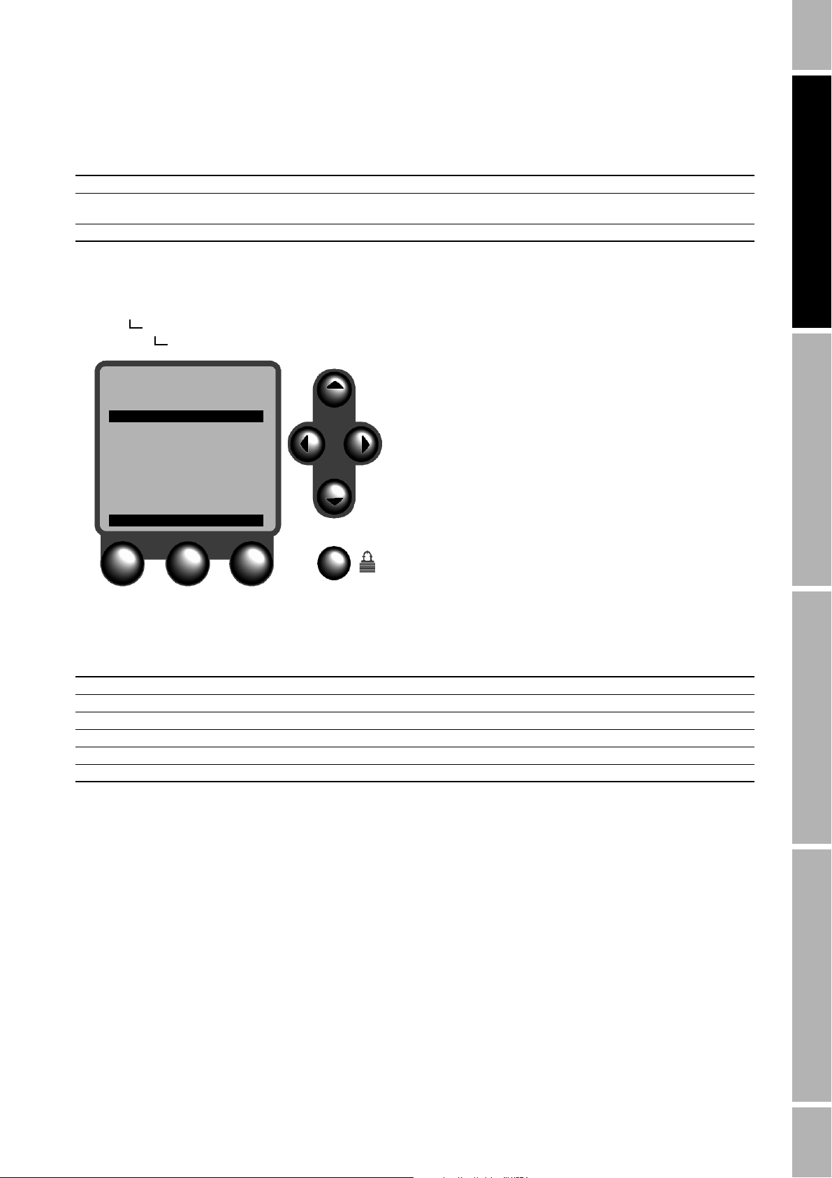
Digital Communication continued
Table 9-1. Headers and footer for printer ticket
Variable Default Description
Text Not applicable (no text) Enter up to 21 characters of text for this line of the header or for the footer
Line feeds 1 line • Enter 1 or 2 if the font size is normal height
Font size Normal height Select normal height or double height
• Enter 2 if the font size is double height
Printer, baud rate, and bits To configure the printer, baud rate, parity, data bits,
Configuration
Digital comm
Configure printer
Configure Printer
↓↑
Baud Rate
9600
Parity
None
Data Bits
8
Start Bits
1
CHG HELP EXIT
start bits, and stop bits:
1. Press the security button on the display face.
2. Select Configuration.
3. Select Digital Comm.
4. Select Configure Printer.
5. Use the function keys and cursor control buttons
to configure the parameters that are listed in
Table 9-2.
Typical tickets are illustrated in Figure 9-2 and
Figure 9-3, page 60.
• Figure 9-2 illustrates a typical process monitor
ticket.
• Figure 9-3 illustrates a typical batch ticket.
Configuration: PW and Language Operation ModeConfiguration: Custody TransferConfiguration: Digital Communication
Table 9-2. Printer setup variables
Variable Default Description
Printer select Epson TM-U295 Select Epson TM-U295, Digitec 6610A, or generic
Baud rate 9600 bps Select 1200, 2400, 4800, or 9600 bps to match baud rate for the selected printer
Parity None Select none, odd, or even to match parity bits for the selected printer
Data bits 8 bits Enter 7 or 8 data bits to match data bits for the selected printer
Start bits 1 bit This variable is fixed at 1 start bit and cannot be changed
Stop bits 1 bit Enter 1 or 2 stop bits to match stop bits for the selected printer
Series 3000 Detailed Setup Manual 59

Digital Communication continued
Figure 9-2. Typical process monitor ticket
LINE 1
LINE 2
DEVICE 1
2-JUN-1999 7:17:12
Mass Flow Rate
Units: g/s
Current value: 143.642
Mass Total
Units: g
Current value: 841.64
FOOTER
Figure 9-3. Typical batch ticket
LINE 1
LINE 2
DEVICE 1
2-JUN-1999 7:17:12
Preset 1
Units: g
Actual: 1000.1
Target: 1000.0
FOOTER
60 Series 3000 Detailed Setup Manual

Digital Communication continued
9.4 Weights and measures ticket The format weights and measures ticket menu
appears only if the custody transfer software and
security switch are installed.
Configuring a weights and measures ticket includes
the following procedures:
1. Configuring the headers and footer
2. Entering the start number for bills of lading
Headers and footer To configure the headers and footer:
Configuration
Digital comm
Format W&M ticket
Header line 1
Header line 2
Header line 3
Header line 4
Footer
1. Press the security button on the display face.
2. Select Configuration.
3. Select Digital Comm.
4. Select Format W&M Ticket.
5. Select Header Line 1, Header Line 2, Header
Line 3, Header Line 4, or Footer.
6. Use the function keys and cursor control buttons
to configure the parameters that are listed in
Table 9-3.
Configuration: PW and Language Operation ModeConfiguration: Custody TransferConfiguration: Digital Communication
Header line 1
Text
Line Feeds
Font Size
Normal Height
CHG HELP EXIT
1
Table 9-3. Headers and footer for weights and measures ticket
Variable Default Description
Text Not applicable (no text) Enter up to 21 characters of text for this line of the header or for the footer
Line feeds 1 line • Enter 1 or 2 if the font size is normal height
Font size Normal height Select normal height or double height
• Enter 2 if the font size is double height
Series 3000 Detailed Setup Manual 61

Digital Communication continued
Start number for bills of lading To enter the start number for bills of lading:
Configuration
Digital comm
Format W&M ticket
Start number (BOL)
Start Number (BOL)
Start Number (BOL)
CHG EXIT
12934
22
1. Press the security button on the display face.
2. Select Configuration.
3. Select Digital Comm.
4. Select Format W&M Ticket.
5. Select Start Number (BOL).
6. Use the function keys and cursor control buttons
to enter the desired start number for bills of
lading.
9.5 Printer test To perform the printer test:
Configuration
Digital comm
Printer test
ALARMS
Printer
Configure Printer
Format W&M Ticket
Printer Test
SEL EXIT
1. Press the security button on the display test.
2. Select Configuration.
3. Select Digital Comm.
4. Select Printer Test.
When the printer test is complete, the display reads,
"Print Test Complete". If printing does not occur:
• Check RS-485 output wiring. See the Series 3000
Installation Manual.
• Make sure printer configuration settings are
compatible with the selected printer. See the
instructions for the selected printer.
62 Series 3000 Detailed Setup Manual

10 Passwords and Language
10.1 About this chapter This chapter explains how to configure security and select the language
for the Person-Process Interface.
• Security includes all the software parameters listed in Figure 10-1.
• Language includes all the software parameters listed in Figure 10-2.
Figure 10-1.Security menu
Security Enable
Disable
Press 1
Passwords Maintenance Press 2
Configuration Press 3
Press 4
Weights & measures
1
If custody transfer software and security switch are installed.
1
Wor ld w ide
Europe
1
1
Switch status
Sensor zero
Batch reset
1
1
1
1
Disable
1
Enable
Front panel secure
Remote comm. secure
1
1
Configuration: PW and Language Operation ModeConfiguration: Custody TransferConfiguration: Digital Communication
Figure 10-2.Language menu
Language List of languages, one of which may be selected
10.2 Security Security enables limited access to configuration and maintenance
menus. If security is enabled, you can set up a configuration password, a
maintenance password, or configuration and maintenance passwords.
• The operator can access all software menus by entering the
configuration password.
• The operator can access the maintenance menu by entering the
maintenance password.
Series 3000 Detailed Setup Manual 63

Passwords and Language continued
Enabling security To enable security:
Security
Security
Enable Security
Disable
Enable
SAVE EXIT
1. Press the security button on the display face.
2. At the main menu, select Security.
3. At the Security menu, again select Security.
4. Select Enable, then press SAVE.
Passwords To set up passwords:
Security
Passwords
Maintenance
Configuration
Configuration
Press 1
Left
Press 2
Left
Press 3
Left
Press 4
Left
CHG EXIT
1. After enabling security as instructed above, press
EXIT to return to the security menu.
2. Select Passwords.
3. Select the type of password that will be set up.
• Select Maintenance to set up the maintenance
• Select Configuration to set up the configuration
4. Select the cursor control button that will be
pressed first, second, third, and fourth when the
password is entered.
password. The maintenance password allows
access to the maintenance menu.
password. The configuration password allows
access to all software menus.
64 Series 3000 Detailed Setup Manual

Passwords and Language continued
10.3 Security for weights and measures To configure security for weights and measures
Security
Weights & measures
Wor ld Wi d e
Europe
World Wide
Switch Status
Sensor Zero
Batch Reset
CHG EXIT
(custody transfer) applications, see Chapter 11.
Configuration: PW and Language Operation ModeConfiguration: Custody TransferConfiguration: Digital Communication
10.4 Language The language menu enables you to select the
language for all screens.
To select the language:
1. Press the security button on the display face.
Language
Language
English
German
SAVE EXIT
2. Select Language.
3. Select the desired language, then press SAVE.
Series 3000 Detailed Setup Manual 65

66 Series 3000 Detailed Setup Manual

11 Custody Transfer
11.1 About this chapter This chapter explains how to configure security for custody transfer.
11.2 Custody transfer configuration procedure
The procedure for configuring security for custody transfer includes the
following steps:
1. Configuring the applications platform.
2. If the platform is a Model 3500 or 3700, performing a sensor zero.
3. Setting the security switch.
4. For custody transfer applications in Europe, securing software
functions.
5. Installing the weights and measures seal.
Step 1 Configure the applications platform
To configure the applications platform, see Chapters 3-10.
Step 2 Perform a sensor zero (Model 3500 or 3700)
If the applications platform is a Model 3500 or 3700, perform a sensor
zero. See pages 81-83.
Step 3 Set the security switch
Configuration: PW and Language Operation ModeConfiguration: Custody TransferConfiguration: Digital Communication
Security for custody transfer will not take effect until the security switch
has been set to ON.
CAUTION
Improper handling of transmitter components can
damage the applications platform.
To prevent electrostatic discharge, wear an anti-static
wrist strap while setting the security switch.
Series 3000 Detailed Setup Manual 67

Custody Transfer continued
Setting the switch on the Model 3300 or 3500
Model 3300 or 3500 mounted in a panel
To set the security switch on a Model 3300 or 3500 mounted in a panel:
a. Loosen the captive screws in the bracket that holds the screw-type
wiring connectors or I/O cables in place on the back panel of the
applications platform.
b. Pull the bracket away from the back panel.
c. The security switch is located on the back panel. Set the switch so
the toggle is upward. See Figure 11-1.
d. Plug the bracketed wiring connectors or I/O cables onto the terminal
strips in the back panel.
e. Tighten the captive screws to secure the bracket to the back panel.
Figure 11-1.Security switch on panel-mount Model 3300 or 3500
Security switch
Security is enabled
when toggle is upward
68 Series 3000 Detailed Setup Manual

Custody Transfer continued
Model 3300 or 3500 mounted in a 19-inch (486.2 mm) DIN subrack
To set the security switch on a Model 3300 or 3500 mounted in a
subrack:
a. Loosen the captive screws that secure the front panel of the
applications platform to the guide rails in the subrack.
b. Slide the platform out of the subrack.
c. The security switch is located on the back panel of the platform. Set
the switch so the toggle is upward. See Figure 11-2.
d. Align the platform with the guide rails in the subrack.
e. Slide the platform into the subrack. Make sure the pins on the back
panel make contact with the wiring connectors.
f. Replace the top two or bottom two screws in the front panel of the
platform with the supplied lockout screws. See Figure 11-3, page 70.
g. Make sure all four front-panel screws are tightly secured to the guide
rails in the subrack.
Figure 11-2.Security switch on rack-mount Model 3300 or 3500
Configuration: PW and Language Operation ModeConfiguration: Custody TransferConfiguration: Digital Communication
Security switch
Security is enabled
when toggle is upward
Series 3000 Detailed Setup Manual 69

Custody Transfer continued
Figure 11-3.Installing lockout screws on rack-mount platform
Seal wire will be installed by
weights and measures inspector
(see step 5, page 80)
Setting the switch on the Model 3350 or 3700
Replace top 2 or bottom 2
screws with the supplied
lockout screws
2 x Lockout screw
WARNING
Explosion hazard.
In an explosive atmosphere, do not remove the circuit
board compartment cover within 2 minutes after
power has been disconnected.
Figure 11-4 identifies the circuit board compartment.
CAUTION
Improper handling of transmitter components can
damage the applications platform.
If a breaker bar or other tool is used for loosening the cover
of the circuit board compartment:
• Apply steady pressure to avoid chipping the paint.
Chipped paint can result in corrosion of the housing. If
the paint is chipped, repaint the housing.
• Do not apply excessive torque. Excessive torque can
damage the pipeline or the platform.
To set the security switch on the Model 3350 or 3700:
a. Unscrew the circuit board compartment cover.
b. The security switch is located on the panel inside the circuit board
compartment. Set the switch so the toggle is toward the mounting
bracket for the applications platform. See Figure 11-4, page 71.
c. Reinstall the cover. Tighten the cover to 12 ft-lb (16 Nm) torque.
70 Series 3000 Detailed Setup Manual

Custody Transfer continued
Figure 11-4.Security switch for Model 3350 or 3700
Circuit board
compartment
Do not open within 2
minutes after power has
been disconnected
Configuration: PW and Language Operation ModeConfiguration: Custody TransferConfiguration: Digital Communication
Security switch
Security is enabled
when toggle is toward
mounting bracket
Applicable conditions when switch is on
When the security switch is ON, the conditions listed in Ta ble 11-1
apply.
Table 11-1. Conditions in effect when security switch is on
Variable Description
View menu functions Parameters listed on page 73 are not secured
Configuration menu functions • Parameters listed in bold type on pages 73-78 are secured
Maintenance menu functions • Parameters listed in bold type on pages 78-79 are secured
Security menu functions • Parameters listed in bold type on page 80 are secured
Language menu functions Language selection is secured
• Parameters listed in gray type on pages 73-78 are not secured
• Time can be changed to one hour earlier or one hour later than the current time to
accommodate daylight savings time or standard time
• Time cannot be changed to one hour earlier or one hour later twice in succession
• Discrete batch flow source cannot be changed
• Batch cannot be disabled
• Batch totalizers count upward
• Reset on start is not available as a batch control option
• Number of decimal places in batch totals cannot be changed
• Discrete inputs cannot be configured to inhibit batch or inhibit totalizer
• Parameters listed in gray type on pages 78-79 are not secured
• Batch AOC can be calibrated
• Parameters listed in gray type on page 80 are not secured
Series 3000 Detailed Setup Manual 71

Custody Transfer continued
Security
Weights & measures
Europe
Switch status
Sensor zero
Front panel secure
Remote comm. secure
Batch reset
Front panel secure
Remote comm. secure
Sensor Zero
Front Panel Secure
Remote Comm. Secure
Step 4 Secure software functions (Europe)
For custody transfer security in Europe, you can
secure individual software parameters.
To secure the software configuration:
a. Press the security button on the display face.
b. Select Security.
c. Select Weights & Measures.
d. Select Europe.
e. Use the function buttons and cursor control
buttons to secure the parameters listed in
Table 11-2.
YES
YES
CHG EXIT
Table 11-2. Security for custody transfer in Europe
Note
The capability for performing a sensor zero or for resetting a batch using a discrete input or digital communication is not currently
available, but will be available in a later Series 3000 release
Variable Default Description
Switch status • Enabled if security switch is ON
• Disabled if security switch is OFF
Sensor zero • Front panel secure: YES
• Remote comm. secure: YES
Batch reset • Front panel secure: YES
• Remote comm. secure: YES
• Set security switch to ON to enable security. If security is enabled:
- Parameters in bold type on pages 73-80 are secured
- Parameters in gray type on pages 73-80 are not secured
• Set security switch to OFF to disable security. If security is disabled, all
parameters listed on pages 73-80 are not secured
• If security switch is ON and front panel secure is set to YES, sensor zero
cannot be performed using the display
• If security switch is ON and remote comm. secure is set to YES, sensor
zero cannot be performed using a discrete input or digital communication
• If security switch is ON and front panel secure is set to YES, a running
batch cannot be reset using the display
• If security switch is ON and remote comm. secure is set to YES, a
running batch cannot be reset using a discrete input or digital
communication
72 Series 3000 Detailed Setup Manual

Custody Transfer continued
View menu
Process monitoring Preset 1
Preset 2
Preset selections Preset 3
Batch inventory Preset 4
Preset 5
Preset 6
Process totalizers Process Freq. input total
Active alarm log Mass total
Volume total
Tot a l 4
Inventory Freq. input inventory
Mass inventory
Volume inventory
Inventory 4
LCD options Contrast
LCD backlight
Diagnostic monitor Drive gain
Density curves
Applications list Live zero
1
If density application software is installed and configured, and
if density curves have not been assigned to batch presets
under Discrete Batch.
1
Tube frequency
Configuration: PW and Language Operation ModeConfiguration: Custody TransferConfiguration: Digital Communication
Configuration menu: System
System Tag
Time Hour
Date Day
Master reset Month
Inputs See page 74
Discrete batch See page 75
Measurements See page 76
Outputs See page 77
Monitoring See page 78
Digital comm See page 78
Minute
Second
Yea r
Series 3000 Detailed Setup Manual 73

Custody Transfer continued
Configuration menu: Inputs
System See page 73
Inputs Coriolis Enable/disable Enable Coriolis
Enable sensor alarms
Alarm timeout
Configure process var Flow variables Flow damping
Density Density units
Temperature Temperature units
Sensor cal data T-Series setup
Flow factor
Flowcal temp coef
4
FCF
4
FT
4
FTG
4
FFQ
D1
D2
K1
K2
FD
4
DT
4
DTG
DFQ1
DFQ2
Dens temp coeff
Temperature slope
Temperature offset
Sensor information Sensor model no.
Sensor serial no.
Sensor material
Sensor end connection
Sensor liner
Frequency input Flow rate units
Discrete batch See page 75
Measurements See page 76
Outputs See page 77
Monitoring See page 78
Digital comm See page 78
1
If enable sensor alarms is set to NO.
2
If a sensor is not connected.
3
If an ELITE, BASIS, Model D, Model DL, or Model DT sensor is connected, or if T-Series setup is set to NO.
4
If a T-Series sensor is connected or if T-Series setup is set to YES.
5
If frequency = flow is selected.
6
If pulses/unit is selected.
7
If units/pulse is selected.
Scaling method Frequency = flow
Frequency
Flow
Pulses/unit
Units/pulse
5
5
6
7
Pulses/unit
Units/pulse
K-factor
1
Meter direction Forward
Mass units Backward
Mass low flow cutoff
Volume units
Vol low flow cutoff
Density damping
Slug low limit
Slug high limit
Slug time
Temperature damping
2
3
3
4
4
3
74 Series 3000 Detailed Setup Manual

Custody Transfer continued
Configuration menu: Discrete batch
System See page 73
Inputs See page 74
Discrete batch Flow source None
Frequency input
Mass
Vo lu me
Std vol flow
Net mass flow
Net vol flow
Control options Enable batch
Time out
No. of stages
No. of decimals
Reset on start
Count up
Enable end warning
Enable AOC
Enable overrun
Lockout target
Maximum target
Ignore source alarms
Alarm timeout
Configure presets by Quantity
Configure presets Preset 1
Preset 2
Preset 3
Preset 4
Preset 5
Preset 6
Discrete inputs End
Measurements See page 76 Discrete input 2
Outputs See page 77 Discrete event 1
Monitoring See page 78 Discrete event 2
Digital comm See page 78 Discrete event 3
Inhibit batch
Inhibit totalizer
Reset
Resume
Start
Stop
1
If density application software is installed and configured.
2
If lockout target is set to NO.
3
If Ignore source alarms is set to YES.
4
If density application software is installed and configured.
5
If no. of stages is set to 2.
6
If enable end warning is set to YES.
7
If enable overrun is set to YES.
8
If discrete event has been configured under Measurements.
1
1
1
2
3
% of target
Enable preset
Name
Density curve
Open primary
Open secondary
Close primary
End warning
Target Density curve 5
7
Overrun
None
Discrete input 1
Discrete event 4
Discrete event 5
Configuration: PW and Language Operation ModeConfiguration: Custody TransferConfiguration: Digital Communication
4
5
5
5
6
8
8
8
8
8
4
None
Density curve 1
Density curve 2
Density curve 3
Density curve 4
Density curve 6
4
4
4
4
4
4
Series 3000 Detailed Setup Manual 75

Custody Transfer continued
Configuration menu: Measurements
Flow source None
System See page 73
Inputs See page 74
Discrete batch See page 75
Measurements Totalizers Totalizer 1 Net vol flow
Totalizer 2
Totalizer 3
Flow direction Forward
Totalizer 4
Reset source
Inhibit source
Label Total label
Process comparator Discrete event 1
Discrete event 2
Discrete event 3
Discrete event 4
Discrete event 5
Event type HI
Process variable LO
HI PV value
LO PV value
3
4
Density functions See the Series 3000 Density Application Manual
Outputs See page 77
Monitoring See page 78
Digital comm See page 78
1
If density application software is installed and configured.
2
If discrete event has been configured.
3
If event type is HI, IN HI/LO, or OUT HI/LO.
4
If event type is LO, IN HI/LO, or OUT HI/LO.
Frequency input
Mass
Vo lu me
Std volume flow
Net mass flow
Reverse
Absolute val. FWD/REV
Subtractive FWD/REV
None
Discrete input 1
Discrete input 2
Discrete event 1
Discrete event 2
Discrete event 3
Discrete event 4
Discrete event 5
Primary valve
Batch in progress
Batch overrun
Batch timeout
Batch pump
Inventory label
IN HI/LO
OUT HI/LO
1
1
1
2
2
2
2
2
76 Series 3000 Detailed Setup Manual

Custody Transfer continued
Configuration menu: Outputs
System See page 73
Inputs See page 74
Discrete batch See page 75
Measurements See page 76
Outputs Discrete outputs Discrete output 1
Discrete output 2
Discrete output 3
Milliamp outputs
Milliamp output 1 Last measured value
Milliamp output 2 Internal zero
Power source Internal
External
Assignment None
Fault alarm
Discrete input 1
Discrete input 2
Discrete event 1
Discrete event 2
Discrete event 3
Discrete event 4
Discrete event 5
Primary valve
Secondary valve
Batch in progress
Batch end warn
Batch overrun
Batch timeout
Batch pump
Fault indication Downscale
Variable assignment Upscale
1
1
1
1
1
Configuration: PW and Language Operation ModeConfiguration: Custody TransferConfiguration: Digital Communication
Frequency output Flow source None
Monitoring See page 78
Digital comm See page 78
Frequency output use Totalization
Scaling method Frequency = flow
Frequency
Flow
Pulses/unit
Units/pulse
3
3
4
5
Maximum pulse width
Power Active
Fault indication Downscale
1
If discrete event is configured under Measurements.
2
If density application software is installed and configured.
3
If frequency = flow is selected.
4
If pulses/unit is selected.
5
If units/pulse is selected.
Calibration span 20 mA
4 mA
Low flow cutoff
Damping seconds
Frequency input
Mass
Vo lu me
Std vol flow
Net mass flow
Net vol flow
2
2
2
Rate control
Pulses/unit
Units/pulse
Passive
Upscale
Last measured value
Internal zero
Series 3000 Detailed Setup Manual 77

Custody Transfer continued
Configuration menu: Monitoring and digital communication
System See page 73
Inputs See page 74
Discrete batch See page 75
Measurements See page 76
Outputs See page 77
Monitoring Screen 1, line 1
Screen 1, line 2
Screen 2, line 1
Screen 2, line 2
Screen 3, line 1
Screen 3, line 2
Screen 4, line 1
Screen 4, line 2
Screen 5, line 1
Screen 5, line 2
Screen 5, line 3
Screen 5, line 4
Digital comm Configure printer Printer select Epson TM-U295
Digitec 6610A
Generic
Header line 1 Text
Header line 2 Line feeds
Footer Font size Normal height
Baud rate Double height
Parit y
Data bits
Start bits
Stop bits
Format W&M ticket
1
Header line 1
Printer test Header line 2
Header line 3
Header line 4
Footer
Start number (BOL)
1
If custody transfer software and security switch are installed.
1
1
1
1
1
1
1
Text
Line feeds
Font size
1
1
Normal height
Double height
1
1
Maintenance menu: Active alarm log, batch inventory, and process inventory
Active alarm log
Batch inventory Preset 1
Preset 2
Preset 3
Preset 4
Preset 5
Preset 6
Process inventory Frequency input
Mass
Vo lu me
Inventory 4
Calibration See page 79
Diagnostics See page 79
78 Series 3000 Detailed Setup Manual

Custody Transfer continued
Maintenance menu: Calibration and diagnostics
Active alarm log See page 78
Batch inventory See page 78
Process inventory See page 78
Calibration Sensor zero Cycles
Calibrate zero
View current data
Density Low density Density D1
High density Density D2
Flowing density Density D3
View current data Calibrate density
Density curve trim See the Series 3000 Density Application Manual
mA output trim
Meter factors Multivariable MF Density
Batch AOC Start calibration
Temperature Low temperature
Diagnostics Read external inputs Discrete inputs Discrete input 1
Simulate outputs Discrete outputs Discrete output 1
Milliamp output 1 Trim 4.0 mA
Milliamp output 2 Trim 20.0 mA
Volume Proving factor
View current data Calculate
Save calibration
High temperature
View current data
Frequency input Discrete input 2
Milliamp outputs Milliamp output 1
Frequency output Milliamp output 2
Time remaining
Result
Sensor offset (msec)
High density
Low density
Average density
Standard deviation
Calibrate density
Calibrate density
Mass
Mass and density
Mass and volume
Density and volume
Calibrate temp.
Discrete output 2
Discrete output 3
Configuration: PW and Language Operation ModeConfiguration: Custody TransferConfiguration: Digital Communication
Proving factor
Calculate
Series 3000 Detailed Setup Manual 79

Custody Transfer continued
Security menu
Security Enable
Disable
Press 1
Passwords Maintenance Press 2
Configuration Press 3
Press 4
Weights & measures
1
If custody transfer software and security switch are installed.
1
Wor ld w ide
Europe
1
1
Switch status
Sensor zero
Batch reset
1
1
1
Language menu
Language List of languages, one of which may be selected
1
Disable
1
Enable
Front panel secure
Remote comm. secure
1
1
Step 5 Install the weights and measures seal
The weights and measures inspector must install and secure the seal.
• On a Model 3300 or 3500 mounted in a panel, the inspector runs the
wire seal through the hole in the tab protruding through the bracket
that secures the wiring connectors to the back panel of the platform.
• On a Model 3300 or 3500 mounted in a subrack, the inspector runs
the wire seal through the holes in the lockout screws on the front
panel of the platform.
• On a Model 3350 or 3700, a hasp on the housing is located beside
the circuit board compartment cover. The cover has four tabs. The
inspector runs the wire seal through the hole in the hasp and the hole
in the nearest tab.
11.3 Security breach Security is breached if the security switch is set to OFF. A security
breach brings about the following conditions:
• The alarm message "Security Breach" appears on the screen. The
alarm, and the time and date when the breach occurred, are logged
in the active alarm log.
• If the operator prints a ticket by pressing the function button labeled
PRINT in the process monitor or discrete batch operation screen, a
note on the ticket reads, "Not a legal receipt. Security breached."
The security breach remains in effect until the switch is set to ON.
80 Series 3000 Detailed Setup Manual

12 Operation Mode
12.1 About this chapter This chapter explains how to use the software in operation mode.
• The process monitor is the default operation mode unless a control
function such as the discrete batch control application is present.
• If a control function is present, the control function is the default
operation mode.
12.2 Startup and display test At startup, the applications platform automatically tests its display.
During display testing, the screen darkens for approximately five
seconds. After the display test is completed:
®
1. The Micro Motion
2. An application list appears.
3. The platform enters the operation mode, as shown in Figure 12-1,
page 84, and Figure 12-2, page 85.
12.3 Sensor zero If the applications platform is a Model 3500 or 3700, a sensor zero must
be performed at initial startup.
Sensor zero establishes flowmeter response to zero flow and sets a
baseline for flow measurement.
logo appears.
Configuration: PW and Language Operation ModeConfiguration: Custody TransferConfiguration: Digital Communication
Once the sensor zero is set, it remains part of the transmitter nonvolatile
memory, and will not be affected by a power failure, brownout, or power
cycle.
CAUTION
Failure to perform a sensor zero calibration at initial
startup could cause the flowmeter to produce
inaccurate signals.
To avoid inaccurate measurements, perform a sensor zero
before putting the flowmeter into operation.
Series 3000 Detailed Setup Manual 81
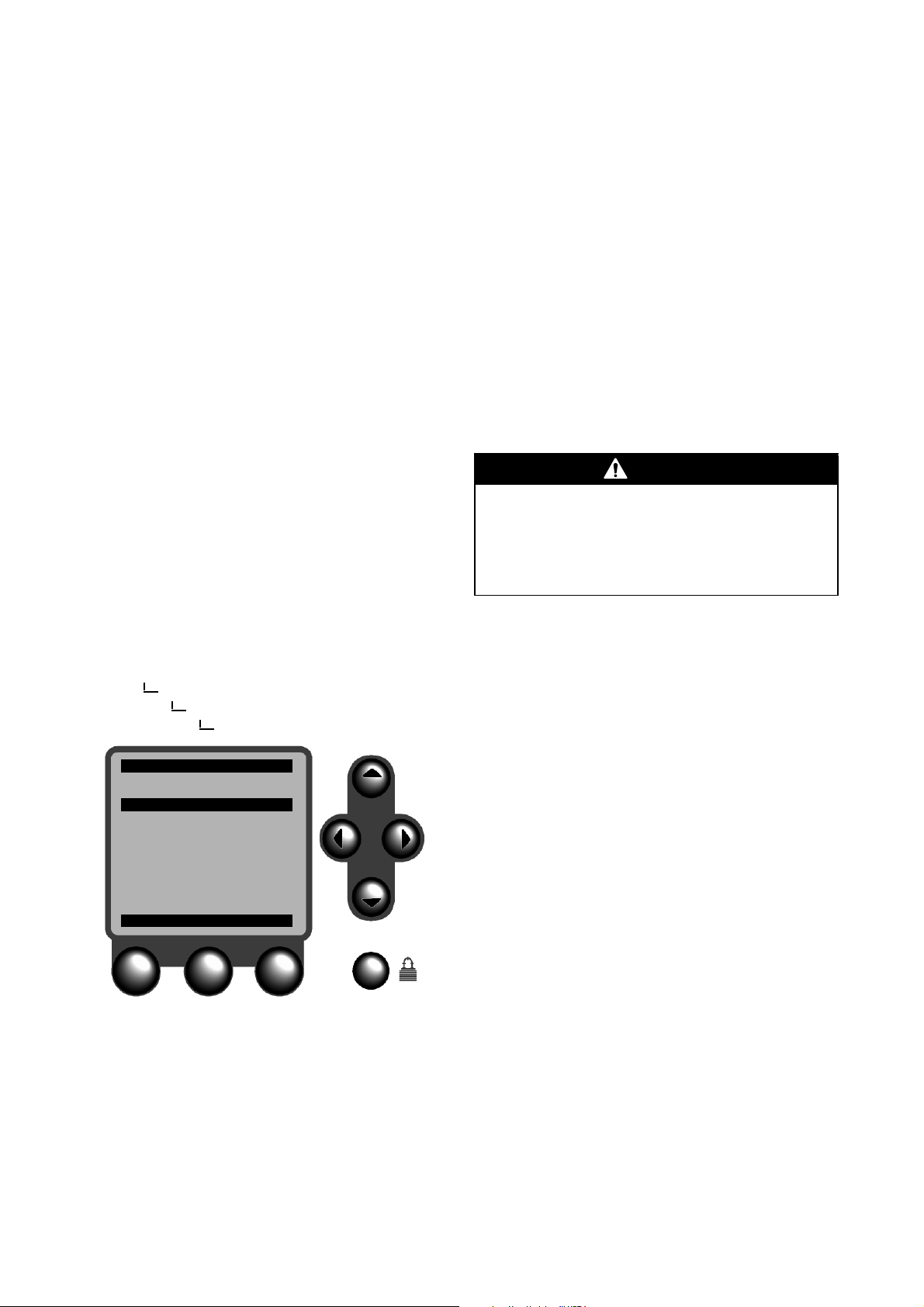
Operation Mode continued
Preparing for sensor zero calibration To prepare the flowmeter for sensor zero:
1. Install the sensor according to the appropriate
sensor instruction manual.
2. Apply power to the platform, then allow it to warm
up for at least 30 minutes.
3. Run the process fluid to be measured through the
sensor until the sensor temperature approximates
the normal process operating temperature.
4. Fill the sensor completely with process fluid under
normal process conditions of temperature,
density, pressure, etc., and ensure zero flow
through the sensor.
5. Close the shutoff valve downstream from the
sensor.
6. Make sure flow through the sensor is
completely stopped.
CAUTION
Flow through the sensor during sensor zero will
result in an inaccurate zero setting.
Make sure fluid flow through the sensor is completely
stopped during sensor zero.
Performing the sensor zero calibration To perform the sensor zero:
Maintenance
Calibration
Sensor zero
Calibrate zero
Cal In Progress
Calibrate Zero
↓
Time Remaining
24
Status
In Progress
Zero Offset (mSec)
0.082
High Density
0.432 g/cc
ABORT
1. Press the security button on the display face.
2. Select Maintenance.
3. Select Calibration.
4. Select Sensor Zero.
5. Select Calibrate Zero, then press CHG.
• During the sensor zero calibration, the time
remaining counts down to zero seconds.
• Sensor zero requires anywhere from 20
seconds to 2½ minutes, depending on the
sensor model and the density of the fluid.
During sensor zero, the calibrate zero screen
indicates the result, the zero offset in microseconds,
the high density, and the low density.
If calibration is successful, when the time remaining
is 0, the message "Calibration Complete" appears on
the screen. Press ACK to acknowledge the message,
then press EXIT to exit the calibrate zero screen.
If calibration is not successful, the message
"Calibration Failure" appears on the screen. To
diagnose the cause of the failure, see page 82.
82 Series 3000 Detailed Setup Manual

Operation Mode continued
Diagnosing sensor zero failure If the calibrate zero screen reads "Calibration
Failure," the sensor zero calibration was not
successfully completed. "Calibration Failure" could
indicate:
• Flow of fluid during the sensor zero calibration;
• Partially empty flow tubes; or
• An improperly mounted sensor.
To clear a sensor zero failure:
• Press ACK to acknowledge the "Calibration
Failure" message, then re-zero after correcting
the problem, or
• Abort the sensor zero procedure by cycling power
to the platform.
Sensor zero cycles Sensor zero cycles is the number of signal
Maintenance
Calibration
Sensor zero
Calibrate Zero
Cycles
2
Calibrate Zero
View Current Data
processing cycles required for sensor zero. The
default sensor zero cycles is 2. Increasing the
number of sensor zero cycles can improve sensor
zero accuracy by enabling the platform to derive the
offset of the flow signal from a larger number of flow
signals.
Configuration: PW and Language Operation ModeConfiguration: Custody TransferConfiguration: Digital Communication
SEL HELP EXIT
Series 3000 Detailed Setup Manual 83

Operation Mode continued
12.4 Default operation mode The process monitor, shown in Figure 12-1, is the default operation
mode unless a control function such as the discrete batch application is
present. If a control function is present:
• The control function is the default operating mode.
• Process variables can be monitored by accessing the process
monitoring menu via the view menu. For more information about the
view menu, see pages 90-93.
You can configure the process variables that will be displayed on each of
the 5 screens of the process monitor. To configure the process monitor,
see Chapter 8.
To scroll through the process monitor, press the left (¬) or right (®)
cursor control button. The number beside each arrow on the top line
indicates the screen that will be displayed if the left or right cursor control
button is pressed.
If a total appears on the screen, you can press RESET to reset it to 0.
Pressing RESET will reset only the totals on the screen that is displayed.
Press PRINT to print a ticket that includes values of process variables
on the screen that is displayed.
Figure 12-1.Person-Process Interface in default operation mode
5← DEVICE 1 →2
Mass Flow Rate
Backlit
display
2.33
g/sec
Mass Total
485.88
g
PRINT RESET VIEW
Function buttons
Cursor control
buttons
Security button
84 Series 3000 Detailed Setup Manual

Operation Mode continued
12.5 Operation mode for discrete batch control
Figure 12-2.Person-Process Interface in batch operation mode
Figure 12-2 shows the Person-Process Interface in batch operation
mode, ready to start a batch. To select a batch preset, see page 91.
The display shows that there have been zero kilograms of actual delivery
in this batch. When flow starts, the display continuously updates to show
the actual amount that has been delivered.
The display can be set up to show either the amount that has been
delivered (count up) or the amount left to be delivered (count down). To
configure count up or count down, see pages 32-33.
DEVICE 1
Preset 1
Backlit
display
Actual
0.0
Configuration: PW and Language Operation ModeConfiguration: Custody TransferConfiguration: Digital Communication
Cursor control
buttons
Editing
cursor
Function buttons
Target
kg
12.3
START HELP VIEW
Security button
If the batch controller is measuring standard volume,
net volume, or net mass, actual and target values
indicate net totals, rather than indicating gross totals
Series 3000 Detailed Setup Manual 85

Operation Mode continued
Function buttons In Figure 12-3, the display shows that the batch target is 12.3 kg.
• When you press START, flow starts.
• When the target amount has passed through the flowmeter, flow
automatically stops.
The words on the dark background at the bottom of the display tell you
the actions you can perform by pressing the three function buttons.
To start the batch, press the button on the left, labeled START.
Figure 12-3 shows what happens.
Figure 12-3.Using batch function buttons
DEVICE 1
Preset 1
Actual
0.0
Target
kg
12.3
The function of this
button changes from
START to STOP
START HELP VIEW
Display shows actual quantity,
updated continuously
DEVICE 1
Preset 1
Actual
4.4
kg
Target
12.3
STOP HELP VIEW
86 Series 3000 Detailed Setup Manual

Operation Mode continued
Figure 12-4 indicates the actions that are performed by the function
buttons during batch operation. The batch control sequence is explained
on page 89.
Figure 12-4.Function buttons in batch operation mode
DEVICE 1
Preset 1
Actual
0.0
Configuration: PW and Language Operation ModeConfiguration: Custody TransferConfiguration: Digital Communication
Target
12.3
START HELP VIEW
VIEW Access the view menu
ACK Acknowledge an alarm
HELP Show a help screen
RESUME Resume a batch that has been stopped
PRINT Print a ticket
START Start the batch
kg
STOP • Stop the batch before the target is achieved
END • End the batch before the target is achieved
RESET Reset the batch total to zero
• Batch can be resumed
• Batch cannot be resumed
Series 3000 Detailed Setup Manual 87

Operation Mode continued
Cursor control buttons The discrete batch control application can be set up to allow the
operator to change the target when the batch is not running. To enable
target adjustment, see pages 32-33.
In Figure 12-5, the line beneath the farthest right digit of the target is the
editing cursor.
• If the application has been set up to permit target adjustment, the
cursor appears on the screen whenever the batch is stopped.
• Whenever the cursor appears on the screen, you can use the cursor
control buttons to change the target.
Figure 12-5 shows how the cursor control buttons work when the editing
cursor is displayed.
Figure 12-5.Adjusting the batch target
DEVICE 1
Preset 1
Actual
0.0
kg
Target
12.3
START HELP VIEW
If the batch controller is measuring standard volume,
net volume, or net mass, actual and target values
indicate net totals, rather than indicating gross totals
Increases value at cursor
Moves cursor right
Moves cursor left
Decreases value at cursor
Cursor
88 Series 3000 Detailed Setup Manual

Operation Mode continued
Batch control sequence After the discrete batch control application has been configured as
described in Chapter 5, the batch control sequence is automatic. A
batch can be controlled automatically from the moment you press the
START button until the batch is complete. See Tabl e 12 -1.
If necessary, you can:
• Temporarily interrupt the batch by pressing STOP, then continue
without resetting the batch totalizer by pressing RESUME.
• End the batch before it is complete by pressing END. After END has
been pressed, the batch cannot be resumed.
Table 12-1. Batch events
Notes
• To configure discrete batch control options, see pages 32-33
• To configure presets, see pages 34-35
• To assign a discrete input or discrete event to a batch event, see page 37
• To assign a batch event to a discrete output, see pages 49-50
Event Description
Batch in progress • Batch is in progress
Primary valve open/close,
1-stage batch
Primary valve open/close,
2-stage batch
Secondary valve open/close,
2-stage batch
End warning • If end warning was enabled during configuration, the batch controller produces an alarm
Overrun • If overrun was enabled during configuration, the batch controller produces an alarm when
Batch pump • The system pump is operating
• Batch in progress remains active until flow stops
• If control options are configured for reset on start, pressing START resets the batch total to
zero, opens the valve, and starts the batch
• If control options are not configured for reset on start, pressing START opens the valve and
starts the batch
• The valve automatically closes when the target is achieved
• If control options are configured for reset on start and the preset is configured so open
primary is 0% of target or an amount of 0, pressing START resets the batch total to zero,
opens the primary valve, and starts the batch
• If control options are not configured for reset on start and the preset is configured so open
primary is 0% of target or an amount of 0, pressing START opens the primary valve and
starts the batch
• If the preset is configured so open primary is a value other than 0% of target or an amount
other than 0, the valve opens when the batch total achieves the open primary value
• The primary valve closes when the batch total achieves the close primary value
• If control options are configured for reset on start and the preset is configured so open
secondary is 0% of target or an amount of 0, pressing START resets the batch total, opens
the secondary valve, and starts the batch
• If control options are not configured for reset on start and the preset is configured so open
secondary is 0% of target or an amount of 0, pressing START opens the secondary valve
and starts the batch
• If the preset is configured so open secondary is a value other than 0% of target or an
amount other than 0, the secondary valve opens when the batch total achieves the open
secondary value
• The secondary valve closes when the target is achieved
when the batch total achieves the programmed end warning value
• The end warning remains active until batch completion
the batch total exceeds the target by the programmed amount or percent of target
• Overrun remains active until batch completion
• The pump remains on while the primary or secondary valve is open
Configuration: PW and Language Operation ModeConfiguration: Custody TransferConfiguration: Digital Communication
Series 3000 Detailed Setup Manual 89

Operation Mode continued
12.6 Using the view menu When you press VIEW at the operation screen, the view menu is
displayed. Figure 12-6 shows the functions performed by the function
buttons and cursor control buttons in the view menu.
For more information about view menu functions, see pages 91-95.
Figure 12-6.Working with the view menu
EXIT
ALARMS
VIEW MENU
Process Monitoring
Preset Selections
Batch Inventory
Process Totalizers
Active Alarm Log
LCD Options
Diagnostic Monitor
Density Curves
Applications List
SEL HELP EXIT
Move cursor upward
SELECT
Move cursor downward
SEL Select highlighted option
CHG Make a change to the
highlighted option
SAVE Save a change
PAUSE Pause counting of all
displayed totals
RESUME Resume counting of all
displayed totals
RESET Reset total
PRINT Print a ticket
HELP Show a help screen
RESET Reset total
EXIT Return to operation screen
VIEW Go to view menu
90 Series 3000 Detailed Setup Manual

Operation Mode continued
Process monitoring In the process monitor, process variables are
View
Process monitoring
5← DEVICE 1 →2
Mass Flow Rate
2.33
g/sec
Mass Total
485.88
g
PRINT RESET EXIT
displayed and continuously updated, in
measurement units defined during configuration.
• You can configure the process variables that will
be displayed on each of the 5 screens of the
process monitor. To configure the process
monitor, see Chapter 8.
• To scroll through the process monitor, press the
←) or right (→) cursor control button. The
left (
number beside each arrow on the top line
indicates the screen that will be displayed if the
left or right cursor control button is pressed.
• If a total appears on the screen, you can press
RESET to reset it to 0. Pressing RESET will reset
only the totals on the screen that is displayed.
• Press PRINT to print a ticket that includes values
of process variables on the screen that is
displayed.
Preset selections The discrete batch control application can be set up
View
Preset selections
Select Preset
Preset 1
Preset 2
Preset 3
Preset 4
Preset 5
Preset 6
SAVE EXIT
with as many as six different batch presets.
• Each preset has its own target.
• A preset may also have a descriptive name, which
will appear on the selection menu.
To select a batch preset:
1. At the operation screen, press VIEW.
2. Select Preset Selections. Only presets that have
been configured will be listed.
3. Select the desired preset, then press SAVE.
4. Press EXIT repeatedly to return to the operation
screen.
If a density curve has been assigned to the selected
preset, batch totals will be based on the derived
variable that was selected during configuration of the
density application. See the Series 3000 Density
Application Manual.
Configuration: PW and Language Operation ModeConfiguration: Custody TransferConfiguration: Digital Communication
Series 3000 Detailed Setup Manual 91

Operation Mode continued
Batch inventory Use the batch inventory menu to monitor inventory
View
Batch inventory
Batch Inventory
↓
Preset 1
0.0 kg
Preset 2
0.0 kg
Preset 3
0.0 kg
Preset 4
0.0 kg
EXIT
totals for batch presets.
To monitor a batch inventory total:
1. At the operation screen, press VIEW.
2. Select Batch Inventory.
3. Press EXIT repeatedly to return to the operation
screen.
To reset batch inventory totals, see page 118.
Totalizers The process totalizers menu allows you to:
• Monitor and reset process totals, and pause and
resume counting of displayed totals
• Monitor inventory totals
View
Process totalizers
Process
Process
Freq. In Total
0.00 kg
Mass Total
10.18 g
Volume Total
2.55 l
Total 4
PAU S E RESET EXIT
Process totalizers
In the view menu, you can monitor or reset process
totals, and pause and resume counting of displayed
totals.
CAUTION
If counting has been paused, pressing RESET will
cause the total to reset to a non-zero value.
To make sure the total resets to zero, press RESET
before pressing PAUSE.
To reset a process totalizer, or to pause and resume
counting of the displayed totals:
1. At the operation screen, press VIEW.
2. Select Process Totalizers.
3. Select Process.
4. Select the desired process totalizer.
• To reset the selected totalizer, press RESET.
• To pause counting of all displayed totals, press
PAU S E.
• To resume counting of all displayed totals,
press RESUME.
5. Press EXIT repeatedly to return to the operation
screen.
The value to which the process total resets depends
on whether or not counting has been paused.
92 Series 3000 Detailed Setup Manual
 Loading...