

Page 1

Configuration and Use Manual
P/N MMI-20012741, Rev. AB
January 2021
Micro Motion
®
Model 2200S Transmitters
Configuration and Use Manual
Page 2

©2021, Micro Motion, Inc. All rights reserved. ELITE and ProLink are registered trademarks, and MVD and MVD Direct Connect
are trademarks of Micro Motion, Inc., Boulder, Colorado. Micro Motion is a registered trade name of Micro Motion, Inc., Boulder,
Colorado. The Micro Motion and Emerson logos are trademarks and service marks of Emerson Electric Co. All other trademarks
are property of their respective owners.
Page 3

Contents
Chapter 1 Before You Begin . . . . . . . . . . . . . . . . . . . . . . . . . . . . . . . . . . . . . 1
1.1 Overview . . . . . . . . . . . . . . . . . . . . . . . . . . . . . . . . . . . . . . . . . . . . . . . . . . . . . . . . . . . 1
1.2 Safety . . . . . . . . . . . . . . . . . . . . . . . . . . . . . . . . . . . . . . . . . . . . . . . . . . . . . . . . . . . . . 1
1.3 Using this manual . . . . . . . . . . . . . . . . . . . . . . . . . . . . . . . . . . . . . . . . . . . . . . . . . . . . 1
1.4 Interpreting your model number . . . . . . . . . . . . . . . . . . . . . . . . . . . . . . . . . . . . . . . . . 2
1.5 Obtaining version information . . . . . . . . . . . . . . . . . . . . . . . . . . . . . . . . . . . . . . . . . . . 2
1.6 Communication tools. . . . . . . . . . . . . . . . . . . . . . . . . . . . . . . . . . . . . . . . . . . . . . . . . . 2
1.7 Flowmeter documentation . . . . . . . . . . . . . . . . . . . . . . . . . . . . . . . . . . . . . . . . . . . . . . 3
1.8 Micro Motion customer service . . . . . . . . . . . . . . . . . . . . . . . . . . . . . . . . . . . . . . . . . . 3
Chapter 2 Quick Start . . . . . . . . . . . . . . . . . . . . . . . . . . . . . . . . . . . . . . . . . 5
2.1 Overview . . . . . . . . . . . . . . . . . . . . . . . . . . . . . . . . . . . . . . . . . . . . . . . . . . . . . . . . . . . 5
2.2 Configuration overview and flowchart . . . . . . . . . . . . . . . . . . . . . . . . . . . . . . . . . . . . . 5
2.3 Configuration worksheet . . . . . . . . . . . . . . . . . . . . . . . . . . . . . . . . . . . . . . . . . . . . . . . 7
2.4 Menu flowcharts . . . . . . . . . . . . . . . . . . . . . . . . . . . . . . . . . . . . . . . . . . . . . . . . . . . . 10
2.4.1 ProLink II menus . . . . . . . . . . . . . . . . . . . . . . . . . . . . . . . . . . . . . . . . . . . 11
2.4.2 Communicator menus . . . . . . . . . . . . . . . . . . . . . . . . . . . . . . . . . . . . . . . 13
2.4.3 Display menus . . . . . . . . . . . . . . . . . . . . . . . . . . . . . . . . . . . . . . . . . . . . . 17
Chapter 3 Getting Ready to Configure . . . . . . . . . . . . . . . . . . . . . . . . . . . . . 25
3.1 Overview . . . . . . . . . . . . . . . . . . . . . . . . . . . . . . . . . . . . . . . . . . . . . . . . . . . . . . . . . . 25
3.2 Applying power . . . . . . . . . . . . . . . . . . . . . . . . . . . . . . . . . . . . . . . . . . . . . . . . . . . . . 25
3.3 Setting up and making an administrative connection . . . . . . . . . . . . . . . . . . . . . . . . 26
3.4 Working with the mA output scale . . . . . . . . . . . . . . . . . . . . . . . . . . . . . . . . . . . . . . . 26
3.4.1 Specifying the mA measurement point . . . . . . . . . . . . . . . . . . . . . . . . . . 26
3.4.2 Converting between mA output scales . . . . . . . . . . . . . . . . . . . . . . . . . . 27
3.5 Configuration tips and tricks . . . . . . . . . . . . . . . . . . . . . . . . . . . . . . . . . . . . . . . . . . . 28
3.5.1 Write-protection . . . . . . . . . . . . . . . . . . . . . . . . . . . . . . . . . . . . . . . . . . . . 28
3.5.2 Default values and ranges . . . . . . . . . . . . . . . . . . . . . . . . . . . . . . . . . . . . 28
3.5.3 Restoring factory configuration . . . . . . . . . . . . . . . . . . . . . . . . . . . . . . . . 28
3.6 Display and reporting options for process variables . . . . . . . . . . . . . . . . . . . . . . . . . 29
Chapter 4 Configuring Process Measurement . . . . . . . . . . . . . . . . . . . . . . . . 31
4.1 Overview . . . . . . . . . . . . . . . . . . . . . . . . . . . . . . . . . . . . . . . . . . . . . . . . . . . . . . . . . . 31
4.2 Characterizing the flowmeter . . . . . . . . . . . . . . . . . . . . . . . . . . . . . . . . . . . . . . . . . . 31
4.3 Configuring general flow parameters . . . . . . . . . . . . . . . . . . . . . . . . . . . . . . . . . . . . 32
4.3.1 Flow direction. . . . . . . . . . . . . . . . . . . . . . . . . . . . . . . . . . . . . . . . . . . . . . 32
4.3.2 Flow damping. . . . . . . . . . . . . . . . . . . . . . . . . . . . . . . . . . . . . . . . . . . . . . 36
4.4 Configuring mass flow measurement . . . . . . . . . . . . . . . . . . . . . . . . . . . . . . . . . . . . 37
4.4.1 Mass flow measurement unit . . . . . . . . . . . . . . . . . . . . . . . . . . . . . . . . . . 37
4.4.2 Mass flow cutoff . . . . . . . . . . . . . . . . . . . . . . . . . . . . . . . . . . . . . . . . . . . . 38
4.4.3 Defining a special unit for mass flow . . . . . . . . . . . . . . . . . . . . . . . . . . . . 38
Configuration and Use Manual i
Page 4

Contents
4.5 Configuring volume flow measurement. . . . . . . . . . . . . . . . . . . . . . . . . . . . . . . . . . . 39
4.5.1 Volume flow type . . . . . . . . . . . . . . . . . . . . . . . . . . . . . . . . . . . . . . . . . . . 39
4.5.2 Volume flow measurement unit . . . . . . . . . . . . . . . . . . . . . . . . . . . . . . . . 39
4.6 Describing gas properties for GSV flow measurement . . . . . . . . . . . . . . . . . . . . . . . 41
4.6.1 Volume or GSV flow cutoff. . . . . . . . . . . . . . . . . . . . . . . . . . . . . . . . . . . . 42
4.6.2 Defining a special unit for volume or GSV flow . . . . . . . . . . . . . . . . . . . . 43
4.7 Configuring density measurement . . . . . . . . . . . . . . . . . . . . . . . . . . . . . . . . . . . . . . 44
4.7.1 Density measurement units . . . . . . . . . . . . . . . . . . . . . . . . . . . . . . . . . . . 44
4.7.2 Density cutoff . . . . . . . . . . . . . . . . . . . . . . . . . . . . . . . . . . . . . . . . . . . . . . 44
4.7.3 Density damping . . . . . . . . . . . . . . . . . . . . . . . . . . . . . . . . . . . . . . . . . . . 45
4.7.4 Slug flow parameters . . . . . . . . . . . . . . . . . . . . . . . . . . . . . . . . . . . . . . . . 45
4.8 Configuring temperature measurement . . . . . . . . . . . . . . . . . . . . . . . . . . . . . . . . . . 46
4.8.1 Temperature measurement units . . . . . . . . . . . . . . . . . . . . . . . . . . . . . . . 46
4.8.2 Temperature damping . . . . . . . . . . . . . . . . . . . . . . . . . . . . . . . . . . . . . . . 47
4.9 Configuring pressure compensation . . . . . . . . . . . . . . . . . . . . . . . . . . . . . . . . . . . . . 47
4.9.1 Pressure correction factors . . . . . . . . . . . . . . . . . . . . . . . . . . . . . . . . . . . 47
4.9.2 Configuration procedure . . . . . . . . . . . . . . . . . . . . . . . . . . . . . . . . . . . . . 48
4.10 Damping . . . . . . . . . . . . . . . . . . . . . . . . . . . . . . . . . . . . . . . . . . . . . . . . . . . . . . . . . . 49
4.10.1 Damping and volume measurement . . . . . . . . . . . . . . . . . . . . . . . . . . . . 50
4.10.2 Interaction with the Added Damping parameter . . . . . . . . . . . . . . . . . . . 50
Chapter 5 Configuring Operational Parameters . . . . . . . . . . . . . . . . . . . . . . . 51
5.1 Overview . . . . . . . . . . . . . . . . . . . . . . . . . . . . . . . . . . . . . . . . . . . . . . . . . . . . . . . . . . 51
5.2 Configuring the display . . . . . . . . . . . . . . . . . . . . . . . . . . . . . . . . . . . . . . . . . . . . . . . 51
5.2.1 Update period . . . . . . . . . . . . . . . . . . . . . . . . . . . . . . . . . . . . . . . . . . . . . 51
5.2.2 Display language . . . . . . . . . . . . . . . . . . . . . . . . . . . . . . . . . . . . . . . . . . . 51
5.2.3 Display variables and display precision . . . . . . . . . . . . . . . . . . . . . . . . . . 52
5.2.4 Enabling and disabling display functions . . . . . . . . . . . . . . . . . . . . . . . . . 53
5.3 Configuring fault handling . . . . . . . . . . . . . . . . . . . . . . . . . . . . . . . . . . . . . . . . . . . . . 55
5.3.1 Status alarm severity . . . . . . . . . . . . . . . . . . . . . . . . . . . . . . . . . . . . . . . . 55
5.3.2 Last measured value (LMV) timeout . . . . . . . . . . . . . . . . . . . . . . . . . . . . 58
5.4 Configuring sensor parameters. . . . . . . . . . . . . . . . . . . . . . . . . . . . . . . . . . . . . . . . . 58
5.5 Configuring device parameters . . . . . . . . . . . . . . . . . . . . . . . . . . . . . . . . . . . . . . . . . 59
Chapter 6 Integrating the Meter with the Control System . . . . . . . . . . . . . . . . 61
6.1 Overview . . . . . . . . . . . . . . . . . . . . . . . . . . . . . . . . . . . . . . . . . . . . . . . . . . . . . . . . . . 61
6.2 Configuring the mA output . . . . . . . . . . . . . . . . . . . . . . . . . . . . . . . . . . . . . . . . . . . . 61
6.2.1 Process variable . . . . . . . . . . . . . . . . . . . . . . . . . . . . . . . . . . . . . . . . . . . 62
6.2.2 mA output scale (LRV and URV) . . . . . . . . . . . . . . . . . . . . . . . . . . . . . . . 62
6.2.3 AO cutoff . . . . . . . . . . . . . . . . . . . . . . . . . . . . . . . . . . . . . . . . . . . . . . . . . 63
6.2.4 Added damping . . . . . . . . . . . . . . . . . . . . . . . . . . . . . . . . . . . . . . . . . . . . 64
6.2.5 mA output fault action and fault value . . . . . . . . . . . . . . . . . . . . . . . . . . . 65
6.3 Configuring digital communications . . . . . . . . . . . . . . . . . . . . . . . . . . . . . . . . . . . . . 66
6.3.1 Digital communications fault action . . . . . . . . . . . . . . . . . . . . . . . . . . . . . 67
6.3.2 Loop current mode . . . . . . . . . . . . . . . . . . . . . . . . . . . . . . . . . . . . . . . . . 67
6.3.3 PV, SV, TV, and QV assignments . . . . . . . . . . . . . . . . . . . . . . . . . . . . . . 68
6.3.4 Burst mode . . . . . . . . . . . . . . . . . . . . . . . . . . . . . . . . . . . . . . . . . . . . . . . 69
ii Micro Motion® Model 2200S Transmitters
Page 5

Contents
Chapter 7 Testing and Moving to Production . . . . . . . . . . . . . . . . . . . . . . . . . 71
7.1 Overview . . . . . . . . . . . . . . . . . . . . . . . . . . . . . . . . . . . . . . . . . . . . . . . . . . . . . . . . . . 71
7.2 Flowmeter zero . . . . . . . . . . . . . . . . . . . . . . . . . . . . . . . . . . . . . . . . . . . . . . . . . . . . . 71
7.2.1 Preparing for zero . . . . . . . . . . . . . . . . . . . . . . . . . . . . . . . . . . . . . . . . . . 72
7.2.2 Performing the zero procedure . . . . . . . . . . . . . . . . . . . . . . . . . . . . . . . . 72
7.3 Loop testing. . . . . . . . . . . . . . . . . . . . . . . . . . . . . . . . . . . . . . . . . . . . . . . . . . . . . . . . 75
7.4 Trimming the milliamp output . . . . . . . . . . . . . . . . . . . . . . . . . . . . . . . . . . . . . . . . . . 78
7.4.1 Basic mA output trim . . . . . . . . . . . . . . . . . . . . . . . . . . . . . . . . . . . . . . . . 78
7.4.2 Expanded mA output trim . . . . . . . . . . . . . . . . . . . . . . . . . . . . . . . . . . . . 81
7.5 Using sensor simulation to test, tune, and troubleshoot the system . . . . . . . . . . . . . 82
7.6 Backing up and restoring the configuration. . . . . . . . . . . . . . . . . . . . . . . . . . . . . . . . 82
7.7 Write-protecting the configuration . . . . . . . . . . . . . . . . . . . . . . . . . . . . . . . . . . . . . . . 83
Chapter 8 Operating the Transmitter . . . . . . . . . . . . . . . . . . . . . . . . . . . . . . 85
8.1 Overview . . . . . . . . . . . . . . . . . . . . . . . . . . . . . . . . . . . . . . . . . . . . . . . . . . . . . . . . . . 85
8.2 Warm-up delay . . . . . . . . . . . . . . . . . . . . . . . . . . . . . . . . . . . . . . . . . . . . . . . . . . . . . 85
8.3 Interpreting mA output data . . . . . . . . . . . . . . . . . . . . . . . . . . . . . . . . . . . . . . . . . . . 85
8.4 Recording process variables . . . . . . . . . . . . . . . . . . . . . . . . . . . . . . . . . . . . . . . . . . . 86
8.5 Viewing process variables. . . . . . . . . . . . . . . . . . . . . . . . . . . . . . . . . . . . . . . . . . . . . 86
8.5.1 With the display . . . . . . . . . . . . . . . . . . . . . . . . . . . . . . . . . . . . . . . . . . . . 86
8.5.2 With ProLink II . . . . . . . . . . . . . . . . . . . . . . . . . . . . . . . . . . . . . . . . . . . . . 87
8.5.3 With the Communicator . . . . . . . . . . . . . . . . . . . . . . . . . . . . . . . . . . . . . . 87
8.6 Viewing and acknowledging status alarms . . . . . . . . . . . . . . . . . . . . . . . . . . . . . . . . 87
8.6.1 About status alarms . . . . . . . . . . . . . . . . . . . . . . . . . . . . . . . . . . . . . . . . . 87
8.6.2 With the display . . . . . . . . . . . . . . . . . . . . . . . . . . . . . . . . . . . . . . . . . . . . 88
8.6.3 With ProLink II . . . . . . . . . . . . . . . . . . . . . . . . . . . . . . . . . . . . . . . . . . . . . 89
8.6.4 With the Communicator . . . . . . . . . . . . . . . . . . . . . . . . . . . . . . . . . . . . . . 90
8.7 Using the totalizers and inventories . . . . . . . . . . . . . . . . . . . . . . . . . . . . . . . . . . . . . 90
8.7.1 Viewing current totals for totalizers and inventories . . . . . . . . . . . . . . . . . 90
8.7.2 Controlling totalizers and inventories . . . . . . . . . . . . . . . . . . . . . . . . . . . . 92
Chapter 9 Measurement Performance . . . . . . . . . . . . . . . . . . . . . . . . . . . . . 95
9.1 Overview . . . . . . . . . . . . . . . . . . . . . . . . . . . . . . . . . . . . . . . . . . . . . . . . . . . . . . . . . . 95
9.2 Meter validation and calibration. . . . . . . . . . . . . . . . . . . . . . . . . . . . . . . . . . . . . . . . . 95
9.2.1 Meter validation and meter factors. . . . . . . . . . . . . . . . . . . . . . . . . . . . . . 95
9.2.2 Calibration . . . . . . . . . . . . . . . . . . . . . . . . . . . . . . . . . . . . . . . . . . . . . . . . 96
9.2.3 Comparison and recommendations . . . . . . . . . . . . . . . . . . . . . . . . . . . . . 96
9.3 Performing meter validation. . . . . . . . . . . . . . . . . . . . . . . . . . . . . . . . . . . . . . . . . . . . 97
9.4 Performing density calibration . . . . . . . . . . . . . . . . . . . . . . . . . . . . . . . . . . . . . . . . . . 98
9.4.1 Preparing for density calibration . . . . . . . . . . . . . . . . . . . . . . . . . . . . . . . 98
9.4.2 Density calibration procedures. . . . . . . . . . . . . . . . . . . . . . . . . . . . . . . . . 98
9.5 Performing temperature calibration . . . . . . . . . . . . . . . . . . . . . . . . . . . . . . . . . . . . . 101
Chapter 10 Troubleshooting . . . . . . . . . . . . . . . . . . . . . . . . . . . . . . . . . . . . 103
10.1 Overview . . . . . . . . . . . . . . . . . . . . . . . . . . . . . . . . . . . . . . . . . . . . . . . . . . . . . . . . . 103
10.2 Guide to troubleshooting topics. . . . . . . . . . . . . . . . . . . . . . . . . . . . . . . . . . . . . . . . 103
10.3 Micro Motion customer service . . . . . . . . . . . . . . . . . . . . . . . . . . . . . . . . . . . . . . . . 104
10.4 Transmitter does not operate. . . . . . . . . . . . . . . . . . . . . . . . . . . . . . . . . . . . . . . . . . 104
10.5 Transmitter does not communicate . . . . . . . . . . . . . . . . . . . . . . . . . . . . . . . . . . . . . 104
10.6 Zero or calibration failure. . . . . . . . . . . . . . . . . . . . . . . . . . . . . . . . . . . . . . . . . . . . . 104
10.7 Low power and mA fault action . . . . . . . . . . . . . . . . . . . . . . . . . . . . . . . . . . . . . . . . 105
Configuration and Use Manual iii
Page 6

Contents
10.8 Fault conditions . . . . . . . . . . . . . . . . . . . . . . . . . . . . . . . . . . . . . . . . . . . . . . . . . . . . 105
10.9 HART output problems . . . . . . . . . . . . . . . . . . . . . . . . . . . . . . . . . . . . . . . . . . . . . . 105
10.10 I/O problems . . . . . . . . . . . . . . . . . . . . . . . . . . . . . . . . . . . . . . . . . . . . . . . . . . . . . . 106
10.11 Sensor simulation mode . . . . . . . . . . . . . . . . . . . . . . . . . . . . . . . . . . . . . . . . . . . . . 107
10.12 Status alarms . . . . . . . . . . . . . . . . . . . . . . . . . . . . . . . . . . . . . . . . . . . . . . . . . . . . . 107
10.13 Checking process variables . . . . . . . . . . . . . . . . . . . . . . . . . . . . . . . . . . . . . . . . . . 110
10.14 Diagnosing wiring problems . . . . . . . . . . . . . . . . . . . . . . . . . . . . . . . . . . . . . . . . . . 113
10.14.1 Checking the power supply wiring . . . . . . . . . . . . . . . . . . . . . . . . . . . . . 113
10.14.2 Checking grounding. . . . . . . . . . . . . . . . . . . . . . . . . . . . . . . . . . . . . . . . 113
10.14.3 Checking the HART communication loop . . . . . . . . . . . . . . . . . . . . . . . 113
10.15 Checking the communication device. . . . . . . . . . . . . . . . . . . . . . . . . . . . . . . . . . . . 113
10.16 Checking the output wiring and receiving device . . . . . . . . . . . . . . . . . . . . . . . . . . 114
10.17 Checking slug flow . . . . . . . . . . . . . . . . . . . . . . . . . . . . . . . . . . . . . . . . . . . . . . . . . 114
10.18 Checking output saturation . . . . . . . . . . . . . . . . . . . . . . . . . . . . . . . . . . . . . . . . . . . 115
10.19 Checking the HART address and Loop Current Mode parameter . . . . . . . . . . . . . 115
10.20 Checking the flow measurement configuration . . . . . . . . . . . . . . . . . . . . . . . . . . . . 115
10.21 Checking the characterization. . . . . . . . . . . . . . . . . . . . . . . . . . . . . . . . . . . . . . . . . 115
10.22 Checking the calibration . . . . . . . . . . . . . . . . . . . . . . . . . . . . . . . . . . . . . . . . . . . . . 116
10.23 Checking the test points . . . . . . . . . . . . . . . . . . . . . . . . . . . . . . . . . . . . . . . . . . . . . 116
10.23.1 Obtaining the test points . . . . . . . . . . . . . . . . . . . . . . . . . . . . . . . . . . . . 116
10.23.2 Drive gain problems. . . . . . . . . . . . . . . . . . . . . . . . . . . . . . . . . . . . . . . . 116
10.23.3 Low pickoff voltage . . . . . . . . . . . . . . . . . . . . . . . . . . . . . . . . . . . . . . . . 117
10.24 Checking sensor circuitry . . . . . . . . . . . . . . . . . . . . . . . . . . . . . . . . . . . . . . . . . . . . 117
Appendix A Default Values and Ranges . . . . . . . . . . . . . . . . . . . . . . . . . . . . 123
A.1 Overview . . . . . . . . . . . . . . . . . . . . . . . . . . . . . . . . . . . . . . . . . . . . . . . . . . . . . . . . . 123
A.2 Most frequently used defaults and ranges . . . . . . . . . . . . . . . . . . . . . . . . . . . . . . . 123
Appendix B Flowmeter Installation Types and Components . . . . . . . . . . . . . . . 127
B.1 Overview . . . . . . . . . . . . . . . . . . . . . . . . . . . . . . . . . . . . . . . . . . . . . . . . . . . . . . . . . 127
B.2 Transmitter components . . . . . . . . . . . . . . . . . . . . . . . . . . . . . . . . . . . . . . . . . . . . . 127
B.3 Terminal diagrams. . . . . . . . . . . . . . . . . . . . . . . . . . . . . . . . . . . . . . . . . . . . . . . . . . 128
Appendix C Model 2200S Display and User Interface . . . . . . . . . . . . . . . . . . . 129
C.1 Overview . . . . . . . . . . . . . . . . . . . . . . . . . . . . . . . . . . . . . . . . . . . . . . . . . . . . . . . . . 129
C.2 Identifying the components of the user interface . . . . . . . . . . . . . . . . . . . . . . . . . . 129
C.3 Removing and replacing the transmitter housing cover . . . . . . . . . . . . . . . . . . . . . 130
C.4 Using the display, the buttons, and the display menu system . . . . . . . . . . . . . . . . . 130
C.4.1 Accessing the display menu system . . . . . . . . . . . . . . . . . . . . . . . . . . . 130
C.4.2 Entering floating-point values from the display menus . . . . . . . . . . . . . 131
C.5 Codes and abbreviations . . . . . . . . . . . . . . . . . . . . . . . . . . . . . . . . . . . . . . . . . . . . 133
Appendix D Connecting with ProLink II Software . . . . . . . . . . . . . . . . . . . . . . 135
D.1 Overview . . . . . . . . . . . . . . . . . . . . . . . . . . . . . . . . . . . . . . . . . . . . . . . . . . . . . . . . . 135
D.2 Requirements . . . . . . . . . . . . . . . . . . . . . . . . . . . . . . . . . . . . . . . . . . . . . . . . . . . . . 135
D.3 Configuration upload/download . . . . . . . . . . . . . . . . . . . . . . . . . . . . . . . . . . . . . . . 135
D.4 Connecting from a PC to a Model 2200S transmitter . . . . . . . . . . . . . . . . . . . . . . . 135
D.5 ProLink II language . . . . . . . . . . . . . . . . . . . . . . . . . . . . . . . . . . . . . . . . . . . . . . . . . 138
iv Micro Motion® Model 2200S Transmitters
Page 7

Contents
Appendix E Using the 375 Field Communicator . . . . . . . . . . . . . . . . . . . . . . . 139
E.1 Overview . . . . . . . . . . . . . . . . . . . . . . . . . . . . . . . . . . . . . . . . . . . . . . . . . . . . . . . . . 139
E.2 Communicator device description . . . . . . . . . . . . . . . . . . . . . . . . . . . . . . . . . . . . . . 139
E.3 Connecting to a transmitter . . . . . . . . . . . . . . . . . . . . . . . . . . . . . . . . . . . . . . . . . . . 140
E.3.1 Connecting to HART clips . . . . . . . . . . . . . . . . . . . . . . . . . . . . . . . . . . . 140
E.3.2 Connecting to a multidrop network . . . . . . . . . . . . . . . . . . . . . . . . . . . . 141
E.4 Using the Communicator with the Model 2200S . . . . . . . . . . . . . . . . . . . . . . . . . . . 141
E.5 Communicator safety messages and notes . . . . . . . . . . . . . . . . . . . . . . . . . . . . . . 141
Index . . . . . . . . . . . . . . . . . . . . . . . . . . . . . . . . . . . . . . . . . . . . . . . . . . . . 143
Configuration and Use Manual v
Page 8

vi Micro Motion® Model 2200S Transmitters
Page 9

Chapter 1
Before You Begin
1.1 Overview
This chapter provides an orientation to the use of this manual. This manual describes the procedures
required to start, configure, use, maintain, and troubleshoot the Model 2200S transmitter.
If you do not know what transmitter you have, see Section 1.4 for instructions on identifying the
transmitter type from the model number on the transmitter’s tag.
1.2 Safety
Safety messages are provided throughout this manual to protect personnel and equipment. Read each
safety message carefully before proceeding to the next step.
1.3 Using this manual
This manual is organized into four sections, as described in Table 1-1.
Before You Begin
Table 1-1 Manual organization
Section Chapters Audience Description
Commissioning 2 Person responsible for process design
and device configuration
3 through 7 Detailed information for all parameters
Operation 8 Person responsible for operation Procedures for viewing process data
Maintenance and
troubleshooting
Appendices All All Reference information
9 and 10 Person responsible for periodic
Person responsible for device testing
and commissioning
maintenance and troubleshooting
“Quick start” tools for device
commissioning
that can be configured
Procedures for testing device operation
Procedures for backing up and
write-protecting configuration
and alarms, and managing totalizers
and inventories
Information and procedures for
flowmeter zero, meter proving,
calibration, and troubleshooting.
Configuration and Use Manual 1
Page 10

Before You Begin
1.4 Interpreting your model number
Model 2200S transmitter options are encoded in the model number located on the transmitter tag. The
model number is a string of the following form:
2200S*(H or K)********
In this string:
•
H = No adapter-barrier supplied with the transmitter
K = Adapter-barrier supplied with the transmitter
•
Note: See the product data sheet for information on the remaining characters in the model number.
1.5 Obtaining version information
Table 1-2 lists the version information that you may need and describes how to obtain the information.
Table 1-2 Obtaining version information
Component With ProLink II With Communicator With Display
Transmitter software View > Installed Options >
Software Revision
ProLink II Help > About ProLink II Not applicable Not applicable
Communicator
device description
Not applicable See Section E.2 Not applicable
Review > Device info >
Software rev
OFF-LINE MAINT > VER
1.6 Communication tools
To configure and administer the Model 2200S transmitter, an administrative connection is required.
You can use any of the following tools for the administrative connection:
• 375 Field Communicator with the following device description
Micro Motion 2200S Analog
•ProLink®II software, v2.8 and later
Information on setting up the administrative connection is provided in Chapter 3.
Note: Some configuration and administrative procedures can also be performed via the display
menus. However, for complete access to transmitter functions, Micro Motion recommends setting up
and using an administrative connection.
Basic information on using ProLink II and connecting ProLink II to your transmitter is provided in
Appendix D. For more information, see the ProLink II manual, available on the Micro Motion web
site (www.micromotion.com).
Basic information on the 375 Field Communicator and connecting the Communicator to your
transmitter is provided in Appendix E. For more information, see the Field Communicator
documentation available on the Micro Motion web site (www.micromotion.com).
You may be able to use other tools from Emerson Process Management, such as AMS Suite:
Intelligent Device Manager. Use of AMS is not discussed in this manual.
2 Micro Motion® Model 2200S Transmitters
Page 11

Before You Begin
1.7 Flowmeter documentation
Table 1-3 lists additional documentation that may be required or useful for your flowmeter.
Table 1-3 Flowmeter documentation resources
Topic Document
Sensor installation Sensor documentation
Transmitter installation Micro Motion® Model 2200S Transmitters: Installation Manual
Hazardous area installation See the approval documentation shipped with the transmitter, or
1.8 Micro Motion customer service
For customer service, phone the support center nearest you:
• In the U.S.A., phone
800-522-MASS (800-522-6277) (toll-free)
• In Canada and Latin America, phone +1 303-527-5200
•In Asia:
- In Japan, phone 3 5769-6803
Before You Begin
download the appropriate documentation from the Micro Motion web
site (www.micromotion.com)
- In other locations, phone +65 6777-8211 (Singapore)
•In Europe:
- In the U.K., phone 0870 240 1978 (toll-free)
- In other locations, phone +31 (0) 318 495 555 (The Netherlands)
Customers outside the U.S.A. can also email Micro Motion customer service at
International.MMISupport@EmersonProcess.com.
Configuration and Use Manual 3
Page 12

4 Micro Motion® Model 2200S Transmitters
Page 13

Chapter 2
Quick Start
2.1 Overview
This chapter provides “quick start” tools for people who already understand most or all of the
commissioning methods and options for the Model 2200S transmitter. The following tools are
provided:
• Configuration overview and flowchart – see Section 2.2
• Configuration worksheet – see Section 2.3
• Menu flowcharts
- For the Communicator – see Section 2.4.1
- For ProLink II – see Section 2.4.2
- For the display – see Section 2.4.3
If you need more help:
• On using the display, ProLink II, or the Communicator, see Appendix C, D, or E.
• On general startup and configuration topics, see Chapter 3.
Operation AppendicesMaintenance and TroubleshootingCommissioning
• On configuration parameters, see Chapters 4 through 6.
• On testing and final commissioning procedures, see Chapter 7.
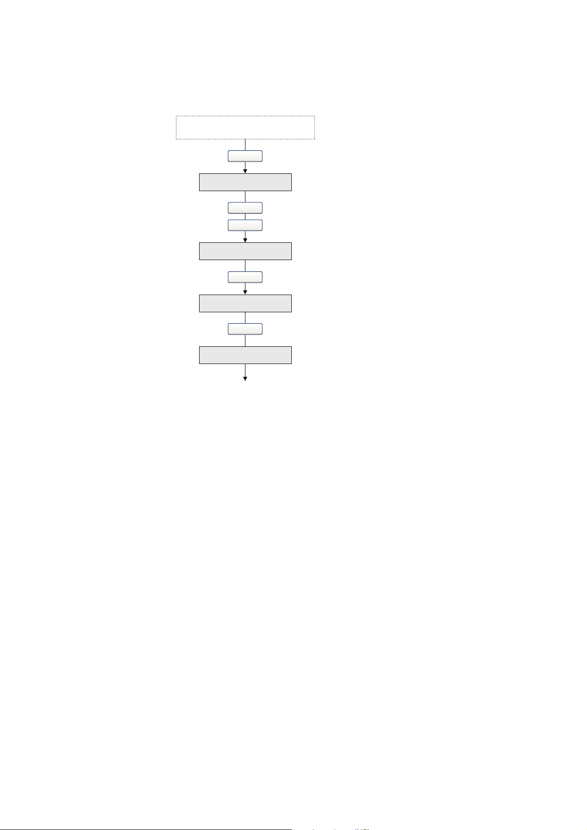
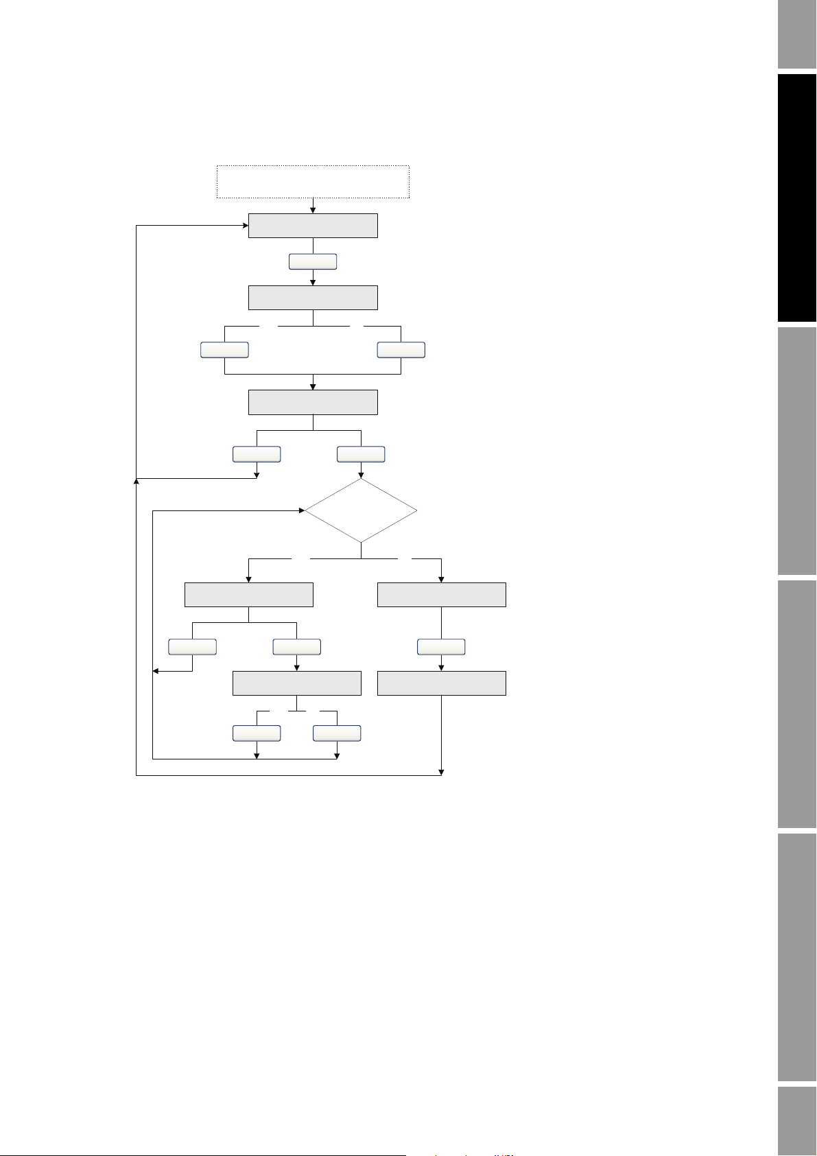
2.2 Configuration overview and flowchart
To perform a complete configuration, work though the tasks shown in Figure 2-1, in the order shown.
Detailed information and instructions for each step are provided in Chapters 3 through 7.
Configuration and Use Manual 5
Page 14

Quick Start
Test and move to production
Chapter 7
Integrate device with control system
Chapter 6
Configure operational parameters
Chapter 5
Configure process measurement
Chapter 4
Configure general flow
parameters
Configure mass flow
measurement
Configure volume flow
meaurement
Configure density
measurement
Done
Configure temperature
measurement
Characterize the
flowmeter
Volume flow type
Liquid
Gas
Define gas properties
Configure display
parameters
Configure fault handling
parameters
Configure sensor
parameters
Configure device
parameters
Configure the mA output
Configure digital
communications
Set up administrative
connection
Test
Backup
Write-protect
Configure pressure
compensation (optional)
Chapter 3
Figure 2-1 Configuration flowchart
6 Micro Motion® Model 2200S Transmitters
Page 15

Quick Start
2.3 Configuration worksheet
The configuration worksheet in this section provides a place to specify and record information about
your flowmeter and your transmitter configuration. If you are configuring multiple transmitters, make
copies of this worksheet and fill one out for each transmitter.
Configuration Worksheet Transmitter _______________________________
Transmitter model number
______________________________________________
Transmitter serial number
______________________________________________
Transmitter software
version ______________________________________________
HART Address
______________________________________________
Software tag
______________________________________________
Chapter 4
Characterization
parameters
K1
K2
FD
D1
D2
TC
Flowcal
Flow parameters Flow direction
Flow damping
Mass flow Units
Cutoff
Volume flow Type
Units
Cutoff
Density Units
Cutoff
Damping
Slug flow Low limit
_______________________________________________
_______________________________________________
_______________________________________________
_______________________________________________
_______________________________________________
_______________________________________________
_______________________________________________
Forward
Reverse
Absolute Value
Default (0.8 sec)
Other ______________________________________
Bidirectional
Negate/Forward
Negate/Absolute Value
______________________________________________
Default (0.0 g/s)
Other ______________________________________
Liquid
Gas standard volume (GSV)
Gas data ___________________________________
___________________________________
______________________________________________
Default (0.0 L/s)
Other ______________________________________
______________________________________________
Default (0.2 g/cm3)
Other ______________________________________
Default (1.6 sec)
Other ______________________________________
Default (0 g/cm3)
Other ____________
High limit
Duration
Default (5 g/cm3)
Other ____________
Default (0 sec)
Other ____________
Operation AppendicesMaintenance and TroubleshootingCommissioning
Configuration and Use Manual 7
Page 16

Quick Start
Configuration Worksheet Transmitter _______________________________
Temperature Units
______________________________________________
Damping
Pressure compensation
Enabled
Disabled
Chapter 5
Display Update period
Language
Display variables and precision Var 1
Auto scroll
Scroll rate
Off-line menu
Off-line password
Alarm menu
Totalizer start/stop
Totalizer reset
Fault handling Status alarm severity _______________________________________________
LMV timeout
Default (4.8 sec)
Other ______________________________________
Units
Flow factor
Density factor
Cal pressure
Static pressure
Default (200 millisec)
Other ______________________________________
English
French
______________________
______________________
______________________
______________________
______________________
Spanish
German
______________________
Var 2
Var 3
Var 4
Var 5
Var 6
Var 7
Var 8
Var 9
Var 1 0
Var 1 1
Var 1 2
Var 1 3
Var 1 4
Var 1 5
Enabled
Disabled
Default (10 sec)
Other _______________________________________
Enabled
Disabled
Enabled
Disabled
Enabled
Disabled
Enabled
Disabled
Enabled
Disabled
______________________
______________________
______________________
______________________
______________________
______________________
______________________
______________________
______________________
______________________
______________________
______________________
______________________
______________________
______________________
_______________________________________________
_______________________________________________
_______________________________________________
_______________________________________________
_______________________________________________
_______________________________________________
Default (0 sec)
Other ______________________________________
8 Micro Motion® Model 2200S Transmitters
Page 17

Quick Start
Configuration Worksheet Transmitter _______________________________
Sensor parameters Serial number
______________________________________________
Sensor material
______________________________________________
Liner material
______________________________________________
Flange
______________________________________________
Device parameters Descriptor
______________________________________________
Message
______________________________________________
Date
______________________________________________
Chapter 6
mA output Scale at DCS
Primary variable (PV)
LRV
URV
AO cutoff
Added damping
Fault action
12–20 mA (installation does not include adapter-barrier)
4–20 mA (installation includes adapter-barrier)
Mass flow
Volume flow
GSV flow
Temperature
Density
Drive gain
______________________________________________
______________________________________________
Default (0.0 g/s)
Other ______________________________________
Default (0.0 sec)
Other ______________________________________
Upscale
Downscale
Internal zero
None
Fault value __________
Fault value __________
Operation AppendicesMaintenance and TroubleshootingCommissioning
Configuration and Use Manual 9
Page 18

Quick Start
Configuration Worksheet Transmitter _______________________________
Digital communications Fault action
Loop current mode
Burst mode
Upscale
Downscale
Internal zero
Not-a-Number
Flow to zero
None
Enabled
Disabled
Enabled
Disabled
Fault value __________
Fault value __________
HART variables
(SV, TV, QV)
2.4 Menu flowcharts
This section provides the following menu flowcharts for the Model 2200S transmitter:
• ProLink II menus
- Main menu – see Figure 2-2
- Configuration menu – see Figures 2-3 and 2-4
• Communicator menus – see Figures 2-5 through 2-10
___ Mass flow
___ Volume flow
___ GSV flow
___ Temperature (process)
___ Density
___ Drive gain
Output
Field device variables
___ Mass total
___ Volume total
___ GSV total
___ Mass inventory
___ Volume inventory
___ GSV inventory
PV
PV and % of range
HART vars and PV
current
Field device vars
Var 1 __________
Var 2 __________
Var 3 __________
Var 3 __________
___ Board temperature
___ LPO amplitude
___ RPO amplitude
___ Raw tube frequency
___ Live zero
• Display menus
- Managing totalizers and inventories – see Figure 2-10
- Off-line maintenance menu: Top level – see Figure 2-11
- Off-line maintenance menu: Version information – see Figure 2-12
- Off-line maintenance menu: Configuration – see Figures 2-13 and 2-14
- Off-line maintenance menu: Simulation (loop testing) – see Figure 2-15
- Off-line maintenance menu: Zero – see Figure 2-16
- Alarm menu – see Figure 2-17
For information on the codes and abbreviations used on the display, see Appendix C.
These menu flowcharts are based on:
• Transmitter software v1.0
• ProLink II v2.8
• Field Communicator device description
Micro Motion 2200S Analog dev rev 1 DD rev 1
Menus may vary slightly for different versions of these components.
10 Micro Motion® Model 2200S Transmitters
Page 19

Quick Start
File
Preferences
· Enable Inventory Totals Reset
· Enable External Pressure Compensation
Installed options
Data Logging
(1)
Load from Xmtr to File
Save to Xmtr from File
License
Connect to Device
Connect to Fork Device
Disconnect
View Connection
Commissioning Wizard
Options
· ProLink II Language
· Error Log On
Tools Plug-insProLink
Configuration
Output Levels
Process Variables
Status
Alarm Log
Diagnostic Information
Calibration
Test
Totalizer Control
(1) For information about using Data
Logger, see the ProLink II manual.
2.4.1 ProLink II menus
Figure 2-2 ProLink II main menu
Operation AppendicesMaintenance and TroubleshootingCommissioning
Configuration and Use Manual 11
Page 20

Quick Start
Flow
· Flow direction
· Flow damp
·Flow cal
· Mass flow cutoff
· Mass flow units
· Vol flow cutoff
(1)
· Vol flow units
(1)
· Vol flow type
· Std gas vol flow cutoff
(2)
· Std gas vol flow units
(2)
· Std gas density
(2)
Gas wizard
(2)
· Mass factor
· Dens factor
· Vol factor
Density
· Density units
· Density damping
· Slug high limit
· Slug low limit
· Slug duration
· Low density cutoff
·K1
·K2
·FD
·D1
·D2
· Temp coeff (DT)
Temperature
· Temp units
· Temp cal factor
· Temp damping
Pressure
·Flow factor
· Dens factor
· Cal pressure
· Pressure units
Analog output
· Primary variable is
· Lower range value
· Upper range value
·AO cutoff
· AO added damp
· mA measurement point
· AO fault action
· AO fault level (level-shifted)
· AO fault level (from transmitter)
· Last measured value timeout
ProLink >
Configuration
Additional options
Device
·Tag
·Date
· Descriptor
· Message
· Sensor type
· Transmitter serial number
· Floating pt ordering
· Add comm resp delay
Digital comm settings
· Fault setting
· HART address
· Loop current mode
· HART device ID
Burst setup
· Enable burst
·Burst cmd
·Burst var 1-4
Restore Factory Configuration
Display
·Var1
·Var2
·…
· Var 15
Display precision
·Var
· Number of decimals
Display language
Display options
· Display start/stop totalizers
· Display totalizer reset
· Display auto scroll
· Display offline menu
· Display offline password
· Display alarm menu
· Display ack all alarms
Offline password
Auto scroll rate
Update period
(1) Displayed only if Vol Flow Type is
set to Liquid Volume.
(2) Displayed only if Vol Flow Type is
set to Standard Gas Volume.
Figure 2-3 ProLink II configuration menu
12 Micro Motion® Model 2200S Transmitters
Page 21

Quick Start
Sensor
· Sensor s/n
· Sensor model num
·Sensor matl
·Liner matl
· Flange
T Series
· FTG
· FFQ
·DTG
·DFQ1
·DFQ2
·K3
·D3
·D4
·K4
ProLink >
Configuration
Alarm
·Alarm
·Severity
Variable Mapping
· PV is
· SV is
·TV is
·QV is
Special Units
Base mass unit
· Base mass time
· Mass flow conv fact
· Mass flow text
· Mass total text
Base vol unit
(1)
·Base vol time
(1)
· Vol flow conv fact
(1)
· Vol flow text
(1)
· Vol total text
(1)
Base gas vol unit
(2)
· Base gas vol time
(2)
· Gas vol flow conv fact
(2)
· Gas vol flow text
(2)
· Gas vol total text
(2)
Sensor Simulation
Enable simulation mode
Mass flow
·Wave form
· Fixed value
·Period
·Minimum
·Maximum
Density
·Wave form
· Fixed value
·Period
·Minimum
·Maximum
Temperature
·Wave form
· Fixed value
·Period
·Minimum
·Maximum
(1) Displayed only if Vol Flow Type is set to Liquid Volume.
(2) Displayed only if Vol Flow Type is set to Standard Gas Volume.
On-Line Menu >
2 Process variables
View fld dev vars
1 Mass flo
2 Temp
3 Mass totl
4 Dens
5 Mass inventory
6 Vol flo
7 Vol totl
8 Vol inventory
9 Pressure
View output vars
1 View PV-Analog 1
2 View SV
(1)
3 View TV
(1)
4 View QV
(1)
View status Totlizer cntrl
1 Mass totl
2 Vol totl
3 Start totalizer
4 Stop totalizer
5 Reset all totals
6 Reset mass total
7 Reset volume total
2 3 41
(1) Can be used to change the assignment.
Figure 2-4 ProLink II configuration menu continued
Operation AppendicesMaintenance and TroubleshootingCommissioning
Figure 2-5 Communicator process variables menu
Configuration and Use Manual 13
2.4.2 Communicator menus
Page 22

Quick Start
On-Line Menu >
4 Diag/Service
Test/Status
1 View status
2 Self test
Loop test
1 Fix analog out 1
Calibration
1 Auto zero
2 Density cal
Perform diagnostic action
1 Reset alarm log
2 Acknowledge all alarms
3 Reset Power On time
4 Restore factory configuration
5 Enable write protect
6 Disable write protect
7 Restore factory zero
8 Exit
2 3 7
1
Config alarms
1 Write severity
2 Read severity
3 Review severity (all)
4 Acknowledge selected alarm
5 Alarm event log
6 Refresh alarm event log
Trim analog out 1 Scaled AO1 trim
Test points
1 Status words
2 LPO
3 RPO
4 Tube
5 Drive
6 Board temperature
7 Live zero flow
8 Meter temp. T-Series
9 Input voltage
· Actual target amplitude
· Average sensor temp
· Min sensor temp
· Max sensor temp
· Min electronics temp
· Average electronics temp
· Wire RTD
·Meter RTD
·Line RTD
· Power cycle count
· Power on time
4
6
85
On-Line Menu >
5 Basic Setup
Tag PV unit Anlog 1 range values
(1)
1 PV URV (20 mA)
2 PV LRV (4 mA or 12 mA)
2
3
1
SV is
(2)
4
TV is
(2)
QV is
(2)
5
6
(1) Can also be configured from Detailed Setup menu.
(2) Can also be configured from Process Variables menu or HART
Output menu.
Figure 2-6 Communicator diagnostics/service menu
Figure 2-7 Communicator basic setup menu
14 Micro Motion® Model 2200S Transmitters
Page 23

Quick Start
On-Line Menu >
6 Detailed Setup
21
Charize sensor
1 Sensor type (read only)
2 Sensor selection
3 Flow
4 Density
5 Temp cal factor
6 Pressure compensation
7 Meter factors
8 Polling setup
9 External temp
1 D1
2 K1
3 D2
4 K2
5 Temp coeff
(1)
5 DTG
(2)
6 FD
(1)
6 DFQ1
(2)
7 DFQ2
(2)
8 DT
(2)
9 FD
(2)
·D3
(2)
·K3
(2)
·D4
(2)
·K4
(2)
1 FlowCal
(1)
1 FCF
(2)
2 FTG
(2)
3 FFQ
(2)
1 T-Series
2 Other
1 Enable pressure
2 Flow factor
3 Dens factor
4 Flowcal pressure
5 Static pressure
1 Mass factor
2 Vol factor
3 Dens factor
1 Enable ext temp
2 Static temperature
2
4
3
6
7
8
Config fld dev vars
1 Flow
2 Density
3 Temperature
4 Pressure
1 Mass flow unit
2 Mass flow cutoff
3 Spcl mass units
4 Vol flow unit
5 Vol flow cutoff
6 Spcl vol units
7 Flo direction
8 Flo damp
1
1 Density unit
2 Density damp
3 Density cutoff
4 Slug low limit
5 Slug high limit
6 Slug duration
1 Temp unit
2 Temp damp
1 Pressure unit
2
3
4
Config outputs
1 Channel setup
2 HART output
3 Modbus data
4 Fault timeout
5 Comm fault indicator
1 AO setup
1
1
1 PV is
2 Range values
(3)
3 PV AO cutoff
4 PV AO added damp
5 AO1 fault setup
1 Read Modbus data value
2 Write Modbus data value
1 Poll addr
2 Num preambles
3 Burst mode
4 Burst option
5 Burst var 1
6 Burst var 2
7 Burst var 3
8 Burst var 4
SV is
(4)
TV is
(4)
QV is
(4)
2
3
3
Additional options
(1) Displayed only if Sensor Selection is set to Other.
(2) Displayed only if Sensor Selection is set to T-Series.
(3) Can also be configured from Basic Setup menu.
(4) Can also be configured from Process Variables menu or
Basic Setup menu.
Figure 2-8 Communicator detailed setup menu
Operation AppendicesMaintenance and TroubleshootingCommissioning
Configuration and Use Manual 15
Page 24

Quick Start
On-Line Menu >
6 Detailed Setup
6
4
Device information
1 Tag
2 Descriptor
3 Message
4 Date
5 Dev id
6 Final assembly number
7 Sensor s/n
8 Sensor model
9 Output option board
· Construction materials
· Revision #s
Display setup
1 Enable/disable
2 Display variables
3 Display precision
1 Display total reset
2 Display total start/stop
3 Display auto scroll
4 Display offline menu
5 Display alarm menu
6 Display ACK All
7 Display offline password
8 Offline password
(1)
8/9 Update period
(2)
1
5
Setup simulation mode
1 Enable/disable
2 Simulate mass flow
3 Simulate temperature
4 Simulate density
(1) Displayed only if Display Offline Password is enabled.
(2) Menu number varies depending on Display Offline Password configuration.
Figure 2-9 Communicator detailed setup menu continued
16 Micro Motion® Model 2200S Transmitters
Page 25

Quick Start
STOP/START
(1)
Select
RESET
(2)
STOP/START YES?
Process variable
display
RESET YES?
Mass total Volume total
Yes No
EXIT
Yes No
Scroll
Scroll
Scroll
Select
Scroll Scroll
ScrollScrollSelect
Select
Select
(1) The transmitter must be configured to allow resetting totalizers from the display. See Section 5.2.4.
(2) The transmitter must be configured to allow starting and stopping totalizers from the display. See Section 5.2.4.
Scroll and Select simultaneously
for 4 seconds
VER
OFF-LINE MAINT
Select
SEE ALARM
Scroll
Scroll
Scroll
EXIT
CONFG
Scroll
SIM
Scroll
ZERO
Scroll
EXIT
2.4.3 Display menus
Figure 2-10 Display menu – Managing totalizers and inventories
Operation AppendicesMaintenance and TroubleshootingCommissioning
Figure 2-11 Display menu – Off-line menu, top level
Configuration and Use Manual 17
Page 26
Quick Start
Scroll and Select simultaneously
for 4 seconds
VER
Yes
Version info
Scroll
Select
Scroll
EXIT
OFF-LINE MAINT
Select
Scroll
Figure 2-12 Display menu – Maintenance – Version information
18 Micro Motion® Model 2200S Transmitters
Page 27

Quick Start
OFF-LINE MAINT
Scroll and Select simultaneously
for 4 seconds
Scroll
Select
Select
Scroll
CONFG
MASS
UNITS
VOL
(1)
DENS
TEMP
Select
Scroll
Scroll
Scroll
Scroll
PRESS
AO
12 mA
20 mA
Select
Scroll
Scroll
EXIT
Scroll
SRC
Scroll
Scroll
EXIT
MASS
MTR F
VOL
Select
Scroll
Scroll
DENS
EXIT
Scroll
Scroll
Additional options
(1) Either Vol or GSV is displayed, depending on Volume Flow Type.
Figure 2-13 Display menu – Maintenance – Configuration: Units, AO, Meter Factors
Operation AppendicesMaintenance and TroubleshootingCommissioning
Configuration and Use Manual 19
Page 28

Quick Start
VOL TYPE
VOL
Select
Scroll
EXIT
TOTALS RESET
DISPLAY
TOTALS STOP
DISPLAY OFFLN
(1)
Select
Scroll
Scroll
Scroll
DISPLAY ALARM
EXIT
Scroll
DISPLAY ACK
Scroll
AUTO SCRLL
(2)
Scroll
OFFLINE PASSW
(3)
Scroll
DISPLAY RATE
DISPLAY LANG
Scroll
Scroll
LOCK
ScrollScroll
(1) If you disable access to the offline menu, the
offline menu will disappear as soon as you exit.
To re-enable access, you must use ProLink II or
the Communicator.
(2) If Auto Scroll is enabled, a Scroll Rate screen is
displayed immediately after the Auto Scroll
screen.
(3) If Offline Password is enabled, a Change
Password screen is displayed immediately after
the Offline Password screen.
Figure 2-14 Display menu – Maintenance – Configuration: Volume Type, Display, Lock
20 Micro Motion® Model 2200S Transmitters
Page 29

Quick Start
Scroll and Select simultaneously
for 4 seconds
Yes
Scroll
Select
SET MAO
Scroll
Select
SET 16 mA
Yes
SET 20 mA
Select
(1)
Yes
Select
(1)
SET 12 mA
Yes
Select
(1)
EXIT
Scroll
Select
(2)
. . . . . . . . . . . . . . . .
Scroll
Select
(2)
. . . . . . . . . . . . . . . .
Select
(2)
. . . . . . . . . . . . . . . .
OFF-LINE MAINT
Select
Scroll
SIM
(1) Fixes the output.
(2) Unfixes the output.
Figure 2-15 Display menu – Simulation (loop testing)
Operation AppendicesMaintenance and TroubleshootingCommissioning
Configuration and Use Manual 21
Page 30

Quick Start
………………….
OFF-LINE MAINT
Scroll and Select simultaneously
for 4 seconds
Scroll
Select
Select
CAL ZERO
Troubleshoot
ZERO/YES?
CAL PASSCAL FAIL
RESTORE ZERO
RESTORE ZERO/YES?
Current zero display
Factory zero display
Select
Select
Yes No
EXIT
Scroll
Select
Scroll
Scroll
Scroll
Yes
Select
No
Scroll
ZERO
Select
Scroll
RESTORE ZERO
Scroll Select
RESTORE EXIT
SelectScroll
Scroll
Figure 2-16 Display menu – Zero
22 Micro Motion® Model 2200S Transmitters
Page 31
Quick Start
SEE ALARM
Scroll and Select simultaneously
for 4 seconds
ACK ALL
(1)
Yes
EXIT
Select
No
Alarm code
Scroll
ACK
Yes
Select
No
Active/
unacknowledged
alarms?
NoYes
Select
NO ALARM
EXIT
Scroll
Scroll
Select
Scroll
ScrollSelect
(1) This screen is displayed only if the ACK ALL
function is enabled (see Section 5.2.4) and there are
unacknowledged alarms.
Figure 2-17 Display menu – Alarms
Operation AppendicesMaintenance and TroubleshootingCommissioning
Configuration and Use Manual 23
Page 32

24 Micro Motion® Model 2200S Transmitters
Page 33

Chapter 3
Getting Ready to Configure
3.1 Overview
This chapter contains information and procedures that are required or useful for flowmeter
configuration planning and configuration. The following topics are discussed:
• Applying power to the flowmeter – see Section 3.2
• Setting up and making an administrative connection – see Section 3.3
• Working with mA output scales – see Section 3.4
• Configuration tips and tricks – see Section 3.5
• Process variables, display variables, and reporting options – see Section 3.6
3.2 Applying power
To apply power to the flowmeter:
Operation AppendicesMaintenance and TroubleshootingCommissioning
1. Close and tighten all covers.
transmitter housing cover is in place before applying power. Operating the flowmeter without
covers in place creates electrical hazards that can cause death, injury, or property damage.
2. Apply power to the mA output wiring.
The flowmeter will automatically perform diagnostic routines. When the flowmeter has completed its
power-up sequence, if the default settings are in effect:
• The display will show the current mass flow rate and measurement unit.
• If there are any active Fault or Informational alarms, the display will flash
alternately with the mass flow measurement unit.
Note: See Section 5.3.1 for information on alarm severity (Fault, Informational, and Ignore).
Note: The flowmeter is ready to receive process fluid approximately one minute after power-up.
However, the transmitter may not be warmed up sufficiently, and may exhibit minor instability or
inaccuracy. If you observe this, wait approximately ten minutes. If the condition does not disappear,
follow standard troubleshooting procedures.
WARNING! Be sure that the Warning flap is closed and the
ALM_F or ALM_I
Configuration and Use Manual 25
Page 34

Getting Ready to Configure
3.3 Setting up and making an administrative connection
To configure and make the administrative connection using the Communicator or ProLink II:
1. Make a startup connection to the transmitter using default HART parameters as listed below:
• HART address = 0
• Baud rate = 1200
• Parity = Odd
• Stop bits = 1
Note: For information on using ProLink II, see Appendix D. For information on using the
Communicator, see Appendix E.
2. Set the HART address as required. Valid HART addresses are 0–63. The HART address must
be unique on the network. You do not need to change the default address unless the transmitter
will be on a multidrop network. To set the HART address:
• Using the Communicator, select
Poll Addr
.
• Using ProLink II, click
Note: If you set the HART address to a non-zero value, Loop Current Mode is automatically disabled
and the mA output will not report process data. See Section 6.3.2 for information on enabling Loop
Current Mode.
3. If desired, set the software tag (also called the HART tag). Devices on the network may use
either the HART address or the software tag to communicate with the transmitter. To set the
software tag:
• Using the Communicator, select
• Using ProLink II, click
4. Disconnect the startup connection and reconnect using the new parameters.
3.4 Working with the mA output scale
If the Micro Motion adapter-barrier is installed, the mA signal received by the host is scaled from
4–20 mA. If the adapter-barrier is not installed, the mA signal received by the host is scaled from
12–20 mA. For the configuration and maintenance tasks listed below, you must know which scale
applies:
• Configuring the fault value (if Fault Action is set to Downscale)
• Performing a loop test on the mA output
Detailed Setup > Config Outputs > HART Output >
ProLink > Configuration > Device.
Detailed Setup > Device Information > Tag.
ProLink > Configuration > Device.
• Performing an mA output trim or scaled AO trim
• Viewing output levels
For these tasks, Micro Motion has included scale conversion routines in the Communicator device
description and in ProLink II. These tools will perform scale conversion based on the mA
measurement point (see Section 3.4.1). If you are not using the Communicator or ProLink II, you may
need to perform scale conversion manually (see Section 3.4.2).
3.4.1 Specifying the mA measurement point
The mA measurement point is used by ProLink II and the Communicator to interpret the mA data, that
is, whether to use a 12–20 mA scale or a 4–20 mA scale. Both ProLink II and the Communicator
prompt you to specify this information whenever it is needed.
26 Micro Motion® Model 2200S Transmitters
Page 35

Getting Ready to Configure
12–20 mA
12–20 mA 4–20 mA
Micro Motion adapter-barrier
DCS
DCS
XY10–()2×=
Y
X
2
---- 10+=
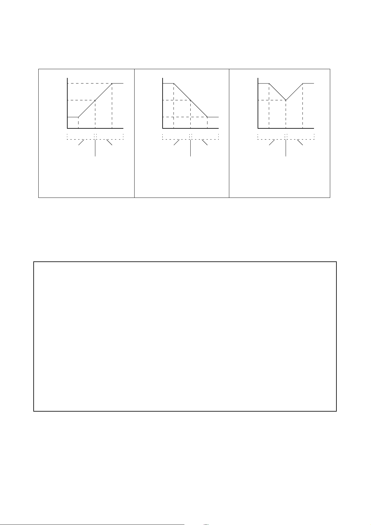
Figure 3-1 illustrates the mA measurement point options. As shown:
• If your installation does not include the Micro Motion adapter-barrier, always use 12–20 mA. .
• If your installation does include the Micro Motion adapter-barrier, be sure you know the
location of the measurement device and set the mA measurement point appropriately:
- If the mA measurement device is between the transmitter and the adapter-barrier, use
12–20 mA.
- If the mA measurement device is between the adapter-barrier and the host, use 4–20 mA.
• If you don’t know how to set the mA measurement point, specify Don’t Know. The
Communicator and ProLink II will display data for both output scales.
Figure 3-1 mA measurement point options
Operation AppendicesMaintenance and TroubleshootingCommissioning
3.4.2 Converting between mA output scales
Equations for converting between mA output scales are shown in Table 3-1.
Table 3-1 mA output scale conversion equations
Conversion Equation
12–20 mA to 4–20 mA • X = value on the 4–20 mA scale
4–20 mA to 12–20 mA • X = value on the 4–20 mA scale
• Y = value on the 12–20 mA scale
• Y = value on the 12–20 mA scale
Configuration and Use Manual 27
Page 36

Getting Ready to Configure
X 13.5 10–()2×=
X7=
Example
3.5 Configuration tips and tricks
This section provides information that may be useful before and during configuration.
3.5.1 Write-protection
Before beginning configuration, you may need to disable write-protection. To do this:
• Using ProLink II, click
write-protection option is disabled.
• Using the Communicator, select
Disable Write Protect
• Using the display:
a. Enter the display menu system.
When you connect a digital multimeter (DMM) to the I/O wiring, it reads
13.5 mA. At the mA receiving device, you see a value of 7.2 mA. You
don’t know if you have an adapter-barrier or if respanning is
implemented in the DCS. Is there a problem?
1. Convert 13.5 mA to the corresponding value on the 4–20 mA scale:
2. Compare and interpret the results: 7 vs. 7.2.
In this case, you probably do not have a configuration or wiring problem
but you may want to perform an mA output trim.
ProLink > Configuration > Device, then ensure that the
Diag/Service > Perform Diagnostic Action >
.
b. Enter the off-line maintenance menu.
c. Select the Config menu and scroll to
Lock.
d. Ensure that the Lock option is disabled.
For more details on the display menu sequence, see Figures 2-13 and 2-14.
3.5.2 Default values and ranges
Default values and ranges for the most commonly used parameters are provided in Appendix A.
3.5.3 Restoring factory configuration
If you are using ProLink II or the Communicator, you can restore the factory configuration to return
to a known state. To do this:
• Using ProLink II, click
Restore Factory Configuration.
• Using the Communicator, select
Restore Factory Configuration
ProLink > Configuration > Device, then click
Diag/Service > Perform Diagnostic Action >
.
All configuration parameters will be rewritten.
Note: This action is not available from the display.
28 Micro Motion® Model 2200S Transmitters
Page 37

Getting Ready to Configure
3.6 Display and reporting options for process variables
Table 3-2 lists the process variables that are available from the Model 2200S, and how each of them
can be displayed, reported, or queried. Refer to this list as you plan the transmitter configuration.
Table 3-2 Process variables and display/reporting/query options
Display, reporting, and query options
Process variable
Display mA output HART PV HART SV HART TV HART QV
Mass flow ✓✓ ✓✓✓✓
Volume flow
GSV flow
(1)
(1)
✓✓ ✓✓✓✓
✓✓ ✓✓✓✓
Temperature (process) ✓✓ ✓✓✓✓
Density ✓✓ ✓✓✓✓
Drive gain ✓✓ ✓✓✓✓
Mass total ✓ ✓✓✓
Volume total
GSV total
(1)
(1)
✓ ✓✓✓
✓ ✓✓✓
Mass inventory ✓ ✓✓✓
Volume inventory
GSV inventory
(1)
(1)
✓ ✓✓✓
✓ ✓✓✓
Board temperature ✓ ✓✓✓
LPO amplitude ✓ ✓✓✓
RPO amplitude ✓ ✓✓✓
Raw tube frequency ✓ ✓✓✓
Live zero ✓ ✓✓✓
(1) Volume and GSV process variables are mutually exclusive.
Operation AppendicesMaintenance and TroubleshootingCommissioning
Configuration and Use Manual 29
Page 38

30 Micro Motion® Model 2200S Transmitters
Page 39

Chapter 4
Configuring Process Measurement
4.1 Overview
The process measurement parameters control how the transmitter interprets data from the sensor.
Process measurement parameters include the following:
• Characterization parameters – see Section 4.2
• General flow parameters – see Section 4.3
• Mass flow parameters – see Section 4.4
• Volume flow parameters – see Section 4.5
• Density parameters – see Section 4.7
• Temperature parameters – see Section 4.8
• Pressure compensation parameters – see Section 4.9
Before beginning configuration, make an administrative connection to the transmitter and ensure that
you are complying with all applicable safety requirements.
Operation AppendicesMaintenance and TroubleshootingCommissioning
4.2 Characterizing the flowmeter
Characterizing the flowmeter adjusts the transmitter to compensate for the unique traits of the sensor
it is paired with. The characterization parameters, or calibration parameters, describe the sensor’s
sensitivity to flow, density, and temperature.
If the transmitter and sensor were ordered together, the flowmeter was characterized at the factory.
You need to characterize the flowmeter only if the transmitter and sensor are being paired together for
the first time. However, you may want to verify the characterization parameters.
The characterization parameters are listed in Table 4-1. The characterization parameters for your
sensor are provided on the sensor tag.
Configuration and Use Manual 31
Page 40

Configuring Process Measurement
19.0005.13
0.0010
0.9980
12502.000
14282.000
4.44000
310
12500142864.44
Table 4-1 Characterization parameters
Parameter Description Sample sensor tag
K1 Tube period when sensor is filled with air
K2 Tube period when sensor is filled with water
FD Density correction factor for high flow rates
D1 Density of air for K1
D2 Density of water for K2
TC Temperature coefficient to compensate for the
Flowcal Flow calibration factor to define the
effect of temperature on the density
measurement
relationship between sensor data and mass
flow rate and compensate for the effect of
temperature on the mass measurement
Configuration
To characterize the flowmeter using the Communicator:
1. Select
Detailed Setup > Charize Sensor.
2. In the Sensor Selection menu, select
3. In the Flow menu, set the
FlowCal parameter.
4. In the Density menu, set the remainder of the parameters listed in Table 4-1.
To characterize the flowmeter using ProLink II:
1. Click
ProLink > Configuration.
2. On the Device panel, set Sensor Type to Curved.
3. On the Flow panel, set the
Flow Cal parameter.
4. On the Density panel, set the remainder of the parameters listed in Table 4-1.
4.3 Configuring general flow parameters
The general flow parameters include:
• Flow Direction
• Flow Damping
4.3.1 Flow direction
The Flow Direction parameter controls how the transmitter reports flow rate and how flow is added to
or subtracted from the totalizers, under conditions of forward flow, reverse flow, or zero flow.
Other.
• Forward (positive) flow moves in the direction of the arrow on the sensor.
• Reverse (negative) flow moves in the direction opposite of the arrow on the sensor.
32 Micro Motion® Model 2200S Transmitters
Page 41

Configuring Process Measurement
Reverse
flow
(1)
20
16
12
x0
20
16
12
-x x0
mA output configuration:
•URV = x
•LRV = 0
To set the LRV and URV, see Section 6.2.2.
Forward
flow
(2)
Zero flow
Reverse
flow
(1)
Forward
flow
(2)
Zero flow
Flow direction parameter:
• Forward only
Flow direction parameter:
• Reverse only
• Negate/Forward only
20
16
12
-x x0
Reverse
flow
(1)
Forward
flow
(2)
Zero flow
Flow direction parameter:
• Absolute value
• Bidirectional
• Negate/Bidirectional
(1) Process fluid flowing in opposite direction from flow direction arrow on sensor.
(2) Process fluid flowing in same direction as flow direction arrow on sensor.
-x
mA output
mA output
mA output
Options for Flow Direction include:
•Forward
•Reverse
• Absolute Value
• Bidirectional
• Negate/Forward
• Negate/Absolute Value
Effects of flow direction
For the effect of Flow Direction on the mA output (i.e., a flow variable has been assigned to the mA
output):
• See Figure 4-1 if the LRV is set to 0 (zero flow).
• See Figure 4-2 if the LRV is set to a negative value.
In both figures, the mA output scale is 12–20 mA. If your installation includes the Micro Motion
adapter-barrier, adjust the y axis as follows:
•URV = 20 mA
Operation AppendicesMaintenance and TroubleshootingCommissioning
• Midpoint = 12 mA
•LRV = 4mA
For a discussion of these figures, see the examples following the figures.
For the effect of Flow Direction on totalizers and the flow values reported via digital communications,
see Table 4-2.
Figure 4-1 Effect of flow direction on mA output: LRV = 0
Configuration and Use Manual 33
Page 42
Configuring Process Measurement
Reverse
flow
(1)
mA output
20
16
12
–x x0
20
16
–x x0
mA output configuration:
•URV = x
•LRV = –x
• –x < 0
To set the LRV and URV, see Section 6.2.2.
Forward
flow
(2)
Zero flow
Reverse
flow
(1)
Forward
flow
(2)
Zero flow
Flow direction parameter:
• Forward only
Flow direction parameter:
• Reverse only
• Negate/Forward only
20
16
12
–x x0
Reverse
flow
(1)
Forward
flow
(2)
Zero flow
Flow direction parameter:
• Absolute value
• Bidirectional
• Negate/Bidirectional
(1) Process fluid flowing in opposite direction from flow direction arrow on sensor.
(2) Process fluid flowing in same direction as flow direction arrow on sensor.
mA output
mA output
12
Figure 4-2 Effect of flow direction on mA output: LRV < 0
Example 1
Configuration:
• Flow direction = Forward Only
• mA output: LRV = 0 g/s; URV = 100 g/s
(See the first graph in Figure 4-1.)
As a result:
• Under conditions of zero flow, the mA output of the transmitter is
12 mA.
• Under conditions of reverse flow, the mA output saturates at
11.9 mA.
• Under conditions of forward flow, up to a flow rate of 100 g/s, the
mA output of the transmitter varies between 12 mA and 20 mA in
proportion to (the absolute value of) the flow rate.
• Under conditions of forward flow, if (the absolute value of) the flow
rate equals or exceeds 100 g/s, the mA output will be proportional
to the flow rate up to 20.5 mA, and will be level at 20.5 mA at
higher flow rates.
34 Micro Motion® Model 2200S Transmitters
Page 43

Configuring Process Measurement
Example 2
Example 3
Configuration:
• Flow direction = Reverse Only
• mA output: LRV = 0 g/s; URV = 100 g/s
(See the second graph in Figure 4-1.)
As a result:
• Under conditions of forward flow or zero flow, the mA output of the
transmitter is 12 mA.
• Under conditions of reverse flow, up to a flow rate of 100 g/s, the
mA output of the transmitter varies between 12 mA and 20 mA in
proportion to the absolute value of the flow rate.
• Under conditions of reverse flow, if the absolute value of the flow
rate equals or exceeds 100 g/s, the mA output of the transmitter
will be proportional to the absolute value of the flow rate up to 20.5
mA, and will be level at 20.5 mA at higher absolute values.
Operation AppendicesMaintenance and TroubleshootingCommissioning
Configuration:
• Flow direction = Forward Only
• mA output: LRV = –100 g/s; URV = 100 g/s
(See the first graph in Figure 4-2.)
As a result:
• Under conditions of zero flow, the mA output is 12 mA (before
respanning).
• Under conditions of forward flow, up to a flow rate of 100 g/s, the
mA output of the transmitter varies between 12 mA and 20 mA in
proportion to (the absolute value of) the flow rate.
• Under conditions of forward flow, if (the absolute value of) the flow
rate equals or exceeds 100 g/s, the mA output of the transmitter is
proportional to the flow rate up to 20.5 mA, and will be level at
20.5 mA at higher flow rates.
• Under conditions of reverse flow, up to a flow rate of 100 g/s, the
mA output of the transmitter varies between 12 mA and 16 mA in
inverse proportion to the absolute value of the flow rate.
• Under conditions of reverse flow, if the absolute value of the flow
rate equals or exceeds 100 g/s, the mA output of the transmitter is
inversely proportional to the flow rate down to 11.9 mA (3.8 mA if
level-shifted), and will be level at 11.9 mA (3.8 mA) at higher
absolute values.
Configuration and Use Manual 35
Page 44

Configuring Process Measurement
Table 4-2 Effect of flow direction on totalizers and digital communications
Forward flow
Flow direction value
Forward only Increase Positive
Reverse only No change Positive
Bidirectional Increase Positive
Absolute value Increase Positive
Negate/Forward No change Negative
Negate/Bidirectional Decrease Negative
Flow totals Flow values via digital comm.
Zero flow
Flow direction value
All No change 0
Flow totals Flow values via digital comm.
Reverse flow
Flow direction value
Forward only No change Negative
Reverse only Increase Negative
Bidirectional Decrease Negative
Absolute value Increase Positive
Negate/Forward Increase Positive
Negate/Bidirectional Increase Positive
Flow totals Flow values via digital comm.
(1)
(1)
(1) Refer to the digital communications status bits for an indication of whether flow is positive or negative.
Configuration
To configure flow direction:
• Using the Communicator, select
• Using ProLink II, click
ProLink > Configuration > Flow.
Detailed Setup > Config Fld Dev Var > Flow.
Note: You cannot configure flow direction with the display.
4.3.2 Flow damping
Before configuring flow damping, review the information in Section 4.10.
Configuration
To configure flow damping:
• Using the Communicator, select
• Using ProLink II, click
ProLink > Configuration > Flow.
Detailed Setup > Config Fld Dev Var > Flow.
Note: You cannot configure flow damping with the display.
36 Micro Motion® Model 2200S Transmitters
Page 45

Configuring Process Measurement
4.4 Configuring mass flow measurement
The mass flow measurement parameters control how the flowmeter measures and reports mass flow.
You must configure:
• Mass flow measurement units
• Mass flow cutoff
Note: If you use the display, you can configure only the mass flow measurement unit.
4.4.1 Mass flow measurement unit
The default mass flow measurement unit is g/s. See Table 4-3 for a complete list of mass flow
measurement units.
If the mass flow unit you want to use is not listed, you can define a special measurement unit for mass
flow (see Section 4.4.3).
Table 4-3 Mass flow measurement units
Mass flow unit
Unit descriptionDisplay Communicator ProLink II
G/S g/s g/s Grams per second
G/MIN g/min g/min Grams per minute
G/H g/h g/hr Grams per hour
KG/S kg/s kg/s Kilograms per second
KG/MIN kg/min kg/min Kilograms per minute
KG/H kg/h kg/hr Kilograms per hour
KG/D kg/d kg/day Kilograms per day
T/MIN MetTon/min mTon/min Metric tons per minute
T/H MetTon/h mTon/hr Metric tons per hour
T/D MetTon/d mTon/day Metric tons per day
LB/S lb/s lbs/s Pounds per second
LB/MIN lb/min lbs/min Pounds per minute
LB/H lb/h lbs/hr Pounds per hour
LB/D lb/d lbs/day Pounds per day
ST/MIN STon/min sTon/min Short tons (2000 pounds) per minute
ST/H STon/h sTon/hr Short tons (2000 pounds) per hour
ST/D STon/d sTon/day Short tons (2000 pounds) per day
LT/H LTon/h lTon/hr Long tons (2240 pounds) per hour
LT/D LTon/d lTon/day Long tons (2240 pounds) per day
SPECL Spcl special Special unit (see Section 4.4.3)
Operation AppendicesMaintenance and TroubleshootingCommissioning
Configuration
To configure the mass flow measurement unit:
• Using the Communicator, select
• Using ProLink II, click
ProLink > Configuration > Flow.
Detailed Setup > Config Fld Dev Var > Flow.
• Using the display, see Figure 2-13.
Configuration and Use Manual 37
Page 46

Configuring Process Measurement
ConversionFactor
x BaseUnit(s)[]
y SpecialUnit(s)[]
---------------------------------------------=
x BaseUnit(s)[]y SpecialUnit(s)[]=
4.4.2 Mass flow cutoff
If the mass flow measurement drops below the configured mass flow cutoff, the transmitter will report
0 for the mass flowrate.
The default value for the mass flow cutoff is 0.0 g/s. The recommended setting is 5% of the sensor’s
rated maximum flow rate.
Note the following:
• The mass flow cutoff is not applied to either volume (liquid) or gas standard volume
measurement. Even if the measured mass flow drops below the mass flow cutoff, and therefore
the mass flow indicators go to zero, the volume flow rate will be calculated from the actual
mass flow process variable.
• The mass flow rate reported via the mA output may also be limited by the AO cutoff. See
Section 6.2.3 for more information.
Configuration
To configure the mass flow cutoff:
• Using the Communicator, select
• Using ProLink II, click
ProLink > Configuration > Flow.
Detailed Setup > Config Fld Dev Var > Flow.
Note: You cannot configure the mass flow cutoff with the display.
4.4.3 Defining a special unit for mass flow
To define a special unit for mass flow:
1. Navigate to the special units menu:
• If you are using the Communicator, select
Spcl mass units
• If you are using ProLink II, click
.
ProLink > Configuration > Special Units.
Detailed Setup > Config Fld Dev Var > Flow >
Note: You cannot define a special unit for mass flow with the display.
2. Specify the existing mass unit that the special unit will be based on.
3. Specify the existing time unit that the special unit will be based on.
4. Calculate and specify the mass flow conversion factor. This value is used to calculate the
special unit from the base mass unit and the base time unit. Use the following equations:
5. Assign a name to the new special unit for mass flow.
6. Assign a name to the unit to be used for the associated mass totalizer and inventory.
38 Micro Motion® Model 2200S Transmitters
Page 47

Configuring Process Measurement
0.0625
1
16
------
=
1lb 16oz=
Example
You want to measure the mass flow in ounces per second.
1. Set the base mass unit to pounds (lb).
2. Set the base time unit to seconds (sec).
3. Calculate and set the conversion factor:
4. Set the unit name as desired, e.g., oz/sec.
5. Set the totalizer and inventory name as desired, e.g., oz.
6. Configure the transmitter to use this measurement unit for mass
flow.
4.5 Configuring volume flow measurement
The volume flow measurement parameters control how the flowmeter measures and reports volume
flow. You must configure:
• Volume flow type
Operation AppendicesMaintenance and TroubleshootingCommissioning
• Volume flow measurement units
• Volume flow cutoff
If you set Volume Flow Type to GSV, you must also specify the properties of your gas.
Note: If you use the display, you can configure only volume flow type and the volume flow
measurement unit.
4.5.1 Volume flow type
Volume Flow Type allows you to specify that your process fluid is a liquid (typical applications) or a
gas. Your choice here controls the volume measurement units that are available. If you specify Gas
Standard Volume (GSV), you must describe the properties of your gas (see Section 4.6).
Configuration
To configure Volume Flow Type:
• Using the Communicator, select
• Using ProLink II, click
ProLink > Configuration > Flow.
Detailed Setup > Config Fld Dev Var > Flow.
• Using the display, see Figure 2-14.
4.5.2 Volume flow measurement unit
Default volume measurement units are as follows:
• Liquid – liters/second
• GSV – SCFM
Configuration and Use Manual 39
Page 48

Configuring Process Measurement
For the complete list of volume flow measurement units:
• Liquid – see Table 4-4
• GSV – see Table 4-5
If the volume flow unit you want to use is not listed, you can define a special measurement unit for
volume flow (see Section 4.6.2).
Table 4-4 Volume flow measurement units – Liquid
Volume flow unit
Display Communicator ProLink II Unit description
CUFT/S Cuft/s ft3/sec Cubic feet per second
CUF/MN Cuft/min ft3/min Cubic feet per minute
CUFT/H Cuft/h ft3/hr Cubic feet per hour
CUFT/D Cuft/d ft3/day Cubic feet per day
M3/S Cum/s m3/sec Cubic meters per second
M3/MIN Cum/min m3/min Cubic meters per minute
M3/H Cum/h m3/hr Cubic meters per hour
M3/D Cum/d m3/day Cubic meters per day
USGPS gal/s US gal/sec U.S. gallons per second
USGPM gal/min US gal/min U.S. gallons per minute
USGPH gal/h US gal/hr U.S. gallons per hour
USGPD gal/d US gal/d U.S. gallons per day
MILG/D MMgal/d mil US gal/day Million U.S. gallons per day
L/S L/s l/sec Liters per second
L/MIN L/min l/min Liters per minute
L/H L/h l/hr Liters per hour
MILL/d ML/d mil l/day Million liters per day
UKGPS Impgal/s Imp gal/sec Imperial gallons per second
UKGPM Impgal/min Imp gal/min Imperial gallons per minute
UKGPH Impgal/h Imp gal/hr Imperial gallons per hour
UKGPD Impgal/d Imp gal/day Imperial gallons per day
BBL/S bbl/s barrels/sec Barrels per second
BBL/MN bbl/min barrels/min Barrels per minute
BBL/H bbl/h barrels/hr Barrels per hour
BBL/D bbl/d barrels/day Barrels per day
BBBL/S bbl/s Beer barrels/sec Beer barrels per second
BBBL/MN bbl/min Beer barrels/min Beer barrels per minute
BBBL/H bbl/h Beer barrels/hr Beer barrels per hour
BBBL/D bbl/d Beer barrels/day Beer barrels per day
SPECL Spcl special Special unit (see Section 4.6.2)
(1)
(1)
(1)
(1)
(2)
(2)
(2)
(2)
(1) Unit based on oil barrels (42 U.S gallons).
(2) Unit based on beer barrels (31 U.S gallons).
40 Micro Motion® Model 2200S Transmitters
Page 49

Configuring Process Measurement
Table 4-5 Volume flow measurement units – Gas
Volume flow unit
Display Communicator ProLink II Unit description
NM3/S Not available Nm3/sec Normal cubic meters per second
NM3/MN Not available Nm3/min Normal cubic meters per minute
NM3/H Not available Nm3/hr Normal cubic meters per hour
NM3/D Not available Nm3/day Normal cubic meters per day
NLPS Not available NLPS Normal liter per second
NLPM Not available NLPM Normal liter per minute
NLPH Not available NLPH Normal liter per hour
NLPD Not available NLPD Normal liter per day
SCFS Not available SCFS Standard cubic feet per second
SCFM Not available SCFM Standard cubic feet per minute
SCFH Not available SCFH Standard cubic feet per hour
SCFD Not available SCFD Standard cubic feet per day
SM3/S Not available Sm3/S Standard cubic meters per second
SM3/MN Not available Sm3/min Standard cubic meters per minute
SM3/H Not available Sm3/hr Standard cubic meters per hour
SM3/D Not available Sm3/day Standard cubic meters per day
SLPS Not available SLPS Standard liter per second
SLPM Not available SLPM Standard liter per minute
SLPH Not available SLPH Standard liter per hour
SLPD Not available SLPD Standard liter per day
SPECL Spcl special Special unit (see Section 4.6.2)
Operation AppendicesMaintenance and TroubleshootingCommissioning
Configuration
To configure the volume flow measurement unit:
• Using the Communicator, select
• Using ProLink II, click
ProLink > Configuration > Flow.
Detailed Setup > Config Fld Dev Var > Flow.
• Using the display, see Figure 2-13.
4.6 Describing gas properties for GSV flow measurement
You must use ProLink II to describe the properties of your gas. To describe the properties of your gas:
1. Click
ProLink > Configure > Flow.
2. If you know the standard density of your gas (density at reference conditions), enter it on this
panel, in g/cm3, and click
Configuration and Use Manual 41
Next.
Page 50

Configuring Process Measurement
3. If you do not know the standard density of your gas:
a. Click the
b. Click
Choose Gas and check the list.
Gas Wizard button.
c. If your gas is listed, select it and click
d. If your gas is not listed, click
Enter Other Gas Property and provide the required
Next.
information. You can describe your gas by molecular weight, its specific gravity, or
density. If you use density, you must enter the density value in the configured density units
and you must provide the temperature and pressure at which the density value was
determined. When you are finished, click
Next.
e. Verify the reference temperature and reference pressure. If these are not appropriate for
your application, click
Change Reference Conditions and enter new values for reference
temperature and reference pressure.
f. Click
Next. The calculated standard density value is displayed.
• If the value is correct, click
Finish. The value will be written to transmitter
configuration.
• If the value is not correct, click
Back and modify input values as required.
Note: The Gas Wizard displays density, temperature, and pressure in the configured units. If required,
you can configure the transmitter to use different units.
4.6.1 Volume or GSV flow cutoff
If the volume or GSV flow measurement drops below the configured volume or GSV flow cutoff, the
transmitter will report a value of 0 for volume flow or GSV flow.
Note the following:
• If Volume Flow Type is set to Liquid:
• The volume flow rate is affected by the density cutoff. Accordingly, if the density drops
below its configured cutoff value, the volume flow rate will go to zero even if flow is
present and the volume flow rate is above the volume flow cutoff.
• The volume flow rate is not affected by the mass flow cutoff.
• If Volume Flow Type is set to GSV, the volume flow rate is not affected by either the density
cutoff or the mass flow cutoff.
• The volume or GSV flow rate reported via the mA output may also be limited by the AO
cutoff. See Section 6.2.3 for more information.
Configuration
To configure the volume flow cutoff or GSV flow cutoff:
• Using the Communicator, select
• Using ProLink II, click
ProLink > Configuration > Flow.
Detailed Setup > Config Fld Dev Var > Flow.
Note: You cannot configure the volume flow cutoff or GSV flow cutoff with the display.
42 Micro Motion® Model 2200S Transmitters
Page 51

Configuring Process Measurement
ConversionFactor
x BaseUnit(s)[]
y SpecialUnit(s)[]
---------------------------------------------=
x BaseUnit(s)[]y SpecialUnit(s)[]=
0.126
1
8
---
=
1gal 8pints=
4.6.2 Defining a special unit for volume or GSV flow
To define a special unit for volume or GSV flow:
1. Navigate to the special units menu:
• If you are using the Communicator, select
Spcl vol units
• If you are using ProLink II, click
.
ProLink > Configuration > Special Units.
Detailed Setup > Config Fld Dev Var > Flow >
Note: You cannot define a special unit for GSV flow with the Communicator. You cannot define a
special unit for either volume flow or GSV flow with the display.
2. Specify the existing volume or GSV unit that the special unit will be based on.
3. Specify the existing time unit that the special unit will be based on.
4. Calculate and specify the volume flow or GSV conversion factor. This value is used to
calculate the special unit from the base mass unit and the base time unit. Use the following
equations:
5. Assign a name to the new special unit for volume or GSV flow.
6. Assign a name to the unit to be used for the associated volume or GSV totalizer and inventory.
Example
You want to measure the volume flow in pints per second.
Operation AppendicesMaintenance and TroubleshootingCommissioning
1. Set the base volume unit to gallons (gal).
2. Set the base time unit to seconds (sec).
3. Calculate and set the conversion factor:
4. Set the unit name as desired, e.g., pts/sec.
5. Set the totalizer and inventory name as desired, e.g., pints.
6. Configure the transmitter to use this measurement unit for volume
flow.
Configuration and Use Manual 43
Page 52

Configuring Process Measurement
4.7 Configuring density measurement
The density measurement parameters control how the flowmeter measures and reports density. You
must configure:
• Density measurement units
• Density cutoff
• Density damping
• Slug flow parameters
Note: If you use the display, you can configure only the density measurement unit.
4.7.1 Density measurement units
The default density measurement unit is g/cm3. See Table 4-6 for a complete list of density
measurement units.
Table 4-6 Density measurement units
Density unit
Unit descriptionDisplay Communicator ProLink II
SGU SGU SGU Specific gravity unit (not temperature-
corrected)
G/CM3 g/Cucm g/cm3 Grams per cubic centimeter
G/L g/L g/l Grams per liter
G/ML g/mL g/ml Grams per milliliter
KG/L kg/L kg/l Kilograms per liter
KG/M3 kg/Cum kg/m3 Kilograms per cubic meter
LB/GAL lb/gal lbs/Usgal Pounds per U.S. gallon
LB/CUF lb/Cuft lbs/ft3 Pounds per cubic foot
LB/CUI lb/CuIn lbs/in3 Pounds per cubic inch
ST/CUY STon/Cuyd sT/yd3 Short ton per cubic yard
Configuration
To configure the density measurement unit:
• Using the Communicator, select
• Using ProLink II, click
ProLink > Configuration > Density.
Detailed Setup > Config Fld Dev Var > Density.
• Using the display, see Figure 2-13.
4.7.2 Density cutoff
If the density measurement drops below the configured density cutoff, the transmitter will report a
value of 0 for density.
44 Micro Motion® Model 2200S Transmitters
Page 53

Configuring Process Measurement
Note the following:
• The density cutoff is applied to the volume (liquid) measurement. If the density drops below
its configured cutoff value, the volume flow rate will go to zero.
• The density cutoff is not applied to the GSV measurement. The measured density values are
used in GSV calculations.
Configuration
To configure the density cutoff:
• Using the Communicator, select
• Using ProLink II, click
ProLink > Configuration > Density.
Detailed Setup > Config Fld Dev Var > Density.
Note: You cannot configure the density cutoff with the display.
4.7.3 Density damping
Before configuring density damping, review the information in Section 4.10.
Configuration
To configure density damping:
• Using the Communicator, select
• Using ProLink II, click
ProLink > Configuration > Density.
Detailed Setup > Config Fld Dev Var > Density.
Note: You cannot configure density damping with the display.
4.7.4 Slug flow parameters
Slugs – gas in a liquid process or liquid in a gas process – occasionally appear in some applications.
The presence of slugs can significantly affect the process density reading. The slug flow parameters
can help the transmitter suppress extreme changes in process variables, and can also be used to
identify process conditions that require correction.
Slug flow parameters are as follows:
Operation AppendicesMaintenance and TroubleshootingCommissioning
• Low slug flow limit – the point below which a condition of slug flow will exist. Typically, this
is the lowest density point in your process’s normal density range. Default value is 0.0 g/cm
3
range is 0.0–10.0 g/cm
.
3
• High slug flow limit – the point above which a condition of slug flow will exist. Typically, this
is the highest density point in your process’s normal density range. Default value is 5.0 g/cm
3
range is 0.0–10.0 g/cm
.
3
• Slug flow duration – the number of seconds the transmitter waits for a slug flow condition
(outside the slug flow limits) to return to normal (inside the slug flow limits).
Configuration and Use Manual 45
;
;
Page 54

Configuring Process Measurement
If the transmitter detects slug flow:
• A slug flow alarm is posted immediately.
• During the slug duration period, the transmitter holds the mass flow rate at the last measured
pre-slug value, independent of the mass flow rate measured by the sensor. All outputs that
report mass flow rate and all internal calculations that include mass flow rate will use this
value.
• If slugs are still present after the slug duration period expires, the transmitter forces the mass
flow rate to 0, independent of the mass flow rate measured by the sensor. All outputs that
report mass flow rate and all internal calculations that include mass flow rate will use 0.
• When process density returns to a value within the slug flow limits, the slug flow alarm is
cleared and the mass flow rate reverts to the actual measured value.
Note: The slug flow limits must be entered in g/cm
density. Slug flow duration is entered in seconds.
Note: Raising the low slug flow limit or lowering the high slug flow limit will increase the possibility
of slug flow conditions. Conversely, lowering the low slug flow limit or raising the high slug flow limit
will decrease the possibility of slug flow conditions.
Note: If slug flow duration is set to 0, the mass flow rate will be forced to 0 as soon as slug flow is
detected.
3
, even if another unit has been configured for
Configuration
To configure slug flow parameters:
• Using the Communicator, select
• Using ProLink II, click
ProLink > Configuration > Density.
Note: You cannot configure slug flow parameters with the display.
4.8 Configuring temperature measurement
The temperature measurement parameters control how the flowmeter measures and reports
temperature. You must configure:
• Temperature measurement units
• Temperature damping
Note: If you use the display, you can configure only the temperature measurement unit.
4.8.1 Temperature measurement units
The default temperature measurement unit is °C. See Table 4-7 for a complete list of temperature
measurement units.
Detailed Setup > Config Fld Dev Var > Density.
46 Micro Motion® Model 2200S Transmitters
Page 55

Configuring Process Measurement
Table 4-7 Temperature measurement units
Temperature unit
Unit descriptionDisplay Communicator ProLink II
°C degC °C Degrees Celsius
°F degF °F Degrees Fahrenheit
°R degR °R Degrees Rankine
°K Kelvin °K Kelvin
Configuration
To configure the temperature measurement unit:
• Using the Communicator, select
Detailed Setup > Config Fld Dev Var > Temperature.
• Using ProLink II, click
ProLink > Configuration > Temperature.
• Using the display, see Figure 2-13.
4.8.2 Temperature damping
Before configuring temperature damping, review the information in Section 4.10.
Configuration
To configure temperature damping:
• Using the Communicator, select
• Using ProLink II, click
ProLink > Configuration > Temperature.
Note: You cannot configure temperature damping with the display.
4.9 Configuring pressure compensation
The Model 2200S transmitter can compensate for the effect of pressure on the sensor flow tubes.
Pressure effect is defined as the change in sensor flow and density sensitivity due to process pressure
change away from calibration pressure.
Note: Pressure compensation is optional. Perform this procedure only if required by your application.
The Model 2200S transmitter supports only static pressure compensation; i.e., the external pressure is
a known static value.
Operation AppendicesMaintenance and TroubleshootingCommissioning
Detailed Setup > Config Fld Dev Var > Temperature.
4.9.1 Pressure correction factors
When configuring pressure compensation, you must provide the flow calibration pressure – the
pressure at which the sensor was calibrated (which therefore defines the pressure at which there will
be no effect on the calibration factor). Enter 20 PSI unless the calibration document for your sensor
indicates a different calibration pressure.
Two additional pressure correction factors may be configured: one for flow and one for density. These
are defined as follows:
• Flow factor – the percent change in the flow rate per psi
• Density factor – the change in fluid density, in g/cm
Configuration and Use Manual 47
3
/psi
Page 56

Configuring Process Measurement
Enter Flow factr
Configure pressure compensation
Enter Dens factr
Enter Flowcal pressure
Enter Static Pressure
6 Pressure Comp
2 Config field dev var
Enter Pressure unit
Set pressure measurement unit
4 Pressure
Send
Home
Send
Home
1 Charize Sensor
Enable pressure comp
On-Line Menu >
6 Detailed Setup
On-Line Menu >
6 Detailed Setup
Done
Not all sensors or applications require pressure correction factors. For the pressure correction values
to be used, obtain the pressure effect values from the product data sheet for your sensor, then reverse
the signs (e.g., if the pressure effect is 0.000004, enter a pressure correction factor of –0.000004).
4.9.2 Configuration procedure
To enable and configure pressure compensation:
• With the Communicator, see Figure 4-3.
• With ProLink II, see Figure 4-4.
Note: You cannot configure pressure compensation with the display.
Figure 4-3 Configuring pressure compensation with the Communicator
48 Micro Motion® Model 2200S Transmitters
Page 57

Configuring Process Measurement
Enter Flow factor
Configure
Enter Density factor
Enter Cal pressure
Enter External Pressure
Enable External Pressure
Compensation
Enable
Apply
Enter Pressure units
Set measurement unit
Apply
View >
Preferences
ProLink >
Configuration >
Pressure
ProLink >
Configuration >
Pressure
Apply
Apply
Done
Figure 4-4 Configuring pressure compensation with ProLink II
Operation AppendicesMaintenance and TroubleshootingCommissioning
4.10 Damping
Damping helps the transmitter smooth out small, rapid measurement fluctuations. A damping value
specifies the period of time, in seconds, over which the process variable value will change to reflect
63% of the change in the actual process.
Damping can be configured for flow, density, and temperature (see Sections 4.3.2, 4.7.3, and 4.8.2.).
When you specify a new damping value, it is automatically rounded down to the nearest valid
damping value. Valid damping values are listed in Table 4-8.
Note: For gas applications, Micro Motion recommends a minimum flow damping value of 2.56.
Before setting the damping values, review the following sections for information on how the damping
values interact with other transmitter measurements and parameters.
Table 4-8 Valid damping values
Process variable Valid damping values
Flow (mass and volume) 0, 0.04, 0.08, 0.16, ... 40.96
Density 0, 0.04, 0.08, 0.16, ... 40.96
Temperature 0, 0.6, 1.2, 2.4, 4.8, ... 76.8
• A high damping value makes the output appear to be smoother because the output must change
slowly.
• A low damping value makes the output appear to be more erratic because the output changes
more quickly.
Configuration and Use Manual 49
Page 58

Configuring Process Measurement
4.10.1 Damping and volume measurement
When configuring damping values, note the following:
• Liquid volume flow is derived from mass and density measurements; therefore, any damping
applied to mass flow and density will affect liquid volume measurement.
• Gas standard volume flow is derived from mass flow measurement, but not from density
measurement. Therefore, only damping applied to mass flow will affect gas standard volume
measurement.
Be sure to set damping values accordingly.
4.10.2 Interaction with the Added Damping parameter
The mA output has a damping parameter called Added Damping. If damping is set to non-zero value
for flow, density, or temperature, the same process variable is assigned to the mA output, and Added
Damping is also set to a non-zero value, the effect of damping the process variable is calculated first,
and the added damping calculation is applied to the result of that calculation.
See Section 6.2.4 for more information on the Added Damping parameter.
50 Micro Motion® Model 2200S Transmitters
Page 59

Chapter 5
Configuring Operational Parameters
5.1 Overview
The operational parameters control the behavior of the transmitter and flowmeter system. The
following parameters can be configured:
• Display parameters – see Section 5.2
• Fault handling parameters – see Section 5.3
In addition, this chapter provides information on sensor parameters (see Section 5.4) and device
parameters (see Section 5.5). These parameters do not affect measurement or operation, but may be
useful for administration.
Before beginning configuration, ensure that you have made an administrative connection to the
transmitter and that you are complying with all applicable safety requirements.
Operation AppendicesMaintenance and TroubleshootingCommissioning
5.2 Configuring the display
You can configure a variety of parameters to control display behavior and operator actions at the
display.
5.2.1 Update period
The Update Period parameter controls how often the display is refreshed with current data. The
default is 200 milliseconds; the range is 100 milliseconds to 10,000 milliseconds (10 seconds).
Configuration
To configure Update Period:
• Using the Communicator, select
• Using ProLink II, click ProLink > Configuration > Display.
• Using the display, see Figure 2-14.
5.2.2 Display language
The display language can be set to English, French, German, or Spanish. Other languages may be
available, depending on date of purchase.
Configuration
To configure the display language:
Detailed Setup > Display Setup.
• Using the Communicator, select
• Using ProLink II, click ProLink > Configuration > Display.
• Using the display, see Figure 2-14.
Configuration and Use Manual 51
Detailed Setup > Display Setup.
Page 60

Configuring Operational Parameters
5.2.3 Display variables and display precision
The display can scroll through up to 15 process variables in any order. You can configure the process
variables to be displayed and the order in which they should appear.
Auto Scroll may or may not be enabled:
• If Auto Scroll is enabled, each configured display variable will be shown for the number of
seconds specified for Scroll Rate.
• Whether Auto Scroll is enabled or not, the operator can manually scroll through the configured
display variables by pressing
Additionally, you can configure display precision for each display variable. Display precision controls
the number of digits to the right of the decimal place shown on the display. Precision can be set to any
value from 0 to 5.
Note: The display precision does not affect the precision of the value as stored, processed, or reported
via the mA output or digital communications.
Note: The display is capable of displaying special measurement units. If you have defined a special
measurement unit, it will be listed for selection.
Table 5-1 shows an example of a display variable configuration. Notice that you can repeat variables,
and you can also specify None for any display variable except Display Var 1. For information on how
the display variables will appear on the display, see Appendix C.
Scroll.
Table 5-1 Example of a display variable configuration
Display variable Process variable
Display variable 1
Display variable 2 Mass totalizer
Display variable 3 Volume flow
Display variable 4 Volume totalizer
Display variable 5 Density
Display variable 6 Temperature
Display variable 7 External temperature
Display variable 8 External pressure
Display variable 9 Mass flow
Display variable 10 None
Display variable 11 None
Display variable 12 None
Display variable 13 None
Display variable 14 None
Display variable 15 None
(1) Display variable 1 cannot be set to None.
(1)
Mass flow
Configuration
To configure the display variables and display precision:
• Using the Communicator, select
Detailed Setup > Display Setup.
• Using ProLink II, click ProLink > Configuration > Display.
• Using the display, see Figure 2-14.
52 Micro Motion® Model 2200S Transmitters
Page 61

Configuring Operational Parameters
5.2.4 Enabling and disabling display functions
Table 5-2 lists the configurable display functions and describes their behavior when enabled (shown)
or disabled (hidden).
Do not enable display functions that require use of the display buttons if you do not want the operator to
remove the transmitter housing cover. To access the display buttons, the transmitter housing cover must
be removed.
If operators must be able to view multiple process variables without using the display buttons, be sure to
enable Auto Scroll. If you do not, the operator must remove the transmitter housing cover to press
If operators must be able to view the active alarms without using the display buttons, be sure to enable
both Auto Scroll and Alarm Menu. If you do not, the operator must remove the transmitter housing cover
to enter the alarm menu.
Scroll.
Table 5-2 Display functions
Uses display
Parameter
To ta li z e r
Start/Stop
Totalizer Reset Yes • Operators can reset the mass and
Auto Scroll No • The display automatically scrolls
Off-line Menu Yes • Operators can access the off-line
Off-line
Password
Alarm Menu Yes • Operators can access the alarm
Acknowledge All
Alarms
buttons? Enabled (shown) Disabled (hidden)
Yes • Operators can start or stop totalizers
Yes • Operators must use a password to
Yes • Operators are able to acknowledge
using the display buttons.
volume totalizers using the display
buttons.
through the list of display variables at
a configurable rate.
• If Alarm Menu is enabled, active
• If Auto Scroll is enabled, active
(1)
alarms
variables. See the example later in
this section.
menu (zero, simulation, and
configuration).
access the off-line menu.
menu (viewing and acknowledging
alarms).
alarms
variables. See the example later in
this section.
all current alarms at once.
are listed after the display
(1)
will be listed after the display
• Operators cannot start or stop
totalizers using the display buttons.
• Operators cannot reset the mass and
volume totalizers using the display
buttons.
• Operators must
display variables.
• Active alarms are not displayed.
• Operators cannot access the off-line
menu.
• Operators can access the off-line
menu without a password.
• Operators cannot access the alarm
menu.
• Active alarms are not displayed.
• Operators must acknowledge alarms
individually.
Scroll to view the
Operation AppendicesMaintenance and TroubleshootingCommissioning
(1) Only alarms configured with severity level of Fault or Informational are listed. Alarms are listed by alarm code. Alarms configured
with a severity level of Ignore are not listed.
Configuration and Use Manual 53
Page 62

Configuring Operational Parameters
Note the following:
• If you use the display to disable access to the off-line menu, the off-line menu will disappear
as soon as you exit the menu system. If you want to re-enable access, you must use ProLink II
or the Communicator.
• Scroll Rate is used to control the speed of scrolling when Auto Scroll is enabled. Scroll Rate
defines how long each display variable (see Section 5.2.3) will be shown on the display. The
time period is defined in seconds; e.g., if Scroll Rate is set to 10, each display variable will be
shown on the display for 10 seconds.
If you are using the Communicator or the display to configure the display functions, you must
enable Auto Scroll before you can configure Scroll Rate.
• The Off-line Password prevents unauthorized users from gaining access to the off-line menu.
The password can contain up to four numbers.
If you are using the Communicator or the display to configure the display functions, you must
enable the Off-line Password before you can configure it.
• The level of alarm information available from the display is controlled by the combination of
Auto Scroll and Alarm Menu, as shown in Table 5-3 and the example following the table.
Table 5-3 Alarm information available from the display
Auto Scroll Alarm Menu Display behavior
Enabled Enabled • Flashes ALM_F if an alarm with severity level of Fault is active.
Disabled • Flashes ALM_F if an alarm with severity level of Fault is active.
Disabled Enabled • Flashes ALM_F if an alarm with severity level of Fault is active.
Disabled • Flashes ALM_F if an alarm with severity level of Fault is active.
• Flashes ALM_I if an alarm with severity level of Informational is active but no
Fault alarm is active.
• Takes no action for alarms with severity level of Ignore.
• Displays alarm codes for all active Fault and Informational alarms after
scrolling through display variables.
• Flashes ALM_I if an alarm with severity level of Informational is active but no
Fault alarm is active.
• Takes no action for alarms with severity level of Ignore.
• Operator has no access to detailed alarm information from the display.
• Flashes ALM_I if an alarm with severity level of Informational is active but no
Fault alarm is active.
• Takes no action for alarms with severity level of Ignore.
• Operator can access list of active alarm codes:
- By using the alarm menu
- By manually scrolling to the alarm portion of the display list
• Flashes ALM_I if an alarm with severity level of Informational is active but no
Fault alarm is active.
• Takes no action for alarms with severity level of Ignore.
• Operator has no access to detailed alarm information from the display.
54 Micro Motion® Model 2200S Transmitters
Page 63

Configuring Operational Parameters
Example
Configuration
To enable and disable display functions:
Case 1: Operators do not need to know which alarms are active.
There are no special requirements for configuring Auto Scroll and
Alarm Menu. The display will indicate when alarms are active.
Information on specific alarms can be retrieved via the Communicator,
ProLink II, or the host.
Case 2: Operators must be able to view the list of active alarms at the
device. Operators are allowed to remove the transmitter housing cover.
There are no special requirements for configuring Auto Scroll and
Alarm Menu. The display will indicate when alarms are active, and the
operator can use the alarm menu to see the list of specific alarms.
Case 3: Operators must be able to view the list of active alarms at the
device. Operators are not allowed to remove the transmitter housing
cover.
To configure this functionality:
1. Enable Auto Scroll.
2. Enable Alarm Menu.
Operation AppendicesMaintenance and TroubleshootingCommissioning
• Using the Communicator, select
• Using ProLink II, click ProLink > Configuration > Display.
• Using the display, see Figure 2-14.
5.3 Configuring fault handling
The Model 2200S transmitter performs self-diagnostics during operation. If the device detects certain
events or conditions, the configured fault handling is implemented. Fault handling may include:
• Performing the mA output fault action and the digital communications fault action, and
showing alarm information on the display
• Posting an alarm to the active alarm log
Status alarm severity controls which of these methods is used.
Last measured value timeout is used to delay the mA output fault action, for certain faults only. The
digital communications fault action is always performed immediately.
5.3.1 Status alarm severity
Status alarms are classified into three levels of severity. The severity level controls transmitter
behavior when the alarm condition occurs. See Table 5-4.
Detailed Setup > Display Setup.
Configuration and Use Manual 55
Page 64

Configuring Operational Parameters
Table 5-4 Status alarm severity levels
Severity level Transmitter action
Fault If this condition occurs, the alarm status flags are set, ALM_F flashes on the display, the
alarm is posted to the active alarm log, and the configured fault actions are performed.
Informational If this condition occurs, the alarm status flags are set, ALM_I flashes on the display, and the
alarm is posted to the active alarm log, but fault actions are not performed.
Ignore If this condition occurs, the alarm status flags are set, but no entry is added to the active
alarm log, the display does not show an alarm, and no fault actions are performed.
You can change the default severity level for some alarms. For example:
• The default severity level for Alarm A020 (calibration factors unentered) is
change the severity level to either
• The default severity level for Alarm A102 (drive over-range) is
change the severity level to either
Informational or Ignore.
Informational, but you can
Ignore or Fault.
Fault, but you can
For a list of all status alarms, default severity levels, and whether or not you can change the severity
level, see Table 5-5. (For more information on status alarms, including possible causes and
troubleshooting suggestions, see Table 10-3.)
Table 5-5 Status alarms and severity levels
Communicator message
Alarm code
A001 EEprom Checksum Error (Core Processor) Fault No No
(E)EPROM Checksum Error (CP)
A002 RAM Test Error (Core Processor) Fault No No
RAM Error (CP)
A003 Sensor Not Responding (No Tube Interrupt) Fault Yes Yes
Sensor Failure
A004 Temperature sensor out of range Fault No Yes
Temperature Sensor Failure
A005 Input Over-Range Fault Yes Yes
Input Overrange
A006 Transmitter Not Characterized Fault Yes No
Not Configured
A008 Density Outside Limits Fault Yes Yes
Density Overrange
A009 Transmitter Initializing/Warming Up Fault Yes No
Transmitter Initializing/Warming Up
A010 Calibration Failure Fault No No
Calibration Failure
A011 Excess Calibration Correction, Zero too Low Fault Yes No
Zero Too Low
A012 Excess Calibration Correction, Zero too High Fault Yes No
Zero Too High
Default
severity Configurable
Affected by
LMV TimeoutProLink II message
56 Micro Motion® Model 2200S Transmitters
Page 65

Configuring Operational Parameters
Table 5-5 Status alarms and severity levels continued
Communicator message
Default
Alarm code
A013 Process too Noisy to Perform Auto Zero Fault Yes No
Zero Too Noisy
A014 Transmitter Failed Fault No No
Transmitter Failed
A016 Line RTD Temperature Out-Of-Range Fault Yes Yes
Line RTD Temperature Out-of-Range
A017 Meter RTD Temperature Out-Of-Range Fault Yes Yes
Meter RTD Temperature Out-of-Range
A020 Calibration Factors Unentered Fault Yes No
Calibration Factors Unentered (FlowCal)
A021 Unrecognized/Unentered Sensor Type Fault No No
Incorrect Sensor Type (K1)
A029 Internal Communication Failure Fault No No
PIC/Daughterboard Communication Failure
A030 Hardware/Software Incompatible Fault No No
Incorrect Board Type
A031 Undefined Fault No No
Low Power
A033 Tube Not Full Fault No Yes
Tube Not Full
A100 Primary mA Output Saturated Info Yes
Primary mA Output Saturated
A101 Primary mA Output Fixed Info Yes
Primary mA Output Fixed
A102 Drive Over-Range Info Yes No
Drive Overrange
A104 Calibration-In-Progress Info Yes
Calibration in Progress
A105 Slug Flow Info Yes No
Slug Flow
A106 Burst Mode Enabled Info Yes
Burst Mode Enabled
A107 Power Reset Occurred Ignore Yes No
Power Reset Occurred
A132 Simulation Mode Active Info Yes
Simulation Mode Active
severity Configurable
(1)
(1)
(1)
(1)
(1)
Affected by
LMV TimeoutProLink II message
No
No
No
No
No
Operation AppendicesMaintenance and TroubleshootingCommissioning
(1) Can be set to either Info or Ignore, but cannot be set to Fault.
Configuration and Use Manual 57
Page 66

Configuring Operational Parameters
Configuration
To configure status alarm severity:
• Using the Communicator, select
• Using ProLink II, click ProLink > Configuration > Alarm.
Note: You cannot configure status alarm severity with the display.
5.3.2 Last measured value (LMV) timeout
By default, the transmitter immediately performs the configured mA output fault action as soon as a
fault is detected.
• For certain faults only, you can delay the mA fault action by changing the Last Measured
Value Timeout (LMV Timeout) to a nonzero value. During the timeout period, the transmitter
continues to report its last valid measurement.
• For other faults, the mA fault action is performed immediately.
Note: For all faults, the digital communications fault action is performed immediately.
For information on which faults are affected by LMV Timeout, see Table 5-5.
Diag/Service > Config Alarms > Write Severity.
Configuration
To configure LMV Timeout:
• Using the Communicator, select
AO Setup > AO1 Fault Setup
• Using ProLink II, click
Note: You cannot configure LMV Timeout with the display.
5.4 Configuring sensor parameters
The sensor parameters are used to describe the sensor component of your flowmeter. They are not
used in transmitter processing, and are not required. The following sensor parameters can be
configured:
• Serial number
• Sensor material
• Liner material
•Flange
Configuration
To configure sensor parameters:
• Using the Communicator, select
• Using ProLink II, click
Detailed Setup > Config Outputs > Channel Setup >
.
ProLink > Configuration > Analog Output.
Detailed Setup > Device Information.
ProLink > Configuration > Sensor.
Note: You cannot configure sensor parameters with the display.
58 Micro Motion® Model 2200S Transmitters
Page 67

Configuring Operational Parameters
5.5 Configuring device parameters
The device parameters are used to describe the flowmeter as a system. Device parameters are listed
and defined in Table 5-6.
Note: The HART device ID, which is displayed in some menus, can be set only once, and is usually set at the
factory to the device serial number. If the HART device ID has not been set, its value is 0. On a multidrop
network, the HART device ID must be a unique value.
Table 5-6 Device settings
Parameter Description
Descriptor Any user-supplied description. Not used in transmitter processing, and not required.
Message Any user-supplied message. Not used in transmitter processing, and not required.
Date Any user-selected date. Not used in transmitter processing, and not required.
Maximum length: 16 characters.
Maximum length: 32 characters.
Configuration
To configure device parameters:
• Using the Communicator, select
• Using ProLink II, click
ProLink > Configuration > Device.
Detailed Setup > Device Information.
Operation AppendicesMaintenance and TroubleshootingCommissioning
Note: You cannot configure device parameters with the display.
If you are entering a date:
• With ProLink II, use the left and right arrows at the top of the calendar to select the year and
month, then click on a date.
• With a Communicator, enter a value in the form mm/dd/yyyy.
Configuration and Use Manual 59
Page 68

60 Micro Motion® Model 2200S Transmitters
Page 69

Chapter 6
Integrating the Meter with the Control System
6.1 Overview
This chapter discusses the following topics and tasks:
• Configuring the mA output – see Section 6.2
• Configuring digital communications – see Section 6.3
Before beginning configuration, make an administrative connection to the transmitter and ensure that
you are complying with all applicable safety requirements.
6.2 Configuring the mA output
The mA output is used to report a process variable. The mA output parameters control how the
process variable is reported.
Table 6-1 lists the parameters that must be set for the mA output, and shows the names used for each
parameter by the display, the Communicator, and ProLink II.
Operation AppendicesMaintenance and TroubleshootingCommissioning
Table 6-1 mA output configuration parameters
Parameter name
Parameter
Process variable SRC PV Primary variable
Range 12 mA PV LRV Lower range value
AO cutoff Not accessible PV AO cutoff AO cutoff
Added damping Not accessible PV AO added damp AO added damp
Fault action Not accessible AO1 fault indicator AO fault action
Fault value Not accessible mA1 fault value AO fault level
Note: If you use the display, you can configure only the process variable, LRV, and URV.
For details on mA output parameters, see Sections 6.2.1 through 6.2.4.
Display Communicator ProLink II
20 mA PV URV Upper range value
Configuration and Use Manual 61
Page 70

Integrating the Meter with the Control System
6.2.1 Process variable
Table 6-2 lists the process variables that can be assigned to the mA output as the primary variable.
Table 6-2 mA output process variable options
Process variable code
Process variable
Mass flow rate MFLOW Mass flo Mass Flow
Volume flow rate VFLOW Vol flo Vol Flow
Gas standard volume flow rate GSV F Gas vol flo Gas Std Vol Flow
Temperature TEMP Temp Temp
Density DENS Dens Density
Drive gain DGAIN Drive gain Drive Gain
Display Communicator ProLink II
Rate
Note: The process variable assigned to the mA output is always the PV (primary variable) defined for
HART communications. You can specify this process variable either by configuring the mA output or
by configuring the PV (see Section 6.3.3). If you change the process variable assigned to the mA
output, the PV assignment is changed automatically, and vice versa.
Configuration
To configure the mA output process variable:
• Using the Communicator, select
AO Setup
• Using ProLink II, click
.
ProLink > Configuration > Analog Output.
Detailed Setup > Config Outputs > Channel Setup >
• Using the display, see Figure 2-13.
6.2.2 mA output scale (LRV and URV)
The mA output represents the assigned process variable along a linear scale that ranges from 12 to
20 mA. You must specify:
• The lower range value (LRV) – the value of the process variable that will be represented by a
transmitter output of 12 mA
• The upper range value (URV) – the value of the process variable that will be represented by a
transmitter output of 20 mA
Note: If the Micro Motion adapter-barrier is installed, the LRV will be represented by a transmitter
output of 12 mA and an adapter-barrier output of 4 mA. The URV is not affected.
Note the following:
• The URV can be set below the LRV; for example, the URV can be set to 0 and the LRV can be
set to 100.
• Each process variable has its own LRV and URV. The transmitter stores the site-specified LRV
and URV settings for each process variable. When the process variable assignment is changed,
the LRV and URV are reset to the corresponding stored values. If you change the process
variable assignment, be sure to verify the LRV and URV settings before resuming operation.
Default LRV and URV settings are listed in Table 6-3.
62 Micro Motion® Model 2200S Transmitters
Page 71

Integrating the Meter with the Control System
Table 6-3 Default LRV and URV settings
Process variable LRV URV
Mass flow –200.000 g/s +200.000 g/s
Volume flow (liquid) –0.200 l/s +0.200 l/s
Gas standard volume flow –423.78 SCFM +423.78 SCFM
Density variables 0.000 g/cm
Temperature –240.000 °C +450.000 °C
Drive gain 0.000% 100.000%
Configuration
To configure the mA output scale:
• Using the Communicator, select
AO Setup
• Using ProLink II, click
.
ProLink > Configuration > Analog Output.
• Using the display, see Figure 2-13.
Enter values in the measurement units that are configured for the assigned process variable.
3
Detailed Setup > Config Outputs > Channel Setup >
10.000 g/cm
3
Operation AppendicesMaintenance and TroubleshootingCommissioning
6.2.3 AO cutoff
The AO (analog output) cutoff specifies the lowest mass flow or volume flow value that will be
reported through the mA output. Any mass flow or volume flow values below the AO cutoff will be
reported as zero.
The AO cutoff can be configured only if the process variable assigned to the mA output is mass flow,
volume flow, or GSV flow. If a non-flow process variable has been assigned to the mA output, the AO
Cutoff menu option is not available.
Note: For most applications, the default AO cutoff is used. Contact Micro Motion customer support
before changing the AO cutoff.
Multiple cutoffs
Cutoffs can also be configured for the mass flow and volume flow process variables (see Sections
4.4.2 and 4.6.1). If mass flow or volume flow has been assigned to the mA output, a non-zero value is
configured for the flow cutoff, and the AO cutoff is also configured, the cutoff occurs at the highest
setting, as shown in the following examples.
Example
Configuration:
• mA output process variable: Mass flow
• AO Cutoff: 10 g/sec
• Mass Flow Cutoff: 15 g/sec
As a result, if the mass flow rate drops below 15 g/sec, the mA output
will report zero flow.
Configuration and Use Manual 63
Page 72

Integrating the Meter with the Control System
Example
Configuration:
• mA output process variable: Mass flow
• AO Cutoff: 15 g/sec
• Mass Flow Cutoff: 10 g/sec
As a result, if the mass flow rate drops below 15 g/sec, the mA output
will report zero flow.
Configuration
To configure the AO cutoff:
• Using the Communicator, select
AO Setup
• Using ProLink II, click
.
ProLink > Configuration > Analog Output.
Detailed Setup > Config Outputs > Channel Setup >
Note: You cannot configure the AO cutoff with the display.
Enter the AO cutoff value in the measurement unit that is configured for the assigned process variable.
6.2.4 Added damping
A damping value is a period of time, in seconds, over which the process variable value will change to
reflect 63% of the change in the actual process. Damping helps the transmitter smooth out small,
rapid measurement fluctuations:
• A high damping value makes the output appear to be smoother because the output must change
slowly.
• A low damping value makes the output appear to be more erratic because the output changes
more quickly.
The Added Damping parameter specifies damping that will be applied to the mA output. It affects the
measurement of the process variable assigned to the mA output.
Note: For most applications, the default added damping value is used. Contact Micro Motion
customer support before changing the Added Damping parameter.
Multiple damping parameters
Damping can also be configured for the flow (mass and volume), density, and temperature process
variables (see Sections ). If one of these process variables has been assigned to an mA output, its
damping is set to a non-zero value, and Added Damping is also set to a non-zero value, the effect of
damping the process variable is calculated first, and the added damping calculation is applied to the
result of that calculation. See the following example.
64 Micro Motion® Model 2200S Transmitters
Page 73

Integrating the Meter with the Control System
Example
Configuration:
• Flow Damping: 1
• mA output process variable: Mass flow
• Added Damping: 2
As a result, a change in mass flow will be reflected in the mA output
over a time period that is greater than 3 seconds. The exact time
period is calculated by the transmitter according to internal algorithms
which are not configurable.
Configuration
To configure Added Damping:
• Using the Communicator, select
AO Setup
• Using ProLink II, click
.
ProLink > Configuration > Analog Output.
Detailed Setup > Config Outputs > Channel Setup >
Note: You cannot configure Added Damping with the display.
6.2.5 mA output fault action and fault value
The Fault Action parameter specifies the state to which the mA output will be forced if the transmitter
encounters an internal fault condition. Options are shown in Table 6-4.
Operation AppendicesMaintenance and TroubleshootingCommissioning
Table 6-4 mA output fault actions and values
Fault action Output scale Fault output value
Upscale N/A 21–24 mA (user-configurable; default: 22 mA)
Downscale 12–20 mA 11.5–11.8 mA (user-configurable; default: 11.0 mA)
4–20 mA 1.0–3.6 mA (user-configurable; default: 2.0 mA)
Internal zero N/A Goes to the mA output level associated with a process variable value of 0
(zero), as determined by URV and LRV values.
None N/A Tracks data for the assigned process variable; no fault action
When configuring fault behavior, ensure that the configured fault action does not cause measurement
error or process upset, and that your control system can recognize fault conditions. For fault indication,
use the appropriate combination of mA output fault action, digital communications fault action, and
checking status via digital communications (e.g., HART command 48).
If you set the mA Output Fault Action to None, be sure to set the Digital Communications Fault Action to
None (see Section 6.3.1). If you do not, the mA output will not report actual process data, and this may
result in measurement error or unintended consequences for your process.
Configuration and Use Manual 65
Page 74

Integrating the Meter with the Control System
Effects of mA output fault action on transmitter behavior
If the transmitter is operating near the limit of its power requirement:
• And mA Fault Action is set to Upscale, if a fault occurs, the upscale (>20 mA) fault level may
cause the transmitter to oscillate between the A031 alarm (low power) and a no-alarm state.
• And mA Fault Action is set to Downscale, if a fault occurs, power to the transmitter may fall
below the transmitter's minimum requirements, causing the transmitter to shut down. When
sufficient power is restored, the transmitter will spontaneously restart.
If the power supply to the transmitter is within the ranges specified in the transmitter installation
manual, these conditions should not occur.
mA output fault action delay
By default, the transmitter immediately performs the mA fault action when a fault is encountered. You
can delay the mA fault action by changing LMV Timeout. See Section 5.3.2.
Fault indication with the mA output
Depending on your process and control system, you may be able to use the mA fault action as a fault
indicator. If you choose to do this, be sure that your control system recognizes the configured fault
value as a fault.
If mA Fault Action is set to None, make sure that a fault detection method is in place, e.g., checking
status via digital communications.
Configuration
To configure the mA output fault action and fault value:
• Using the Communicator, select
AO Setup
• Using ProLink II, click
.
ProLink > Configuration > Analog Output.
Note: You cannot configure fault action and fault value with the display.
6.3 Configuring digital communications
The digital communications parameters control how the transmitter will communicate using digital
communications. The following digital communications parameters can be configured:
• Digital Communications Fault Action
• HART Address
• Software Tag (HART tag)
• Loop Current Mode
•Burst Mode
Detailed Setup > Config Outputs > Channel Setup >
• PV, SV, TV, and QV assignments
Note: See Section 3.3 for information on setting the HART address and the software tag.
66 Micro Motion® Model 2200S Transmitters
Page 75

Integrating the Meter with the Control System
6.3.1 Digital communications fault action
The Digital Communications Fault Action parameter specifies the values that will be reported via
digital communications if the transmitter encounters an internal fault condition. Table 6-5 lists the
options for Digital Communications Fault Action.
Table 6-5 Digital communications fault actions and values
Fault Action code
Fault output valueCommunicator ProLink II
Upscale Upscale • Process variables indicate the value is greater
than the upper sensor limit.
• Totalizers stop incrementing.
Downscale Downscale • Process variables indicate the value is less than
the lower sensor limit.
• Totalizers stop incrementing.
IntZero-All 0 Zero • Flow rates go to the value that represents a flow
rate of 0 (zero).
• Density and temperature reported as 0.
• Drive gain reported as measured.
• Totalizers stop incrementing.
Not-a-Number Not-A-Number (NAN) • Process variables report IEEE NAN.
• Drive gain reported as measured.
• Modbus scaled integers report Max Int.
• Totalizers stop incrementing.
IntZero-Flow 0 Flow to Zero • Flow rates reported as 0.
• Other process variables reported as measured.
• Totalizers stop incrementing.
None None (default) • All process variables reported as measured.
• Totalizers increment if started.
Operation AppendicesMaintenance and TroubleshootingCommissioning
If you set the mA Output Fault Action to None (see Section 6.2.5), be sure to set the Digital
Communications Fault Action to None. If you do not, the mA output will not report actual process data,
and this may result in measurement error or unintended consequences for your process.
Configuration
To configure the digital communications fault action:
• Using the Communicator, select
• Using ProLink II, click
ProLink > Configuration > Device.
Detailed Setup > Config Outputs > Comm Fault Ind.
Note: You cannot configure Digital Communications Fault Action with the display.
6.3.2 Loop current mode
The Loop Current Mode parameter is used to fix or unfix the mA output:
• If the Loop Current Mode parameter is disabled, the mA output from the transmitter is fixed at
12 mA and therefore cannot be used to report process data. If the Micro Motion
adapter-barrier is installed, the mA output will appear to be fixed at 4 mA.
• If the Loop Current Mode parameter is enabled, the mA output will report process data as
configured.
Configuration and Use Manual 67
Page 76

Integrating the Meter with the Control System
Note: Whenever you use ProLink II to set the HART address to 0, ProLink II also enables the Loop
Current Mode parameter (places a check in the checkbox). Whenever you use ProLink II to set the
HART address to any other value, ProLink II also disables the Loop Current Mode parameter. Be sure
to verify the Loop Current Mode setting after you configure the transmitter’s HART address.
Note: Whenever you use the Communicator to set the HART address to 0, Loop Current Mode is
automatically enabled. Whenever you use the Communicator to set the HART address to any other
value, Loop Current Mode is automatically disabled. If you need to change this, first set the HART
address as required, then use ProLink II to configure Loop Current Mode.
Configuration
To configure the Loop Current Mode parameter:
• Using ProLink II, click
ProLink > Configuration > Device.
Note: You cannot configure Loop Current Mode with the display or the Communicator.
6.3.3 PV, SV, TV, and QV assignments
In the transmitter, four variables are defined for HART communications: the PV (primary variable),
the SV (secondary variable), the TV (tertiary variable), and the QV (quaternary variable). A process
variable such as mass flow is assigned to each HART variable.
The values of the assigned process variables can be reported or read in several ways:
• The PV is automatically reported through the mA output. It can also be queried via digital
communications or reported via burst mode. If you change the PV, the process variable
assigned to the mA output is changed automatically, and vice versa. See Section 6.2.1.
• The SV, TV, and QV are not reported through an output. They can be queried via digital
communications or reported via burst mode.
Table 6-7 lists the valid assignments for the PV, SV, TV, and QV on the Model 2200S transmitter.
Table 6-6 Process variable assignments for PV, SV, TV, and QV
Process variable PV SV TV QV
Mass flow rate ✓✓✓✓
Volume flow rate ✓✓✓✓
Temperature ✓✓✓✓
Density ✓✓✓✓
Gas standard volume flow rate ✓✓✓✓
Drive gain ✓✓✓✓
Mass total ✓✓✓
Volume total ✓✓✓
Mass inventory ✓✓✓
Volume inventory ✓✓✓
Board temperature ✓✓✓
68 Micro Motion® Model 2200S Transmitters
Page 77

Integrating the Meter with the Control System
Table 6-6 Process variable assignments for PV, SV, TV, and QV continued
Process variable PV SV TV QV
Gas standard volume inventory ✓✓✓
Gas standard volume total ✓✓✓
LPO amplitude ✓✓✓
RPO amplitude ✓✓✓
Raw tube frequency ✓✓✓
Live zero ✓✓✓
Configuration
To configure the PV, SV, TV, and QV assignments:
• Using the Communicator:
- To configure the PV, assign the desired process variable to the mA output. See
Section 6.2.1
- To configure the SV, TV, and QV, select
HART Output
• Using ProLink II, click
.
ProLink > Configuration > Variable Mapping.
Operation AppendicesMaintenance and TroubleshootingCommissioning
Detailed Setup > Config Outputs >
6.3.4 Burst mode
Burst mode is a specialized mode of communication during which the transmitter regularly broadcasts
HART digital information over the mA output. Burst mode is ordinarily disabled, and should be
enabled only if another device on the network requires burst mode communication.
Note: If burst mode is enabled, HART/Bell 202 communications via a HART modem (as required by
ProLink II) may be very slow, or the HART connection may fail completely. If either of these occurs,
disable burst mode, use a communications tool that does not require a HART modem (i.e., the
Communicator), try a HART modem from a different vendor, or try a USB HART modem. Ensure that
RTS line control is managed by the modem.
Configuration
To configure burst mode:
1. Navigate to the correct menu:
• If you are using the Communicator, select
HART Output
• If you are using ProLink II, click
.
ProLink > Configuration > Device.
Detailed Setup > Config Outputs >
Note: You cannot configure burst mode with the display.
2. Enable burst mode.
3. Specify the Burst Mode Output. Options are described in Table 6-7.
4. If you specified
Transmit t e r vars or Fld dev var in Step 3, specify the four process variables
to be sent in each burst.
Configuration and Use Manual 69
Page 78

Integrating the Meter with the Control System
Table 6-7 Burst Mode Output options
Parameter
DefinitionProLink II label Communicator label
Primary variable PV The transmitter repeats the primary variable (in measurement
units) in each burst (e.g., 14.0 g/s, 13.5 g/s, 12.0 g/s).
PV current & % of range % range/current The transmitter sends the PV’s percent of range and the PV’s
actual mA level in each burst (e.g., 25%, 11.0 mA).
Dynamic vars & PV
(2)
current
Process
variables/current
The transmitter sends PV, SV, TV, and quaternary variable (QV)
values in measurement units and the PV’s actual milliamp
reading in each burst (e.g., 50 lb/min, 23°C, 50 lb/min,
0.0023 g/cm
3
, 11.8 mA).
(1)
Transmitter vars Fld dev var The transmitter sends four process variables in each burst. See
Step 4.
(1) If the Micro Motion adapter-barrier is installed, the mA value will be converted to the 4–20 mA output scale at the adapter-barrier.
(2) This burst mode setting is typically used with the HART Tri-Loop™ signal converter. See the Tri-Loop manual for additional
information.
(1)
70 Micro Motion® Model 2200S Transmitters
Page 79

Chapter 7
Testing and Moving to Production
7.1 Overview
This chapter contains information and procedures that may be useful for testing the flowmeter before
moving it into production. The following topics are discussed:
• Zeroing the flowmeter – see Section 7.2
• Loop testing – see Section 7.3
• Trimming the mA output – see Section 7.4
• Using sensor simulation to test the system – see Section 7.5
• Backing up the configuration – see Section 7.6
• Write-protecting the configuration – see Section 7.7
Before performing any of the procedures in this chapter, make an administrative connection to the
transmitter and ensure that you are complying with all applicable safety requirements.
Operation AppendicesMaintenance and TroubleshootingCommissioning
7.2 Flowmeter zero
Zeroing the flowmeter establishes the flowmeter’s point of reference when there is no flow. The meter
was zeroed at the factory, and should not require a field zero. However, you may wish to perform a
field zero to meet local requirements or to confirm the factory zero.
When you zero the flowmeter, you may need to adjust the zero time parameter. Zero time is the
amount of time the transmitter takes to determine its zero-flow reference point. The default zero time
is 20 seconds.
•A long zero time may produce a more accurate zero reference but is more likely to result in a
zero failure. This is due to the increased possibility of noisy flow, which causes incorrect
calibration.
•A short zero time is less likely to result in a zero failure but may produce a less accurate zero
reference.
For most applications, the default zero time is appropriate.
Note: Do not zero the flowmeter if a high-severity alarm is active. Correct the problem, then zero the
flowmeter. You may zero the flowmeter if a low-severity alarm is active. See Section 8.6 for
information on viewing transmitter status and alarms.
If the zero procedure fails, two recovery functions are provided:
• Restore Prior Zero
• Restore Factory Zero
Configuration and Use Manual 71
Page 80

Testing and Moving to Production
If desired, you can use one of these functions to return the meter to operation while you are
troubleshooting the cause of the zero failure (see Section 10.6). Availability of these functions
depends on the tool you are using to zero the flowmeter:
• If you are using the Communicator or the display, only Restore Factory Zero is available.
• If you are using ProLink II, both Restore Prior Zero and Restore Factory Zero are available.
7.2.1 Preparing for zero
To prepare for the zero procedure:
1. Apply power to the flowmeter. Allow the flowmeter to warm up for approximately 20 minutes.
2. Run the process fluid through the sensor until the sensor temperature reaches the normal
process operating temperature.
3. Close the shutoff valve downstream from the sensor.
4. Ensure that the sensor is completely filled with fluid.
5. Ensure that the process flow has completely stopped.
flowing through the sensor while zero calibration is in process. If there is, the calibration results
may be inaccurate, resulting in inaccurate process measurement.
CAUTION! Ensure that there is no fluid
7.2.2 Performing the zero procedure
To zero the flowmeter:
• Using the display, see Figure 7-1.
• Using the Communicator, see Figure 7-2.
• Using ProLink II, see Figure 7-3.
72 Micro Motion® Model 2200S Transmitters
Page 81

Testing and Moving to Production
………………….
OFF-LINE MAINT
Scroll and Select simultaneously
for 4 seconds
Scroll
Select
Select
ZERO
ZERO/YES?
CAL PASSCAL FAIL
EXIT
Scroll
Scroll
Select
ZERO
Troubleshoot
Select
Note: For a complete presentation of
the Zero menu structure, see
Figure 2-16.
Figure 7-1 Display – Flowmeter zero procedure
Operation AppendicesMaintenance and TroubleshootingCommissioning
Configuration and Use Manual 73
Page 82

Testing and Moving to Production
Modify zero time if
required
Perform auto zero
Auto Zero Failed Auto Zero Complete
OK
1 Auto zero
Calibration in Progress
message
OK
On-Line Menu >
3 Diag/Service >
3 Calibration
Troubleshoot
Modify zero time
if required
Calibration
Failure LED
Calibration in Progress
LED turns red
Green
Troubleshoot
Red
Perform Auto Zero
Done
ProLink >
Calibration >
Zero Calibration
Wait until Calibration in
Progress LED turns green
Figure 7-2 Communicator – Flowmeter zero procedure
Figure 7-3 ProLink II – Flowmeter zero procedure
74 Micro Motion® Model 2200S Transmitters
Page 83

Testing and Moving to Production
7.3 Loop testing
A loop test is a means to:
• Verify that the mA output is being sent by the transmitter and received accurately by the
receiving devices
• Determine whether or not you need to trim the mA output
Note the following:
• During the loop test, the transmitter’s mA output will not report process data.
not use the mA output for process control while you are performing the loop test.
• If you are using ProLink II or the Communicator, enter the fixed value in the scale that you
specified for the mA measurement point. If you specified “Don’t Know”:
- If you are using ProLink II, enter the desired value in one scale and the tool will display
the equivalent value in the other scale.
- If you are using the Communicator, you must specify the mA measurement point before
you can continue.
• The mA reading does not need to be exact. You will correct differences when you trim the mA
output. See Section 7.4.
To perform a loop test:
CAUTION! Do
Operation AppendicesMaintenance and TroubleshootingCommissioning
• Using the display, see Figure 7-4.
• Using the Communicator, see Figure 7-5.
• Using ProLink II, see Figure 7-6.
Configuration and Use Manual 75
Page 84

Testing and Moving to Production
Scroll and Select simultaneously
for 4 seconds
OFFLINE SIM
Yes
Select
SET MAO
Scroll
Select
SET 16 mA
Yes
SET 20 mA
Select
Select
Scroll
No Troubleshoot
Correct at
receiving device?
Yes
Yes
Select
Select
Scroll
No Troubleshoot
Correct at
receiving device?
Yes
SET 12 mA
Yes
Select
No Troubleshoot
Correct at
receiving device?
Yes
Select
EXIT
OFFLINE MAINT
Scroll
Scroll
Figure 7-4 Display – Loop test procedure
76 Micro Motion® Model 2200S Transmitters
Page 85

Testing and Moving to Production
1 Fix Analog Out 1
Set mA measurement point
Correct?
Loop test successful
END to unfix
Check output wiring
Troubleshoot receiving device
Yes No
4 mA
20 mA
Other
On-Line Menu >
3 Diag/Service >
2 Loop test
Figure 7-5 Communicator – Loop test procedure
Operation AppendicesMaintenance and TroubleshootingCommissioning
Configuration and Use Manual 77
Page 86

Testing and Moving to Production
Fix Milliamp
Enter mA value
Read output at receiving
device
Correct?
Check output wiring
Troubleshoot receiving device
Yes No
ProLink Menu >
Test
Fix mA
Unfix
Set mA measurement point
Figure 7-6 ProLink II – Loop test procedure
7.4 Trimming the milliamp output
Trimming the mA output creates a common measurement range between the transmitter and the device
that receives the mA output. For example, a transmitter might send a 12 mA signal that the receiving
device reports incorrectly as 12.2 mA. If the transmitter output is trimmed correctly, it will send a
signal appropriately compensated to ensure that the receiving device actually indicates a 12 mA
signal.
Note: If a barrier or the Micro Motion adapter-barrier is installed, the mA output trim procedure can
be extended to include additional trimming and calibration. See Section 7.4.2.
You must trim the mA output at both the 12 mA and 20 mA points to ensure appropriate
compensation across the entire output range.
7.4.1 Basic mA output trim
To trim the output:
• Using the Communicator, see Figure 7-7.
• Using ProLink II, see Figure 7-8.
Additionally, if you are using a Communicator, you can perform a scaled AO trim. The scaled AO
trim is used when the reference meter’s low and high values are not 4 and 20 mA. To perform a scaled
AO trim, see Figure 7-9.
78 Micro Motion® Model 2200S Transmitters
Page 87

Testing and Moving to Production
Read mA output at
receiving device
Read mA output at
receiving device
Equal?
Enter receiving device
value at Communicator
Read mA output at
receiving device
Read mA output at
receiving device
Equal?
Enter receiving device
value at Communicator
4 (12) mA trim 20 mA trim
Yes
No
No
Yes
ENTER
ENTER
OK
OK
On-Line Menu >
3 Diag/Service >
6 Trim Analog Out 1
Set mA measurement point
Note the following:
• During the trim, the transmitter’s mA output will not report process data.
use the mA output for process control while you are performing the trim.
• Enter the measured value in the same scale that you specified for the mA measurement point.
If you specified “Don’t Know”:
- If you are using ProLink II, enter the measured value in one scale and the tool will display
the equivalent value in the other scale.
- If you are using the Communicator, you must specify the mA measurement point before
you can continue.
• Any trimming performed on the output should not exceed ± 200 microamps. If more trimming
is required, contact Micro Motion customer support.
• If you are using the Communicator, the receiving device value can contain up to two decimal
places.
CAUTION! Do not
Figure 7-7 Communicator – mA output trim procedure
Operation AppendicesMaintenance and TroubleshootingCommissioning
Configuration and Use Manual 79
Page 88

Testing and Moving to Production
Read mA output at
receiving device
Read mA output at
receiving device
Equal?
Enter receiving device
value in Enter Meas
Read mA output at
receiving device
Read mA output at
receiving device
Equal?
Enter receiving device
value in Enter Meas
4 (12) mA trim
20 mA trim
Yes
No
Yes
Next
Next
Next
ProLink >
Calibration >
Milliamp 1 Trim
Back
No
Back
Finish
Set mA measurement point
Figure 7-8 ProLink II – mA output trim procedure
80 Micro Motion® Model 2200S Transmitters
Page 89

Testing and Moving to Production
Enter low mA value
ENTER
OK
On-Line Menu >
3 Diag/Service >
7 Scaled AO Trim
CHANGE
Enter high mA value
ENTER
PROCEED
Trim at low mA value
Trim at high mA value
OK
Set mA measurement point
Figure 7-9 Communicator – Scaled AO trim procedure
Operation AppendicesMaintenance and TroubleshootingCommissioning
7.4.2 Expanded mA output trim
Adapt the following procedure as required for your installation:
1. Trim the mA output at the Model 2200S transmitter as described in Section 7.4.1. Use a
milliamp measurement point between the Model 2200S transmitter and the I.S. barrier or the
Micro Motion adapter-barrier (i.e., mA Measurement Point = 12–20 mA).
2. At the transmitter, fix the mA output to 12 mA, then check the mA reading at the host.
3. At the transmitter, fix the mA output to 20 mA, then check the mA reading at the host.
4. If the mA readings at the host do not meet accuracy requirements:
• If you have an third-party barrier, troubleshoot the barrier installation and wiring.
• If you have the Micro Motion adapter-barrier, calibrate the adapter-barrier. Instructions are
provided in the manual entitled Micro Motion Model 2200S Transmitters: Installation
Manual.
Configuration and Use Manual 81
Page 90

Testing and Moving to Production
7.5 Using sensor simulation to test, tune, and troubleshoot the system
Sensor simulation allows you to tell the transmitter to behave as if it were receiving specific values for
mass flow, temperature, and density from the sensor. You can use sensor simulation for a variety of
purposes:
• Testing and verifying the flowmeter’s response to a variety of process conditions without
having to create those conditions in the real world.
• Analyzing the system’s response to various process conditions.
• Tuning the loop.
• Locating problems. For example, signal oscillation or noise is a common occurrence. The
source could be the PLC, the meter, improper grounding, or a number of other factors. By
setting up simulation to output a flat signal, then checking the signal at various points between
the transmitter and the receiving device, you can determine the point at which the noise is
introduced.
When sensor simulation is enabled, it affects all analog and digital outputs, and therefore affects all
calculations that include these values. It does not change any diagnostic values.
that your process is prepared to handle the consequences of your simulation setup.
To set up sensor simulation, follow the steps below:
1. If you are using:
• The Communicator, refer to Figure 2-9.
• ProLink II, refer to Figure 2-4.
CAUTION! Be sure
2. Enable sensor simulation mode.
3. For mass flow:
a. Specify the type of simulation you want: fixed value, triangular wave, or sine wave.
b. Enter the required values.
• If you specified fixed value simulation, enter a fixed value.
• If you specified triangular wave or sine wave simulation, enter a minimum amplitude,
maximum amplitude, and period.
4. Repeat Step 3 for temperature and density.
Be sure to disable simulation mode when the tests are complete.
7.6 Backing up and restoring the configuration
If you are using ProLink II, you can copy the configuration dataset to a file on your PC. The
configuration dataset can be restored from the PC to the transmitter if required.
To copy the configuration dataset to a file on your PC:
1. Connect to the transmitter using ProLink II.
2. Select
File > Load from Xmtr to File.
3. Specify the name and location of the backup file.
To restore the configuration dataset:
1. Connect to the transmitter using ProLink II.
2. Select
File > Send to Xmtr from File.
3. Specify the name and location of the backup file.
82 Micro Motion® Model 2200S Transmitters
Page 91

Testing and Moving to Production
7.7 Write-protecting the configuration
To prevent unintended changes to the transmitter configuration, you can write-protect the
configuration.
To write-protect the configuration using ProLink II:
1. Click
ProLink > Configuration > Device.
2. Enable write-protection.
To write-protect the configuration using the Communicator:
1. Select
Diag/Service > Perform Diagnostic Action.
2. Select
Enable Write Protect.
To write-protect the configuration using the display:
1. Enter the display menu system.
2. Enter the off-line maintenance menu.
3. Select the Config menu and scroll to
Lock.
4. Enable the Lock option.
Note: To disable write-protection, see Section 3.5.1.
Operation AppendicesMaintenance and TroubleshootingCommissioning
Configuration and Use Manual 83
Page 92

84 Micro Motion® Model 2200S Transmitters
Page 93

Chapter 8
Operating the Transmitter
8.1 Overview
This chapter describes how to use the transmitter in everyday operation. The following topics and
procedures are discussed:
• Interpreting mA output data – see Section 8.3
• Recording process variables – see Section 8.4
• Viewing process variables – see Section 8.5
• Viewing and acknowledging status alarms – see Section 8.6
• Viewing and controlling the totalizers and inventories – see Section 8.7
Note: All ProLink II procedures provided in this section assume that your computer is already
connected to the transmitter and you have established communication. All ProLink II procedures also
assume that you are complying with all applicable safety requirements. See Appendix D for more
information.
Operation AppendicesMaintenance and TroubleshootingCommissioning
Note: If you are using AMS, the interface is similar to the ProLink II interface described in this
chapter.
Note: All Communicator key sequences in this section assume that you are starting from the “Online”
menu. See Appendix E for more information.
8.2 Warm-up delay
If you have just powered up the flowmeter, the transmitter may not be warmed up sufficiently, and
may exhibit minor instability or inaccuracy. If you observe this, wait approximately ten minutes. If the
condition does not disappear, follow normal troubleshooting procedures.
8.3 Interpreting mA output data
Verify that the host or mA receiving device is interpreting the mA signal correctly: scaled either from
12–20 mA or from 4–20 mA. If the host is receiving a 12–20 mA signal, you may want to configure it
to rescale the input to 4–20 mA. For more information, see Section 3.4.
Be sure to interpret and rescale process data reported via the mA output as appropriate to your
installation. If you do not, you may experience measurement error and unintended consequences for your
process.
Note: If you are reading process data from the display, or if you are reading process data remotely
using HART digital communications, the mA output scale does not affect process values.
Configuration and Use Manual 85
Page 94

Operating the Transmitter
8.4 Recording process variables
Micro Motion suggests that you make a record of the process variables listed below, under normal
operating conditions. This will help you recognize when the process variables are unusually high or
low, and may help in fine-tuning transmitter configuration.
Record the following process variables:
• Flow rate
• Density
•Temperature
• Tube frequency
• Pickoff voltage
•Drive gain
For information on using this information in troubleshooting, see Section 10.13.
8.5 Viewing process variables
You can view process variables with the display (if your transmitter has a display), ProLink II, or the
Communicator.
8.5.1 With the display
If the transmitter has a display, the
display variables, and the
Units of measure line shows the measurement unit for that process
Process variable line on the LCD panel shows the configured
variable.
Auto Scroll may or may not be enabled:
• If Auto Scroll is enabled, each configured display variable will be shown for the number of
seconds specified for Scroll Rate.
• Whether Auto Scroll is enabled or not, the operator can manually scroll through the configured
display variables by pressing
If more than one line is required to describe the display variable, the
Scroll.
Units of measure line alternates
between the measurement unit and the additional description. For example, if the LCD is displaying a
mass inventory value, the
example,
G) and the name of the inventory (for example, MASSI).
Units of measure line alternates between the measurement unit (for
For a list of the codes and abbreviations used on the display, see Appendix C.
Process variable values are displayed using either standard decimal notation or exponential notation:
• Values smaller than 100,000,000 are displayed in decimal notation (e.g.,
• Values greater than 100,000,000 are displayed using exponential notation (e.g.,
1234567.89).
1.000E08).
- If the value is less than the precision configured for that process variable, the value is
displayed as
0 (i.e., there is no exponential notation for fractional numbers).
- If the value is too large to be displayed with the configured precision, the displayed
precision is reduced (i.e., the decimal point is shifted to the right) as required so that the
value can be displayed.
86 Micro Motion® Model 2200S Transmitters
Page 95

Operating the Transmitter
8.5.2 With ProLink II
To view process variables with ProLink II:
1. The
Process Variables window opens automatically when you first connect to the transmitter.
2. If you have closed the
a. Open the
b. Select
ProLink menu.
Process Variables.
Process Variables window:
8.5.3 With the Communicator
To view process variables with the Communicator:
1. Select
Process Variables > View fld dev vars.
2. Scroll through the list of process variables by pressing
If your Communicator is graphics-enabled, you can view a line graph of the PV, SV, TV, and QV
process variables. To do this, select
3. Note the following:
• Graphs are not available for totalizer and inventory process variables.
• Only line graphs are available. Other graphics types are not implemented.
• The Communicator provides several functions for manipulating the graph, such as panning
and zooming. These functions are implemented.
See the Communicator documentation for additional instructions on using the graphics function.
8.6 Viewing and acknowledging status alarms
Specific process or flowmeter conditions cause status alarms.
Down Arrow.
Operation AppendicesMaintenance and TroubleshootingCommissioning
Note: For detailed information on status alarms, including possible causes and troubleshooting
suggestions, see Table 10-3.
8.6.1 About status alarms
Each status alarm has an alarm code.
Status alarms are classified into three severity levels: Fault, Information, and Ignore. Severity level
controls how the transmitter responds to the alarm condition.
Note: Some status alarms can be reclassified, i.e., configured for a different severity level. For
information on configuring severity level, see Section 5.3.1.
The transmitter maintains two status flags for each alarm:
• The first status flag indicates “active” or “inactive.”
• The second status flag indicates “acknowledged” or “unacknowledged.”
Configuration and Use Manual 87
Page 96

Operating the Transmitter
When the transmitter detects an alarm condition:
• Its status flags are set as follows:
- The first status flag is set to “active.”
- The second status flag is set to “unacknowledged.”
• The transmitter checks severity level for the specific alarm:
- For Fault alarms, an alarm record is written to the active alarm log and the configured fault
actions are performed (after the LMV Timeout has expired, if applicable).
- For Informational alarms, an alarm record is written to the active alarm log, but fault
actions are not performed. Both the mA output and digital communications behave as if no
fault was active.
- For Ignore alarms, no alarm record is written to the active alarm log and fault actions are
not performed. Both the mA output and digital communications behave as if no fault was
active.
When the transmitter detects that the alarm condition has cleared:
• The first status flag is set to “inactive.”
• The second status flag is not changed.
• The mA output and digital communications return to normal operation (Fault alarms only).
Operator action is required to return the second status flag to “acknowledged.” Alarm
acknowledgment is not necessary.
8.6.2 With the display
Depending on your display configuration:
• You can use the process variable display to determine if an unidentified Fault or Informational
alarm is active. No alarm codes are provided.
• You can view the list of active Fault and Informational alarms from the process variable
display. This list identifies alarms by alarm code.
• You can use the display alarm menu to view active and unacknowledged Fault and
Informational alarms, and you can acknowledge single alarms or all alarms.
If a Fault or Informational alarm is active, the display flashes the term
with the unit of measure. If both a Fault alarm and an Informational alarm are active,
ALM_F or ALM_I alternately
ALM_F is
displayed.
If the Alarm Menu display function is enabled:
• If one or more Fault and Informational alarm is active, the alarm codes are appended to the list
of display variables. Then:
- If Auto Scroll is enabled, alarm codes for the active alarms are shown automatically as the
display scrolls through the list.
- Whether or not Auto Scroll is enabled, the operator can manually scroll to the alarm
portion of the display list by pressing
removed.
transmitter housing cover. Use another method to view active alarms.
WARNING! If the transmitter is in a Division 2 or Zone 2 area, do not remove the
Scroll. The transmitter housing cover must be
• If no Fault or Informational alarm is active, the display flashes the term NO ALARM at the end
of the display variables.
Note: Unacknowledged alarms are not listed at the end of the display variables.
88 Micro Motion® Model 2200S Transmitters
Page 97

Operating the Transmitter
To view or acknowledge status alarms using the display menus, see the menu flowchart in
Figure 2-17. Note that the Acknowledge All Alarms display function may be enabled or disabled. If
disabled, the Acknowledge All Alarms screen is not displayed and alarms must be acknowledged
individually.
8.6.3 With ProLink II
ProLink II provides two ways to view status alarm information:
• The Status window displays the current status of all possible alarms, including Ignore alarms.
A green LED indicates “inactive” and a red LED indicates “active.” The acknowledgment
status bit is not shown, and you cannot acknowledge alarms from the Status window. Alarms
are organized into three categories: Critical, Informational, and Operational.
• The Alarm Log window lists all active and all inactive but unacknowledged Fault and
Information alarms. The transmitter automatically filters out Ignore alarms. A green LED
indicates “inactive but unacknowledged” and a red LED indicates “active.” Alarms are
organized into two categories: High Priority and Low Priority. You can view and acknowledge
alarms from the Alarm Log window.
Note: The location of alarms in the Status window or the Alarm Log window is not affected by the
configured alarm severity. Alarms are predefined as Critical, Informational, or Operational, or as
High Priority or Low Priority.
Operation AppendicesMaintenance and TroubleshootingCommissioning
To use the Status window:
1. Click
2. Select
ProLink.
Status.
3. Alarms are displayed on three panels: Critical, Informational, and Operational.
To view the indicators in a category, click on the tab.
• A tab is red if one or more status indicators in that category is on.
• Within the tabs, active status alarms are shown by red status indicators.
To use the Alarm Log window:
1. Click
2. Select
ProLink.
Alarm Log. Entries in the alarm log are divided into two categories: High Priority and
Low Priority, corresponding to the default Fault and Information alarm severity levels. Within
each category:
• All active alarms are listed with a red status indicator.
• All alarms that are “cleared but unacknowledged” are listed with a green status indicator.
3. For each alarm that you want to acknowledge, check the
ACK checkbox.
Configuration and Use Manual 89
Page 98

Operating the Transmitter
8.6.4 With the Communicator
The Communicator allows you to perform the following actions related to status alarms:
• View a list of active status alarms
• Acknowledge a single status alarm
• Acknowledge all status alarms at once
• View the alarm event log
To view all active Fault and Information alarms, you can use either of the following methods:
• Select
active alarms.
• Select
alarms.
Note: The transmitter automatically filters out Ignore alarms.
Diag/Service > Test/Status > View Status, then press OK to cycle through a list of
Process Variables > View Status, then press OK to cycle through a list of active
To acknowledge a single alarm, select
Alarm
, then enter the alarm code.
To acknowledge all alarms with one action, select
Acknowledge All Alarms
. You do not need to enter alarm codes.
The alarm event log contains one record for each of the fifty most recent active Fault and Information
status alarms. Ignore alarms are not listed. Each record contains:
• The alarm code
• The alarm status (e.g., cleared but unacknowledged)
• The timestamp, which is the number of seconds that this alarm has been active, while the
transmitter has been powered on.
Note: The timestamp value is not reset during a transmitter power cycle. To reset this value, you must
perform a master reset or use a Modbus command. Contact Micro Motion customer support.
To view records in the alarm event log, select
To clear the alarm log, select
Diag/Service > Perform Diagnostic Action > Reset Alarm Log.
8.7 Using the totalizers and inventories
The totalizers keep track of the total amount of mass or volume measured by the transmitter over a
period of time. The totalizers can be started and stopped, and the totals can be viewed and reset.
The inventories track the same values as the totalizers, but inventory values can be reset separately.
This allows you to keep a running total of mass or volume across multiple resets.
Diag/Service > Alarm Config > Acknowledge Selected
Diag/Service > Perform Diagnostic Action >
Diag/Service > Alarm Config > Alarm Event Log.
8.7.1 Viewing current totals for totalizers and inventories
You can view current totals for the totalizers and inventories with the display, ProLink II, or the
Communicator.
With the display
Note: You cannot view current totals with the display unless the total has been configured as a display
variable. See Section 5.2.3.
90 Micro Motion® Model 2200S Transmitters
Page 99

Operating the Transmitter
Current value
Unit of measure
Process variable
Scroll button
Select button
1. To view totalizer values, wait or Scroll until the process variable TOTAL appears and the units
of measure are:
• For the mass totalizer, mass units (e.g., kg, lb)
• For the volume totalizer, volume units (e.g., gal, cuft, scf, nm3)
See Figure 8-1. Read the current value from the top line of the display.
2. To view inventory values, wait or
• For the mass inventory, the word
units of measure
• For the volume inventory, the word
with the units of measure
• For gas volume inventory, the word
alternate with the units of measure
See Figure 8-1. Read the current value from the top line of the display.
Figure 8-1 Totalizer values on display
Scroll until the process variable TOTAL appears and:
MASSI (Mass Inventory) begins to alternate with the
LVO LI (Line Volume Inventory) begins to alternate
GSVI (Gas Standard Volume Inventory) begins to
Operation AppendicesMaintenance and TroubleshootingCommissioning
With ProLink II
To view current totals for the totalizers and inventories with ProLink II:
1. Click
2. Select
ProLink.
Process Variables or Totalizer Control.
With the Communicator
To view current totals for the totalizers and inventories with the Communicator:
1. Select
2. Scroll through the list of process variables by pressing
Process Variables > View fld dev vars.
Down Arrow.
3. Press the number corresponding to the totalizer or inventory you wish to view, or highlight it in
the list and press
Configuration and Use Manual 91
Right Arrow.
Page 100

Operating the Transmitter
8.7.2 Controlling totalizers and inventories
Table 8-1 shows all of the totalizer and inventory functions and which configuration tools you can use
to control them.
Table 8-1 Totalizer and inventory control methods
Function name Display Communicator ProLink II
Start/stop all totalizers and inventories Yes
Reset mass totalizer value only Yes
Reset volume totalizer only Yes
Simultaneously reset all totalizer values Yes
Simultaneously reset all inventory values No No Yes
Reset mass inventory value only No No Yes
Reset volume inventory value only No No Yes
(1) If enabled. See Section 5.2.4.
(2) If enabled in the ProLink II Preferences window.
(1)
(1)
(1)
(1)
Ye s Ye s
Ye s Ye s
Ye s Ye s
Ye s Ye s
(2)
(2)
(2)
With the display
Table 8-2 shows how you can control the totalizers and inventories with the display.
Table 8-2 Totalizer and inventory control with the display
To accomplish this Press this sequence of buttons
Stop all totalizers and
inventories
Start all totalizers and
inventories
Reset mass totalizer
Reset volume (liquid or
gas) totalizer
(1)
(1)
(1)
(1)
• Scroll until a totalizer value appears (the word TOTAL appears in the lower left corner of
the display). It does not matter whether the total is mass or volume.
• Select.
• Scroll until STOP appears beneath the current totalizer value.
• Select (
YES alternates with STOP).
• Select (all totalizers and inventories stop).
• Scroll to
EXIT.
• Scroll until a totalizer value appears (the word TOTAL appears in the lower left corner of
the display). It does not matter whether the total is mass or volume.
• Select.
• Scroll until
• Select (
START appears beneath the current totalizer value.
YES alternates with START).
• Select (all totalizers and inventories start).
• Scroll to
EXIT.
• Select.
• Scroll until the mass totalizer value appears.
• Select.
• Scroll until
• Select (
RESET appears beneath the current totalizer value.
YES alternates with RESET).
• Select (mass totalizer resets).
• Scroll to
EXIT.
• Select.
• Scroll until the volume totalizer value appears.
• Select.
• Scroll until RESET appears beneath the current totalizer value.
• Select (
YES alternates with RESET).
• Select (volume totalizer resets).
• Scroll to EXIT.
• Select.
(1) This feature may be enabled or disabled. See Section 5.2.4.
92 Micro Motion® Model 2200S Transmitters
 Loading...