

Page 1

Installation Manual
Micro Motion™ ELITE™ Coriolis Flow and
Density Sensors
20002158, Rev DP
June 2022
Page 2

Safety messages
Safety messages are provided throughout this manual to protect personnel and equipment. Read each safety message carefully
before proceeding to the next step.
Safety and approval information
This Micro Motion product complies with all applicable European directives when properly installed in accordance with the
instructions in this manual. Refer to the EU declaration of conformity for directives that apply to this product. The following are
available: the EU Declaration of Conformity, with all applicable European directives, and the complete ATEX installation drawings
and instructions. In addition, the IECEx installation instructions for installations outside of the European Union and the CSA
installation instructions for installations in North America are available at Emerson.com or through your local Micro Motion
support center.
Information affixed to equipment that complies with the Pressure Equipment Directive, can be found at Emerson.com. For
hazardous installations in Europe, refer to standard EN 60079-14 if national standards do not apply.
Other information
Troubleshooting information can be found in the Configuration Manual. Product data sheets and manuals are available from the
Micro Motion web site at Emerson.com.
Return policy
Follow Micro Motion procedures when returning equipment. These procedures ensure legal compliance with government
transportation agencies and help provide a safe working environment for Micro Motion employees. Micro Motion will not accept
your returned equipment if you fail to follow Micro Motion procedures.
Return procedures and forms are available on our web support site at Emerson.com, or by calling the Micro Motion Customer
Service department.
2
Page 3

Installation Manual Contents
20002158 June 2022
Contents
Chapter 1 Before you begin........................................................................................................5
1.1 About this document...................................................................................................................5
1.2 Hazard messages.........................................................................................................................5
1.3 Related documentation............................................................................................................... 5
Chapter 2 Planning.................................................................................................................... 7
2.1 Installation checklist.................................................................................................................... 7
2.2 Best practices.............................................................................................................................. 8
2.3 Temperature limits...................................................................................................................... 9
2.4 Recommendations for hygienic and self-draining applications...................................................12
Chapter 3 Mounting.................................................................................................................15
3.1 Recommendations for lifting heavy meters............................................................................... 15
3.2 Mount the sensor.......................................................................................................................17
3.3 Rotate junction box or 800 core processor (optional).................................................................18
3.4 Mount electronics of high-temperature sensors........................................................................ 19
3.5 Mount a CMF010 sensor to a wall or pole................................................................................... 22
3.6 Mount a CMFS007, CMFS010, or CMFS015 sensor in a bracket.................................................. 23
3.7 Mount a CMFS025, CMFS040, or CMFS050 sensor in a wall mount bracket................................24
3.8 Secure wafer-style process connections.....................................................................................25
3.9 Attach extended electronics...................................................................................................... 26
Chapter 4 Transmitter power and I/O wiring............................................................................ 29
4.1 Options for wiring......................................................................................................................29
4.2 Connect 4-wire cable................................................................................................................. 30
4.3 Connect the 9-wire cable .......................................................................................................... 35
Chapter 5 Grounding................................................................................................................37
Chapter 6 Supplementary information.....................................................................................39
6.1 Purge the sensor case ................................................................................................................39
6.2 Pressure relief............................................................................................................................ 41
Installation Manual 3
Page 4

Contents Installation Manual
June 2022 20002158
4 Micro Motion ELITE
Page 5

Installation Manual Before you begin
20002158 June 2022
1 Before you begin
1.1 About this document
This document provides information on planning, mounting, wiring, and grounding the
ELITE sensor.
The information in this document assumes that users understand basic transmitter and
sensor installation, configuration, and maintenance concepts and procedures.
1.2 Hazard messages
This document uses the following criteria for hazard messages based on ANSI standards
Z535.6-2011 (R2017).
DANGER
Serious injury or death will occur if a hazardous situation is not avoided.
WARNING
Serious injury or death could occur if a hazardous situation is not avoided.
CAUTION
Minor or moderate injury will or could occur if a hazardous situation is not avoided.
NOTICE
Data loss, property damage, hardware damage, or software damage can occur if a
situation is not avoided. There is no credible risk of physical injury.
Physical access
WARNING
Unauthorized personnel can potentially cause significant damage and/or
misconfiguration of end users' equipment. Protect against all intentional or
unintentional unauthorized use.
Physical security is an important part of any security program and fundamental to
protecting your system. Restrict physical access to protect users' assets. This is true for
all systems used within the facility.
1.3 Related documentation
You can find all product documentation at Emerson.com.
See any of the following documents for more information:
Installation Manual 5
Page 6

Before you begin Installation Manual
June 2022 20002158
• The hazardous area approvals documentation shipped with the sensor or available at
www.emerson.com/flowmeasurement.
• Micro Motion ELITE Coriolis Flow and Density Meters Product Data Sheet
• Micro Motion 9-Wire Flowmeter Cable Preparation and Installation Manual
• Micro Motion High Temperature Solutions Best Practices Guide
• The transmitter installation guide and the transmitter configuration and use guide
6 Micro Motion ELITE
Page 7

Installation Manual
20002158 June 2022
Planning
2 Planning
2.1 Installation checklist
□ If you plan to mount the transmitter in a hazardous area:
WARNING
Make sure that the hazardous area specified on the approval tag is suitable for the
environment in which the meter will be installed.
□ Verify that the local ambient and process temperatures are within the limits of the
meter.
□ If your sensor has an integral transmitter, no wiring is required between the sensor and
transmitter. Follow the wiring instructions in the transmitter installation manual for
signal and power wiring.
□ If your transmitter has remote-mounted electronics, follow the instructions in this
manual for wiring between the sensor and the transmitter, and then follow the
instructions in the transmitter installation manual for power and signal wiring.
Table 2-1: Maximum lengths for Micro Motion cable
Cable type To transmitter Maximum length
Micro Motion 9-wire 9739 MVD transmitter 1,000 ft (305 m)
All other MVD transmitters 60 ft (18 m)
Micro Motion 4-wire All 4-wire MVD transmitters — 1,000 ft (305 m) without
Ex-approval
— 500 ft (152 m) with IIC
rated sensors
— 1,000 ft (305 m) with IIB
rated sensors
Table 2-2: Maximum lengths for user-supplied 4-wire cable
Wire function Wire size Maximum length
Power (VDC) 22 AWG (0.326 mm²) 300 ft (91 m)
20 AWG (0.518 mm²) 500 ft (152 m)
18 AWG (0.823 mm²) 1,000 ft (305 m)
Signal (RS-485) 22 AWG (0.326 mm²) or larger 1,000 ft (305 m)
□ For optimal performance, install the sensor in the preferred orientation. The sensor will
work in any orientation as long as the flow tubes remain full of process fluid.
Installation Manual 7
Page 8

Planning
June 2022 20002158
Table 2-3: Preferred sensor orientation
Installation Manual
Process
Liquids & slurries
Gases
Primary preferred
orientation
Liquid with bubbles Wet gas
Secondary preferred
orientation
Alternate suitable
orientation
Two-phase
□ Install the meter so that the flow direction arrow on the sensor case matches the actual
forward flow of the process. (Flow direction is also software-selectable.)
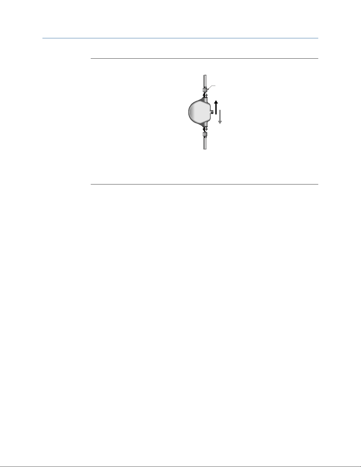
2.2 Best practices
• There are no pipe run requirements for Micro Motion sensors. Straight runs of pipe
upstream or downstream are unnecessary.
• If the sensor is installed in a vertical pipeline, liquids and slurries should flow upward
through the sensor. Gases should flow downward.
• Keep the sensor tubes full of process fluid.
• For halting flow through the sensor with a single valve, install the valve downstream
from the sensor.
8 Micro Motion ELITE
Page 9

Installation Manual
20002158 June 2022
• The sensor does not require external supports. The flanges will support the sensor in
any orientation. (Some sensor models installed in very small, flexible pipeline have
optional installation instructions that allow for external supports.)
Planning
2.2.1 High temperature best practices
• Perform steam injection downstream of the Coriolis meter
• Use steam traps to eliminate condensation and steam flashing
• Control fast acting valves to prevent hammer shock
• Install the meter symmetrically (not tilted)
• Use heat jacket symmetrically (avoid electric or oil trace on just one side)
• To avoid plugging for plugging prone applications, apply heat slowly and uniformly
during startup
• Perform slow and controlled switch-over from ethane to de-coking process
For more information, refer to the Micro Motion High Temperature Solutions Best
Practices Guide.
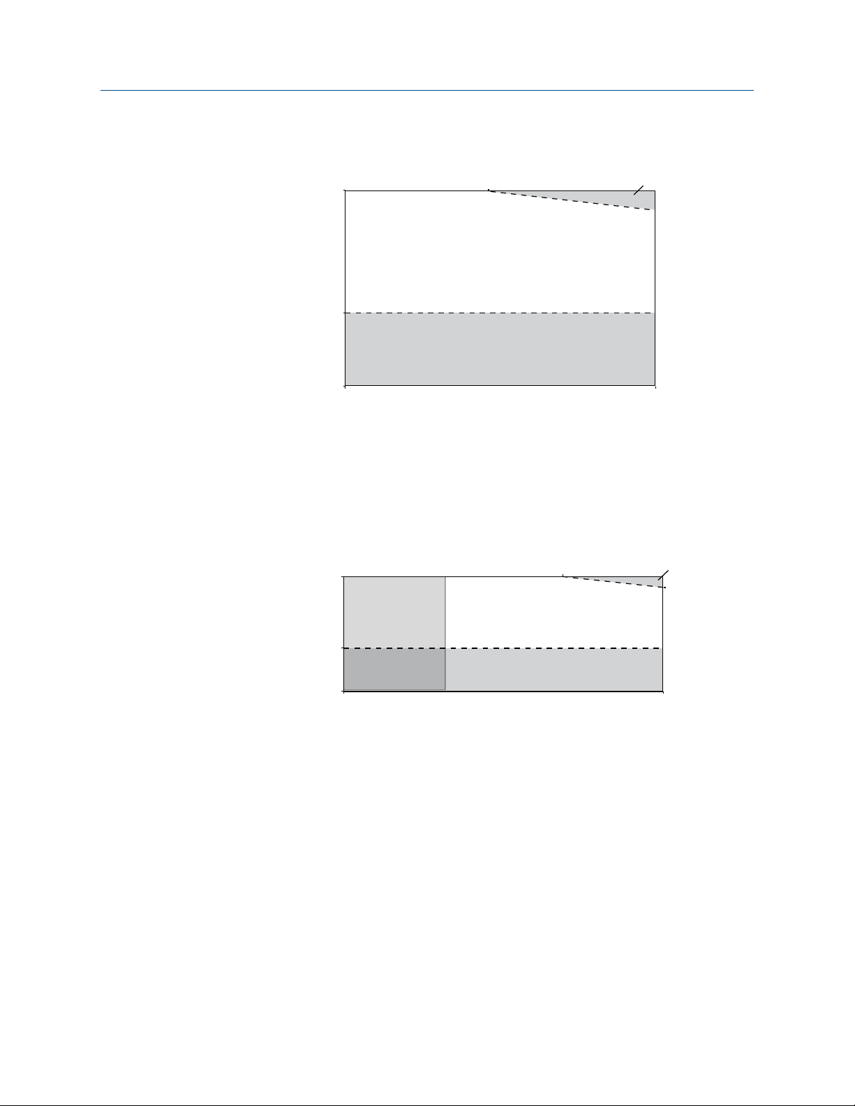
2.3 Temperature limits
Sensors can be used in the process and ambient temperature ranges shown in the
temperature limit graphs. For the purposes of selecting electronics options, temperature
limit graphs should be used only as a general guide. If your process conditions are close to
the gray area, consult with your Micro Motion representative.
WARNING
Temperature limits may be further restricted by hazardous area approvals that are
necessary to avoid potential injury to personnel and damage to equipment. Refer to the
hazardous area approvals documentation shipped with the sensor or available at
www.emerson.com/flowmeasurement for specific temperature ratings for each model
and configuration.
Note
• In all cases, the electronics cannot be operated where the ambient temperature is
below -40 °F (-40 °C) or above 140 °F (60 °C). If a sensor is to be used where the ambient
temperature is outside of the range permissible for the electronics, the electronics
must be remotely located where the ambient temperature is within the permissible
range, as indicated by the shaded areas of the temperature limit graphs.
• The extended-mount electronics option allows the sensor case to be insulated without
covering the transmitter, core processor, or junction box, but does not affect
temperature ratings. When insulating the sensor case at elevated process
temperatures above 140 °F (60 °C), ensure electronics are not enclosed in insulation as
this may lead to electronics failure.
• For the CMFS007 sensor, the difference between the process fluid temperature and the
average temperature of the case must be less than 210 °F (99 °C)
Installation Manual 9
Page 10
140 (60)
–40 (–40)
113
(45)
–148 (–100)
–400
(–240)
400
(204)
140
(60)
T amb
T proc
A
B
B
C
-148
(-100)
Planning Installation Manual
June 2022 20002158
Ambient and process temperature limits for CMFS007, CMFS025–CMFS150
B
113
(45)
Tamb
–40 (–40)
140 (60)
140 (60)
A
B
–148 (–100)
–58 (–50) 400 (204)
T
= Ambient temperature °F (°C)
amb
T
= Process temperature °F (°C)
proc
A = All available electronic options
B= Remote mount electronics only
Ambient and process temperature limits for CMF***M/L/H/P (excludes special order
cryogenic modifications) and CMFS010-015
Tproc
T
= Ambient temperature °F (°C)
amb
T
= Process temperature °F (°C)
proc
A = All available electronic options
B = Remote mount electronics only
C = Recommend special order cryogenic sensor options when operating at a process
temperature below -148 °F (-100 °C)
10 Micro Motion ELITE
Page 11

Installation Manual Planning
20002158 June 2022
Ambient and process temperature limits for special order cryogenic ELITE meters
140 (60)
Tamb
–40 (–40)
A
B
–148 (–100)
–400
(–240)
T
= Ambient temperature °F (°C)
amb
T
= Process temperature °F (°C)
proc
Tproc
A = All available electronic options
B= Remote mount electronics only
Ambient and process temperature limits for high temperature ELITE meters
140 (60)
176
(80)
Tamb
–40 (–40)
–148 (–100)
T
= Ambient temperature °F (°C)
amb
T
= Process temperature °F (°C)
proc
A = All available electronic options
B= Remote mount electronics only
–58
(–50)
A
B
Tproc
662
(350)
Installation Manual 11
Page 12

Planning Installation Manual
June 2022 20002158
Ambient and process temperature limits for super duplex ELITE meters
140 (60)
140 (60)
B
113
(45)
Tamb
–40 (–40)
–148 (–100)
–40 (–40) 400 (204)
T
= Ambient temperature °F (°C)
amb
T
= Process temperature °F (°C)
proc
A
B
Tproc
A = All available electronic options
B= Remote mount electronics only
Note
For super duplex models operating above 351 °F (177.2 °C), consult the factory before
purchase.
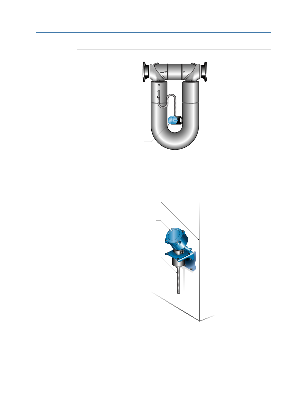
2.4 Recommendations for hygienic and selfdraining applications
CMFS sensors are certified EHEDG TYPE EL CLASS I for hygienic applications when installed
vertically with the process fitting and gasket combinations listed in the Position Paper of
the EHEDG Test Methods Subgroup (available at https://www.ehedg.org). Other process
connections/gasket combinations may be used provided they have been evaluated and
successfully tested for in-place cleanability according to the latest edition of EHEDG
Document 2. Refer to the Micro Motion ELITE Coriolis Flow and Density Meters Product
Data Sheet for further information about fitting options.
For optimal cleanability and drainability:
• If possible, install the sensor in a vertical pipeline with the process fluid flowing upward
through the sensor.
• If the sensor must be installed in a horizontal pipeline, drainage is accomplished by air
purge evacuation of the pipeline circuit.
• For clean-in-place (CIP) applications, Micro Motion recommends using the generally-
accepted flow velocity of at least 1.5 m/s for cleaning the sensor.
• The gap between the electronics housing and sensor body should be inspected
periodically. Manually clean this gap when necessary.
12 Micro Motion ELITE
Page 13
A
B
C
Installation Manual Planning
20002158 June 2022
Figure 2-1: Installation for self-draining applications
A. Process pipeline
B. Direction of normal process flow
C. Direction of drainage
Installation Manual 13
Page 14

Planning Installation Manual
June 2022 20002158
14 Micro Motion ELITE
Page 15

Installation Manual Mounting
20002158 June 2022
3 Mounting
3.1 Recommendations for lifting heavy meters
Heavy meters (those over 50 lb (23 kg)), and even lighter meters that must be installed in
elevated or difficult-to-reach places, usually require additional consideration when
transporting or lifting them into their installation location.
• Safe handling during transportation and installation is the responsibility of the installer.
CAUTION
Know and follow all safety practices and regulations for your facility and for any
lifting/rigging equipment being used in order to prevent injury.
• A professional rigging crew with proper equipment should be used.
• Typical equipment for handling heavy meters includes the following:
— Fixed hoist boom trucks or cranes
— Continuous web belt slings
— Eye to eye web belt slings
— Two leg wire rope slings
• Lift a meter by its case.
• Do not lift a meter by its electronics (junction box, transmitter, or any electrical fittings)
or by its purge fittings.
• It may be useful to identify the meter center of gravity.
• Protect the sealing surfaces on the process fittings with factory-installed flange
protectors or comparable field-installed protection.
Installation Manual 15
Page 16

A
Mounting Installation Manual
June 2022 20002158
Figure 3-1: Acceptable lifting points
Figure 3-2: Center of gravity for large meters
A. Typical center of gravity
Note
Complete and detailed dimensional drawings can be found through the Actions link after a
meter is selected in the online Sizing and Selection tool.
16 Micro Motion ELITE
Page 17

Installation Manual Mounting
20002158 June 2022
3.2 Mount the sensor
NOTICE
• Lifting the sensor by the electronics or purge connections can damage the device.
• To reduce the risk of collecting liquid in the electronics housing, do not orient
transmitters or sensor junction boxes with their conduit openings pointing upward.
Procedure
Mount the sensor.
Notes
• Do not use the sensor to support the piping.
• The sensor does not require external supports. The flanges will support the sensor in
any orientation.Some sensor models installed in small, flexible pipelines have optional
installation instructions that allow for external supports.
Installation Manual 17
Page 18

Mounting Installation Manual
June 2022 20002158
3.3 Rotate junction box or 800 core processor (optional)
An integrally mounted junction box or 800 core processor can be rotated to one of eight
possible positions in 45 degree increments.
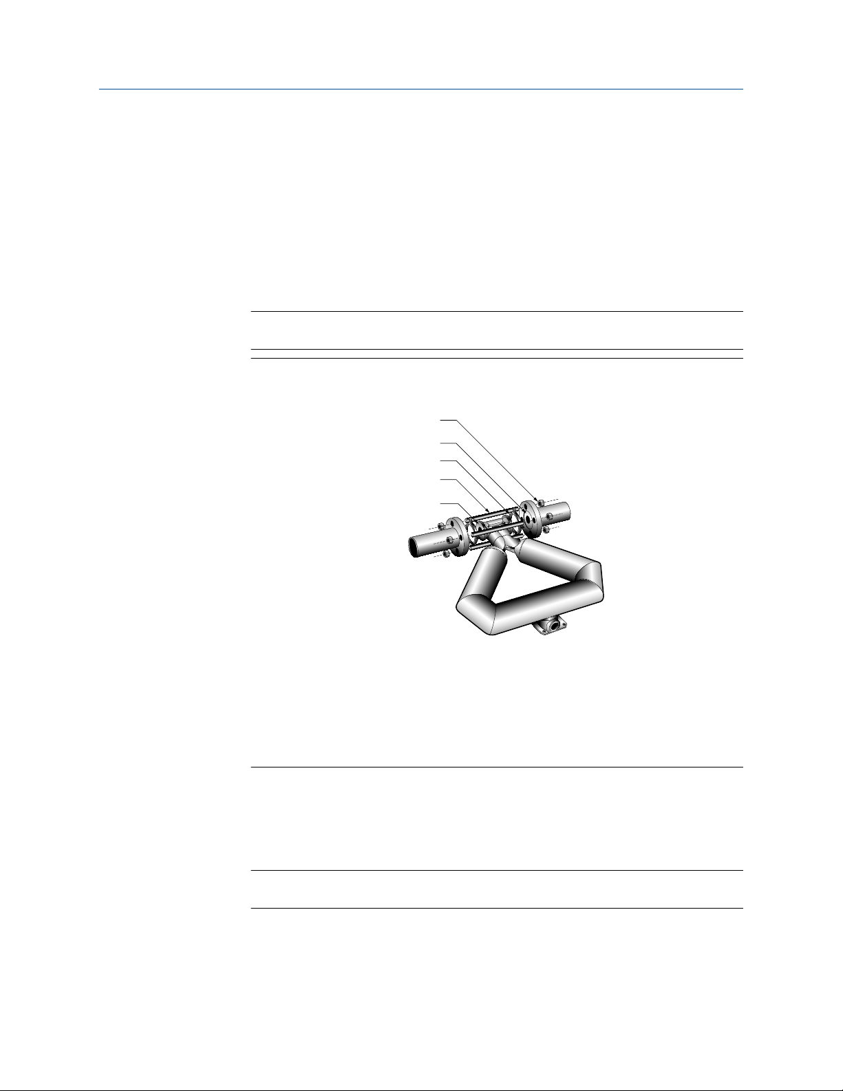
Figure 3-3: Parts for rotating the junction box or 800 core processor on the sensor
A
B
D
C
E
A. Housing
B. Clamping ring
C. Clamping ring screw
D. Feedthrough
E. Alignment notches
Note
The 800 core processor is shown in this figure. The junction box has a somewhat different
appearance.
Procedure
1. Loosen the clamping ring screw and remove the clamping ring.
2. Gently separate the housing from the feedthrough, but only until there is sufficient
clearance from the alignment notches to rotate the housing.
3. Rotate the housing to the desired position and in line with the alignment notches.
4. Seat the housing onto the feedthrough.
5. Replace the clamping ring and tighten the clamping ring screw.
18 Micro Motion ELITE
Page 19

B
A
C
D
Installation Manual Mounting
20002158 June 2022
3.4 Mount electronics of high-temperature sensors
The electronics of high-temperature sensors are attached to the end of a 32 in (813 mm)
pre-installed flexible conduit. The electronics must be separately mounted on a wall or
instrument pole.
Figure 3-4: Components of a high-temperature sensor
A. Sensor
B. Electronics
C. Mounting bracket
D. Flexible conduit with minimum bend radius 6 in (152 mm)
With some large meter sizes, the meter may ship with the electronics attached to the
sensor case. The meter cannot be operated in this configuration. Detach the electronics
bracket from the sensor case and then proceed to mount the electronics to a wall or
instrument pole as described below.
Important
Do not operate the meter while the electronics are attached to the sensor case.
Installation Manual 19
Page 20
A
A
B
C
Mounting
Installation Manual
June 2022 20002158
Figure 3-5: Removing electronics from the sensor case
A. Detach electronics from sensor case and mount to a wall or instrument pole
Procedure
• For wall mounting, use four 0.3 in (8 mm) bolts to secure the mounting bracket.
Figure 3-6: Wall-mount components
A. Wall or flat surface
B. Electronics (enhanced core processor shown)
C. Flexible conduit
20 Micro Motion ELITE
Page 21

A
B
C
Installation Manual Mounting
20002158 June 2022
• For mounting to an instrument pole, use a 2 in (51 mm) U-bolt pipe kit to secure the
mounting bracket.
Figure 3-7: Pole-mount components
A. Instrument pole
B. Electronics (enhanced core processor shown)
C. Flexible conduit
Installation Manual 21
Page 22

A
B
C
Mounting Installation Manual
June 2022 20002158
3.5 Mount a CMF010 sensor to a wall or pole
The CMF010 sensor has an optional mounting configuration for use with small or flexible
pipeline. If the pipeline adequately supports the sensor, you can skip this procedure.
Procedure
1. Locate the optional mounting holes. For sensors with a junction box, the junction
box must be rotated to the side to expose the mounting holes.
Figure 3-8: Optional mounting
A. Two user-supplied 0.3 in (8 mm) bolts
B. Junction box or core processor (junction box shown)
C. Mounting surface
2. If necessary, install rigid standoffs between the sensor and the mounting surface.
3. Using two user-supplied 0.3 in (8 mm) bolts with a minimum length 2.25 in
(57 mm), secure the sensor case to the mounting surface.
22 Micro Motion ELITE
Page 23

A
B
C
Installation Manual Mounting
20002158 June 2022
3.6 Mount a CMFS007, CMFS010, or CMFS015 sensor in a bracket
The CMFS007, CMFS010, and CMFS015 sensors have an optional mounting bracket for use
with small or flexible pipeline. If the pipeline adequately supports the sensor, skip this
procedure.
Procedure
1. Secure the mounting bracket to a wall or other flat surface with four user-supplied
0.3 in (8 mm) bolts.
2. Place the sensor into the bracket.
3. Secure the sensor in the bracket with the supplied 0.3 in (8 mm) U-bolts.
Figure 3-9: Mounting bracket for CMFS007, CMFS010, and CMFS015
A. Mounting bracket
B. Mounting holes
C. Supplied U-bolts
Installation Manual 23
Page 24
Mounting Installation Manual
June 2022 20002158
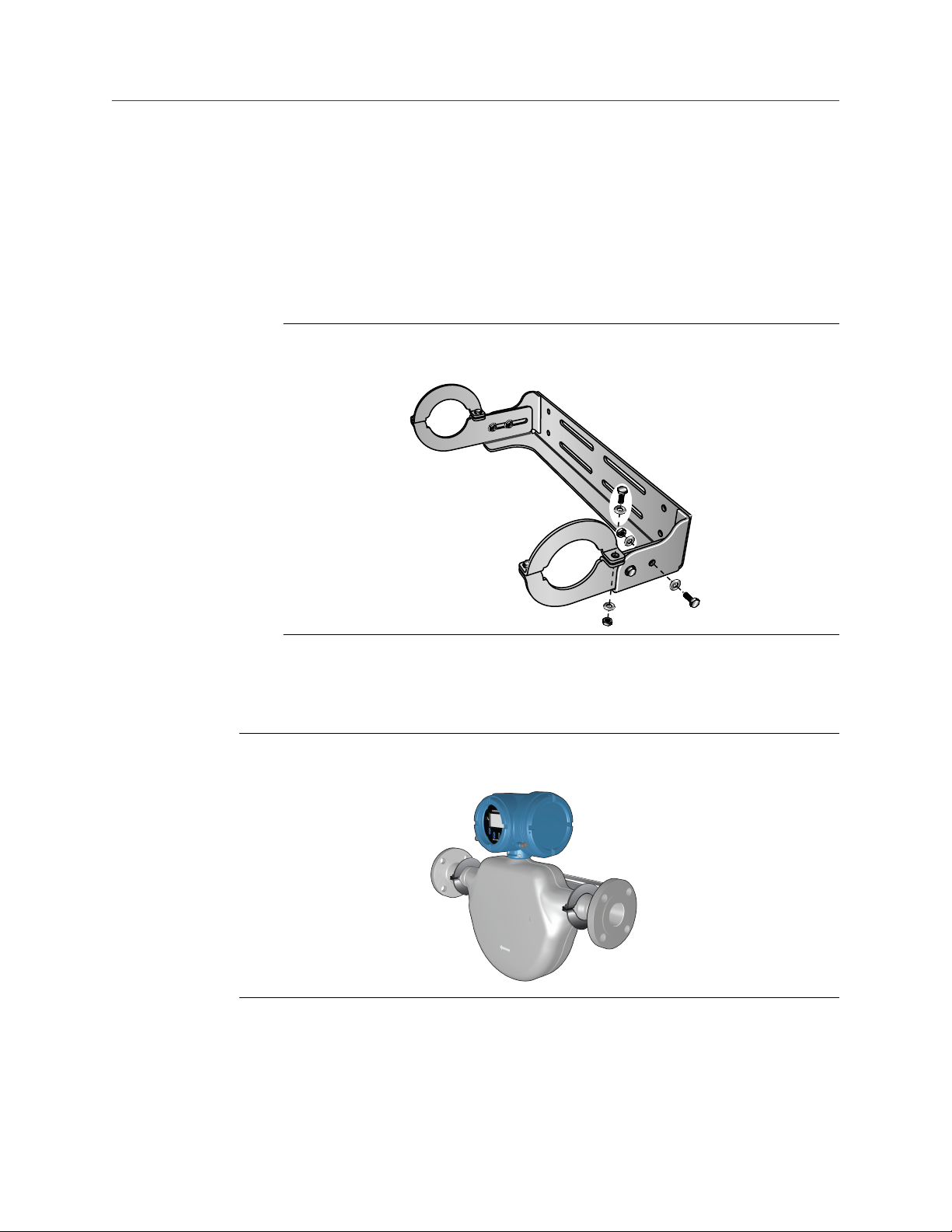
3.7 Mount a CMFS025, CMFS040, or CMFS050 sensor in a wall mount bracket
The CMFS025, CMFS040, and CMFS050 sensors have an optional wall mounting bracket.
Procedure
1. Assemble the bracket.
Figure 3-10: Assembled wall mounting bracket for CMFS025, CMFS040, and
CMFS050
2. Attach the bracket to the wall using fasteners appropriate for the mounting surface.
3. Place the sensor into the bracket.
4. Secure the sensor in the bracket with the supplied fasteners.
Figure 3-11: CMFS025, CMFS040, or CMFS050 wall mounted using bracket
24 Micro Motion ELITE
Page 25
D
C
B
A
E
Installation Manual Mounting
20002158 June 2022
3.8 Secure wafer-style process connections
A wafer-style connection lets you clamp the sensor into the pipeline. A wafer installation
kit is shipped with a wafer-style sensor.
Procedure
1. Make sure that the bolts provided are rated for your process connection.
2. Slip the sensor alignment rings over each end of the sensor wafer; then insert the
sensor between the process connections in the pipeline.
Tip
Micro Motion recommends installing gaskets (user-supplied).
Figure 3-12: Wafer-style connection components
A. Flange nut
B. Gasket (user-supplied)
C. Alignment ring
D. Flange bolt
E. Sensor wafer
3. Insert the flange bolts through both process connections and thread the flange nuts
onto the bolts.
4. With your fingers, tighten the flange nuts.
Installation Manual 25
5. Rotate the sensor alignment rings in the direction that pushes the bolts outward.
Tip
Rotate both sensor alignment rings until the assembly is centered and tight.
Page 26

C
B
A
Mounting Installation Manual
June 2022 20002158
Figure 3-13: Alignment ring usage
A. Direction to rotate the alignment ring
B. Direction the flange bolts are pushed
C. Flange bolt
6. With a wrench, tighten the nuts in an alternating order.
3.9 Attach extended electronics
If your installation has a sensor with extended electronics, you will need to install the
extender onto the sensor case.
Extended core processors are matched at the factory to specific sensors. Keep each core
processor together with the sensor with which it was shipped.
NOTICE
Keep the extender and feedthrough clean and dry. Moisture or debris in the extender or
feedthrough can damage electronics and result in measurement error or flowmeter
failure.
Procedure
1. Remove and recycle the plastic cap from the feedthrough on the sensor.
26 Micro Motion ELITE
Page 27

G
H
E
D
C
A
B
F
Installation Manual Mounting
20002158 June 2022
Figure 3-14: Feedthrough and extender components
A. Transmitter or core processor
B. Extender
C. O-ring
D. Feedthrough
E. Clamping ring
F. Clamping screw
G. Plastic plug
H. Plastic cap
2. Loosen the clamping screw and remove the clamping ring. Leave the O-ring in place
on the feedthrough.
3. Remove and recycle the plastic plug from the extender.
4. Fit the extender onto the feedthrough by carefully aligning the notches on the
bottom of the extender with the notches on the feedthrough.
5. Close the clamping ring and tighten the clamping screw to 13 in lbf (1.47 N m) to
18 in lbf (2.03 N m).
Installation Manual 27
Page 28

Mounting Installation Manual
June 2022 20002158
28 Micro Motion ELITE
Page 29

Installation Manual Transmitter power and I/O wiring
20002158 June 2022
4 Transmitter power and I/O wiring
4.1 Options for wiring
The wiring procedure you follow depends on which electronics option you have.
Table 4-1: Wiring procedures by electronics option
Electronics option Wiring procedure
Integral transmitter The transmitter is already connected to the sensor. No wiring is
required between sensor and transmitter. See the transmitter
installation manual for wiring the power and signal cable to the
transmitter.
Extended electronics The electronics are separated from the sensor by an extender and
must be attached as described in Attach extended electronics.
There is no wiring required because the physical connection
includes the electrical connection.
MVD™ Direct Connect
™
There is no transmitter to wire. See the Micro Motion MVD Direct
Connect Meters Installation ManualMicro Motion MVD Direct
Connect Meters manual for wiring the power and signal cable
between the sensor and the direct host.
Integral core processor with
remote transmitter
Remote core processor
attached to transmitter
Remote core processor
separate from transmitter –
double-hop
WARNING
The core processor is already connected to the sensor. Connect a
4-wire cable between the core processor and transmitter. Refer
to Connect 4-wire cable.
Connect a 9-wire cable between the sensor and the transmitter/
core processor. Refer to Connect the 9-wire cable , as well as the
Micro Motion 9-Wire Flowmeter Cable Preparation and
Installation Manual.
• Connect a 4-wire cable between the core processor and
transmitter. Refer to Connect 4-wire cable.
• Connect a 9-wire cable between the sensor and the core
processor. Refer to Connect the 9-wire cable , as well as the
Micro Motion 9-Wire Flowmeter Cable Preparation and
Installation Manual.
Make sure the hazardous area specified on the sensor approval tag is suitable for the
environment in which the sensor will be installed. Failure to comply with the
requirements for intrinsic safety in a hazardous area could result in an explosion
resulting in injury or death.
NOTICE
Fully close and tighten all housing covers and conduit openings. Improperly sealed
housings can expose electronics to moisture, which can cause measurement error or
flowmeter failure. Inspect and grease all gaskets and O-rings.
Installation Manual 29
Page 30

Transmitter power and I/O wiring Installation Manual
June 2022 20002158
4.2 Connect 4-wire cable
4.2.1 4-wire cable types and usage
Micro Motion offers two types of 4-wire cable: shielded and armored. Both types contain
shield drain wires.
The cable supplied by Micro Motion consists of one pair of red and black 18 AWG
(0.823 mm²) wires for the VDC connection, and one pair of white and green 22 AWG
(0.326 mm²) wires for the RS-485 connection.
User-supplied cable must meet the following requirements:
• Twisted pair construction.
• Applicable hazardous area requirements, if the core processor is installed in a
hazardous area.
• Wire gauge appropriate for the cable length between the core processor and the
transmitter, or the host.
Wire gauge Maximum cable length
VDC 22 AWG (0.326 mm²) 300 ft (91 m)
VDC 20 AWG (0.518 mm²) 500 ft (152 m)
VDC 18 AWG (0.823 mm²) 1,000 ft (305 m)
RS-485 22 AWG (0.326 mm²) or larger 1,000 ft (305 m)
4.2.2 Prepare a cable with a metal conduit
Procedure
1. Remove the core processor cover using a flat-blade screw driver.
2. Run the conduit to the sensor.
3. Pull the cable through the conduit.
4. Cut the drain wires and let them float at both ends of the conduit.
30 Micro Motion ELITE
Page 31

Installation Manual Transmitter power and I/O wiring
20002158 June 2022
4.2.3 Prepare a cable with user-supplied cable glands
Procedure
1. Remove the core processor cover using a flat-blade screw driver.
2. Pass the wires through the gland nut and gland body.
A. Gland body
B. Gland nut
3. Terminate the RS-485 shield and drain wires to the housing internal grounding
screw.
4. Assemble the gland according to vendor instructions.
4.2.4
Prepare a cable with Micro Motion-supplied cable glands
Procedure
1. Remove the core processor cover using a flat-blade screw driver.
2. Pass the wires through the gland nut and clamping insert.
A. Gland nut
B. Clamping insert
3. Strip the cable jacket.
Option
NPT gland type Strip 4.5 in (114 mm)
M20 gland type Strip 4.25 in (108 mm)
4. Remove the clear wrap and filler material.
5. Strip most of the shielding.
Description
Option
NPT gland type Strip all but 0.75 in (19 mm)
M20 gland type Strip all but 0.5 in (13 mm)
Installation Manual 31
Description
Page 32

Transmitter power and I/O wiring Installation Manual
June 2022 20002158
6. Wrap the drain wires twice around the shield and cut off the excess drain wires.
A. Drain wires wrapped around shield
7. For foil (shielded cable) only:
Note
For braided (armored cable) skip this step and contine to the next step.
Option Description
NPT
gland
type
M20
gland
type
a. Slide the shielded heat shrink over the drain wires. Ensure that the
wires are completely covered.
b. Apply 250 °F (121.1 °C) heat to shrink the tubing. Do not burn the
cable.
c. Position the clamping insert so the interior end is flush with the
braid of the heat shrink.
A. Shielded heat shrink
B. After heat is applied
Trim 0.3 in (8 mm).
A. Trim
8. Assemble the gland by folding the shield or braid back over the clamping insert and
0.125 in (3 mm) past the O-ring.
A. Shield folded back
32 Micro Motion ELITE
Page 33

A
B
D
C
AA
Installation Manual Transmitter power and I/O wiring
20002158 June 2022
9. Install the gland body into the conduit opening on the core processor housing.
10. Insert the wires through the gland body and tighten the gland nut onto the gland
body.
A. Shield folded back
B. Gland body
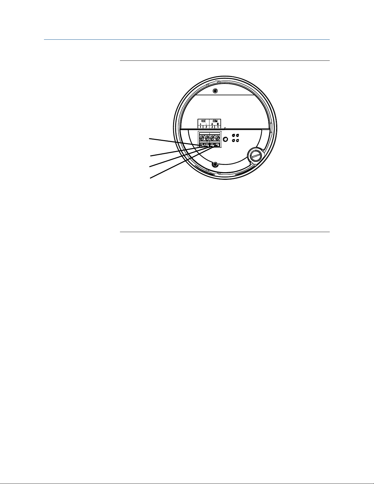
4.2.5 Connect the wires to the core processor terminals
After the 4-wire cable has been prepared and shielded (if required), connect the individual
wires of the 4-wire cable to the terminals on the core processor.
Procedure
1. Connect the wires to the core processor terminals.
• If you are connecting to a standard core processor, use the following image and
connections:
A. Terminal 1 (Power supply +): Red wire
B. Terminal 2 (Power supply -): Black wire
C. Terminal 3 (RS-485/A): White wire
D. Terminal 4 (RS-485/B): Green wire
• If you are connecting to an enhanced core processor, use the Enhanced core
processor and connections:
Installation Manual 33
Page 34
D
A
B
C
Transmitter power and I/O wiring Installation Manual
June 2022 20002158
A. Terminal 1 (Power supply +): Red wire
B. Terminal 2 (Power supply -): Black wire
C. Terminal 3 (RS-485/A): White wire
D. Terminal 4 (RS-485/B): Green wire
2. Reinstall the core processor cover.
3. Torque the cover screws to:
• For aluminum housing: 10 in lbf (1.13 N m) to 13 in lbf (1.47 N m)
• For stainless steel housing: minimum 19 in lbf (2.15 N m)
If properly seated, there will be no gap between cover and base.
4. Connect the wires to the transmitter terminals using the transmitter installation
manual.
34 Micro Motion ELITE
Page 35

Installation Manual Transmitter power and I/O wiring
20002158 June 2022
4.3 Connect the 9-wire cable
Procedure
1. Prepare and install the cable according to the instructions in the Micro Motion 9-
Wire Flowmeter Cable Preparation and Installation Manual.
2. Insert the stripped ends of the individual wires into the terminal blocks of the
junction box.
Ensure that no bare wires remain exposed.
3. Match the wires color for color.
For wiring at the transmitter or remote core processor, refer to the transmitter
documentation.
4. Tighten the screws to hold the wires in place.
5. Ensure integrity of gaskets; then tightly close and seal the junction box cover and all
housing covers.
6. Refer to the transmitter installation manual for signal and power wiring
instructions.
Installation Manual 35
Page 36

Transmitter power and I/O wiring Installation Manual
June 2022 20002158
36 Micro Motion ELITE
Page 37

Installation Manual Grounding
20002158 June 2022
5 Grounding
The meter must be grounded according to the standards that are applicable at the site.
The customer is responsible for knowing and complying with all applicable standards.
Prerequisites
Use the following guides for grounding practices:
• In Europe, IEC 60079-14 is applicable to most installations, in particular sections
16.2.2.3 and 16.2.2.4.
• In the USA and Canada, ISA 12.06.01 Part 1 provides examples with associated
applications and requirements.
If no external standards are applicable, follow these guidelines to ground the sensor:
• Use copper wire, 14 AWG (2.08 mm²) or larger wire size.
• Keep all ground leads as short as possible, less than 1 Ω impedance.
• Connect ground leads directly to earth or follow plant standards.
NOTICE
Ground the flow meter to earth or follow ground network requirements for the facility.
Improper grounding can cause measurement error.
Procedure
• Check the joints in the pipeline.
• If the joints in the pipeline are ground-bonded, the sensor is automatically
grounded and no further action is necessary (unless required by local code).
• If the joints in the pipeline are not grounded, connect a ground wire to the
grounding screw located on the sensor electronics.
Tip
The sensor electronics may be a transmitter, core processor, or junction box. The
grounding screw may be internal or external.
Installation Manual 37
Page 38

Grounding Installation Manual
June 2022 20002158
38 Micro Motion ELITE
Page 39

Installation Manual Supplementary information
20002158 June 2022
6 Supplementary information
6.1 Purge the sensor case
Prerequisites
Make sure the following are available before beginning the purge procedure:
• PTFE™ tape
• Argon or nitrogen gas sufficient to purge the sensor case
If the sensor has purge fittings, they should remain sealed at all times. The sensor is
purged of all oxygen and sealed at the factory. If the purge plugs are never removed, it is
not necessary to purge or re-seal the sensor. For more information, contact customer
support.
Whenever a purge plug is removed from the sensor case, you must purge the case again.
Procedure
1. Shut down the process, or set control devices for manual operation.
NOTICE
Before performing the case purging procedure, shut down the process or set the
control devices for manual operation. Performing the purge procedure while the
flow meter is operating could affect measurement accuracy, resulting in inaccurate
flow signals.
2. Remove both purge plugs from the sensor case. If purge lines are being used, open
the valve in the purge lines.
WARNING
• If a rupture disk has been installed on the purge fitting, stay clear of the
rupture disk pressure relief area. High-pressure fluid escaping from the sensor
can cause severe injury or death. Orient the sensor so that personnel and
equipment will not be exposed to any discharge along the pressure relief path.
• Take all necessary precautions when removing purge plugs. Removing a purge
plug compromises the secondary containment of the sensor and could expose
the user to process fluid.
• Improper pressurization of the sensor case could result in injury.
NOTICE
If a rupture disk has been installed on the purge fitting, use thread protectors when
removing the purge fitting so as not to damage the disk membrane surrounding
the rupture disk.
3. Prepare the purge plugs for reinstallation by wrapping them with 2–3 turns of PTFE
tape.
Installation Manual 39
Page 40

Supplementary information Installation Manual
June 2022 20002158
4. Connect the supply of nitrogen or argon gas to the inlet purge connection or open
inlet purge line. Leave the outlet connection open.
NOTICE
• Exercise caution to avoid introducing dirt, moisture, rust, or other contaminants
into the sensor case.
• If the purge gas is heavier than air (such as argon), locate the inlet lower than the
outlet, so that the purge gas will displace air from bottom to top.
• If the purge gas is lighter than air (such as nitrogen), locate the inlet higher than
the outlet, so that the purge gas will displace air from top to bottom.
5. Make sure that there is a tight seal between the inlet connection and sensor case, so
that air cannot be drawn by suction into the case or purge line during the purging
process.
6. Run purge gas through the sensor.
The purge time is the amount of time required for full exchange of atmosphere to
inert gas. The larger the line size, the greater amount of time is required to purge
the case. If purge lines are being used, increase the purge time to fill the additional
volume of the purge line.
Important
Keep the purge gas pressure below 7.25 psi (0.5 bar).
Table 6-1: Purge time
Sensor model Purge rate Time, in minutes
CMF010 20 ft3/h (566.3 l/h) 1
CMF025 20 ft3/h (566.3 l/h) 1
CMF050 20 ft3/h (566.3 l/h) 2
CMF100 20 ft3/h (566.3 l/h) 5
CMF200 20 ft3/h (566.3 l/h) 12
CMF300 20 ft3/h (566.3 l/h) 30
CMF350 20 ft3/h (566.3 l/h) 45
CMF400 20 ft3/h (566.3 l/h) 55
CMFHC2 20 ft3/h (566.3 l/h) 100
CMFHC3 20 ft3/h (566.3 l/h) 170
CMFHC4 20 ft3/h (566.3 l/h) 268
CMFS007 20 ft3/h (566.3 l/h) 1½
CMFS010 20 ft3/h (566.3 l/h) 1½
CMFS015 20 ft3/h (566.3 l/h) 1½
CMFS025 20 ft3/h (566.3 l/h) 4½
CMFS040 20 ft3/h (566.3 l/h) 4½
CMFS050 20 ft3/h (566.3 l/h) 4½
40 Micro Motion ELITE
Page 41
Installation Manual Supplementary information
20002158 June 2022
Table 6-1: Purge time (continued)
Sensor model Purge rate Time, in minutes
CMFS075 20 ft3/h (566.3 l/h) 6
CMFS100 20 ft3/h (566.3 l/h) 6
CMFS150 20 ft3/h (566.3 l/h) 6
7. At the appropriate time, shut off the gas supply; then immediately seal the purge
outlet and inlet connections with the purge plugs.
Avoid pressurizing the sensor case. If pressure inside the case elevates above
atmospheric pressure during operation, the flow meter density calibration will be
inaccurate.
8. Make sure that the purge fitting seals are tight so that air cannot be drawn by
suction into the sensor case.
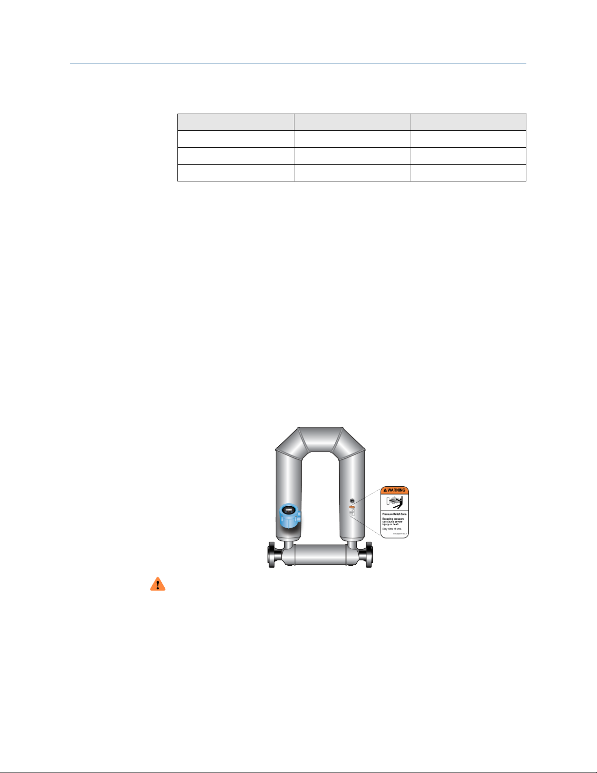
6.2 Pressure relief
ELITE sensors are available with a rupture disk installed on the case. Rupture disks vent
process fluid from the sensor case in the unlikely event of a flow tube breach. Some users
connect a pipeline to the rupture disk to help contain escaping process fluid. For more
information about rupture disks, contact customer service.
If the sensor has a rupture disk, keep it installed at all times, as it would otherwise be
necessary to re-purge the case. If the rupture disk is activated by a tube breach, the seal in
the rupture disk will be broken, and the Coriolis meter should be removed from service.
WARNING
• Orient the sensor so that personnel and equipment will not be exposed to any
discharge along the pressure relief path.
• Stay clear of the rupture disk pressure relief area. High-pressure fluid escaping from
the sensor can cause severe injury or death.
Installation Manual 41
Page 42

Supplementary information Installation Manual
June 2022 20002158
Important
If using a rupture disk, the housing can no longer assume a secondary containment
function.
NOTICE
Removing the purge fitting, blind plug, or rupture disks compromises the Ex-i Safety
Certification, the Ex-tc Safety Certification, and the IP-rating of the Coriolis meter. Any
modification to the purge fitting, blind plug, or rupture disks must maintain a minimum of
IP66/IP67 Ratings.
42 Micro Motion ELITE
Page 43

Installation Manual
20002158 June 2022
Installation Manual 43
Page 44

*20002158*
20002158
Rev. DP
2022
For more information:
©
2022 Micro Motion, Inc. All rights reserved.
The Emerson logo is a trademark and service mark of Emerson
Electric Co. Micro Motion, ELITE, ProLink, MVD and MVD Direct
Connect marks are marks of one of the Emerson Automation
Solutions family of companies. All other marks are property of
their respective owners.
www.emerson.com
 Loading...