


Installation Manual
MMI-20058013, Rev AC
Micro Motion™ 4200 2-Wire Transmitter
April 2022

Safety messages
Safety messages are provided throughout this manual to protect personnel and equipment. Read each safety message carefully
before proceeding to the next step.
Safety and approval information
This Micro Motion product complies with all applicable European directives when properly installed in accordance with the
instructions in this manual. Refer to the EU declaration of conformity for directives that apply to this product. The following are
available: the EU declaration of conformity, with all applicable European directives, and the complete ATEX Installation Drawings
and Instructions. In addition the IECEx Installation Instructions for installations outside of the European Union and the CSA
Installation Instructions for installations in North America are available on the internet at www.emerson.com or through your local
Micro Motion support center.
Information affixed to equipment that complies with the Pressure Equipment Directive, can be found on the internet at
www.emerson.com. For hazardous installations in Europe, refer to standard EN 60079-14 if national standards do not apply.
Other information
Full product specifications can be found in the product data sheet. Troubleshooting information can be found in the configuration
manual. Product data sheets and manuals are available from the Micro Motion web site at www.emerson.com.
Return policy
Follow Micro Motion procedures when returning equipment. These procedures ensure legal compliance with government
transportation agencies and help provide a safe working environment for Micro Motion employees. Micro Motion will not accept
your returned equipment if you fail to follow Micro Motion procedures.
Return procedures and forms are available on our web support site at www.emerson.com, or by phoning the Micro Motion
Customer Service department.
Emerson Flow customer service
Email:
• Worldwide: flow.support@emerson.com
• Asia-Pacific: APflow.support@emerson.com
2

Installation Manual Contents
MMI-20058013 April 2022
Contents
Chapter 1 Planning.................................................................................................................... 5
1.1 About this document...................................................................................................................5
1.2 Related documentation............................................................................................................... 5
1.3 Meter components...................................................................................................................... 5
1.4 Installation types......................................................................................................................... 5
1.5 Installation checklist.................................................................................................................... 7
1.6 Maximum cable lengths between sensor and transmitter............................................................ 9
Chapter 2 Mounting and sensor wiring.................................................................................... 11
2.1 Mounting and sensor wiring for integral-mount transmitters.....................................................11
2.2 Mount the transmitter to a wall or instrument pole....................................................................11
2.3 Wire the 9-wire remote-mount transmitter to the sensor.......................................................... 14
2.4 Ground the meter components................................................................................................. 16
2.5 Rotating the transmitter on the sensor (optional)...................................................................... 17
2.6 Rotating the display orientation.................................................................................................18
2.7 Rotate the sensor wiring junction box on a remote-mount transmitter (optional)......................19
Chapter 3 Wiring the channels................................................................................................. 21
3.1 Installation types for the 4200 transmitter.................................................................................21
3.2 Available channels..................................................................................................................... 22
3.3 Barriers verified by Micro Motion............................................................................................... 23
3.4 Channel power requirements ....................................................................................................23
3.5 Access the wiring channels........................................................................................................ 27
3.6 Wire the Channel A mA HART output.........................................................................................29
3.7 Wire the Channel B mA output...................................................................................................30
3.8 Wire Frequency/Discrete output (Channel B).............................................................................30
3.9 Wire the mA/SIL output............................................................................................................. 31
Chapter 4 Power up the transmitter.........................................................................................33
Chapter 5 Configuring the transmitter with Guided Setup........................................................35
Chapter 6 Using the display controls........................................................................................ 37
6.1 Configure the display backlight..................................................................................................38
Chapter 7 Communicating with the transmitter.......................................................................39
Installation Manual 3

Contents Installation Manual
April 2022 MMI-20058013
4 Micro Motion 4200 2-Wire Transmitter

Installation Manual Planning
MMI-20058013 April 2022
1 Planning
1.1 About this document
This manual provides information on planning, mounting, wiring, and initial setup of the
4200 transmitter. For information on full configuration, maintenance, troubleshooting, or
service of the transmitter, see the configuration and use manual.
The information in this document assumes that users understand basic transmitter and
sensor installation, configuration, and maintenance concepts and procedures.
1.2 Related documentation
See the approval documentation shipped with the transmitter, or download the
appropriate documentation from the Micro Motion web site (www.emerson.com/
flowmeasurement):
• Micro Motion 4200 2-Wire Transmitter: Configuration and Use Manual
• Micro Motion 4200 2-Wire Transmitter: Product Data Sheet
• Micro Motion 4200 2-Wire Transmitter: Safety Manual for Safety Instrumented Systems
• Micro Motion ProLink III with ProcessViz Software User Manual
• Replacing the Junction Box for the 4200 Transmitter and the 5700 Transmitter
• Replacing the Sensor Cable for the 4200 Transmitter and the 5700 Transmitter
• Sensor installation manual, which is shipped with the sensor
• FMEDA report for Coriolis Flowmeter with 4200 Transmitter, Prepared for Emerson by
exida.com LLC
1.3 Meter components
A 4200 meter consists of the following components:
• A transmitter
• A sensor
1.4 Installation types
The 4200 transmitter was ordered and shipped for one of two installation types. The fifth
character of the transmitter number indicates the installation type.
Installation Manual 5

Planning
Installation Manual
April 2022 MMI-20058013
Figure 1-1: Installation type indication for 4200 transmitters
The number is located on the device tag on the side of the transmitter.
Table 1-1: Installation types for 4200 transmitters
Code Description
I Integral mount
C Remote mount
Figure 1-2: 4200 transmitter painted aluminum -- Integral mount
A. Conduit openings
B. Clamping ring
C. Sensor case
D. Transmitter housing cover (hidden from view)
The transmitter is installed directly on the sensor.
The connections between the transmitter and sensor are 9-wire, and do not require field
wiring on the integral mount version.
6 Micro Motion 4200 2-Wire Transmitter

Installation Manual
MMI-20058013 April 2022
The I/O connections consist of two channels, each channel being 2-wire. Power must be
supplied to Channel A for the transmitter to operate, while Channel B connections are
optional.
Figure 1-3: 4200 transmitter -- Remote mount painted aluminum
Planning
A. Transmitter housing cover
B. Clamping ring
C. Junction box
The transmitter is installed remotely from the sensor. The 9-wire connection between the
sensor and transmitter must be field wired. Power supply and I/O must be field wired to
the transmitter. The sensor connection is in the junction box.
1.5 Installation checklist
□ Safety messages are provided throughout this content to protect personnel and
equipment. Read each safety message carefully before proceeding to the next step.
□ When choosing a location for components, refer to the following guidelines:
— See the sensor installation manual for information on locating the sensor with
remote-mount or extended-mount electronics.
— Do not install a component in a location where its temperature, humidity, or
vibration limits will be exceeded.
Installation Manual 7

Planning
April 2022 MMI-20058013
— Maximum distance between components depends on the wire size, the wire type,
and the power supply. Ensure that sufficient power is supplied to the transmitter
terminals.
Installation Manual
□ If you plan to mount the transmitter in a hazardous area:
— Verify that the transmitter has the appropriate hazardous area approval. Each
transmitter has a hazardous area approval tag attached to the transmitter housing.
— Ensure that any cable used between the transmitter and the sensor meets the
hazardous area requirements.
— For ATEX/IECEx installations, you must strictly adhere to the safety instructions
documented in the ATEX/IECEx approvals documentation available on the product
documentation DVD shipped with the product or at www.emerson.com/
flowmeasurement.
□ Verify that you have the appropriate cable and required cable installation parts for your
installation. For wiring between the transmitter and sensor, verify the maximum cable
length does not exceed 60 ft (20 m).
□ The transmitter can be mounted in any orientation as long as the conduit openings do
not point upward.
CAUTION
Installing the transmitter with the conduit openings or transmitter display facing
upward risks condensation moisture entering the transmitter housing, which could
damage the transmitter.
□ To prevent conduit connectors from seizing in the threads of the conduit openings,
apply a conductive anti-galling compound to the threads, or wrap threads with PTFE
tape two to three layers deep. Wrap the tape in the opposite direction that the male
threads will turn when inserted into the female conduit opening.
□ Minimize the amount of moisture or condensation inside the transmitter housing.
Moisture inside the transmitter housing can damage the transmitter and cause
measurement error or flowmeter failure. To do this:
— Ensure the integrity of all gaskets and O-rings
— Install drip legs on conduit or cable
— Seal unused conduit openings
— Ensure that all covers are fully tightened
□ Mount the meter in a location and orientation that satisfies the following conditions:
— Allows sufficient clearance to open the transmitter housing cover. Install with 8–10
inches (200–250 mm) clearance at the wiring access points.
— Provides clear access for installing cabling to the transmitter.
— Provides clear access to all wiring terminals for troubleshooting.
8 Micro Motion 4200 2-Wire Transmitter

Installation Manual Planning
MMI-20058013 April 2022
1.6 Maximum cable lengths between sensor and transmitter
The maximum cable length between the sensor and transmitter that are separately
installed is determined by cable type.
Cable type Wire gauge Maximum length
Micro Motion 9-wire remote
mount
Not applicable 60 ft (18 m)
Installation Manual 9

Planning Installation Manual
April 2022 MMI-20058013
10 Micro Motion 4200 2-Wire Transmitter

Installation Manual Mounting and sensor wiring
MMI-20058013 April 2022
2 Mounting and sensor wiring
2.1 Mounting and sensor wiring for integralmount transmitters
There are no separate mounting requirements for integral transmitters, and no need to
connect wiring between the transmitter and the sensor.
2.2 Mount the transmitter to a wall or instrument pole
There are two options available for mounting the transmitter:
• Mount the transmitter to a wall or flat surface.
• Mount the transmitter to an instrument pole.
Prerequisites
• If you are mounting the transmitter to a wall or flat surface:
— Ensure that the surface is flat and rigid, does not vibrate, or move excessively.
— Confirm that you have the necessary tools, and the mounting kit shipped with the
transmitter.
• If you are mounting the transmitter to an instrument pole:
— Ensure that the instrument pole extends at least 12 in (305 mm) from a rigid base,
and is no more than 2 in (51 mm) in diameter.
— Confirm that you have the necessary tools, and the instrument-pole mounting kit
shipped with the transmitter.
Procedure
1. Attach the mounting bracket to the transmitter and tighten the screws.
Installation Manual 11

Mounting and sensor wiring Installation Manual
April 2022 MMI-20058013
Figure 2-1: Mounting bracket to transmitter
2. Using a wall-mount or pole-mount:
• For wall-mount installations, secure the mounting bracket to the prepared
surface.
Figure 2-2: Wall-mounting bracket dimensions
A. 2.8 in (71.4 mm)
B. 2.8 in (71.4 mm)
12 Micro Motion 4200 2-Wire Transmitter

Installation Manual Mounting and sensor wiring
MMI-20058013 April 2022
• For pole-mount installations, attach the U-bolt mounting piece to the
instrument pole.
Figure 2-3: Pole-mounting bracket attachment
3. Place and attach the transmitter-mounting bracket to the mounting bracket
secured to the wall or instrument pole.
Installation Manual 13

Mounting and sensor wiring Installation Manual
April 2022 MMI-20058013
Figure 2-4: Attaching and securing painted aluminum transmitter to mounting
bracket
Tip
To ensure the mounting bracket holes are aligned, insert all attachment bolts into
place before tightening.
2.3 Wire the 9-wire remote-mount transmitter to the sensor
Prerequisites
• Prepare 9-wire cable as described in the sensor documentation.
• Connect the cable to the sensor-mounted junction box as described in the sensor
documentation. You can access all product documentation on the documentation
DVD shipped with the product or at www.emerson.com/flowmeasurement.
Procedure
1. Remove the transmitter-to-sensor wiring compartment cover to reveal the terminal
connections.
14 Micro Motion 4200 2-Wire Transmitter

Installation Manual Mounting and sensor wiring
MMI-20058013 April 2022
Figure 2-5: Removal of the transmitter-to-sensor wiring compartment cover
2. Feed the sensor wiring cable into the transmitter wiring compartment.
Figure 2-6: Sensor wiring feedthrough
3. Connect the sensor wires to the appropriate terminals:
Installation Manual 15

Mounting and sensor wiring Installation Manual
April 2022 MMI-20058013
Figure 2-7: 9-wire transmitter-to-sensor wiring connections
Note
Connect the 4 drain wires in the 9-wire cable to the ground screw located inside the junction box.
4. Replace the transmitter-to-sensor wiring compartment cover and tighten the
screws to 14-16 in-lbs.
2.4 Ground the meter components
In 9-wire remote installations, the transmitter and sensor are grounded separately.
Prerequisites
NOTICE
Improper grounding could cause inaccurate measurements or meter failure.
WARNING
Failure to comply with requirements for intrinsic safety in a hazardous area could result
in an explosion causing death or serious injury.
Note
For hazardous area installations in Europe, refer to standard EN 60079-14 or national
standards.
If national standards are not in effect, adhere to the following guidelines for grounding:
• Use copper wire, 14 AWG (2.08 mm2) or larger wire size.
16 Micro Motion 4200 2-Wire Transmitter

Installation Manual Mounting and sensor wiring
MMI-20058013 April 2022
• Keep all ground leads as short as possible, less than 1 Ω impedance.
• Connect ground leads directly to earth, or follow plant standards.
Procedure
1. Ground the sensor according to the instructions in the sensor documentation.
2. Ground the transmitter according to applicable local standards, using the
transmitter’s internal or external ground screw.
• The earth ground terminal is located inside the power wiring compartment.
• The external ground screw is located on the side of the transmitter located
below the transmitter tag.
2.5 Rotating the transmitter on the sensor (optional)
For easier access to the user interface or the wiring terminals, the transmitter can be
rotated on the sensor in 45° increments, for eight different orientations.
Figure 2-8: Rotating the transmitter on the sensor
A. Clamping ring
Procedure
1. Remove the metal clamping ring from the base of the feed through (refer to Figure
2-8).
Installation Manual 17

Mounting and sensor wiring Installation Manual
April 2022 MMI-20058013
2. Gently lift the transmitter on the feed through until it disengages from the notches
on the feed through. You will not be able to remove the transmitter completely.
3. Rotate the transmitter to the desired position.
CAUTION
Do not rotate the housing more than 360°. Excessive rotation can damage the
wiring and cause measurement error or flowmeter failure.
4. Lower the transmitter, sliding it onto the notches on the feed through.
5. Replace the clamping ring on the feed through. Tighten the screw to 28 in lbf
(3.16 N m)– 32 in lbf (3.62 N m).
CAUTION
Ensure that the connection between the transmitter and the sensor is moistureproof. Inspect and grease all gaskets and O-rings. Moisture in the electronics can
cause measurement error or flowmeter failure.
2.6 Rotating the display orientation
The user interface orientation for the 4200 transmitter can rotate 360° in 90° increments
by software selection.
Using the display, select Menu → Configuration → Display Settings → Rotation.
18 Micro Motion 4200 2-Wire Transmitter

Installation Manual Mounting and sensor wiring
MMI-20058013 April 2022
2.7 Rotate the sensor wiring junction box on a remote-mount transmitter (optional)
In remote-mount installations, you can rotate the sensor wiring junction box on the
transmitter up to plus or minus 180 degrees.
Procedure
1. Using a 4 mm hex key, loosen and remove the clamp securing the sensor wiring
junction box in place.
Figure 2-9: Removal of the clamp
2. Gently rotate the junction box to the desired position.
You can rotate the junction box plus or minus 180º to any position.
Installation Manual 19

Mounting and sensor wiring Installation Manual
April 2022 MMI-20058013
Figure 2-10: Rotation of the sensor wiring junction box
3. Gently set the junction box into its new position, confirming that the position is
locked.
4. Replace the clamp in its original position and tighten the cap screw. Tighten the
screw to 28 in lbf (3.16 N m)– 32 in lbf (3.62 N m).
Figure 2-11: Re-attachment of the clamp
20 Micro Motion 4200 2-Wire Transmitter

Installation Manual Wiring the channels
MMI-20058013 April 2022
3 Wiring the channels
3.1 Installation types for the 4200 transmitter
WARNING
If you are installing the transmitter in a hazardous area, refer to Micro Motion approval
instructions, shipped with the product or available from the Micro Motion web site
(www.emerson.com/flowmeasurement). Improper installation in a hazardous area can
cause an explosion.
General configuration
A. 2-wire cable power and signal
B. 4-20 mA
C. mA receiving device
D. HART® variables
E. DCS
F. Emerson AMS Trex communicator
Installation Manual 21
Wiring the channels Installation Manual
April 2022 MMI-20058013
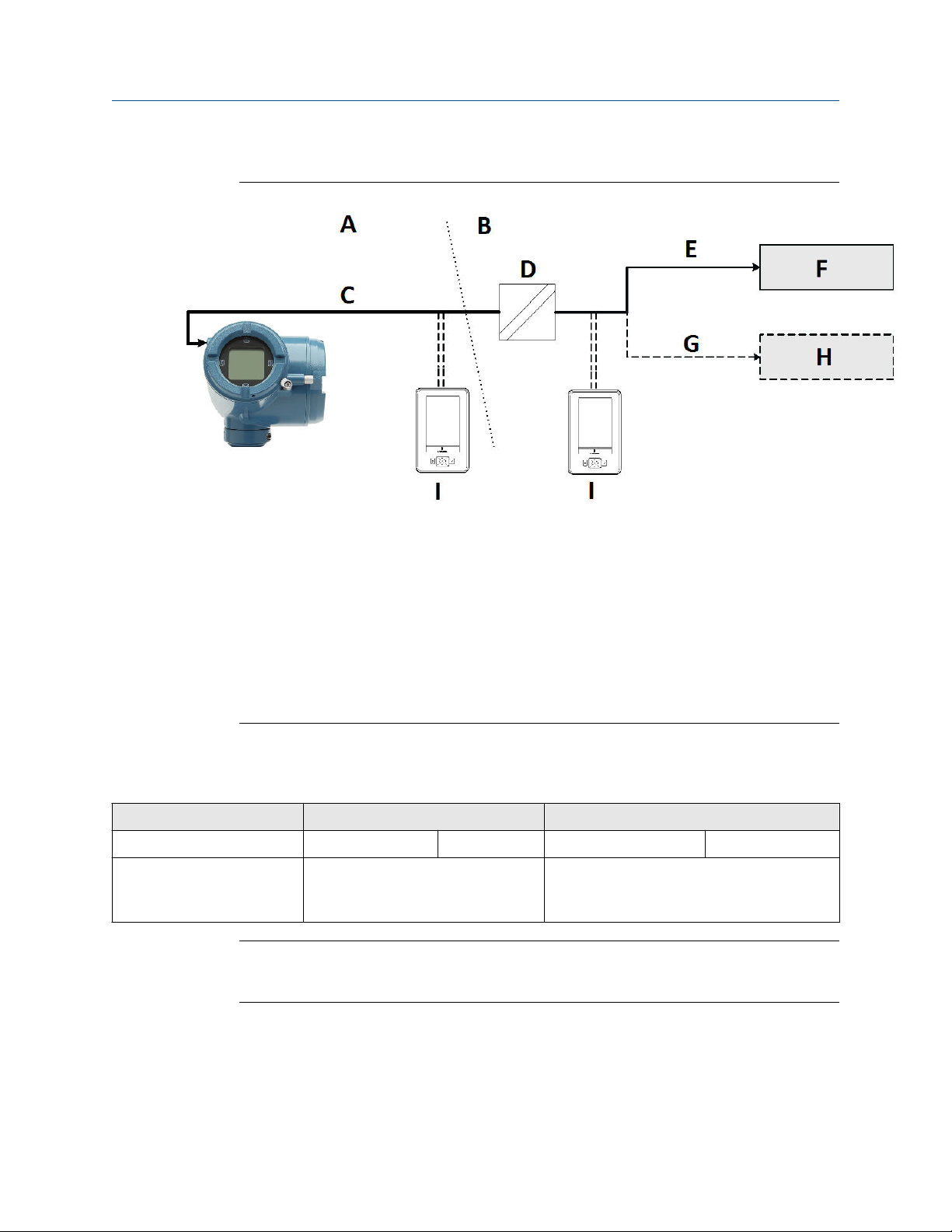
Connection example for cases where a barrier is required
A. Hazardous area
B. Safe area
C. 2-wire cable power and signal
D. Barrier
E. 4-20 mA
F. mA receiving device
G. HART variables
H. DCS
I. Emerson AMS Trex communicator
3.2 Available channels
Signal Channel A Channel B
Wiring terminals 1 2 3 4
mA outputs 4-20mA Loop Powered (HART) (Optional licensed channel)
Configurable as passive 4-20mA / Frequency
Output / Discrete Output
Note
Remember when using the second configurable output (Channel B), all power to the
electronics is still supplied over the primary 4 - 20 mA signal wiring (Channel A).
22 Micro Motion 4200 2-Wire Transmitter

Installation Manual Wiring the channels
MMI-20058013 April 2022
3.3 Barriers verified by Micro Motion
The following table lists the barriers that Micro Motion has verified with the 4200
transmitter. For other barriers, refer to the manufacturer's data sheet.
Table 3-1: Barriers verified by Micro Motion
Vendor Barrier
Micro Motion 505
Pepperl & Fuchs KFD2-STC1-EX1
Pepperl & Fuchs KFD2-STC4-EX1
MTL 787S+
MTL 7707P+
MTL 7787+
MTL 5042
MTL 3046B
MTL 7728P+
MTL 4541
STAHL 9002/13-280-110-00
PR Electronics 5106
3.4 Channel power requirements
The supply voltage required by the 4200 transmitter depends on the total resistance in the
mA loop. This includes all sense resistance and wire resistance.
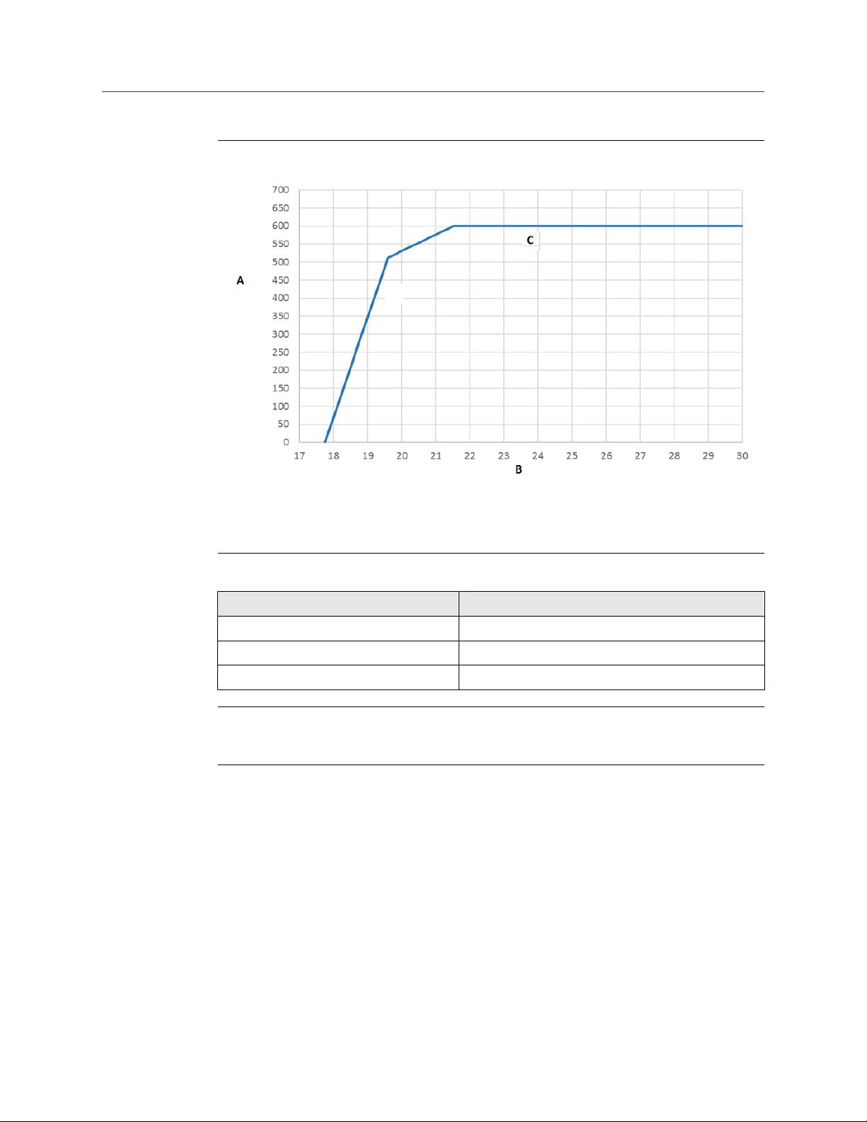
Channel A mA HART terminal requirements
Use the chart below to determine the required supply voltage for Channel A based on loop
resistance.
Installation Manual 23
Wiring the channels Installation Manual
April 2022 MMI-20058013
Figure 3-1: Channel A output supply voltage and loop resistance
A. Loop resistance (Ohms)
B. Supply voltage (Vs)
C. Maximum Loop Resistance (Ohms)
Table 3-2: For maximum loop resistance for Channel A
Condition Equation
17.75V < Vs <19.6V (Vs-17.75)/3.6mA
19.6V < Vs < 21.5V (Vs-8.32V)/22mA
21.5V <Vs <30V 600 ohms
Note
If display backlighting is enabled (refer to Configure the display backlight) , the minimum
input voltage required is 1V higher than the chart indicates.
24 Micro Motion 4200 2-Wire Transmitter
Installation Manual Wiring the channels
MMI-20058013 April 2022
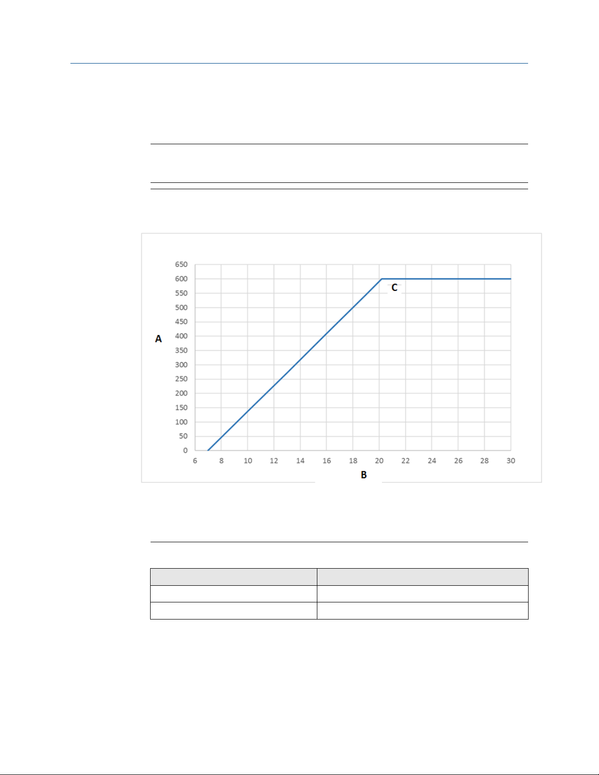
Channel B mA terminal requirements
Use the following chart to determine the required supply voltage for Channel B mA based
on loop resistance.
Note
Remember when using the second configurable output (Channel B), all power to the
electronics is still supplied over the primary 4 - 20 mA signal wiring (Channel A).
Figure 3-2: Channel B output supply voltage and loop resistance
A. Loop resistance (Ohms)
B. Supply voltage (Vs)
C. Maximum Loop Resistance (Ohms)
Table 3-3: For maximum loop resistance for Channel B
Condition Equation
7.0V < Vs <20.2V (Vs-7.0V)/22mA
20.2V < Vs < 30V 600 ohms
Channel B DO/FO terminal requirements
Use the chart below to determine the required supply voltage for Channel B for DO/FO.
Installation Manual 25

Wiring the channels Installation Manual
April 2022 MMI-20058013
Figure 3-3: Channel B FO/DO output supply voltage and loop resistance
A. Loop resistance (Ohms)
B. Supply voltage (Vs)
C. Maximum Loop Resistance (Ohms)
Note
For Maximum Loop Resistance:
• (Vs-6.0V)/3.2mA
26 Micro Motion 4200 2-Wire Transmitter

Installation Manual Wiring the channels
MMI-20058013 April 2022
Channel B DO/FO high and low voltages for nonhazardous installations
Figure 3-4: Output high and low voltages
A. Output voltage (V)
B. Load resistance (Ohm)
C. Low voltage
D. High voltage
E. Voltage (volts)
F. Time
High and low voltage equations
High voltage ≈ (Vsupply – 1.08V) * RL/(1130 + RL)
Low voltage ≈ 0.0002*RL
3.5 Access the wiring channels
Procedure
1. Remove the wiring access cover to reveal the I/O wiring terminal block connectors.
Installation Manual 27

Wiring the channels Installation Manual
April 2022 MMI-20058013
A. Channel A connections
B. Channel B connections
2. Confirm which transmitter channels are activated, or ON, and identify the type of
configuration you will be wiring to based on the options available.
Figure 3-5: Activated channel identification
3. (Recommended) Record the channel and wiring configuration on the label provided
inside the transmitter housing cover.
28 Micro Motion 4200 2-Wire Transmitter

A
1
2
D
C
B
Installation Manual Wiring the channels
MMI-20058013 April 2022
Figure 3-6: Channel and wiring configurations label
3.6 Wire the Channel A mA HART output
To wire the mA/HART output in explosion-proof, intrinsically safe, or nonhazardous
installations, follow this procedure.
WARNING
Meter installation and wiring should be performed only by suitably-trained personnel
using the appropriate government and corporate safety standards.
Procedure
Wire to the appropriate output terminal and pins.
Figure 3-7: Channel A mA/HART output wiring (externally powered)
A. mA HART output
B. Supply Voltage (See Figure 3-1.)
C. Loop Resistance (See Figure 3-1 for maximum loop resistance.)
D. Input device
Installation Manual 29

A
1
2
D
C
B
Wiring the channels Installation Manual
April 2022 MMI-20058013
3.7 Wire the Channel B mA output
To wire the mA output in explosion-proof, intrinsically safe, or nonhazardous installations,
follow this procedure.
WARNING
Meter installation and wiring should be performed only by suitably-trained personnel
using the appropriate government and corporate safety standards.
Note
Remember when using the second configurable output (Channel B), all power to the
electronics is still supplied over the primary 4 - 20 mA signal wiring (Channel A).
Procedure
Wire to the appropriate output terminal and pins.
Figure 3-8: Channel B mA output wiring (externally powered)
A. mA output
B. Supply Voltage (See Figure 3-2.)
C. Loop Resistance (See Figure 3-2 for maximum loop resistance.)
D. Input device
3.8 Wire Frequency/Discrete output (Channel B)
Use this procedure to wire the externally-powered Frequency Output or Discrete Output
for Channel B.
WARNING
Meter installation and wiring should be performed only by suitably-trained personnel
using the appropriate government and corporate safety standards.
Note
Remember when using the second configurable output (Channel B), all power to the
electronics is still supplied over the primary 4 - 20 mA signal wiring (Channel A).
Procedure
Wire to the appropriate output terminal and pins.
30 Micro Motion 4200 2-Wire Transmitter

A
B
E
D
C
Installation Manual Wiring the channels
MMI-20058013 April 2022
Figure 3-9: Discrete Output wiring (externally powered)
A. Frequency/ Discrete Output
B. Channel B
C. Supply Voltage (See Figure 3-3.)
D. Loop Resistance (See Figure 3-3 for maximum loop resistance.)
E. Counter or Discrete Output
3.9 Wire the mA/SIL output
Refer to the Micro Motion 4200 2-Wire Transmitter: Safety Manual for Safety Instrumented
Systems for additional information regarding installation and commissioning that complies
with SIS requirements.
Installation Manual 31

Wiring the channels Installation Manual
April 2022 MMI-20058013
32 Micro Motion 4200 2-Wire Transmitter

Installation Manual Power up the transmitter
MMI-20058013 April 2022
4 Power up the transmitter
The transmitter must be powered up for all configuration and commissioning tasks, or for
process measurement.
Procedure
1. Ensure that all transmitter and sensor covers and seals are closed.
DANGER
To prevent ignition of flammable or combustible atmospheres, ensure that all
covers and seals are tightly closed. For hazardous area installations, applying
power while housing covers are removed or loose can cause an explosion.
2. Turn on the electrical power at the power supply.
The transmitter will automatically perform diagnostic routines. During this period,
the Warming Up alert is active. The diagnostic routines should complete in
approximately 30 seconds.
Postrequisites
Although the sensor is ready to receive process fluid shortly after power-up, the
electronics can take up to 10 minutes to reach thermal equilibrium. Therefore, if this is the
initial startup, or if power has been off long enough to allow components to reach ambient
temperature, allow the electronics to warm up for approximately 10 minutes before
relying on process measurements. During this warm-up period, you may observe minor
measurement instability or inaccuracy.
Installation Manual 33

Power up the transmitter Installation Manual
April 2022 MMI-20058013
34 Micro Motion 4200 2-Wire Transmitter

Installation Manual Configuring the transmitter with Guided Setup
MMI-20058013 April 2022
5 Configuring the transmitter with
Guided Setup
At initial startup of the transmitter, click the right arrow for the Menu option to access
Guided Setup. This tool guides you through basic configuration of the transmitter. The
guided setup allows you to upload configuration files, set the transmitter display options,
configure channels, and review sensor calibration data.
Procedure
To access the guided setup screen from the display main menu, go to: Startup Tasks →
Guided Setup.
Installation Manual 35

Configuring the transmitter with Guided Setup Installation Manual
April 2022 MMI-20058013
36 Micro Motion 4200 2-Wire Transmitter
Installation Manual Using the display controls
MMI-20058013 April 2022
6 Using the display controls
The transmitter display interface includes a display (LCD panel) and four capacitive
buttons – left, up, down, and right arrow keys – used to access the display menus and
navigate the display screens.
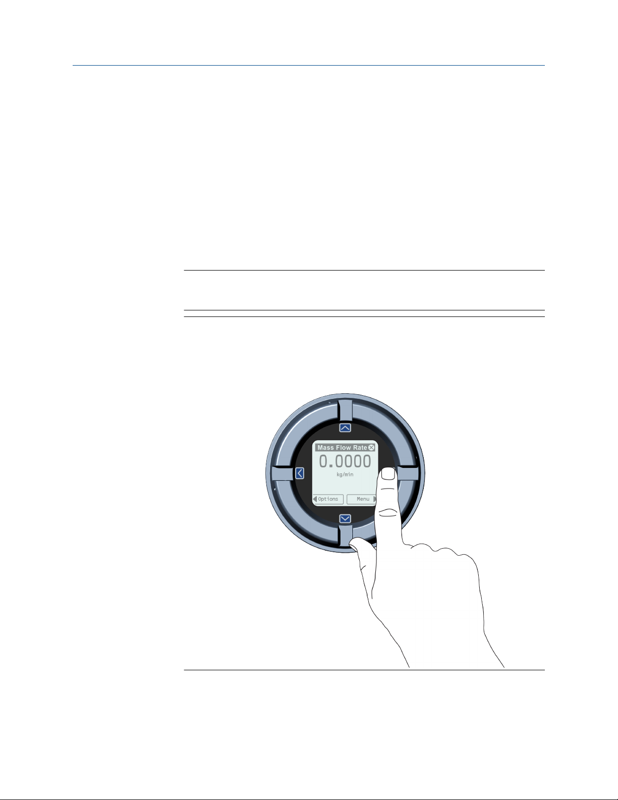
Procedure
1. To activate a capacitive button, press the desired button that is designated with
arrows (up, down, left, and right).
You can activate the capacitive button through the lens. Do not remove the
transmitter housing cover.
Important
The transmitter only detects one button selection at a time. Be sure to press your
thumb or finger on a single capacitive button.
Figure 6-1: Proper finger positioning for activating a capacitive button
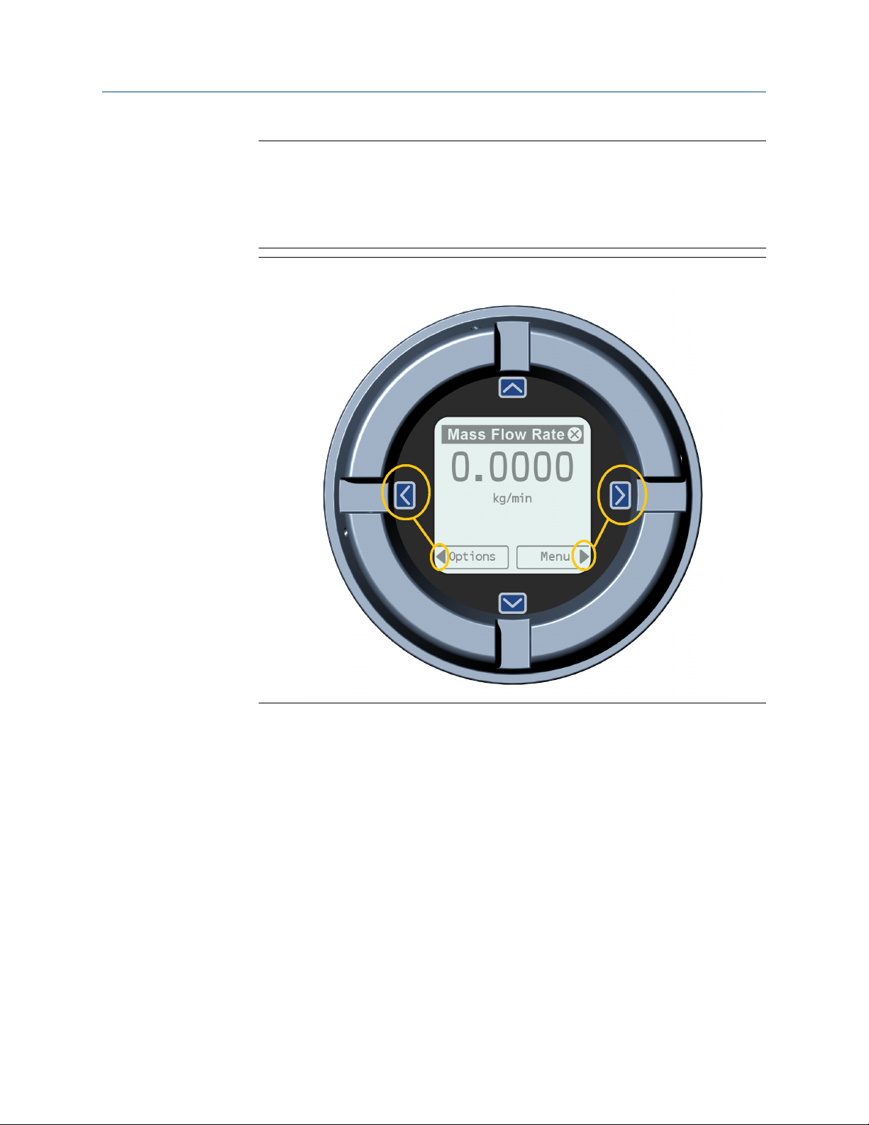
2. Use the arrow indicators on the display screen to identify which capacitive button to
use to navigate the screen (see examples 1 and 2).
Installation Manual 37
Using the display controls Installation Manual
April 2022 MMI-20058013
Important
When using the arrow keys, you must first activate the capacitive button, then
release the same button by removing your finger from the glass to move up, down,
right, left or to make a selection. To enable auto-scroll when navigating up or down,
activate the appropriate button and continue to hold for one second. Release the
button when the desired selection is highlighted.
Figure 6-2: Example 2: Active arrow indicators on the transmitter display
6.1 Configure the display backlight
By default, the backlight is set to OFF. The backlight requires an additional 1V in voltage
over no backlight.
Procedure
To enable the backlight, select Menu → Configuration → Display Settings → Backlight.
38 Micro Motion 4200 2-Wire Transmitter

Installation Manual Communicating with the transmitter
MMI-20058013 April 2022
7 Communicating with the transmitter
Use either the HART terminals connected to ProLink III or a hand-held 475 or Trex unit to
download or upload data from/to the transmitter, because the service port is for factory
use only.
Procedure
1. To connect to the transmitter terminals or to the HART connection posts:
a) Remove the transmitter end-cap.
b) Attach the leads from the Field Communicator to terminals 1 and 2 on the
transmitter, or to the HART connection posts, and add resistance as required.
The Field Communicator must be connected across a resistance of
250–600 Ω.
Tip
HART connections are not polarity-sensitive. It does not matter which lead
you attach to which terminal.
Figure 7-1: Field Communicator connection to transmitter terminals
A. Field Communicator
B. 250–600 Ω resistance
C. External power supply, if required
D. Transmitter with end-cap removed
E. HART connection posts
F. Factory use only
2. Turn on the Field Communicator and wait until the main menu is displayed.
Installation Manual 39

* MMI-20058013*
MMI-20058013
Rev. AC
2022
For more information:
©
2022 Micro Motion, Inc. All rights reserved.
The Emerson logo is a trademark and service mark of Emerson
Electric Co. Micro Motion, ELITE, ProLink, MVD and MVD Direct
Connect marks are marks of one of the Emerson Automation
Solutions family of companies. All other marks are property of
their respective owners.
www.emerson.com
 Loading...