

Page 1
Configuration and Use Manual
Micro Motion™ 2700 Transmitters with
FOUNDATION™ Fieldbus
Configuration and Use Manual
20000326, Rev EE
August 2022
Page 2

Safety messages
Safety messages are provided throughout this manual to protect personnel and equipment. Read each safety message carefully
before proceeding to the next step.
Safety and approval information
This Micro Motion product complies with all applicable European directives when properly installed in accordance with the
instructions in this manual. Refer to the EU declaration of conformity for directives that apply to this product. The following are
available: the EU Declaration of Conformity, with all applicable European directives, and the complete ATEX installation drawings
and instructions. In addition, the IECEx installation instructions for installations outside of the European Union and the CSA
installation instructions for installations in North America are available at Emerson.com or through your local Micro Motion
support center.
Information affixed to equipment that complies with the Pressure Equipment Directive, can be found at Emerson.com. For
hazardous installations in Europe, refer to standard EN 60079-14 if national standards do not apply.
Other information
Troubleshooting information can be found in the Configuration Manual. Product data sheets and manuals are available from the
Micro Motion web site at Emerson.com.
Return policy
Follow Micro Motion procedures when returning equipment. These procedures ensure legal compliance with government
transportation agencies and help provide a safe working environment for Micro Motion employees. Micro Motion will not accept
your returned equipment if you fail to follow Micro Motion procedures.
Return procedures and forms are available on our web support site at Emerson.com, or by calling the Micro Motion Customer
Service department.
2
Page 3

Configuration and Use Manual Contents
20000326 August 2022
Contents
Chapter 1 Before you begin........................................................................................................7
1.1 About this manual....................................................................................................................... 7
1.2 Fieldbus instrument data sheet....................................................................................................7
1.3 Communication methods............................................................................................................8
1.4 Related documentation............................................................................................................... 8
Chapter 2 Quick start................................................................................................................. 9
2.1 Power up the transmitter.............................................................................................................9
2.2 Check meter status......................................................................................................................9
2.3 Determine the FOUNDATION Fieldbus unique device ID................................................................
2.4 Make a startup connection to the transmitter............................................................................10
2.5 Verify mass flow measurement..................................................................................................11
10
Chapter 3 Introduction to configuration and commissioning....................................................13
3.1 Configuration flowchart.............................................................................................................13
3.2 Default values and ranges.......................................................................................................... 14
3.3 Enable access to the off-line menu of the display....................................................................... 14
3.4 Disable write-protection on the transmitter configuration.........................................................14
3.5 Place function, transducer, and resource blocks in OOS mode................................................... 14
3.6 Lockout FOUNDATION Fieldbus hosts............................................................................................15
3.7 Restore the factory configuration.............................................................................................. 15
3.8 Enable or disable fieldbus write lock...........................................................................................15
Chapter 4 Configure process measurement..............................................................................17
4.1 Configure mass flow measurement........................................................................................... 17
4.2 Configure volume flow measurement for liquid applications..................................................... 21
4.3 Configure GSV flow measurement.............................................................................................24
4.4 Configure Flow Direction .......................................................................................................... 28
4.5 Configure density measurement ...............................................................................................30
4.6 Configure temperature measurement....................................................................................... 34
4.7 Configure the petroleum measurement application.................................................................. 36
4.8 Set up concentration measurement ..........................................................................................39
4.9 Set up concentration measurement using a basic FF host.......................................................... 44
4.10 Configure pressure compensation........................................................................................... 46
Chapter 5 Configure device options and preferences................................................................ 51
5.1 Configure the transmitter display.............................................................................................. 51
5.2 Enable or disable operator actions from the display................................................................... 54
5.3 Configure security for the display menus................................................................................... 56
5.4 Configure response time parameters.........................................................................................58
Configuration and Use Manual 3
Page 4

Contents Configuration and Use Manual
August 2022 20000326
5.5 Configure alert handling............................................................................................................ 58
5.6 Configure informational parameters..........................................................................................61
Chapter 6 Complete the configuration..................................................................................... 65
6.1 Back up transmitter configuration............................................................................................. 65
6.2 Return function blocks to In Service (Auto) mode...................................................................... 65
Chapter 7 Transmitter operation..............................................................................................67
7.1 Record the process variables......................................................................................................67
7.2 View process variables............................................................................................................... 67
7.3 View transmitter status using the status LED............................................................................. 69
7.4 View and acknowledge status alerts.......................................................................................... 70
7.5 Read totalizer and inventory values............................................................................................74
7.6 Start and stop totalizers and inventories.................................................................................... 74
7.7 Reset totalizers.......................................................................................................................... 76
7.8 Reset inventories....................................................................................................................... 77
Chapter 8 Measurement support..............................................................................................79
8.1 Options for measurement support.............................................................................................79
8.2 Use Smart Meter Verification..................................................................................................... 79
8.3 Zero the meter.......................................................................................................................... 89
8.4 Validate the meter.....................................................................................................................90
8.5 Perform a (standard) D1 and D2 density calibration...................................................................92
8.6 Perform temperature calibration............................................................................................... 94
Chapter 9 Troubleshooting...................................................................................................... 97
9.1 Density measurement problems................................................................................................97
9.2 Check the drive gain.................................................................................................................. 98
9.3 Check for internal electrical problems........................................................................................99
9.4 Flow measurement problems ..................................................................................................101
9.5 Check grounding..................................................................................................................... 103
9.6 Check the pickoff voltage........................................................................................................ 103
9.7 Check power supply wiring...................................................................................................... 104
9.8 Check for radio frequency interference (RFI)............................................................................ 104
9.9 Check for two-phase flow (slug flow)....................................................................................... 105
9.10 Status alerts, causes, and recommendations......................................................................... 105
9.11 Temperature measurement problems................................................................................... 120
Appendix A Transducer blocks and views.................................................................................. 121
A.1 Descriptions of transducer block table entries......................................................................... 121
A.2 Measurement transducer blocks..............................................................................................123
A.3 Calibration transducer blocks.................................................................................................. 140
A.4 Diagnostics transducer blocks................................................................................................. 151
A.5 Device information transducer blocks..................................................................................... 181
A.6 Local display transducer blocks................................................................................................189
4 Micro Motion 2700 Transmitters with FOUNDATION Fieldbus
Page 5

Configuration and Use Manual Contents
20000326 August 2022
A.7 Petroleum measurement transducer blocks............................................................................ 197
A.8 Concentration measurement transducer blocks...................................................................... 205
A.9 Density viscosity meter transducer blocks............................................................................... 221
Appendix B Fieldbus channel references................................................................................... 257
Appendix C FOUNDATION Fieldbus function blocks................................................................... 261
C.1 Analog Input (AI) function block.............................................................................................. 261
C.2 Analog Output (AO) function block......................................................................................... 266
C.3 Integrator (INT) Function Block................................................................................................269
C.4 Discrete Input (DI) function block............................................................................................ 273
C.5 Discrete Output (DO) function block....................................................................................... 275
Appendix D Using the transmitter display................................................................................. 279
D.1 Using the display..................................................................................................................... 279
Appendix E Using ProLink III with the transmitter..................................................................... 289
E.1 Basic information about ProLink III .......................................................................................... 289
Appendix F Using a field communicator with the transmitter................................................... 291
F.1 Basic information about field communicators.......................................................................... 291
F.2 Connect with the FF host..........................................................................................................291
Appendix G Default values and ranges...................................................................................... 293
G.1 Default values and ranges....................................................................................................... 293
Appendix H Transmitter components and installation wiring....................................................297
H.1 Installation types.....................................................................................................................297
H.2 Power supply terminals and ground ........................................................................................300
H.3 Fieldbus wiring terminals.........................................................................................................301
Appendix I NE53 history...........................................................................................................303
Configuration and Use Manual 5
Page 6

Contents Configuration and Use Manual
August 2022 20000326
6 Micro Motion 2700 Transmitters with FOUNDATION Fieldbus
Page 7

Configuration and Use Manual Before you begin
20000326 August 2022
1 Before you begin
1.1
This manual helps you configure, commission, use, maintain, and troubleshoot Micro Motion 2700
transmitters with FOUNDATION Fieldbus.
Important
This manual assumes that:
• The transmitter has been installed correctly and completely according to the instructions in the
• Users understand basic transmitter and sensor installation, configuration, and maintenance concepts and
About this manual
transmitter installation manual.
procedures.
1.2 Fieldbus instrument data sheet
Transmitter operating conditions
Type Electronic microprocessor based
Input signal FOUNDATION fieldbus H1 ISA.50.02 IEC-61158
Baud rate 31.25 Kbps
Physical media Twisted pair wires, (H1) compliant
Power supply 9–32 VDC, bus powered, 4 wires
Power connections on FF bus 11.5 milliamps maximum
Input voltage Model 2700: 18–100 VDC or 85–265 VAC
Device class Link master; ITK 4.60 minimum
Minimum VCRs 20
Electrical class FISCO; Other
Function blocks
Device function block fixed type FOUNDATION fieldbus FF-891/FF-892 compliant
Analog Input Block (AI) Executable time: 18 ms
Analog Output Block (AO) Executable time: 18 ms
Discrete Input Block Executable time: 16 ms
Discrete Output Block Executable time: 16 ms
PID Block Executable time: 20 ms
Integrator Block (INT) Executable time: 18 ms
Instantiable Function Blocks Model 2700: DO/DI
Configuration and Use Manual 7
Page 8

Before you begin Configuration and Use Manual
August 2022 20000326
Transducer Block Type Measurement TB; Calibration TB
Local Display TB; Device Information TB
Enhanced Density TB; API TB
Diagnostics
Diagnostic TB
1.3
You can use several different communications methods to interface with the transmitter. You may use
different methods in different locations or for different tasks.
Interface Tool
Display Infrared-sensitive buttons
Universal Service Port ProLink™ III
FOUNDATION Fieldbus channel • Field communicator
For information about how to use the communication tools, see the appendices in this manual.
Tip
You may be able to use other communications tools, such as AMS™ Suite: Intelligent Device Manager.
Communication methods
• FOUNDATION Fieldbus (FF) host
— On an enhanced FF host, the transmitter parameters are displayed either
in the form of a menu tree (for example, the 475 Field Communicator)
or in the form of UIRD (for example, the AMS Intelligent Device Manager
with DeltaV™ System). Both the menu tree and UIRD are provided as
part of the Device Description.
— A basic FF host displays the transmitter parameters in the form of a list
under the Resource block and transducer blocks.
— The configuration sections contain information for both types of host.
1.4 Related documentation
You can find all product documentation on the product documentation DVD shipped with the product or at
Emerson.com.
See any of the following documents for more information:
• Micro Motion Series 1000 and Series 2000 Transmitters with MVD Technology Product Data Sheet
• Micro Motion 1700 and 2700 Installation Manual
• Micro Motion Enhanced Density Application Manual
• Modbus Interface Tool
• Sensor installation manual
8 Micro Motion 2700 Transmitters with FOUNDATION Fieldbus
Page 9

Configuration and Use Manual Quick start
20000326 August 2022
2 Quick start
2.1
The transmitter must be powered up for all configuration and commissioning tasks or for process
measurement.
Procedure
Postrequisites
Although the sensor is ready to receive process fluid shortly after power-up, the electronics can take up to
ten minutes to reach thermal equilibrium. Therefore, if this is the initial startup, or if power has been off long
enough to allow components to reach ambient temperature, allow the electronics to warm up for
approximately ten minutes before relying on process measurements. During this warm-up period, you may
observe minor measurement instability or inaccuracy.
Power up the transmitter
1.
2.
WARNING
If the transmitter is in a hazardous area, do not remove the housing cover while the transmitter is
powered up. Failure to follow these instructions can cause an explosion resulting in injury or death.
Ensure that all transmitter and sensor covers and seals are closed.
Turn on the electrical power at the power supply.
The transmitter will automatically perform diagnostic routines. The transmitter is self-switching and
will automatically detect the supply voltage. When using DC power, a minimum of 1.5 amps of startup
current is required. During this period, Alert 009 is active. The diagnostic routines should complete in
approximately 30 seconds. The status LED will turn green and begin to flash when the startup
diagnostics are complete. If the status LED exhibits different behavior, an alert is active.
2.2 Check meter status
Check the meter for any error conditions that require user action or that affect measurement accuracy.
Procedure
1. Wait approximately 10 seconds for the power-up sequence to complete.
Immediately after power-up, the transmitter runs through diagnostic routines and checks for error
conditions. During the power-up sequence, Alert A009 is active. This alert should clear automatically
when the power-up sequence is complete.
2. Check the status LED on the transmitter.
Related information
View and acknowledge status alerts
Status alerts, causes, and recommendations
Configuration and Use Manual 9
Page 10

Quick start Configuration and Use Manual
August 2022 20000326
2.2.1 Transmitter status reported by LED
LED state Description Recommendation
Solid green No alerts are active. Continue with configuration or process
measurement.
Flashing green (if
enabled)
Solid yellow One or more low-severity alerts are active.
Flashing yellow (if
enabled)
Solid red One or more high-severity alerts are active. A high-severity alert condition affects
Flashing red (if
enabled)
Unacknowledged corrected condition (no
alert)
A low severity alarm can mean one or more
process variables is at a set output level (i.e.
simulation or two phase timeout).
Calibration in progress.
One or more low-severity alerts are active and
have not been acknowledged.
One or more high-severity alerts are active
and have not been acknowledged.
Continue with configuration or process
measurement. Acknowledge the alert if you
choose.
A low-severity alert condition does not affect
measurement accuracy or output behavior.
You can continue with configuration or
process measurement, but Micro Motion still
recommends identifying and resolving the
alert condition.
A low-severity alert condition does not affect
measurement accuracy or output behavior.
You can continue with configuration or
process measurement, but Micro Motion still
recommends identifying and resolving the
alert condition.
measurement accuracy and output behavior.
Resolve the alert condition before continuing.
A high-severity alert condition affects
measurement accuracy and output behavior.
Resolve the alert condition before continuing.
Acknowledge the alert if you choose.
If Status LED Blinking is disabled, all LEDs will show a solid color rather than flashing.
2.3
Determine the FOUNDATION Fieldbus unique device ID
The transmitter is shipped with a sticker that displays a unique 32-digit number that the fieldbus segment
uses for identification. If the sticker is missing, use this procedure to determine your device ID.
Procedure
From ProLink III, navigate to Device Tools → Device Information → Transmitter Electronics → Fieldbus
Device ID.
2.4 Make a startup connection to the transmitter
For all configuration tools except the display, you must have an active connection to the transmitter to
configure the transmitter.
Procedure
Identify the communications tool to use (ProLink III or the Field Communicator), and follow the instructions
for that tool in the appropriate appendix.
10 Micro Motion 2700 Transmitters with FOUNDATION Fieldbus
Page 11

Configuration and Use Manual Quick start
20000326 August 2022
2.5 Verify mass flow measurement
Check to see that the mass flow rate reported by the transmitter is accurate. You can use any available
method.
Procedure
• Connect to the transmitter with ProLink III and read the value for Mass Flow Rate in the Process Variables
panel.
Postrequisites
If the reported mass flow rate is not accurate, check the characterization parameters.
Configuration and Use Manual 11
Page 12

Quick start Configuration and Use Manual
August 2022 20000326
12 Micro Motion 2700 Transmitters with FOUNDATION Fieldbus
Page 13
Configuration and Use Manual Introduction to configuration and commissioning
20000326 August 2022
3 Introduction to configuration and commissioning
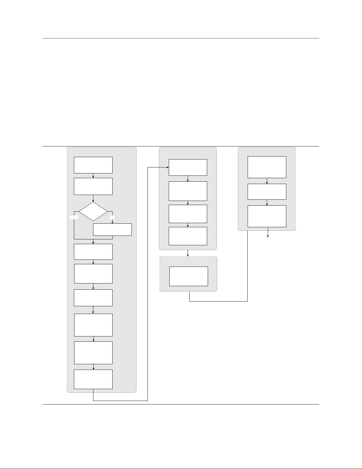
3.1
Configuration flowchart
Use the following flowchart as a general guide to the configuration and commissioning process.
Some options may not apply to your installation. Detailed information is provided in the remainder of this
manual.
Configure process measurement
Configure mass flow
measurement
Configure volume flow
meaurement
Volume flow type
Liquid
Configure flow direction
Configure density
measurement
Gas
Define gas properties
Configure device options and preferences
Configure display
parameters
Configure fault handling
parameters
Configure sensor
parameters
Configure device
parameters
Integrate device with control system
Configure digital
communications
Test and move to production
Test or tune transmitter
using sensor simulation
Back up transmitter
configuration
Enable write-protection on
transmitter configuration
Done
Configure temperature
measurement
Configure petroleum
measurement (API)
application (if available)
Configure concentration
measurement application (if
available)
Configure pressure
compensation (optional)
Configuration and Use Manual 13
Page 14

Introduction to configuration and commissioning Configuration and Use Manual
August 2022 20000326
3.2 Default values and ranges
See Default values and ranges to view the default values and ranges for the most commonly used parameters.
3.3
Display OFF-LINE MAINT → OFF-LINE CONFG
ProLink III Device Tools → Configuration → Transmitter Display → Display Security
Field Communicator Configure → Manual Setup → Display → Display Menu → Offline Menu
Fieldbus host LDO TB → EN_LDO_OFFLINE_MENU (OD Index 17)
By default, access to the off-line menu of the display is enabled. If it is disabled, you must enable it if you want
to use the display to configure the transmitter.
Restriction
You cannot use the display to enable access to the off-line menu. You must make a connection from another
tool.
Enable access to the off-line menu of the display
3.4 Disable write-protection on the transmitter
configuration
ProLink III Device Tools → Configuration → Write-Protection
Fieldbus Communicator Service Tools → Maintenance → Security and Simulation → Write Lock Setup
If the transmitter is write-protected, the configuration is locked and you must unlock it before you can change
any configuration parameters. By default, the transmitter is not write-protected.
Tip
Write-protecting the transmitter prevents accidental changes to configuration. It does not prevent normal
operational use. You can always disable write-protection, perform any required configuration changes, then
re-enable write-protection.
3.5 Place function, transducer, and resource blocks in
OOS mode
Prerequisites
Before you modify parameters on the fieldbus function blocks, you must place the function blocks in OOS
mode.
Procedure
Option Description
Display Not available
14 Micro Motion 2700 Transmitters with FOUNDATION Fieldbus
Page 15

Configuration and Use Manual Introduction to configuration and commissioning
20000326 August 2022
Option Description
ProLink III Device Tools → Configuration → Communications → Fieldbus
Field Communicator Overview → Mode
Fieldbus host (block name) → MODE_BLOCK (OD Index Number 005)
Postrequisites
Before you return the device to operation, you must place them back in service (Auto mode).
3.6
If you plan to use a fieldbus connection to configure the device, you can lock out fieldbus hosts. If you do this,
the fieldbus hosts will be able to read data from the device, but you will not be able to write data to the
device.
Restriction
This feature is available only if you are using the Field Communicator or AMS.
Procedure
Choose Service Tools → Maintenance → Security and Simulation → Write Lock Setup.
3.7
Display Not available
ProLink III Device Tools → Configuration Transfer → Restore Factory Configuration
Field communicator Service Tools → Maintenance → Reset/Restore → Master Reset
Fieldbus host Diagnostic TB → Restore Factory Config (OD Index 056)
Restoring the factory configuration returns the transmitter to the same configuration it had when it left the
factory. This may be useful if you experience problems during configuration.
Important
You cannot restore factory configurations with a 700 core.
Lockout FOUNDATION Fieldbus hosts
Restore the factory configuration
Tip
Restoring the factory configuration is not a common action. You may want to contact customer support to
see if there is a preferred method to resolve any issues.
3.8 Enable or disable fieldbus write lock
When locked, the fieldbus write lock prevents any configuration changes being written from the fieldbus
segment.
Procedure
Set the Write Lock parameter (OD index 34) of the Resource block to Locked (1) or Unlocked (0).
Configuration and Use Manual 15
Page 16

Introduction to configuration and commissioning Configuration and Use Manual
August 2022 20000326
16 Micro Motion 2700 Transmitters with FOUNDATION Fieldbus
Page 17

Configuration and Use Manual Configure process measurement
20000326 August 2022
4 Configure process measurement
4.1
The mass flow measurement parameters control how mass flow is measured and reported.
Configure mass flow measurement
4.1.1 Configure Mass Flow Measurement Unit
Display OFF-LINE MAINT → OFF-LINE CONFG → UNITS → MASS
ProLink III Device Tools → Configuration → Process Measurement → Flow
Field Communicator Configure → Manual Setup → Measurements → Flow → Mass Flow Unit
Fieldbus host Measurement TB → MFLOW_UNITS (OD Index 15)
Mass Flow Measurement Unit specifies the unit of measure that will be used for the mass flow rate. The unit
used for mass total and mass inventory is derived from this unit.
Procedure
Set Mass Flow Measurement Unit to the unit you want to use.
The default setting for Mass Flow Measurement Unit is g/sec (grams per second).
Tip
If the measurement unit you want to use is not available, you can define a special measurement unit.
Options for Mass Flow Measurement Unit
The transmitter provides a standard set of measurement units for Mass Flow Measurement Unit, plus one
user-defined special measurement unit. Different communications tools may use different labels for the
units.
Label
Unit description
Grams per second G/S g/sec g/s
Grams per minute G/MIN g/min g/min
Grams per hour G/H g/hr g/h
Kilograms per second KG/S kg/sec kg/s
Kilograms per minute KG/MIN kg/min kg/min
Kilograms per hour KG/H kg/hr kg/h
Kilograms per day KG/D kg/day kg/d
Metric tons per minute T/MIN mTon/min t/min
Metric tons per hour T/H mTon/hr t/h
Metric tons per day T/D mTon/day t/d
Pounds per second LB/S lbs/sec lb/s
Display ProLink III Field Communicator
Configuration and Use Manual 17
Page 18

Configure process measurement Configuration and Use Manual
August 2022 20000326
Label
Unit description
Pounds per minute LB/MIN lbs/min lb/min
Pounds per hour LB/H lbs/hr lb/h
Pounds per day LB/D lbs/day lb/d
Short tons (2000 pounds) per minute ST/MIN sTon/min STon/min
Short tons (2000 pounds) per hour ST/H sTon/hr STon/h
Short tons (2000 pounds) per day ST/D sTon/day STon/d
Long tons (2240 pounds) per hour LT/H lTon/hr LTon/h
Long tons (2240 pounds) per day LT/D lTon/day LTon/d
Special unit SPECL special Special
Display ProLink III Field Communicator
Define a special measurement unit for mass flow
Display Not available
ProLink III Device Tools → Configuration → Process Measurement → Flow → Special Units
Field Communicator Configure → Manual Setup → Measurements → Special Units → Mass Special Units
Fieldbus host
Measurement TB → MFLOW_SPECIAL_UNIT_BASE (OD Index 16)
Measurement TB → MFLOW_SPECIAL_UNIT_TIME (OD Index 17)
Measurement TB → MFLOW_SPECIAL_UNIT_CONV (OD Index 18)
Measurement TB → MFLOW_SPECIAL_UNIT_STR (OD Index 19)
A special measurement unit is a user-defined unit of measure that allows you to report process data, totalizer
data, and inventory data in a unit that is not available in the transmitter. A special measurement unit is
calculated from an existing measurement unit using a conversion factor.
Note
Although you cannot define a special measurement unit using the display, you can use the display to select an
existing special measurement unit, and to view process data using the special measurement unit.
The special unit label displays only on the local display. The AI block uses and displays the actual engineering
unit (i.e. lb/min).
Procedure
1. Specify Base Mass Unit.
Base Mass Unit is the existing mass unit that the special unit will be based on.
2. Specify Base Time Unit.
Base Time Unit is the existing time unit that the special unit will be based on.
3. Calculate Mass Flow Conversion Factor as follows:
a) x base units = y special units
b) Mass Flow Conversion Factor = x ÷ y
18 Micro Motion 2700 Transmitters with FOUNDATION Fieldbus
Page 19

Configuration and Use Manual Configure process measurement
20000326 August 2022
The original mass flow rate value is divided by this value.
4.
Enter Mass Flow Conversion Factor.
5. Set Mass Flow Label to the name you want to use for the mass flow unit.
6. Set Mass Total Label to the name you want to use for the mass total and mass inventory unit.
The special measurement unit is stored in the transmitter. You can configure the transmitter to use the
special measurement unit at any time.
Example: Defining a special measurement unit for mass flow
You want to measure mass flow in ounces per second (oz/sec).
1. Set Base Mass Unit to Pounds (lb).
2. Set Base Time Unit to Seconds (sec).
3. Calculate Mass Flow Conversion Factor:
a. 1 lb/sec = 16 oz/sec
b. Mass Flow Conversion Factor = 1 ÷ 16 = 0.0625
4. Set Mass Flow Conversion Factor to 0.0625.
5. Set Mass Flow Label to oz/sec.
6. Set Mass Total Label to oz.
4.1.2 Configure Flow Damping
Display Not available
ProLink III Device Tools → Configuration → Process Measurement → Flow
Field Communicator Configure → Manual Setup → Measurements → Flow → Flow Damping
Fieldbus host Measurement TB → FLOW_DAMPING → OD Index
Damping is used to smooth out small, rapid fluctuations in process measurement. Damping Value specifies
the time period (in seconds) over which the transmitter will spread changes in the process variable. At the end
of the interval, the internal value will reflect 63% of the change in the actual measured value.
Procedure
Set Flow Damping to the value you want to use.
• Default: 0.8 seconds
• Range: 0 seconds to 51.2 seconds
• Valid damping values: 0.0, 0.1, 0.2, 0.4, 0.8, 1.6, 3.2, 6.4, 12.8, 25.6, 51.2
Tip
• A high damping value makes the process variable appear smoother because the reported value changes
slowly.
• A low damping value makes the process variable appear more erratic because the reported value changes
more quickly.
Configuration and Use Manual 19
Page 20

Configure process measurement Configuration and Use Manual
August 2022 20000326
• The combination of a high damping value and rapid, large changes in flow rate can result in increased
measurement error.
• Whenever the damping value is non-zero, the reported measurement will lag the actual measurement
because the reported value is being averaged over time.
• In general, lower damping values are preferable because there is less chance of data loss, and less lag time
between the actual measurement and the reported value.
The value you enter is automatically rounded off to the nearest valid value. For example, if the damping is
currently set to 0.8 seconds, any value entered up to 1.2 seconds will be rounded down to 0.8 seconds, and
any value entered from 1.21 to 1.59 seconds will be rounded up to 1.6 seconds.
Effect of flow damping on volume measurement
Flow damping affects volume measurement for liquid volume data. Flow damping also affects volume
measurement for gas standard volume data. The transmitter calculates volume data from the damped mass
flow data.
4.1.3
Display Not available
ProLink III Device Tools → Configuration → Process Measurement → Flow
Field Communicator Configure → Manual Setup → Measurements → Flow → Mass Flow Cutoff
Fieldbus host Measurement TB → MASS_LOW_CUT (OD Index 38)
Mass Flow Cutoff specifies the lowest mass flow rate that will be reported as measured. All mass flow rates
below this cutoff will be reported as 0.
Procedure
Set Mass Flow Cutoff to the value you want to use.
The default value for Mass Flow Cutoff is 0.0 g/sec or a sensor-specific value set at the factory. The
recommended value is 0.5% of the nominal flow rate of the attached sensor. See the sensor specifications. Do
not leave Mass Flow Cutoff at 0.0 g/sec.
Configure Mass Flow Cutoff
Effect of Mass Flow Cutoff on volume measurement
Mass Flow Cutoff does not affect volume measurement. Volume data is calculated from the actual mass data
rather than the reported value.
Volume flow has a separate Volume Flow Cutoff that is not affected by the Mass Flow Cutoff value.
20 Micro Motion 2700 Transmitters with FOUNDATION Fieldbus
Page 21

Configuration and Use Manual Configure process measurement
20000326 August 2022
4.2 Configure volume flow measurement for liquid
applications
The volume flow measurement parameters control how liquid volume flow is measured and reported.
Restriction
You cannot implement both liquid volume flow and gas standard volume flow at the same time. Choose one
or the other.
4.2.1 Configure Volume Flow Type for liquid applications
Display Not available
ProLink III Device Tools → Configuration → Process Measurement → Flow
Field Communicator Configure → Manual Setup → Measurements → GSV → Volume Flow Type → Liquid
Fieldbus host Measurement TB → SNS_EnableGSV (OD Index 66)
Volume Flow Type controls whether liquid or gas standard volume flow measurement will be used.
Restriction
Gas standard volume measurement is incompatible with some applications. Set Volume Flow Type to Liquid
if you are using any of the following applications:
• Petroleum measurement
• Concentration measurement
Procedure
Set Volume Flow Type to Liquid.
4.2.2
Configure Volume Flow Measurement Unit for liquid
applications
Display OFF-LINE MAINT → OFF-LINE CONFG → UNITS → VOL
ProLink III Device Tools → Configuration → Process Measurement → Flow
Field Communicator Configure → Manual Setup → Measurements → Flow → Volume Flow Unit
Fieldbus host Measurement TB → VOLUME_FLOW_UNITS (OD Index 25)
Volume Flow Measurement Unit specifies the unit of measurement that will be displayed for the volume
flow rate. The unit used for the volume total and volume inventory is based on this unit.
Prerequisites
Before you configure Volume Flow Measurement Unit, be sure that Volume Flow Type is set to Liquid.
Procedure
Set Volume Flow Measurement Unit to the unit you want to use.
Configuration and Use Manual 21
Page 22

Configure process measurement Configuration and Use Manual
August 2022 20000326
To read US gallons, select that unit from this menu. G/MIN stands for grams per minute (USGPM), not gallons
per minute. The default setting for Volume Flow Measurement Unit is l/sec (liters per second).
Tip
If the measurement unit you want to use is not available, you can define a special measurement unit.
Options for Volume Flow Measurement Unit for liquid applications
The transmitter provides a standard set of measurement units for Volume Flow Measurement Unit, plus one
user-defined measurement unit. Different communications tools may use different labels for the units.
Label
Unit description
Cubic feet per second CUFT/S ft3/sec CFS
Cubic feet per minute CUF/MN ft3/min CFM
Cubic feet per hour CUFT/H ft3/hr CFH
Cubic feet per day CUFT/D ft3/day ft3/d
Cubic meters per second M3/S m3/sec m3/s
Cubic meters per minute M3/MIN m3/min m3/min
Cubic meters per hour M3/H m3/hr m3/h
Cubic meters per day M3/D m3/day m3/d
U.S. gallons per second USGPS US gal/sec gal/s
U.S. gallons per minute USGPM US gal/min GPM
U.S. gallons per hour USGPH US gal/hr gal/h
U.S. gallons per day USGPD US gal/day gal/d
Million U.S. gallons per day MILG/D mil US gal/day Mgal/d
Liters per second L/S l/sec L/s
Liters per minute L/MIN l/min L/min
Liters per hour L/H l/hr L/h
Display ProLink III Field Communicator
Million liters per day MILL/D mil l/day ML/d
Imperial gallons per second UKGPS Imp gal/sec Impgal/s
Imperial gallons per minute UKGPM Imp gal/min Impgal/min
Imperial gallons per hour UKGPH Imp gal/hr Impgal/h
Imperial gallons per day UKGPD Imp gal/day Impgal/d
Barrels per second
Barrels per minute BBL/MN barrels/min barrel(US Beer)/min
Barrels per hour BBL/H barrels/hr barrel(US Beer)/h
Barrels per day BBL/D barrels/day barrel(US Beer)/d
Beer barrels per second
22 Micro Motion 2700 Transmitters with FOUNDATION Fieldbus
(1)
(2)
BBL/S barrels/sec barrel(US Beer)/s
BBBL/S Beer barrels/sec bbbl/s
Page 23

Configuration and Use Manual Configure process measurement
20000326 August 2022
Label
Unit description
Beer barrels per minute BBBL/MN Beer barrels/min bbbl/min
Beer barrels per hour BBBL/H Beer barrels/hr bbbl/h
Beer barrels per day BBBL/D Beer barrels/day bbbl/d
(1) Unit based on oil barrels (42 U.S. gallons).
(2) Unit based on U.S. beer barrels (31 U.S. gallons).
Display ProLink III Field Communicator
Define a special measurement unit for volume flow
Display Not available
ProLink III Device Tools → Configuration → Process Measurement → Flow → Special Units
Field Communicator Configure → Manual Setup → Measurements → Special Units → Volume Special Units
Fieldbus host
A special measurement unit is a user-defined unit of measure that allows you to report process data, totalizer
data, and inventory data in a unit that is not available in the transmitter. A special measurement unit is
calculated from an existing measurement unit using a conversion factor.
Note
Although you cannot define a special measurement unit using the display, you can use the display to select an
existing special measurement unit, and to view process data using the special measurement unit.
The special unit label displays only on the local display. The AI block uses and displays the actual engineering
unit (i.e. L/min).
Measurement TB → VOL_SPECIAL_UNIT_BASE (OD Index 26)
Measurement TB → VOL _SPECIAL_UNIT_TIME (OD Index 27)
Measurement TB → VOL _SPECIAL_UNIT_CONV (OD Index 28)
Measurement TB → VOL _SPECIAL_UNIT_STR (OD Index 29)
Procedure
1. Specify Base Volume Unit.
Base Volume Unit is the existing volume unit that the special unit will be based on.
2. Specify Base Time Unit.
Base Time Unit is the existing time unit that the special unit will be based on.
3. Calculate Volume Flow Conversion Factor as follows:
a) x base units = y special units
b) Volume Flow Conversion Factor = x ÷ y
4. Enter Volume Flow Conversion Factor.
The original volume flow rate value is divided by this conversion factor.
5. Set Volume Flow Label to the name you want to use for the volume flow unit.
6. Set Volume Total Label to the name you want to use for the volume total and volume inventory unit.
Configuration and Use Manual 23
Page 24

Configure process measurement Configuration and Use Manual
August 2022 20000326
The special measurement unit is stored in the transmitter. You can configure the transmitter to use the
special measurement unit at any time.
Defining a special measurement unit for volume flow
You want to measure volume flow in pints per second (pints/sec).
1.
Set Base Volume Unit to Gallons (gal).
2. Set Base Time Unit to Seconds (sec).
3. Calculate the conversion factor:
a. 1 gal/sec = 8 pints/sec
b. Volume Flow Conversion Factor = 1 ÷ 8 = 0.1250
4. Set Volume Flow Conversion Factor to 0.1250.
5. Set Volume Flow Label to pints/sec.
6. Set Volume Total Label to pints.
4.2.3 Configure Volume Flow Cutoff
Display Not available
ProLink III Device Tools → Configuration → Process Measurement → Flow
Field Communicator Configure → Manual Setup → Measurements → Flow → Volume Flow Cutoff
Fieldbus host Measurement TB → VOLUME_FLOW_LOW_CUTOFF (OD Index 39)
Volume Flow Cutoff specifies the lowest volume flow rate that will be reported as measured. All volume flow
rates below this cutoff are reported as 0.
Procedure
Set Volume Flow Cutoff to the value you want to use.
The default value for Volume Flow Cutoff is 0.0 l/sec (liters per second). The lower limit is 0. Leaving the
volume flow cutoff at 0 is not recommended.
4.3
The gas standard volume (GSV) flow measurement parameters control how volume flow is measured and
reported in a gas application.
Restriction
You cannot implement both liquid volume flow and gas standard volume flow at the same time. Choose one
or the other.
Configure GSV flow measurement
4.3.1 Configure Volume Flow Type for gas applications
Display Not available
ProLink III Device Tools → Configuration → Process Measurement → Flow
24 Micro Motion 2700 Transmitters with FOUNDATION Fieldbus
Page 25

Configuration and Use Manual Configure process measurement
20000326 August 2022
Field Communicator Configure → Manual Setup → Measurements → GSV → Volume Flow Type → Standard Gas Volume
Fieldbus host
Measurement TB → GSV_Gas_Dens (OD Index 62)
Measurement TB → SNS_GSV_FlowUnits (OD Index 67)
Measurement TB → SNS_GSVflowFactor (OD Index 71)
Measurement TB → SNS_GSV_FlowCutoff (OD Index 74)
Volume Flow Type controls whether liquid or gas standard volume flow measurement is used.
Restriction
Gas standard volume measurement is incompatible with some applications. Set Volume Flow Type to Liquid
if you are using any of the following applications:
• Petroleum measurement
• Concentration measurement
Procedure
Set Volume Flow Type to Gas Standard Volume.
4.3.2
Display Not available
ProLink III Device Tools → Configuration → Process Measurement → Flow
Field Communicator Configure → Manual Setup → Measurements → GSV → Gas Ref Density
Fieldbus host Measurement TB → GSV_Gas_Dens (OD Index 62)
Configure Standard Density of Gas
The Standard Density of Gas value is the gas density at standard reference conditions. Use it to convert the
measured mass flow data to volume flow at reference conditions.
Prerequisites
Ensure that Density Measurement Unit is set to the measurement unit you want to use for Standard Density
of Gas.
Procedure
Set Standard Density of Gas to standard reference conditions.
4.3.3
Display OFF-LINE MAINT → OFF-LINE CONFG → UNITS → GSV
ProLink III Device Tools → Configuration → Process Measurement → Flow
Field Communicator Configure → Manual Setup → Measurements → GSV → GSV Flow Unit
Fieldbus host Measurement TB → SNS_GSV_FlowUnits (OD Index 67)
Configure Gas Standard Volume Flow Unit
Configuration and Use Manual 25
Page 26

Configure process measurement Configuration and Use Manual
August 2022 20000326
Gas Standard Volume Flow Unit specifies the unit of measure that will be displayed for the gas standard
volume flow. The measurement unit used for the gas volume total and the gas volume inventory is derived
from this unit.
Prerequisites
Before you configure Gas Standard Volume Flow Unit, be sure that Volume Flow Type is set to Gas Standard
Volume.
Procedure
Set Gas Standard Volume Flow Unit to the unit you want to use.
The default setting for Gas Standard Volume Flow Unit is SCFM (Standard Cubic Feet per Minute).
Tip
If the measurement unit you want to use is not available, you can define a special measurement unit.
Options for Gas Standard Volume Flow Unit
The transmitter provides a standard set of measurement units for Gas Standard Volume Flow Unit, plus one
user-defined special measurement unit. Different communications tools may use different labels for the
units.
Label
Unit description
Normal cubic meters per second NM3/S Nm3/sec Nm3/s
Normal cubic meters per minute NM3/MN Nm3/sec Nm3/min
Normal cubic meters per hour NM3/H Nm3/hr Nm3/h
Normal cubic meters per day NM3/D Nm3/day Nm3/d
Normal liters per second NLPS NLPS NL/s
Normal liters per minute NLPM NLPM NL/min
Normal liters per hour NLPH NLPH NL/h
Normal liters per day NLPD NLPD NL/d
Standard cubic feet per second SCFS SCFS SCFS
Standard cubic feet per minute SCFM SCFM SCFM
Standard cubic feet per hour SCFH SCFH SCFH
Standard cubic feet per day SCFD SCFD SCFD
Standard cubic meters per second SM3/S Sm3/sec Sm3/s
Standard cubic meters per minute SM3/MN Sm3/min Sm3/min
Standard cubic meters per hour SM3/H Sm3/hr Sm3/h
Display ProLink III Field Communicator
Standard cubic meters per day SM3/D Sm3/day Sm3/d
Standard liters per second SLPS SLPS SL/s
Standard liters per minute SLPM SLPM SL/min
Standard liters per hour SLPH SLPH SL/h
26 Micro Motion 2700 Transmitters with FOUNDATION Fieldbus
Page 27

Configuration and Use Manual Configure process measurement
20000326 August 2022
Label
Unit description
Standard liters per day SLPD SLPD SL/d
Special measurement unit SPECL special Special
Display ProLink III Field Communicator
Define a special measurement unit for gas standard volume flow
Display Not available
ProLink III Device Tools → Configuration → Process Measurement → Flow → Special Units
Field Communicator Configure → Manual Setup → Measurements → Special Units → Special GSV Units
Fieldbus host
A special measurement unit is a user-defined unit of measure that allows you to report process data, totalizer
data, and inventory data in a unit that is not available in the transmitter. A special measurement unit is
calculated from an existing measurement unit using a conversion factor.
Note
Although you cannot define a special measurement unit using the display, you can use the display to select an
existing special measurement unit, and to view process data using the special measurement unit.
The special unit label displays only on the local display. The AI block uses and displays the actual engineering
unit (i.e. SCFM).
Measurement TB → SNS_GSVflowBaseUnit (OD Index 69)
Measurement TB → SNS_GSVflowBaseTime (OD Index 70)
Measurement TB → SNS_GSVflowFactor (OD Index 71)
Measurement TB → SNS_GSVflowText (OD Index 72)
Procedure
1. Specify Base Gas Standard Volume Unit.
Base Gas Standard Volume Unit is the existing gas standard volume unit that the special unit will be
based on.
2. Specify Base Time Unit.
Base Time Unit is the existing time unit that the special unit will be based on.
3. Calculate Gas Standard Volume Flow Conversion Factor as follows:
a) x base units = y special units
b) Gas Standard Volume Flow Conversion Factor = x ÷ y
4. Enter the Gas Standard Volume Flow Conversion Factor.
The original gas standard volume flow value is divided by this conversion factor.
5. Set Gas Standard Volume Flow Label to the name you want to use for the gas standard volume flow
unit.
6. Set Gas Standard Volume Total Label to the name you want to use for the gas standard volume total
and gas standard volume inventory unit.
The special measurement unit is stored in the transmitter. You can configure the transmitter to use the
special measurement unit at any time.
Configuration and Use Manual 27
Page 28

Configure process measurement Configuration and Use Manual
August 2022 20000326
Example: Defining a special measurement unit for gas standard volume flow
You want to measure gas standard volume flow in thousands of standard cubic feet per minute.
1.
Set Base Gas Standard Volume Unit to SCF.
2. Set Base Time Unit to minutes (min).
3. Calculate the conversion factor:
a. 1 thousands of standard cubic feet per minute = 1000 cubic feet per minute
b. Gas Standard Volume Flow Conversion Factor = 1 ÷ 1000 = 0.001 standard
4. Set Gas Standard Volume Flow Conversion Factor to 0.001.
5. Set Gas Standard Volume Flow Label to MSCFM.
6. Set Gas Standard Volume Total Label to MSCF.
4.3.4 Configure Gas Standard Volume Flow Cutoff
Display Not available
ProLink III Device Tools → Configuration → Process Measurement → Flow
Field Communicator Configure → Manual Setup → Measurements → GSV → GSV Cutoff
Fieldbus host Measurement TB → SNS_GSV_FlowCutoff (OD Index 74)
Gas Standard Volume Flow Cutoff specifies the lowest gas standard volume flow rate that will reported as
measured. All gas standard volume flow rates below this cutoff will be reported as 0.
Procedure
Set Gas Standard Volume Flow Cutoff to the value you want to use.
The default value for Gas Standard Volume Flow Cutoff is 0.0. The lower limit is 0.0. There is no upper limit.
The recommended value is 0.5% of the nominal flow rate of the attached sensor. See the sensor
specifications.
4.4
Display Not available
ProLink III Device Tools → Configuration → Process Measurement → Flow
Field Communicator Configure → Manual Setup → Measurements → Flow → Flow Direction
Fieldbus host Measurement TB → FLOW_DIRECTION {OD Index 41)
Flow Direction controls how forward flow and reverse flow affect flow measurement and reporting.
Flow Direction is defined with respect to the flow arrow on the sensor:
• Forward flow (positive flow) moves in the direction of the flow arrow on the sensor.
• Reverse flow (negative flow) moves in the direction opposite to the flow arrow on the sensor.
Configure Flow Direction
28 Micro Motion 2700 Transmitters with FOUNDATION Fieldbus
Page 29

Configuration and Use Manual Configure process measurement
20000326 August 2022
Tip
Micro Motion sensors are bidirectional. Measurement accuracy is not affected by actual flow direction or the
setting of the Flow Direction parameter.
Procedure
Set Flow Direction to the value you want to use.
4.4.1
Forward Forward Appropriate when the Flow Direction arrow is in
Reverse Reverse Appropriate when the Flow Direction arrow is in
Absolute Value Absolute Value Flow Direction arrow is not relevant.
Bidirectional Bi directional Appropriate when both forward and reverse flow
Negate Forward Negate/Forward Only Appropriate when the Flow Direction arrow is in
Negate Bidirectional Negate/Bi-directional Appropriate when both forward and reverse flow
Options for Flow Direction
Flow Direction setting
Relationship to Flow Direction arrow on sensorProLink III Field Communicator
the same direction as the majority of flow.
the opposite direction from the majority of flow.
are expected, and forward flow will dominate, but
the amount of reverse flow will be significant.
the opposite direction from the majority of flow.
are expected, and reverse flow will dominate, but
the amount of forward flow will be significant.
Effect of flow direction on digital communications
Flow direction affects how flow values are reported via digital communications. The following table describes
the effect of the flow direction parameter and actual flow direction on flow values reported via digital
communications.
Table 4-1: Effect of the flow direction on flow values
Actual flow direction
Flow Direction setting
Forward Positive 0 Negative
Reverse Positive 0 Negative
Bidirectional Positive 0 Negative
Absolute Value Positive
Negate Forward Negative 0 Positive
Negate Bidirectional Negative 0 Positive
(1) Refer to the digital communications status bits for an indication of whether flow is positive or negative.
Configuration and Use Manual 29
Forward Zero flow Reverse
(1)
0 Positive
(1)
Page 30

Configure process measurement Configuration and Use Manual
August 2022 20000326
Effect of flow direction on flow totals
Flow direction affects how flow totals and inventories are calculated.
Actual flow direction
Flow Direction setting
Forward Totals increase Totals do not change Totals do not change
Bidirectional Totals increase Totals do not change Totals decrease
Negate Forward Totals do not change Totals do not change Totals increase
Negate Bidirectional Totals decrease Totals do not change Totals increase
Forward Zero flow Reverse
4.5 Configure density measurement
The density measurement parameters control how density is measured and reported.
4.5.1
Display OFF-LINE MAINT → OFF-LINE CONFG → UNITS → DENS
ProLink III Device Tools → Configuration → Process Measurement → Density
Field Communicator Configure → Manual Setup → Measurements → Density → Density Unit
Fieldbus host Measurement TB → DENSITY_UNITS (OD Index 23)
Density Measurement Unit controls the measurement units that will be used in density calculations and
reporting.
Procedure
Configure Density Measurement Unit
Set Density Measurement Unit to the option you want to use.
The default setting for Density Measurement Unit is g/cm3 (grams per cubic centimeter).
Options for Density Measurement Unit
The transmitter provides a standard set of measurement units for Density Measurement Unit. Different
communications tools may use different labels.
Label
Unit description
Specific gravity
Grams per cubic centimeter G/CM3 g/cm3 g/cm3
Grams per liter G/L g/l g/L
Grams per milliliter G/mL g/ml g/ml
Kilograms per liter KG/L kg/l kg/L
Kilograms per cubic meter KG/M3 kg/m3 kg/m3
Pounds per U.S. gallon LB/GAL lbs/Usgal lb/gal
30 Micro Motion 2700 Transmitters with FOUNDATION Fieldbus
(1)
Display ProLink III Field Communicator
SGU SGU SGU
Page 31

Configuration and Use Manual Configure process measurement
20000326 August 2022
Label
Unit description
Pounds per cubic foot LB/CUF lbs/ft3 lb/ft3
Pounds per cubic inch LB/CUI lbs/in3 lb/in3
Short ton per cubic yard ST/CUY sT/yd3 STon/yd3
Degrees API D API degAPI degAPI
(1) Non-standard calculation. This value represents line density divided by the density of water at 4 °C.
4.5.2
Display Not available
ProLink III Device Tools → Configuration → Process Measurement → Density
Field Communicator
Fieldbus host
Configure two-phase flow parameters
Configure → Manual Setup → Measurements → Density → Slug Low Limit
Configure → Manual Setup → Measurements → Density → Slug High Limit
Configure → Manual Setup → Measurements → Density → Slug Duration
Diag TB → SLUG_LOW_LIMIT (OD Index 15)
Diag TB → SLUG_HIGH_LIMIT (OD Index 16)
Diag TB → SLUG_TIME (OD Index 14)
Display ProLink III Field Communicator
The two-phase flow parameters control how the transmitter detects and reports two-phase flow (gas in a
liquid process or liquid in a gas process).
Note
Two-phase flow is also referred to as slug flow.
Procedure
Set Two-Phase Flow Low Limit to the lowest density value that is considered normal in your process.
1.
Values below this will cause the transmitter to post Alert A105 (Two-Phase Flow).
Tip
Gas entrainment can cause your process density to drop temporarily. To reduce the occurrence of twophase flow alerts that are not significant to your process, set Two-Phase Flow Low Limit slightly below
your expected lowest process density.
You must enter Two-Phase Flow Low Limit in g/cm³, even if you configured another unit for density
measurement.
2.
Set Two-Phase Flow High Limit to the highest density value that is considered normal in your process.
Micro Motion recommends leaving Two-Phase Flow High Limit at the default value.
Values above this will cause the transmitter to post Alert A105 (Two-Phase Flow).
You must enter Two-Phase Flow High Limit in g/cm³, even if you configured another unit for density
measurement.
3. Set Two-Phase Flow Timeout to the number of seconds that the transmitter will wait for a two-phase
flow condition to clear before posting the alert.
Configuration and Use Manual 31
Page 32

Configure process measurement Configuration and Use Manual
August 2022 20000326
The default value for Two-Phase Flow Timeout is 0.0 seconds, meaning that the alert will be posted
immediately. The range is 0.0 to 60.0 seconds.
The Two-Phase Flow alert is set immediately. The flow rate will hold the last measured value for the
Timeout time. Then the flow rate will report zero flow. If the density goes back in range, the error clears
immediately.
Detecting and reporting two-phase flow
Two-phase flow (gas in a liquid process or liquid in a gas process) can cause a variety of process control issues.
By configuring the two-phase flow parameters appropriately for your application, you can detect process
conditions that require correction.
Micro Motion recommends leaving Two-Phase Flow High Limit at the default value.
A two-phase flow condition occurs whenever the measured density goes below Two-Phase Flow Low Limit or
above Two-Phase Flow High Limit. If this occurs:
• A two-phase flow alert is posted to the active alert log.
• All outputs that are configured to represent flow rate hold their last pre-alert value for the number of
seconds configured in Two-Phase Flow Timeout.
If the two-phase flow condition clears before Two-Phase Flow Timeout expires:
• Outputs that represent flow rate revert to reporting actual flow.
• The two-phase flow alert is deactivated, but remains in the active alert log until it is acknowledged.
If the two-phase flow condition does not clear before Two-Phase Flow Timeout expires, the outputs that
represent flow rate report a flow rate of 0.
If Two-Phase Flow Timeout is set to 0.0 seconds, the outputs that represent flow rate will report a flow rate of
0 as soon as two-phase flow is detected.
4.5.3
Display Not available
ProLink III Device Tools → Configuration → Process Measurement → Density
Field Communicator Configure → Manual Setup → Measurements → Density → Density Damping
Fieldbus host Measurement TB → DENSITY_DAMPING (OD Index 34)
Density Damping controls the amount of damping that will be applied to the line density value.
Damping is used to smooth out small, rapid fluctuations in process measurement. Damping Value specifies
the time period (in seconds) over which the transmitter will spread changes in the process variable. At the end
of the interval, the internal value will reflect 63% of the change in the actual measured value.
Tip
Density damping affects all process variables that are calculated from line density.
Configure Density Damping
Procedure
Set Density Damping to the desired value.
32 Micro Motion 2700 Transmitters with FOUNDATION Fieldbus
Page 33

Configuration and Use Manual Configure process measurement
20000326 August 2022
• Default: 1.6 seconds
• Range: 0 to 51.2 seconds
• Valid damping values: 0.0, 0.1, 0.2, 0.4, 0.8, 1.6, 3.2, 6.4, 12.8, 25.6, 51.2
The default value is 1.6 seconds. The range depends on the core processor type and the setting of Update
Rate, as shown in the following table:
Tip
• A high damping value makes the process variable appear smoother because the reported value changes
slowly.
• A low damping value makes the process variable appear more erratic because the reported value changes
more quickly.
• The combination of a high damping value and rapid, large changes in flow rate can result in increased
measurement error.
• Whenever the damping value is non-zero, the reported measurement will lag the actual measurement
because the reported value is being averaged over time.
• In general, lower damping values are preferable because there is less chance of data loss, and less lag time
between the actual measurement and the reported value.
Effect of Density Damping on volume measurement
Density Damping affects liquid volume measurement. Liquid volume values are calculated from the damped
density value rather than the measured density value. Density Damping does not affect gas standard volume
measurement.
4.5.4
Display Not available
ProLink III Device Tools → Configuration → Process Measurement → Density
Field Communicator Configure → Manual Setup → Measurements → Density → Density Cutoff
Fieldbus host Measurement TB → DENSITY_LOW_CUTOFF (OD Index 38)
Density Cutoff specifies the lowest density value that will be reported as measured. All density values below
this cutoff will be reported as 0.
Procedure
Set Density Cutoff to the value you want to use.
For most applications, the default setting (0.2 g/cm³) is sufficient. The range is 0.0 g/cm³ to 0.5 g/cm³.
Configure Density Cutoff
Configuration and Use Manual 33
Page 34

Configure process measurement Configuration and Use Manual
August 2022 20000326
Effect of Density Cutoff on volume measurement
Density Cutoff affects liquid volume measurement. If the density value goes below Density Cutoff, the
volume flow rate is reported as 0.
4.6
The temperature measurement parameters control how temperature data from the sensor is reported.
Configure temperature measurement
4.6.1 Configure Temperature Measurement Unit
Display OFF-LINE MAINT → OFF-LINE CONFG → UNITS → TEMP
ProLink III Device Tools → Configuration → Process Measurement → Temperature
Field Communicator Configure → Manual Setup → Measurements → Temperature → Temperature Unit
Fieldbus host Measurement TB → TEMPERATURE_UNITS (OD Index 21)
Temperature Measurement Unit specifies the unit that will be used for temperature measurement.
Procedure
Set Temperature Measurement Unit to the option you want to use.
The default setting is Degrees Celsius.
Options for Temperature Measurement Unit
The transmitter provides a standard set of units for Temperature Measurement Unit. Different
communications tools may use different labels for the units.
Label
Unit description
Degrees Celsius °C °C degC
Degrees Fahrenheit °F °F degF
Degrees Rankine °R °R degR
Kelvin °K °K K
Display ProLink III Field Communicator
4.6.2 Configure Temperature Damping
Display Not available
ProLink III Device Tools → Configuration → Temperature
Field Communicator Configure → Manual Setup → Measurements → Temperature → Temp Damping
Fieldbus host Measurement TB → TEMPERATURE_DAMPING (OD Index 33)
34 Micro Motion 2700 Transmitters with FOUNDATION Fieldbus
Page 35

Configuration and Use Manual Configure process measurement
20000326 August 2022
Temperature Damping controls the amount of damping that will be applied to the line temperature value,
when the on-board temperature data is used (RTD).
Damping is used to smooth out small, rapid fluctuations in process measurement. Damping Value specifies
the time period (in seconds) over which the transmitter will spread changes in the process variable. At the end
of the interval, the internal value will reflect 63% of the change in the actual measured value.
Tip
Temperature Damping affects all process variables, compensations, and corrections that use temperature
data from the sensor.
Procedure
Enter the value you want to use for Temperature Damping.
The default value is 4.8 seconds. For most applications, the default temperature damping setting is sufficient.
The range is 0.0 to 38.4 seconds.
Tip
• A high damping value makes the process variable appear smoother because the reported value changes
slowly.
• A low damping value makes the process variable appear more erratic because the reported value changes
more quickly.
• Whenever the damping value is non-zero, the reported measurement will lag the actual measurement
because the reported value is being averaged over time.
• In general, lower damping values are preferable because there is less chance of data loss, and less lag time
between the actual measurement and the reported value.
The value you enter is automatically rounded off to the nearest valid value. Valid values for Temperature
Damping are 0, 0.6, 1.2, 2.4, 4.8, 9.6, 19.2, and 38.4.
4.6.3
Temperature Damping affects all processes and algorithms that use temperature data from the internal
sensor RTD.
Temperature compensation
Temperature compensation adjusts process measurement to compensate for the effect of temperature on
the sensor tubes.
Petroleum measurement
Temperature Damping affects petroleum measurement process variables only if the transmitter is
configured to use temperature data from the sensor. If an external temperature value is used for petroleum
measurement, Temperature Damping does not affect petroleum measurement process variables.
Effect of Temperature Damping on process measurement
Concentration measurement
Temperature Damping affects concentration measurement process variables only if the transmitter is
configured to use temperature data from the sensor. If an external temperature value is used for
concentration measurement, Temperature Damping does not affect concentration measurement process
variables.
Configuration and Use Manual 35
Page 36

Configure process measurement Configuration and Use Manual
August 2022 20000326
4.7 Configure the petroleum measurement application
The petroleum measurement application corrects line density to reference temperature according to
American Petroleum Institute (API) standards. The resulting process variable is referred density.
4.7.1
The petroleum measurement parameters specify the API table, measurement units, and reference values to
be used in referred density calculations.
Prerequisites
You will need API documentation for the API table that you select.
Depending on your API table, you may need to know the thermal expansion coefficient (TEC) for your process
fluid.
You must know the reference temperature that you want to use.
Procedure
Configure petroleum measurement using ProLink III
1. Choose Device Tools → Configuration → Process Measurement → Petroleum Measurement.
2. Specify the API table to use to calculate referred density.
Each API table is associated with a specific set of equations.
a) Set Process Fluid to the API table group that your process fluid belongs to.
API table group Process fluids
A tables Generalized crude and JP4
B tables Generalized products: Gasoline, jet fuel, aviation fuel, kerosene, heating oils,
fuel oils, diesel, gas oil
C tables Liquids with a constant base density or known thermal expansion coefficient
(TEC). You will be required to enter the TEC for your process fluid.
D tables Lubricating oils
b) Set Referred Density Measurement Unit to the measurement units that you want to use for
referred density.
Click Apply.
c)
These parameters uniquely identify the API table to be used to calculate referred density. The selected
API table is displayed, and the meter automatically changes the density unit, temperature unit,
pressure unit, and reference pressure to match the API table.
Your choice also determines the API table that will be used to calculate the correction factor for volume
(CTL).
Restriction
Not all combinations are supported by the petroleum measurement application. See the list of API
tables in this manual.
3. Refer to the API documentation and confirm your table selection.
36 Micro Motion 2700 Transmitters with FOUNDATION Fieldbus
Page 37

Configuration and Use Manual Configure process measurement
20000326 August 2022
a) Verify that your process fluid falls within range for line density, line temperature, and line
pressure.
b)
Verify that the referred density range of the selected table is adequate for your application.
4. If you chose a C table, enter Thermal Expansion Coefficient (TEC) for your process fluid.
5. Set Reference Temperature to the temperature to which density will be corrected in referred density
calculations. If you choose Other, select the temperature measurement unit and enter the reference
temperature.
4.7.2 Configure petroleum measurement using the Field
Communicator
Procedure
1. Choose Online → Configure → Manual Setup → Measurements → Petroleum Measurement.
2. Specify the API table to use.
a) Open the Petroleum Measurement Source menu and select the API table number.
Depending on your choice, you may be prompted to enter a reference temperature or a thermal
expansion coefficient.
b) Enter the API table letter.
These two parameters uniquely specify the API table.
3. Determine how the transmitter will obtain temperature data for the petroleum measurement
calculations, and perform the required setup.
Option Setup
Temperature data from
the sensor
A user-configured static
temperature value
A value written by
digital communications
a. Choose Online → Configure → Manual Setup → Measurements →
External Inputs
b.
Set External Temperature to Disabled
a. Choose Online → Configure → Manual Setup → Measurements →
External Inputs
Set External Temperature to Enabled
b.
c. Set Correction Temperature to the value to be used.
a. Choose Online → Configure → Manual Setup → Measurements →
External Inputs
Set External Temperature to Enabled
b.
c. Hook up the AO Function block of the transmitter to the input of the
external device to write the external temperature to the transmitter.
Configuration and Use Manual 37
Page 38

Configure process measurement Configuration and Use Manual
August 2022 20000326
4.7.3 API tables supported by the petroleum measurement
application
The API tables listed here are supported by the petroleum measurement application.
Table
name Process fluid CTL source data Reference temperature Density unit
5A Generalized crude and
JP4
5B Generalized products Observed density and
5D Lubricating oils Observed density and
6C Liquids with a constant
density base or known
thermal expansion
coefficient
23A Generalized crude and
JP4
23B Generalized products Observed density and
23D Lubricating oils Observed density and
24C Liquids with a constant
density base or known
thermal expansion
coefficient
Observed density and
observed temperature
observed temperature
observed temperature
User-supplied reference
density (or thermal
expansion coefficient)
and observed
temperature
Observed density and
observed temperature
observed temperature
observed temperature
User-supplied reference
density (or thermal
expansion coefficient)
and observed
temperature
60 °F (configurable) Degrees API
Range: 0 to 100
60 °F (configurable) Degrees API
Range: 0 to 85
60 °F (configurable) Degrees API
Range: −10 to +45
60 °F (configurable) Degrees API
60 °F (configurable) Relative density
Range: 0.6110 to 1.0760
60 °F (configurable) Relative density
Range: 0.6535 to 1.0760
60 °F (configurable) Relative density
Range: 0.8520 to 1.1640
60 °F (configurable) Relative density
53A Generalized crude and
JP4
53B Generalized products Observed density and
53D Lubricating oils Observed density and
54C Liquids with a constant
density base or known
thermal expansion
coefficient
38 Micro Motion 2700 Transmitters with FOUNDATION Fieldbus
Observed density and
observed temperature
observed temperature
observed temperature
User-supplied reference
density (or thermal
expansion coefficient)
and observed
temperature
15 °C (configurable) Base density
Range: 610 to
1075 kg/m
15 °C (configurable) Base density
Range: 653 to
1075 kg/m
15 °C (configurable) Base density
Range: 825 to
1164 kg/m
15 °C (configurable) Base density in kg/m
3
3
3
3
Page 39

Configuration and Use Manual Configure process measurement
20000326 August 2022
Restriction
These tables are not appropriate for the following process fluids: propane and propane mixes, butane and
butane mixes, butadiene and butadiene mixes, isopentane, LNG, LPG, NGL, ethylene, propylene, cyclohexane,
aeromatics, asphalts, and road tars.
4.8 Set up concentration measurement
This section guides you through loading and setting up a concentration matrix used for measurement. It does
not cover building a concentration matrix.
The concentration measurement application calculates concentration data from process temperature and
density. Micro Motion provides a set of concentration matrices that provide the reference data for several
standard industry applications and process fluids. If desired, you can build a custom matrix for your process
fluid, or purchase a custom matrix from Micro Motion.
Note
Concentration matrices can be made available on your transmitter either by loading an existing matrix from a
file or by building a new matrix. Up to 6 matrices can be available on your transmitter, but only 1 can be used
for measurement at any given time. For detailed information on building a matrix, see the Micro Motion
Enhanced Density Application Manual.
Prerequisites
Before you can configure concentration measurement:
• The concentration measurement application must be purchased on your transmitter.
• The concentration matrix you want to use must be available on your transmitter, or it must be available as
a file on your computer.
• You must know the derived variable that your matrix is designed for.
• You must know the density unit used by your matrix.
• You must know the temperature unit used by your matrix.
• The concentration measurement application must be unlocked.
4.8.1
Procedure
Configure concentration measurement using ProLink III
1. Choose Device Tools → Configuration → Process Measurement → Density and set Density Unit to
the density unit used by your matrix.
2. Choose Device Tools → Configuration → Process Measurement → Temperature and set
Temperature Unit to the temperature unit used by your matrix.
3. Choose Device Tools → Configuration → Process Measurement → Concentration Measurement.
4. Set Derived Variable to the derived variable that your matrix is designed for, and click Apply.
Important
• All concentration matrices on your transmitter must use the same derived variable. If you are using
one of the standard matrices from Micro Motion, set Derived Variable to Mass Concentration
(Density). If you are using a custom matrix, see the reference information for your matrix.
Configuration and Use Manual 39
Page 40

Configure process measurement Configuration and Use Manual
August 2022 20000326
• If you change the setting of Derived Variable, all existing concentration matrices will be deleted
from transmitter memory. Set Derived Variable before loading concentration matrices.
5. Load one or more matrices.
Set Matrix Being Configured to the location to which the matrix will be loaded.
a)
b) Click Load Matrix from a File, navigate to the matrix file on your computer, and load it.
c) Repeat until all required matrices are loaded.
6. Configure or review matrix data.
a) If necessary, set Matrix Being Configured to the matrix you want to configure or review, and
click Change Matrix.
b) Set Concentration Unit to the label that will be used for the concentration unit.
c) If you set Concentration Unit to Special, enter the custom label.
d) If desired, change the matrix name.
e) Review the data points for this matrix.
f) Do not change Reference Temperature or Curve Fit Maximum Order.
g) If you changed any matrix data, click Apply.
7. Set up extrapolation alarms.
Each concentration matrix is built for a specific density range and a specific temperature range. If
process density or process temperature goes outside the range, the transmitter will extrapolate
concentration values. However, extrapolation may affect accuracy. Extrapolation alarms are used to
notify the operator that extrapolation is occurring.
a) If necessary, set Matrix Being Configured to the matrix you want to view, and select Change
Matrix.
b) Set Extrapolation Alarm Limit to the point, in percent, at which an extrapolation alarm will be
posted.
c) Enable or disable the high and low limit alarms for temperature and density, as desired, and
select Apply.
Example
If Extrapolation Alarm Limit is set to 5%, High Extrapolation Limit (Temperature) is enabled, and the
matrix is built for a temperature range of 40 °F (4.4 °C) to 80 °F (26.7 °C), an extrapolation alarm will be
posted if process temperature goes above 82 °F (27.8 °C).
Concentration process variables are now available on the transmitter. You can view and report them in the
same way that you view and report other process variables.
40 Micro Motion 2700 Transmitters with FOUNDATION Fieldbus
Page 41

Configuration and Use Manual Configure process measurement
20000326 August 2022
4.8.2 Configure concentration measurement using the Field Communicator
Procedure
1.
Choose Online → Configure → Manual Setup → Measurements → External Outputs.
2. Set Pressure Compensation to Enabled.
3. Enter Flow Cal Pressurefor your sensor.
The calibration pressure is the pressure at which your sensor was calibrated, and defines the pressure at
which there is no pressure effect. If the data is unavailable, enter 20 PSI.
4. Enter Dens Press Factor for your sensor.
The density factor is the change in fluid density, in g/cm3/PSI. When entering the value, reverse the
sign.
Example
If the density factor is 0.000006 g/com3/PSI, enter -0.000006 g/cm3/PSI.
5. Determine how the transmitter will obtain pressure data, and perform the required setup.
Option Setup
A user-configured static pressure value a. Set Pressure Unit to the desired unit.
b. Set Compensation Pressure to the desired
value.
A value written by digital communications a. Choose Pressure Unit to the desired unit.
b. Perform the necessary host programming and
communications setup to write pressure data to
the transmitter at appropriate intervals .
Postrequisites
If you are using an external pressure value, verify the setup by choosing Service Tools → Variables → External
Variables and checking the value displayed for External Pressure.
4.8.3
Standard matrices for the concentration measurement
application
The standard concentration matrices available from Micro Motion are applicable for a variety of process fluids.
These matrices are included in the ProLink III installation folder.
Tip
If the standard matrices are not appropriate for your application, you can build a custom matrix or purchase a
custom matrix from Micro Motion.
Configuration and Use Manual 41
Page 42

Configure process measurement Configuration and Use Manual
August 2022 20000326
Matrix name Description Density unit
Deg Balling Matrix represents percent extract, by
g/cm
3
mass, in solution, based on °Balling.
For example, if a wort is 10 °Balling and
the extract in solution is 100% sucrose,
the extract is 10% of the total mass.
Deg Brix Matrix represents a hydrometer scale
g/cm
3
for sucrose solutions that indicates the
percent by mass of sucrose in solution
at a given temperature. For example,
40 kg of sucrose mixed with 60 kg of
water results in a 40 °Brix solution.
Deg Plato Matrix represents percent extract, by
g/cm
3
mass, in solution, based on °Plato. For
example, if a wort is 10 °Plato and the
extract in solution is 100% sucrose, the
extract is 10% of the total mass.
HFCS 42 Matrix represents a hydrometer scale
g/cm
3
for HFCS 42 (high-fructose corn syrup)
solutions that indicates the percent by
mass of HFCS in solution.
HFCS 55 Matrix represents a hydrometer scale
g/cm
3
for HFCS 55 (high-fructose corn syrup)
solutions that indicates the percent by
mass of HFCS in solution.
HFCS 90 Matrix represents a hydrometer scale
g/cm
3
for HFCS 90 (high-fructose corn syrup)
solutions that indicates the percent by
mass of HFCS in solution.
Temperature
unit
Derived variable
°F Mass
Concentration
(Density)
°C Mass
Concentration
(Density)
°F Mass
Concentration
(Density)
°C Mass
Concentration
(Density)
°C Mass
Concentration
(Density)
°C Mass
Concentration
(Density)
4.8.4 Derived variables and calculated process variables
The concentration measurement application calculates a different set of process variables from each derived
variable. The process variables are then available for viewing or reporting.
Calculated process variables
Derived
variable
Density
at Reference
Description
Mass/unit volume,
corrected to a given
reference temperature
42 Micro Motion 2700 Transmitters with FOUNDATION Fieldbus
Density
at
reference
temp
✓ ✓
Standard
volume
flow rate
Specific
gravity
Concentration
Net mass
flow rate
Net
volume
flow rate
Page 43

Configuration and Use Manual Configure process measurement
20000326 August 2022
Calculated process variables
Derived
variable
Specific Gravity The ratio of the
Mass
Concentration
(Density)
Mass
Concentration
(Specific
Gravity)
Description
density of a process
fluid at a given
temperature to the
density of water at a
given temperature
Note
The two given
temperature
conditions do not
need to be the same.
The percent mass of
solute or of material in
suspension in the total
solution, derived from
reference density
The percent mass of
solute or of material in
suspension in the total
solution, derived from
specific gravity
Density
at
reference
temp
✓ ✓ ✓
✓ ✓ ✓ ✓
✓ ✓ ✓ ✓ ✓
Standard
volume
flow rate
Specific
gravity
Concentration
Net mass
flow rate
Net
volume
flow rate
Volume
Concentration
(Density)
Volume
Concentration
(Specific
Gravity)
Concentration
(Density)
Concentration
(Specific
Gravity)
The percent volume of
solute or of material in
suspension in the total
solution, derived from
reference density
The percent volume of
solute or of material in
suspension in the total
solution, derived from
specific gravity
The mass, volume,
weight, or number of
moles of solute or of
material in suspension
in proportion to the
total solution, derived
from reference density
The mass, volume,
weight, or number of
moles of solute or of
material in suspension
in proportion to the
total solution, derived
from specific gravity
✓ ✓ ✓ ✓
✓ ✓ ✓ ✓ ✓
✓ ✓ ✓
✓ ✓ ✓ ✓
Configuration and Use Manual 43
Page 44

Configure process measurement Configuration and Use Manual
August 2022 20000326
4.9 Set up concentration measurement using a basic FF host
This section guides you through most of the tasks related to setting up and implementing the concentration
measurement application.
Restriction
This section does not cover building a concentration matrix. See Micro Motion Enhanced Density Application
Manual for detailed information on building a matrix.
4.9.1 Set reference temperature values for specific gravity using a basic FF host
When Derived Variable is set to any option based on specific gravity, you must set the reference temperature
for water, then verify the density of water at the configured reference temperature. These values affect
specific gravity measurement.
To check the setting of Derived Variable, read the value of the Derived Variable parameter in the
Concentration Measuremnt TB.
Table 4-2: Fieldbus codes for derived variable options (Derived Variable parameter)
Fieldbus code Derived variable
1 Density at reference temperature
2 Specific gravity
3 Mass concentration (density)
4 Mass concentration (specific gravity)
5 Volume concentration (density)
6 Volume concentration (specific gravity)
7 Concentration (density)
8 Concentration (specific gravity)
Important
Do not change the setting of Derived Variable. If you change the setting of Derived Variable, all existing
concentration matrices will be deleted from transmitter memory.
Procedure
Write the desired values into the appropriate parameters in the Concentration Measuremnt TB for Reference
Temperature, Water Reference Temperature, and Water Reference Density.
The transmitter automatically calculates the density of water at the specified temperature. The new value will
be displayed the next time that transmitter memory is read. You can enter a different value if you want to.
44 Micro Motion 2700 Transmitters with FOUNDATION Fieldbus
Page 45

Configuration and Use Manual Configure process measurement
20000326 August 2022
4.9.2 Modify matrix names and labels using a basic FF host
For convenience, you can change the name of a concentration matrix and the label used for its measurement
unit. This does not affect measurement.
Procedure
1.
Choose the matrix you want to modify by writing to the Matrix Being Configured parameter in the
Concentration Measuremnt TB. Each saved matrix has a unique value of 0 through 5.
2. Write the desired values into the Matrix Name and Concentration Unit parameters in the
Concentration Measuremnt TB.
Table 4-3: Concentration unit codes
Fieldbus code Unit
1110 degTwad
1426 degBrix
1111 degBaum hv
1112 degBaum It
1343 % sol/wt
1344 % sol/vol
1427 degBall
1428 proof/vol
1429 proof/mass
1346 % plato
253 special
3. Write a value into the Special Concentration Unit Label parameter if Concentration Unit is set to code
253 (special).
4.9.3
Modify extrapolation alerts for concentration measurement
using a basic FF host
You can enable and disable extrapolation alerts, and set extrapolation alert limits. These parameters control
the behavior of the concentration measurement application but do not affect measurement directly.
Each concentration matrix is built for a specific density range and a specific temperature range. If line density
or line temperature goes outside the range, the transmitter will extrapolate concentration values. However,
extrapolation may affect accuracy. Extrapolation alerts are used to notify the operator that extrapolation is
occurring.
Each concentration matrix has its own extrapolation alert limits.
Procedure
1. Choose the matrix you want to configure using the Active Matrix parameter in the Concentration
Measuremnt TB. Each saved matrix has a unique value of 0 through 5.
2. Write the desired values into the appropriate parameters in the Concentration Measuremnt TB.
Configuration and Use Manual 45
Page 46

Configure process measurement Configuration and Use Manual
August 2022 20000326
Parameter name Description
Extrapolation Limit Extrapolation Alert Limit The point, in percent, at which an
extrapolation alert will be posted.
Density Low Enable low density extrapolation alarm (write 1 to enable; 0 to
disable).
Density High Enable high density extrapolation alarm (write 1 to enable; 0 to
disable).
Temperature Low Enable low temperature extrapolation alarm (write 1 to enable; 0
to disable).
Temperature High Enable high temperature extrapolation alarm (write 1 to enable; 0
to disable).
Extrapolation alert in action
If the following conditions exist, the high temperature extrapolation alert will be posted when the line
temperature exceeds 82 °F (27.8 °C):
• The Extrapolation Alert Limit is set to 5%
• The high temperature alarm is enabled
• The active matrix is built for a temperature range of 40 °F (4.4 °C) to 80 °F (26.7 °C)
4.9.4
You must select the concentration matrix to be used for measurement. Although the transmitter can store up
to six concentration matrices, only one matrix can be used for measurement at any one time.
Procedure
Choose the matrix you want to use by writing to the Active Matrix parameter in the Concentration
Measuremnt TB. Each saved matrix has a unique value of 0 through 5.
Select the active concentration matrix using a basic FF host
4.10 Configure pressure compensation
Pressure compensation adjusts process measurement to compensate for the pressure effect on the sensor.
The pressure effect is the change in the sensor’s sensitivity to flow and density caused by the difference
between the calibration pressure and the process pressure.
Tip
Not all sensors or applications require pressure compensation. The pressure effect for a specific sensor model
can be found in the product data sheet located at Emerson.com. If you are uncertain about implementing
pressure compensation, contact customer service.
Prerequisites
You will need the flow factor, density factor, and calibration pressure values for your sensor.
• For the flow factor and density factor, see the product data sheet for your sensor.
• For the calibration pressure, see the calibration sheet for your sensor. If the data is unavailable, use 20 PSI.
46 Micro Motion 2700 Transmitters with FOUNDATION Fieldbus
Page 47

Configuration and Use Manual Configure process measurement
20000326 August 2022
4.10.1 Configure pressure compensation using ProLink III
Procedure
1.
Choose Device Tools → Configuration → Process Measurement → Pressure Compensation.
2. Set Pressure Unit to the appropriate unit.
If you will use an external pressure value, set Pressure Unit to match the pressure unit used by the
external pressure device.
3. Enter Flow Calibration Pressure for your sensor.
The calibration pressure is the pressure at which your sensor was calibrated, and defines the pressure at
which there is no pressure effect. If the data is unavailable, enter 20 PSI.
4. Enter Flow Factor for your sensor.
The flow factor is the percent change in the flow rate per PSI. When entering the value, reverse the
sign.
Example
If the flow factor is 0.000004 % per PSI, enter −0.000004 % per PSI.
5. Enter Density Factor for your sensor.
The density factor is the change in fluid density, in g/cm3/PSI. When entering the value, reverse the
sign.
Example
If the density factor is −0.000006 g/cm3/PSI, enter +0.000006 g/cm3/PSI.
Postrequisites
If you are using an external pressure value, verify the setup by checking the External Pressure value displayed
in the Inputs area of the main window.
4.10.2 Configure pressure compensation using the Field Communicator
Procedure
1. Choose Online → Configure → Manual Setup → Measurements → External Inputs.
2. Set Pressure Compensation to Enabled.
3. Enter Flow Cal Pressure for your sensor.
The calibration pressure is the pressure at which your sensor was calibrated, and defines the pressure at
which there is no pressure effect. If the data is unavailable, enter 20 PSI.
4. Enter Flow Press Factor for your sensor.
The flow factor is the percent change in the flow rate per PSI. When entering the value, reverse the
sign.
Configuration and Use Manual 47
Page 48

Configure process measurement Configuration and Use Manual
August 2022 20000326
Example
If the flow factor is −0.0002 % per PSI, enter +0.0002 % per PSI.
5.
Enter Dens Press Factor for your sensor.
The density factor is the change in fluid density, in g/cm3/PSI. When entering the value, reverse the
sign.
Example
If the density factor is −0.000006 g/cm3/PSI, enter +0.000006 g/cm3/PSI.
6. Determine how the transmitter will obtain pressure data, and perform the required setup.
Option Setup
A user-configured static
pressure value
A value written by
digital communications
a. Set Pressure Unit to the desired unit.
Set Compensation Pressure to the desired value.
b.
a. Set Pressure Unit to the desired unit.
Perform the necessary host programming and communications setup
b.
to write pressure data to the transmitter at appropriate intervals.
Postrequisites
If you are using an external pressure value, verify the setup by choosing Service Tools → Variables → External
Variables and checking the value displayed for External Pressure.
4.10.3
Options for Pressure Measurement Unit
The transmitter provides a standard set of measurement units for Pressure Measurement Unit. Different
communications tools may use different labels for the units. In most applications, Pressure Measurement
Unit should be set to match the pressure measurement unit used by the remote device.
Label
Unit description
Feet water @ 68 °F FTH2O Ft Water @ 68 °F ftH2O (68°F)
Display ProLink III Field Communicator
Inches water @ 4 °C INW4C In Water @ 4 °C inH2O (4°C)
Inches water @ 60 °F INW60 In Water @ 60 °F inH2O@60°F
Inches water @ 68 °F INH2O In Water @ 68 °F inH2O (68°F)
Millimeters water @ 4 °C mmW4C mm Water @ 4 °C mmH2O (4°C)
Millimeters water @ 68 °F mmH2O mm Water @ 68°F mmH2O (68°F)
Millimeters mercury @ 0 °C mmHG mm Mercury @ 0 °C mmHg (0°C)
Inches mercury @ 0 °C INHG In Mercury @ 0°C inHg (0°C)
Pounds per square inch PSI PSI psi
48 Micro Motion 2700 Transmitters with FOUNDATION Fieldbus
Page 49

Configuration and Use Manual Configure process measurement
20000326 August 2022
Label
Unit description
Bar BAR bar bar
Millibar mBAR millibar mbar
Grams per square centimeter G/SCM g/cm2 g/cm2
Kilograms per square centimeter KG/SCM kg/cm2 kg/cm2
Pascals PA pascals Pa
Kilopascals KPA Kilopascals kPa
Megapascals MPA Megapascals MPa
Torr @ 0 °C TORR Torr @ 0°C torr
Atmospheres ATM atms atm
Display ProLink III Field Communicator
Configuration and Use Manual 49
Page 50

Configure process measurement Configuration and Use Manual
August 2022 20000326
50 Micro Motion 2700 Transmitters with FOUNDATION Fieldbus
Page 51

Configuration and Use Manual Configure device options and preferences
20000326 August 2022
5 Configure device options and preferences
5.1
You can control the process variables shown on the display and a variety of display behaviors.
Configure the transmitter display
5.1.1 Configure the language used for the display
Display OFF-LINE MAINT → OFF-LINE CONFG → DISPLAY → LANG
ProLink III Device Tools → Configuration → Transmitter Display → General
Field Communicator Configure → Manual Setup → Display → Language
Fieldbus host LDO TB → UI_Language (OD Index 24)
Display Language controls the language used for process data and menus on the display.
Procedure
Select the language you want to use.
The languages available depend on your transmitter model and version.
5.1.2
Configure the process variables and diagnostic variables
shown on the display
Display Not available
ProLink III Device Tools → Configuration → Transmitter Display → Display Variables
Field Communicator Configure → Manual Setup → Display → Display Variables
Fieldbus host LDO TB → LDO_VAR_1_CODE (OD Index 25) to
LDO TB → LDO_VAR_15_CODE (OD Index 39)
You can control the process variables and diagnostic variables shown on the display, and the order in which
they appear. The display can scroll through up to 15 variables in any order you choose. In addition, you can
repeat variables or leave slots unassigned.
Restriction
Display Variable 1 must be set to a process variable.
Note
If you configure a display variable as a volume process variable and then change Volume Flow Type, the
display variable is automatically changed to the equivalent process variable. For example, Volume Flow Rate
would be changed to Gas Standard Volume Flow Rate.
Procedure
For each display variable you want to change, assign the process variable you want to use.
Configuration and Use Manual 51
Page 52

Configure device options and preferences Configuration and Use Manual
August 2022 20000326
Default display variable configuration
Display variable Process variable assignment
Display Variable 1
Display Variable 2
Display Variable 3
Display Variable 4
Display Variable 5
Display Variable 6
Display Variable 7
Display Variable 8
Display Variable 9
Display Variable 10
Display Variable 11
Display Variable 12
Display Variable 13
Display Variable 14
Display Variable 15
Mass flow
Mass total
Volume flow
Volume total
Density
Temperature
Drive gain
None
None
None
None
None
None
None
None
5.1.3 Configure the number of decimal places (precision) shown on the display
Display Not available
ProLink III Device Tools → Configuration → Transmitter Display → Display Variables
Field Communicator Configure → Manual Setup → Display → Decimal Places
Fieldbus host LDO TB → FBUS_UI_ProcVarIndex (OD Index 40)
LDO TB → UI_NumDecimals (OD Index 41)
You can specify the number of decimal places (precision) that are shown on the display for each process
variable or diagnostic variable. You can set the precision independently for each variable.
The display precision does not affect the actual value of the variable or the value used in calculations.
Procedure
Select a variable.
1.
2. Set Number of Decimal Places to the number of decimal places you want shown when the process
variable or diagnostic variable appears on the display.
For temperature and density process variables, the default value is 2 decimal places. For all other
variables, the default value is 4 decimal places. The range is 0 to 5.
52 Micro Motion 2700 Transmitters with FOUNDATION Fieldbus
Page 53

Configuration and Use Manual Configure device options and preferences
20000326 August 2022
Tip
The lower the precision, the greater the change must be for it to be reflected on the display. Do not set
the precision too low or too high to be useful.
5.1.4 Configure the refresh rate of data shown on the display
Display OFF-LINE MAINT → OFF-LINE CONFG → DISPLAY → RATE
ProLink III Device Tools → Configuration → Transmitter Display → Display Variables
Field Communicator Configure → Manual Setup → Display → Display Variable Menu Features → Refresh Rate
Fieldbus host LDO TB → UI_UpdatePeriodmsec (OD Index 42)
You can set Refresh Rate to control how frequently data is refreshed on the display.
Procedure
Set Refresh Rate to the desired value.
The default value is 200 milliseconds. The range is 100 milliseconds to 10,000 milliseconds (10 seconds).
5.1.5
Enable or disable automatic scrolling through the display
variables
Display OFF-LINE MAINT → OFF-LINE CONFG → DISPLAY → AUTO SCRLL
ProLink III Device Tools → Configuration → Transmitter Display → General
Field Communicator Configure → Manual Setup → Display → Display Variable Menu Features → Auto Scroll
Fieldbus host LDO TB → EN_LDO_AUTO_SCROLL (OD Index 16)
You can configure the display to automatically scroll through the configured display variables or to show a
single display variable until the operator activates Scroll. When you set automatic scrolling, you can also
configure the length of time each display variable is displayed.
Procedure
1.
Enable or disable Auto Scroll as desired.
Option Description
Enabled The display automatically scrolls through each display variable as specified by Scroll
Rate. The operator can move to the next display variable at any time using Scroll.
Disabled
(default)
The display shows Display Variable 1 and does not scroll automatically. The
operator can move to the next display variable at any time using Scroll.
2. If you enabled Auto Scroll, set Scroll Rate as desired.
The default value is 10 seconds.
Configuration and Use Manual 53
Page 54

Configure device options and preferences Configuration and Use Manual
August 2022 20000326
Tip
Scroll Rate may not be available until you apply Auto Scroll.
5.1.6 Enable or disable the display backlight
Display OFF-LINE MAINT → OFF-LINE CONFG → DISPLAY → BKLT
ProLink III Device Tools → Configuration → Transmitter Display → General
Field Communicator Configure → Manual Setup → Display → Backlight
Fieldbus host LDO TB → LDO_BACKLIGHT_ON (OD Index 23)
You can enable or disable the display backlight.
Procedure
Enable or disable Backlight.
The default setting is Enabled.
5.1.7
Display Not available
ProLink III Device Tools → Configuration → Transmitter Display → General
Field Communicator Configure → Manual Setup → Display → Display Variable Menu Features → Status LED Blinking
Fieldbus host LDO TB → UI_EnableStatusLedBlinking (OD Index 43)
By default, the status LED blinks (flashes) to indicate unacknowledged alerts. If you disable Status LED
Blinking, the status LED does not blink, whether alerts are acknowledged or not. It still changes color to
indicate active alerts.
Procedure
Enable or disable Status LED Blinking.
The default setting is Enabled.
5.2
You can configure the transmitter to let the operator perform specific actions using the display.
Enable or disable Status LED Blinking
Enable or disable operator actions from the display
5.2.1 Enable or disable Totalizer Start/Stop from the display
Display OFF-LINE MAINT → OFF-LINE CONFG → DISPLAY → TOTALS STOP
ProLink III Device Tools → Configuration → Totalizer Control Methods
Field Communicator Configure → Manual Setup → Display → Display Variable Menu Features → Start/Stop Totalizers
Fieldbus host LDO TB → EN_LDO_TOT_START_STOP (OD Index 15)
54 Micro Motion 2700 Transmitters with FOUNDATION Fieldbus
Page 55

Configuration and Use Manual Configure device options and preferences
20000326 August 2022
You can control whether or not the operator is able to start and stop totalizers and inventories from the
display.
Restriction
• You cannot start and stop totalizers individually from the display. All totalizers are started or stopped
together.
• You cannot start or stop inventories separately from totalizers. When a totalizer is started or stopped, the
associated inventory is also started or stopped.
• If the petroleum measurement application is installed, the operator must enter the off-line password to
perform this function, even if the off-line password is not enabled.
Procedure
1.
Ensure that at least one totalizer is configured as a display variable.
2. Enable or disable Totalizer Reset as desired.
Option Description
Enabled Operators can start and stop totalizers and inventories from the display, if at least
one totalizer is configured as a display variable.
Disabled (default) Operators cannot start and stop totalizers and inventories from the display.
5.2.2 Enable or disable Totalizer Reset from the display
Display OFF-LINE MAINT → OFF-LINE CONFG → DISPLAY → TOTALS RESET
ProLink III Device Tools → Configuration → Totalizer Control Methods
Field Communicator Configure → Manual Setup → Display → Display Variable Menu Features → Totalizer Reset
Fieldbus host LDO TB → EN_LDO_TOT_RESET (OD Index 14)
You can configure whether or not the operator is able to reset totalizers from the display.
Restriction
• This parameter does not apply to inventories. You cannot reset inventories from the display.
• You cannot use the display to reset all totalizers as a group. You must reset totalizers individually.
• If the petroleum measurement application is installed, the operator must enter the off-line password to
perform this function, even if the off-line password is not enabled.
Procedure
1.
Ensure that the totalizers you want to reset have been configured as display variables.
If the totalizer is not configured as a display variable, the operator will not be able to reset it.
2. Enable or disable resetting the totalizer as desired.
Configuration and Use Manual 55
Page 56

Configure device options and preferences Configuration and Use Manual
August 2022 20000326
Option Description
Enabled Operators can reset a totalizer from the display, if the totalizer is configured as a
display variable.
Disabled (default) Operators cannot reset totalizers from the display.
5.2.3 Enable or disable the Acknowledge All Alerts display
command
Display OFF-LINE MAINT → OFF-LINE CONFG → DISPLAY → ALERT
ProLink III Device Tools → Configuration → Transmitter Display → Ack All
Field Communicator Configure → Manual Setup → Display → Offline Variable Menu Features → Acknowledge All
Fieldbus host LDO TB → EN_LDO_ACK_ALL_ALARMS (OD Index 20)
You can configure whether or not the operator can use a single command to acknowledge all alerts from the
display.
Procedure
Ensure that the alert menu is accessible from the display.
1.
To acknowledge alerts from the display, operators must have access to the alert menu.
2. Enable or disable Acknowledge All Alerts as desired.
Option Description
Enabled (default) Operators can use a single display command to acknowledge all alerts at once.
Disabled Operators cannot acknowledge all alerts at once. Each alert must be
acknowledged separately.
5.3 Configure security for the display menus
Display OFF-LINE MAINT → OFF-LINE CONFG → DISPLAY
ProLink III Device Tools → Configuration → Transmitter Display → Display Security
Field Communicator Configure → Manual Setup → Display → Offline Variable Menu Features
Fieldbus host LDO TB → EN_LDO_OFFLINE_PWD (OD Index 18)
LDO TB → LDO_OFFLINE_PWD ( OD Index 21)
You can control operator access to different sections of the display off-line menu. You can also configure a
password to control access.
Procedure
1.
To control operator access to the maintenance section of the off-line menu, enable or disable Off-Line
Menu.
56 Micro Motion 2700 Transmitters with FOUNDATION Fieldbus
Page 57

Configuration and Use Manual Configure device options and preferences
20000326 August 2022
Option Description
Disabled Operator cannot access the maintenance section of the off-line menu.
2. To control operator access to the alert menu, enable or disable Alert Menu.
Option Description
Enabled (default) Operator can access the alert menu. This access is required to view and
acknowledge alerts, but is not required for Smart Meter Verification (if applicable),
configuration, or calibration.
Disabled Operator cannot access the alert menu.
Note
The transmitter status LED changes color to indicate that there are active alerts, but does not show
specific alerts.
3. To require a password for access to the maintenance section of the off-line menu and the Smart Meter
Verification menu, enable or disable Off-Line Password.
Option Description
Enabled Operator is prompted for the off-line password at entry to the Smart Meter
Verification menu (if applicable), or entry to the maintenance section of the
off-line menu.
Disabled (default) No password is required for entry to the Smart Meter Verification menu (if
applicable) or entry to the maintenance section of the off-line menu.
4. To require a password to access the alert menu, enable or disable Alert Password.
Option Description
Enabled Operator is prompted for the off-line password at entry to the alert menu.
Disabled (default) No password is required for entry to the alert menu.
If both Off-Line Password and Alert Password are enabled, the operator is prompted for the off-line
password to access the off-line menu, but is not prompted thereafter.
5.
Set Off-Line Password to the desired value.
The default value is 1234. The range is 0000 to 9999.
The same value is used for both the off-line password and the alert password.
Tip
Record your password for future reference.
Configuration and Use Manual 57
Page 58

Configure device options and preferences Configuration and Use Manual
August 2022 20000326
5.4 Configure response time parameters
You can configure the rate at which process data is polled and process variables are calculated.
5.5
The alert handling parameters control the transmitter’s response to process and device conditions.
Configure alert handling
5.5.1 Configure Fault Timeout
Display Not available
ProLink III Device Tools → Configuration → Fault Processing
Field Communicator Configure → Alert Setup → Alert Severity → Fault Timeout
Fieldbus host Diag TB → LAST_MEASURED_VALUE_FAULT_TIMEOUT (OD Index 22)
Fault Timeout controls the delay before fault actions are performed.
Restriction
Fault Timeout is applied only to the following alerts (listed by Status Alert Code): A003, A004, A005, A008,
A016, A017, A033, A036. For all other alerts, fault actions are performed as soon as the alert is detected.
Procedure
Set Fault Timeout as desired.
The default value is 0 seconds. The range is 0 to 60 seconds.
If you set Fault Timeout to 0, fault actions are performed as soon as the alert condition is detected.
The fault timeout period begins when the transmitter detects an alert condition. During the fault timeout
period, the transmitter continues to report its last valid measurements.
If the fault timeout period expires while the alert is still active, the fault actions are performed. If the alert
condition clears before the fault timeout expires, no fault actions are performed.
5.5.2
Display Not available
ProLink III Device Tools → Configuration → Alert Severity
Field Communicator Configure → Alert Setup → Alert Severity → Set Alert Severity
Fieldbus host Diag TB → ALARM_INDEX (OD Index 23)
Use Status Alert Severity to control the fault actions that the transmitter performs when it detects an alert
condition.
Restriction
• For some alerts, Status Alert Severity is not configurable.
• For some alerts, Status Alert Severity can be set only to two of the three options.
Configure Status Alert Severity
Diag TB → ALARM_SEVERITY (OD Index 24)
58 Micro Motion 2700 Transmitters with FOUNDATION Fieldbus
Page 59

Configuration and Use Manual Configure device options and preferences
20000326 August 2022
Tip
Use the default settings for Status Alert Severity unless you have a specific requirement to change them.
Procedure
Select a status alert.
1.
2. For the selected status alert, set Status Alert Severity as desired.
Option Description
Fault Actions when fault is detected:
• The alert is posted to the Alert List.
• Outputs go to the configured fault action (after Fault Timeout has expired, if
applicable).
• Digital communications go to the configured fault action (after Fault Timeout has
expired, if applicable).
• The status LED (if available) changes to red or yellow (depending on alert severity).
Actions when alert clears:
• Outputs return to normal behavior.
• Digital communications return to normal behavior.
• The status LED (if available) returns to green and may or may not flash.
Informational Actions when fault is detected:
• The alert is posted to the Alert List.
• The status LED (if available) changes to red or yellow (depending on alert severity).
Actions when alert clears:
• The status LED (if available) returns to green and may or may not flash.
Status alerts and options for Status Alert Severity
Table 5-1: Status alerts and Status Alert Severity
Alert code Status message Default severity Notes Configurable?
A001 EEPROM Error (Core
Processor)
A002 RAM Error (Core Processor) Fault No
A003 No Sensor Response Fault Yes
A004 Temperature Overrange Fault No
A005 Mass Flow Rate Overrange Fault Yes
Fault No
A006 Characterization Required Fault Yes
A008 Density Overrange Fault Yes
A009 Transmitter Initializing/
Warming Up
Configuration and Use Manual 59
Fault Yes
Page 60

Configure device options and preferences Configuration and Use Manual
August 2022 20000326
Table 5-1: Status alerts and Status Alert Severity (continued)
Alert code Status message Default severity Notes Configurable?
A010 Calibration Failure Fault No
A011 Zero Calibration Failed:
Low
A012 Zero Calibration Failed:
High
A013 Zero Calibration Failed:
Unstable
A014 Transmitter Failure Fault No
A016 Sensor RTD Failure Fault Yes
A018 EEPROM Error
(Transmitter)
A019 RAM Error (Transmitter) Fault No
A020 Calibration Factors Missing Fault Yes
A021 Incorrect Sensor Type (K1) Fault No
A026 Sensor/Transmitter
Communications Failure
A031 Low Power Fault Applies only to flowmeters with the
A032 Meter Verification in
Progress: Outputs to Fault
Fault Yes
Fault Yes
Fault Yes
Fault No
Fault No
No
enhanced core processor.
Varies Applies only to transmitters with
Smart Meter Verification.
If outputs are set to Last Measured
Value, severity is Info. If outputs are
set to Fault, severity is Fault.
No
A033 Insufficient Right/Left
Pickoff Signal
A034 Meter Verification Failed Fault Applies only to transmitters with
A035 Meter Verification Aborted Fault Applies only to transmitters with
A102 Drive Overrange Informational Yes
A104 Calibration in Progress Informational Can be set to either Informational
A105 Slug Flow Informational Yes
A107 Power Reset Occurred Informational Normal transmitter behavior;
A116 Temperature Overrange
(Petroleum)
60 Micro Motion 2700 Transmitters with FOUNDATION Fieldbus
Fault Applies only to flowmeters with the
enhanced core processor.
Smart Meter Verification.
Smart Meter Verification.
or Ignore, but cannot be set to
Fault.
occurs after every power cycle.
Informational Applies only to transmitters with
the petroleum measurement
application.
Yes
Yes
Yes
Yes
Yes
Yes
Page 61

Configuration and Use Manual Configure device options and preferences
20000326 August 2022
Table 5-1: Status alerts and Status Alert Severity (continued)
Alert code Status message Default severity Notes Configurable?
A117 Density Overrange
(Petroleum)
A120 Curve Fit Failure
(Concentration)
A121 Extrapolation Alarm
(Concentration)
A128 Factory Configuration Data
Invalid
A129 Factory Config ChkSum
Error
A131 Meter Verification in
Progress: Outputs to Last
Measured Value
Informational Applies only to transmitters with
the petroleum measurement
application.
Informational Applies only to transmitters with
the concentration measurement
application.
Informational Applies only to transmitters with
the concentration measurement
application.
Fault No
Fault No
Informational Applies only to transmitters with
Smart Meter Verification.
Yes
No
Yes
Yes
5.6 Configure informational parameters
The informational parameters can be used to identify or describe your meter. They are not used in process
measurement and they are not required.
5.6.1
Display Not available
ProLink III Device Tools → Configuration → Informational Parameters → Sensor
Field Communicator Configure → Manual Setup → Info Parameters → Sensor Information → Sensor Serial Number
Fieldbus host Device Info TB → SENSOR_SN (OD Index 20)
Configure Sensor Serial Number
Sensor Serial Number lets you store the serial number of the sensor component of your flowmeter in
transmitter memory. This parameter is not used in processing and is not required.
Procedure
Obtain the sensor serial number from your sensor tag.
1.
2. Enter the serial number in the Sensor Serial Number field.
5.6.2 Configure Sensor Material
Display Not available
ProLink III Device Tools → Configuration → Informational Parameters → Sensor
Field Communicator Configure → Manual Setup → Info Parameters → Sensor Information → Tube Wetted Material
Fieldbus host Device Info TB → SENSOR_MATERIAL (OD Index 23)
Configuration and Use Manual 61
Page 62

Configure device options and preferences Configuration and Use Manual
August 2022 20000326
Sensor Material lets you store the type of material used for your sensor’s wetted parts in transmitter
memory. This parameter is not used in processing and is not required.
Procedure
1.
Obtain the material used for your sensor’s wetted parts from the documents shipped with your sensor,
or from a code in the sensor model number.
To interpret the model number, refer to the product data sheet for your sensor.
2. Set Sensor Material to the appropriate option.
5.6.3 Configure Sensor Liner Material
Display Not available
ProLink III Device Tools → Configuration → Informational Parameters → Sensor
Field Communicator Configure → Manual Setup → Info Parameters → Sensor Information → Tube Lining
Fieldbus host Device Info TB → SENSOR_LINER (OD Index 24)
Sensor Liner Material lets you store the type of material used for your sensor liner in transmitter memory.
This parameter is not used in processing and is not required.
Procedure
1.
Obtain your sensor’s liner material from the documents shipped with your sensor, or from a code in the
sensor model number.
To interpret the model number, refer to the product data sheet for your sensor.
2. Set Sensor Liner Material to the appropriate option.
5.6.4 Configure Sensor Flange Type
Display Not available
ProLink III Device Tools → Configuration → Informational Parameters → Sensor
Field Communicator Configure → Manual Setup → Info Parameters → Sensor Information → Sensor Flange
Fieldbus host Device Info TB → SENSOR_END (OD Index 25)
Sensor Flange Type lets you store your sensor’s flange type in transmitter memory. This parameter is not
used in processing and is not required.
Procedure
Obtain your sensor’s flange type from the documents shipped with your sensor, or from a code in the
1.
sensor model number.
To interpret the model number, refer to the product data sheet for your sensor.
2. Set Sensor Flange Type to the appropriate option.
5.6.5 Configure Descriptor
Display Not available
62 Micro Motion 2700 Transmitters with FOUNDATION Fieldbus
Page 63

Configuration and Use Manual Configure device options and preferences
20000326 August 2022
ProLink III Device Tools → Configuration → Informational Parameters → Transmitter
Field Communicator Configure → Manual Setup → Info Parameters → Transmitter Info → Descriptor
Fieldbus host Device Info TB → DESCRIPTION (OD Index 19)
Descriptor lets you store a description in transmitter memory. The description is not used in processing and is
not required.
Procedure
Enter a description for the transmitter or device
You can use up to 16 characters for the description.
Configuration and Use Manual 63
Page 64

Configure device options and preferences Configuration and Use Manual
August 2022 20000326
64 Micro Motion 2700 Transmitters with FOUNDATION Fieldbus
Page 65

Configuration and Use Manual Complete the configuration
20000326 August 2022
6 Complete the configuration
6.1
ProLink III provides a configuration upload/download function which allows you to save configuration sets to
your PC. This allows you to back up and restore your transmitter configuration. This is also a convenient way
to replicate a configuration across multiple devices.
Restriction
This function is not available with any other communications tools.
The FF host
the function blocks can cause a database mismatch. A database mismatch can cause the transmitter to go
Out of Service (OOS).
Procedure
To back up the transmitter configuration using ProLink III:
The backup file is saved to the specified name and location. It is saved as a text file and can be read using any
text editor.
Back up transmitter configuration
CAUTION
“owns” the function blocks and engineering units. Using any communication tool to change
a) Choose Device Tools → Configuration Transfer → Save or Load Configuration Data.
b) In the Configuration group box, select the configuration data you want to save.
c) Click Save, then specify a file name and location on your computer.
d) Click Start Save.
6.2 Return function blocks to In Service (Auto) mode
Display Not available
ProLink III Not available
Field Communicator Overview → Mode
Fieldbus host All TBs → MODE_BLOCK (OD Index Number 005)
After modifying function block parameters, the fieldbus function blocks must be placed in service (Auto)
mode before you return the device to operation.
Configuration and Use Manual 65
Page 66

Complete the configuration Configuration and Use Manual
August 2022 20000326
66 Micro Motion 2700 Transmitters with FOUNDATION Fieldbus
Page 67

Configuration and Use Manual Transmitter operation
20000326 August 2022
7 Transmitter operation
7.1
Micro Motion suggests that you make a record of specific process variable measurements, including the
acceptable range of measurements, under normal operating conditions. This data will help you recognize
when the process or diagnostic variables are unusually high or low, and may help you diagnose and
troubleshoot application issues.
Procedure
Record the following process and diagnostic variables, under normal operating conditions.
Variable
Flow rate
Density
Temperature
Tube frequency
Pickoff voltage
Drive gain
Record the process variables
Measurement
Typical average Typical high Typical low
7.2 View process variables
Display Scroll to the desired process variable. If AutoScroll is enabled, you can wait until the process variable is
displayed. See View process variables using the display for more information.
ProLink III View the desired variable on the main screen under Process Variables. See View process variables and other
data using ProLink III for more information.
Field Communicator Overview → Shortcuts → Variables → Process Variables
Process variables provide information about the state of the process fluid, such as flow rate, density, and
temperature, as well as running totals. Process variables can also provide data about flowmeter operation,
such as drive gain and pickoff voltage. This information can be used to understand and troubleshoot your
process.
7.2.1
Procedure
View the desired process variables.
The display shows the configured display variables. For each display variable, the display reports the
abbreviated name of the process variable (for example, DENS for density), the current value of that process
variable, and the associated unit of measure (for example, G/CM3).
View process variables using the display
Configuration and Use Manual 67
Page 68

A
B
C
D
E
F
G
H
Transmitter operation Configuration and Use Manual
August 2022 20000326
If Auto Scroll is enabled, the display cycles through the display variables, showing each display variable for a
user-specified number of seconds. Whether or not Auto Scroll is enabled, you can activate Select to move to
the next display variable.
Figure 7-1: Transmitter display features
A. Status LED
Display (LCD panel)
B.
C. Process variable
D. Scroll optical switch
E. Optical switch indicator: turns red when either Scroll or Select is activated
F. Select optical switch
G. Unit of measure for process variable
H. Current value of process variable
7.2.2 View process variables and other data using ProLink III
Monitor process variables, diagnostic variables, and other data to maintain process quality.
ProLink III automatically displays process variables, diagnostic variables, and other data on the main screen.
Tip
ProLink III allows you to choose the process variables that appear on the main screen. You can also choose
whether to view data in Analog Gauge view or digital view, and you can customize the gauge settings. For
more information, see the Prolink III user manual.
68 Micro Motion 2700 Transmitters with FOUNDATION Fieldbus
Page 69

Configuration and Use Manual Transmitter operation
20000326 August 2022
7.2.3 View process variables using the Field Communicator
Monitor process variables to maintain process quality.
Procedure
• To view current values of basic process variables, choose Overview.
• To view a more complete set of process variables, plus the current state of the outputs, choose Service
Tools → Variables.
7.3
View transmitter status using the status LED
The status LED shows the current alert condition of the transmitter. The status LED is located on the face of
the transmitter.
Procedure
Observe the status LED.
• If your transmitter has a display, you can view the status LED with the transmitter housing cover in place.
• If your transmitter does not have a display, it does not have a status LED. This option is not available.
To interpret the status LED, see the following table.
Restriction
If LED Blinking is disabled, the status LED will flash only during calibration. It will not flash to indicate an
unacknowledged alarm.
LED state Description Recommendation
Solid green No alerts are active. Continue with configuration or process
measurement.
Flashing green (if
enabled)
Solid yellow One or more low-severity alerts are active.
Unacknowledged corrected condition (no
alert)
A low severity alarm can mean one or more
process variables is at a set output level (i.e.
simulation or two phase timeout).
Continue with configuration or process
measurement. Acknowledge the alert if you
choose.
A low-severity alert condition does not affect
measurement accuracy or output behavior.
You can continue with configuration or
process measurement, but Micro Motion still
recommends identifying and resolving the
alert condition.
Flashing yellow (if
enabled)
Solid red One or more high-severity alerts are active. A high-severity alert condition affects
Configuration and Use Manual 69
Calibration in progress.
One or more low-severity alerts are active and
have not been acknowledged.
A low-severity alert condition does not affect
measurement accuracy or output behavior.
You can continue with configuration or
process measurement, but Micro Motion still
recommends identifying and resolving the
alert condition.
measurement accuracy and output behavior.
Resolve the alert condition before continuing.
Page 70

Transmitter operation Configuration and Use Manual
August 2022 20000326
LED state Description Recommendation
Flashing red (if
enabled)
One or more high-severity alerts are active
and have not been acknowledged.
A high-severity alert condition affects
measurement accuracy and output behavior.
Resolve the alert condition before continuing.
Acknowledge the alert if you choose.
7.4 View and acknowledge status alerts
The transmitter posts status alerts whenever a process variable exceeds its defined limits or the transmitter
detects a fault condition. You can view active alerts, and you can acknowledge alerts. Acknowledging alerts is
not required.
7.4.1
You can view a list containing all alerts that are active, or inactive but unacknowledged. From this list, you can
acknowledge individual alerts.
Prerequisites
Operator access to the alert menu must be enabled (default setting). If operator access to the alert menu is
disabled, you must use another method to view or acknowledge status alerts.
Note
Only Fault and Informational alerts are listed. The transmitter automatically filters out alerts with Status Alert
Severity set to Ignore.
View and acknowledge alerts using the display
Procedure
See Figure 7-2.
70 Micro Motion 2700 Transmitters with FOUNDATION Fieldbus
Page 71

SEE ALERT
Select
Is ACK ALL enabled?
Scroll and Select
simultaneously
for 4 seconds
Yes
ACK ALL
No NoYes
Select Scroll
EXIT
Select Scroll
Active/
unacknowledged
alarms?
Yes No
Alert code NO ALERT
Scroll ScrollSelect
ACK EXIT
Yes No
Select Scroll
Configuration and Use Manual Transmitter operation
20000326 August 2022
Figure 7-2: Using the display to view and acknowledge the status alerts (alarms)
Configuration and Use Manual 71
Page 72

Transmitter operation Configuration and Use Manual
August 2022 20000326
Postrequisites
• To clear the following alerts, you must correct the problem, acknowledge the alert, then power-cycle the
transmitter: A001, A002, A010, A011, A012, A013, A018, A019, A022, A023, A024, A025, A028, A029,
A031.
• For all other alerts:
— If the alert is inactive when it is acknowledged, it will be removed from the list.
— If the alert is active when it is acknowledged, it will be removed from the list when the alert condition
clears.
Related information
Alert data in transmitter memory
7.4.2
You can view a list containing all alerts that are active, or inactive but unacknowledged. From this list, you can
acknowledge individual alerts or choose to acknowledge all alerts at once.
Procedure
View and acknowledge alerts using ProLink III
1. View alerts on the ProLink III Device Tools → Alerts tab.
All active or unacknowledged alerts are listed, and displayed according to the following categories:
Category Description
Failed: Fix Now A meter failure has occurred and must be addressed immediately.
Maintenance: Fix Soon A condition has occurred that can be fixed at a later time.
Advisory: Informational A condition has occurred, but requires no maintenance from you.
Notes
• All fault alerts are displayed in the Failed: Fix Now category.
• All information alerts are displayed in either the Maintenance: Fix Soon category or the Advisory:
Informational category. The category assignment is hard-coded.
• The transmitter automatically filters out alerts with Alert Severity set to Ignore.
2. To acknowledge a single alert, check the Ack checkbox for that alert. To acknowledge all alerts at once,
click Ack All.
Postrequisites
• To clear the following alerts, you must correct the problem, acknowledge the alert, then power-cycle the
transmitter: A001, A002, A010, A011, A012, A013, A018, A019, A022, A023, A024, A025, A028, A029,
A031.
• For all other alerts:
— If the alert is inactive when it is acknowledged, it will be removed from the list.
— If the alert is active when it is acknowledged, it will be removed from the list when the alert condition
clears.
72 Micro Motion 2700 Transmitters with FOUNDATION Fieldbus
Page 73

Configuration and Use Manual Transmitter operation
20000326 August 2022
Related information
Alert data in transmitter memory
7.4.3
You can view a list containing all alerts that are active, or inactive but unacknowledged.
Procedure
• To view active or unacknowledged alerts, choose Overview → Device Status or Service Tools → Alerts.
• To refresh the list, choose Service Tools → Alerts → Refresh Alerts.
7.4.4
Whenever an alert condition occurs, the transmitter sets the fieldbus output status to Bad or Uncertain. It
also posts a Field Diagnostics alert. You can determine which alert and alert condition is active and use this
information to choose the appropriate response.
Procedure
• To read alert status for an AI function block or the AO function block, read the BLOCK_ERR index (OD Index
• To obtain more detailed information about active alerts:
View alerts using the Field Communicator
All active alerts and unacknowledged alerts are listed.
Note
Only Fault and Information alerts are listed. The transmitter automatically filters out alerts with Status
Alert Severity set to ignore.
View alerts using a fieldbus host
6).
a) Identify the active alerts by reading the following parameters from the resource block:
— FD_FAIL_ACTIVE (OD Index 43)
— FD_OFFSPEC_ACTIVE (OD Index 44)
— FD_MAINT_ACTIVE (OD Index 45)
— FD_CHECK_ACTIVE (OD Index 46)
b) For each active alert, obtain the alert detail by reading the status words (OD Index 17, 18, 19, 20,
120) from the Diagnostic transducer block.
Related information
Alert data in transmitter memory
Resource block
Meter verification transducer block
7.4.5 Alert data in transmitter memory
The transmitter maintains three sets of data for every alert that is posted.
For each alert occurrence, the following three sets of data are maintained in transmitter memory:
• Alert List
Configuration and Use Manual 73
Page 74

Transmitter operation Configuration and Use Manual
August 2022 20000326
• Alert Statistics
• Recent Alerts
Alert data structure Transmitter action if condition occurs
Contents Clearing
Alert List As determined by the alert status bits, a list of:
• All currently active alerts
• All previously active alerts that have not
been acknowledged
Alert Statistics One record for each alert (by alert number)
that has occurred since the last master reset.
Each record contains:
• A count of the number of occurrences
• Timestamps for the most recent posting
and clearing
Recent Alerts 50 most recent alert postings or alert clearings Not cleared; maintained across transmitter
Cleared and regenerated with every
transmitter power cycle
Not cleared; maintained across transmitter
power cycles
power cycles
7.5 Read totalizer and inventory values
Display To read a totalizer or inventory value from the display, it must be configured as a display variable.
ProLink III View the desired variable on the main screen under Process Variables.
Field Communicator Service Tools → Variables → Totalizer Control
Totalizers keep track of the total amount of mass or volume measured by the transmitter since the last
totalizer reset. Inventories keep track of the total amount of mass or volume measured by the transmitter
since the last inventory reset.
Tip
You can use the inventories to keep a running total of mass or volume across multiple totalizer resets.
7.6 Start and stop totalizers and inventories
Display See Start and stop totalizers and inventories using the display .
ProLink III Device Tools → Totalizer Control → Totalizer and Inventories → Start All Totals
Device Tools → Totalizer Control → Totalizer and Inventories → Stop All Totals
Field Communicator Service Tools → Variables → Totalizer Control → All Totalizers → Start Totalizers
Service Tools → Variables → Totalizer Control → All Totalizers → Stop Totalizers
74 Micro Motion 2700 Transmitters with FOUNDATION Fieldbus
Page 75

Configuration and Use Manual Transmitter operation
20000326 August 2022
When you start a totalizer, it tracks process measurement. In a typical application, its value increases with
flow. When you stop a totalizer, it stops tracking process measurement and its value does not change with
flow. Inventories are started and stopped automatically, when totalizers are started and stopped.
Important
Totalizers and inventories are started or stopped as a group. When you start any totalizer, all other totalizers
and all inventories are started simultaneously. When you stop any totalizer, all other totalizers and all
inventories are stopped simultaneously. You cannot start or stop inventories directly.
7.6.1 Start and stop totalizers and inventories using the display
Prerequisites
• The Totalizer Start/Stop display function must be enabled.
• At least one totalizer must be configured as a display variable.
Procedure
• To start all totalizers and inventories using the display:
Note
If the PLC is connected and communicating, the start/stop and reset totalizers commands might be
overriding any totalizer commands from the local display or from ProLink III.
a) Scroll until the word TOTAL appears in the lower left corner of the display.
Important
Because all totalizers are started or stopped together, it does not matter which total you use.
b) Select.
c) Scroll until START appears beneath the current totalizer value.
Exit displays beneath the current totalizer value.
d) Select.
e) Select again to confirm.
f) Scroll to EXIT.
• To stop all totalizers and inventories using the display:
a) Scroll until the word TOTAL appears in the lower left corner of the display.
Important
Because all totalizers are started or stopped together, it does not matter which total you use.
b) Select.
c) Scroll until STOP appears beneath the current totalizer value.
d) Select.
e) Select again to confirm.
f) Scroll to EXIT.
Configuration and Use Manual 75
Page 76

Transmitter operation Configuration and Use Manual
August 2022 20000326
7.7 Reset totalizers
Display See Reset totalizers using the display
ProLink III Device Tools → Totalizer Control → Totalizer and Inventories → Reset Mass Total
Device Tools → Totalizer Control → Totalizer and Inventories → Reset Volume Total
Device Tools → Totalizer Control → Totalizer and Inventories → Reset Gas Total
Device Tools → Totalizer Control → Totalizer and Inventories → Reset All Totals
Field Communicator Service Tools → Variables → Totalizer Control → Mass → Mass Total
Service Tools → Variables → Totalizer Control → Gas Standard Volume → Volume Total
Service Tools → Variables → Totalizer Control → Gas Standard Volume → GSV Total
Service Tools → Variables → Totalizer Control → All Totalizers → Reset All Totals
When you reset a totalizer, the transmitter sets its value to 0. It does not matter whether the totalizer is
started or stopped. If the totalizer is started, it continues to track process measurement.
Tip
When you reset a single totalizer, the values of other totalizers are not reset. Inventory values are not reset.
7.7.1 Reset totalizers using the display
Prerequisites
• The Totalizer Reset display function must be enabled.
• The totalizer that you want to reset must be configured as a display variable. For example:
— If you want to reset the mass totalizer, Mass Total must be configured as a display variable.
— If you want to reset the volume totalizer, Volume Total must be configured as a display variable.
Procedure
• To reset the mass totalizer:
a) Scroll until the mass totalizer value appears.
b) Select.
Exit displays beneath the current totalizer value.
Scroll until Reset displays beneath the current totalizer value.
c)
d) Select.
Reset and Yes? alternately flash beneath the current totalizer value.
e) Select again to confirm.
f) Scroll to EXIT.
g) Select.
• To reset the volume totalizer:
a) Scroll until the volume totalizer value appears.
b) Select.
Exit displays beneath the current totalizer value.
76 Micro Motion 2700 Transmitters with FOUNDATION Fieldbus
Page 77

Configuration and Use Manual Transmitter operation
20000326 August 2022
c) Scroll until Reset displays beneath the current totalizer value.
d) Select.
Reset and Yes? alternately flash beneath the current totalizer value.
e) Select again to confirm.
f) Scroll to EXIT.
g) Select.
• To reset the gas standard volume totalizer:
a) Scroll until the gas standard volume totalizer value appears.
b) Select.
Exit displays beneath the current totalizer value.
c)
Scroll until Reset displays beneath the current totalizer value.
d) Select.
Reset and Yes? alternately flash beneath the current totalizer value.
e) Select again to confirm.
f) Scroll to EXIT.
g) Select.
7.8 Reset inventories
ProLink III Device Tools → Totalizer Control → Totalizer and Inventories → Reset Mass Inventory
Device Tools → Totalizer Control → Totalizer and Inventories → Reset Volume Inventory
Device Tools → Totalizer Control → Totalizer and Inventories → Reset Gas Inventory
Device Tools → Totalizer Control → Totalizer and Inventories → Reset All Inventories
When you reset an inventory, the transmitter sets its value to 0. It does not matter whether the inventory is
started or stopped. If the inventory is started, it continues to track process measurement.
Tip
Mass and volume inventory totals cannot be set separately. They can only be reset together simultaneously.
Prerequisites
To use ProLink III to reset the inventories, the feature must be enabled.
To enable inventory reset in ProLink III:
1. Choose Tools > Options.
2. Select Reset Inventories from ProLink III.
3. Select OK.
Once enabled, this feature remains enabled until it is disabled.
Configuration and Use Manual 77
Page 78

Transmitter operation Configuration and Use Manual
August 2022 20000326
78 Micro Motion 2700 Transmitters with FOUNDATION Fieldbus
Page 79

Configuration and Use Manual Measurement support
20000326 August 2022
8 Measurement support
8.1
Micro Motion provides several measurement support procedures to help you evaluate and maintain your
flowmeter's accuracy.
The following methods are available:
• Smart Meter Verification (SMV) evaluates the structural integrity of the sensor tubes by comparing current
• Meter validation compares flowmeter measurements reported by the transmitter to an external
• Calibration establishes the relationship between a process variable and the signal produced at the sensor.
Tip
• Perform SMV at regular intervals to get the best data on your meter's performance.
• To prove the meter against a regulatory standard, or to correct measurement error, use meter validation
• Before performing a field calibration, contact customer support to see if there is an alternative. In many
Options for measurement support
tube stiffness to the stiffness measured at the factory. Stiffness is defined as the load per unit deflection, or
force divided by displacement. Because a change in structural integrity changes the sensor’s response to
mass and density, this value can be used as an indicator of measurement performance.
measurement standard. Meter validation requires one data point.
You can calibrate the flowmeter for zero, density, and temperature. Density and temperature calibration
require two data points (low and high) and an external measurement for each.
and meter factors.
cases, field calibrations have a negative effect on measurement accuracy.
8.2 Use Smart Meter Verification
Smart Meter Verification™ provides in-process flow meter health verification by analyzing the meter
components related to measurement performance. You can run Smart Meter Verification without stopping
the process. Use this section to run a Smart Meter Verification test, view and interpret the results, set up
automatic execution, and check if a field reference point has been established.
8.2.1
To use SMV, the transmitter must be paired with an 800 enhanced core processor.
See Table 8-1 for the minimum version of the transmitter, an 800 enhanced core processor, and
communication tool needed to support SMV. (If you are going to perform SMV using the display, only the
transmitter and enhanced core processor versions apply.)
Table 8-1: Minimum SMV version
Item Minimum version (legacy) Minimum basic SMV transmitter
Transmitter 6.0 9.0
Enhanced core processor 3.6 4.4
ProLink III 1.0 4.0
Configuration and Use Manual 79
SMV requirements
Page 80

Measurement support Configuration and Use Manual
August 2022 20000326
Table 8-1: Minimum SMV version (continued)
Item Minimum version (legacy) Minimum basic SMV transmitter
Field Communicator FOUNDATION Fieldbus device
description: device rev 6, DD rev 1
FOUNDATION Fieldbus device
description: device rev 9, DD rev 1
8.2.2 SMV test preparation
Prerequisites
The following information pertains to the transmitter when connected to an 800 enhanced core processor
greater than or equal to v4.7 .
• To avoid or reduce corrosion, erosion, and other process effects, make sure the sensor tube material is
compatible with the process fluid in use. For more information, see the Micro Motion Corrosion Guide.
• Important
Micro Motion highly recommends:
— Running the first Smart Meter Verification test when the flow meter is installed in the pipeline
according to the installation instructions, and the process is running at its normal operating conditions
— Running all tests thereafter at similar operating conditions
• The Smart Meter Verification test runs best when process conditions are stable. If process conditions are
too unstable, the test will abort. To maximize process stability:
— Maintain a constant fluid temperature and pressure.
— Maintain a constant flow rate. If possible, stop flow through the sensor. The sensor should be full of
process fluid.
— Avoid changes to fluid composition; for example, two-phase flow or settling.
• For all applications, run Smart Meter Verification while commissioning the meter at normal operating
conditions and then run it regularly. Micro Motion also recommends using Smart Meter Verification results
along with other diagnostics like drive gain and density to help determine the health of a sensor.
• In certain scenarios, Smart Meter Verification field upgrades for pre-installed meters are possible. Contact
factory support to discuss pre-installed meter upgrades.
8.2.3
Capability
Calibration coefficients audit
Zero audit
Electronics verification
Automatic test scheduler
History of previous 20 results
Smart Meter Verification capabilities
Basic Professional
Included Licensed
• •
• •
• •
• •
• •
80 Micro Motion 2700 Transmitters with FOUNDATION Fieldbus
Page 81

Configuration and Use Manual Measurement support
20000326 August 2022
Capability
Verification report
(1) Create and export with Prolink III, web page, or AMS SNAP-ON.
8.2.4
Run SMV
Basic Professional
Included Licensed
Run an SMV test using the display
Procedure
1. Navigate to the Smart Meter Verification menu.
Figure 8-1: SMV – Top-level menu
Scroll and Select simultaneously
for 4 seconds
Scroll
ENTER METER VERFY
Select
(1)
•
RUN VERFY RESULTS READ SCHEDULE VERFY
Select Select Select
Scroll Scroll Scroll
2. Choose Run Verify.
Choose Outputs and select the desired output behavior.
3.
Option Description
Continue
Measuring
During the test, all outputs will continue to report their assigned process variable. The
test will run for approximately 90 seconds.
Fault During the test, all outputs will go to their configured fault action. The test will run for
approximately 140 seconds.
Last Value During the test, all outputs will report the last measured value of their assigned process
variable. The test will run for approximately 140 seconds.
While the test is in progress, dots traverse the display and test progress is shown.
Postrequisites
View the test results and take any appropriate actions.
EXIT
Scroll Select
Configuration and Use Manual 81
Page 82

OUTPUTS
ARE YOU SURE/YES?
. . . . . . . . . . . . . . . x%
PASS VERFY
ABORTED VERFY
CAUTION VERFY
Fail
Abort
RERUN/YES?
Yes No
Correct condition
RUN VERFY
CONTINUE MEASR
if update rate is
20 Hz
FAULT LAST VALUE
Select
Scroll
Scroll
Scroll
Select
Scroll
RESULTS VIEW/YES?
Select
Scroll Scroll
Select Select
Select
Select
SENSOR ABORT/YES?
SelectScroll
Abort Type
Scroll
Scroll Select
To Runcount
(see Results Read)
Test result
Pass
EXIT
Scroll
EXIT
Scroll
To Enter Meter Verfy
Select
Select
FAIL VERFY
Measurement support Configuration and Use Manual
August 2022 20000326
SMV flowchart: Running a test using the display
Figure 8-2: Running an SMV test using the display
Run an SMV test using ProLink III
Procedure
1.
Choose Device Tools → Diagnostics → Meter Verification → Run Test.
You may need to wait a few seconds while ProLink III synchronizes its database with the transmitter
data.
2. Enter any desired information on the Test Definition screen, and click Next.
All information on this screen is optional.
3. Choose the desired output behavior.
Option Description
Continue
Measuring
Held at Last Value During the test, all outputs will report the last measured value of their assigned
82 Micro Motion 2700 Transmitters with FOUNDATION Fieldbus
During the test, all outputs will continue to report their assigned process variable.
The test will run for approximately 90 seconds.
process variable. The test will run for approximately 140 seconds.
Page 83

Configuration and Use Manual Measurement support
20000326 August 2022
Option Description
Held at Fault During the test, all outputs will go to their configured fault action. The test will run
for approximately 140 seconds.
4. Press Start.
Test progress is displayed on the screen.
Postrequisites
View the test results and take any appropriate actions. You can also print the report.
Run an SMV test using the Field Communicator
Procedure
1.
Navigate to the Smart Meter Verification menu:
• Overview → Shortcuts → Meter Verification
• Service Tools → Maintenance → Routine Maintenance → Meter Verification
2. Choose Manual Verification.
3. Choose Start.
4. Set output behavior as desired, and press OK if prompted.
Option Description
Continue Measuring During the test, all outputs will continue to report their assigned process
variable. The test will run for approximately 90 seconds.
Outputs Held at Last
Value
Outputs Held at Fault During the test, all outputs will go to their configured fault action. The test
Test progress is displayed on the screen.
Postrequisites
View the test results and take any appropriate actions.
8.2.5
You can view the results of the current test. You can also view results from previous tests.
Important
You can view previous test results and see detailed test reports only if SMV is licensed.
View test data
During the test, all outputs will report the last measured value of their
assigned process variable. The test will run for approximately 140 seconds.
will run for approximately 140 seconds.
The transmitter stores the following information about the previous twenty SMV tests:
• Powered-on hours at the time of the test.
• Test result (Pass, Fail, Abort).
• Abort code, if applicable.
Configuration and Use Manual 83
Page 84

Measurement support Configuration and Use Manual
August 2022 20000326
In addition, ProLink III provides a detailed test reporting and analysis framework. This information is stored on
the PC where ProLink III is installed for tests that were run only on that PC. It includes:
• Timestamp from the PC clock
• Current flowmeter identification data
• Current flow and density configuration parameters
• Current zero values
• Current process values for mass flow rate, volume flow rate, density, temperature, and external pressure
• Customer and test descriptions (if entered by the user)
You can use ProLink III to run a test that displays a test result chart and a test report at the completion of the
test. On-screen directions are provided to manipulate the test data or export the data to a CSV file for offline
analysis.
View test result data using the display
Procedure
1.
If you have just run a test, results are displayed automatically at the end of the test.
2. If SMV is licensed, and you want to view results from previous tests:
a) Navigate to the Smart Meter Verification menu.
Figure 8-3: SMV – Top-level menu
RUN VERFY RESULTS READ SCHEDULE VERFY
Select Select Select
Scroll Scroll Scroll
b) Scroll to Results Read and press Select.
The runcount of the most recent test is displayed.
To view data for this test, press Select, then press Scroll to scroll through test data.
c)
d) To select a different test, press Scroll, then press Select when the transmitter displays Results
More?. When the desired test appears, as identified by runcount, press Select.
Scroll and Select simultaneously
for 4 seconds
Scroll
ENTER METER VERFY
Select
EXIT
Scroll Select
84 Micro Motion 2700 Transmitters with FOUNDATION Fieldbus
Page 85

Configuration and Use Manual Measurement support
20000326 August 2022
SMV flowchart: Viewing test results using the display
Figure 8-4: Viewing SMV test results using the display
RESULTS READ
Select
RUNCOUNT x
xx HOURS
Select
PASS
Select
Pass
To Runcount x-1
Select
Result type
Fail
xx HOURS
Select
FAIL
Scroll
Abort
xx HOURS
Select
Abort Type
SelectSelect
RESULTS MORE?
Select Scroll
To Run Verfy
Note
If you have a basic (unlicensed version) of SMV, you will not be prompted for results.
View test result data using ProLink III
Prerequisites
You can view test result data only if your SMV is licensed and only for tests that were run on the PC you are
currently using.
Procedure
1.
Choose Device Tools → Diagnostics → Meter Verification and click Previous Test Results.
The chart shows test results for all tests stored in the ProLink III database.
Configuration and Use Manual 85
Page 86

Measurement support Configuration and Use Manual
August 2022 20000326
2. (Optional) Click Next to view and print a test report.
3.
(Optional) Click Export Data to CSV File to save the data to a file on your PC.
View test result data using the Field Communicator
Prerequisites
You can view test result data only if your SMV is licensed.
Procedure
1. Navigate to the Smart Meter Verification menu:
• Overview → Shortcuts → Meter Verification
• Service Tools → Maintenance → Routine Maintenance → Meter Verification
2. (Optional) If the Field Communicator database is out of date, choose Upload Results Data from
Device.
3. To view data from the most recent test, choose Most Recent Test Results.
4. To view data for all tests in the Field Communicator database:
a) Press Show Results Table.
Data from the most recent test is displayed.
b) Press OK to scroll through data from previous tests.
c) To exit the results table, press Abort.
Interpreting Smart Meter Verification results
When the Smart Meter Verification Basic or Professional test is completed, the result is reported as Pass, Fail,
or Abort. (Some tools report the Fail result as Advisory instead.)
Pass
Abort
Fail
The meter is performing within factory specifications.
When you execute a Smart Meter Verification Basic or Professional test, the test performs a selfdiagnostic check to ensure that the flow meter is stable prior to running the test. In the rare case that
this check reveals an issue, Smart Meter Verification will report an abort code.
If you manually cancel an in-process Smart Meter Verification Basic or Professional test, the test
result displays Abort Code 1: User-Initiated Abort. In this case, you can restart Smart
Meter Verification without any further action. In the rare case any other abort occurs, contact factory
support.
In all cases where a Smart Meter Verification Professional test aborts, no report will be generated.
If a Smart Meter Verification Basic or Professional test ran at normal operating conditions while
conditions were stable and failed, see Resolve a failed Smart Meter Verification test.
86 Micro Motion 2700 Transmitters with FOUNDATION Fieldbus
Page 87

Configuration and Use Manual Measurement support
20000326 August 2022
8.2.6 Resolving a failed Smart Meter Verification test
Use this procedure if a Smart Meter Verification Basic or Professional test ran at normal operating conditions
while conditions were stable and failed.
Procedure
1.
Verify the sensor by performing a visual inspection, density verification, or field proving.
2. If possible, run Smart Meter Verification Professional with Prolink III Basic or Professional and save the
results as follows:
• In a .csv file
• In a report
3. Contact the factory for further evaluation and instructions.
8.2.7
Schedule automatic execution of the SMV test
You can set up and run a single test at a user-defined future time. You can also set up and run tests on a
regular schedule.
Manage scheduled test execution using the display
Procedure
1. Navigate to the Smart Meter Verification menu.
Figure 8-5: SMV – Top-level menu
Scroll and Select simultaneously
for 4 seconds
Scroll
ENTER METER VERFY
Select
RUN VERFY RESULTS READ SCHEDULE VERFY
Select Select Select
2. Scroll to Schedule Verfy and press Select.
3.
To schedule a single test or the first test in recurring execution:
a) Scroll to Set Next and press Select.
Scroll Scroll Scroll
EXIT
Scroll Select
b) Enter the number of hours that the transmitter will wait before beginning the test.
4. To schedule recurring execution:
a) Scroll to Set Recur and press Select.
b) Enter the number of hours that will elapse between tests.
5. To disable scheduled execution:
Configuration and Use Manual 87
Page 88

Measurement support Configuration and Use Manual
August 2022 20000326
• To disable execution of a single scheduled test, set Set Next to 0.
• To disable recurring execution, set Set Recur to 0.
• To disable all scheduled execution, choose Turn Off Sched when you enter the Smart Meter
Verification menu.
SMV flowchart: Scheduling test execution using the display
Figure 8-6: Scheduling SMV test execution using the display
SCHEDULE VERFY
Select
SCHED IS OFF
Scroll
SET NEXT
Select
No
Scroll Scroll
Schedule set? Yes
SET RECUR
Select
TURN OFF SCHED/YES?
Scroll
HOURS LEFT
SelectScroll
xx HOURS
Select
EXIT
Scroll Select
Select
Schedule deleted
xx HOURS
SAVE/YES?
No Yes
Scroll
Select
xx HOURS
SAVE/YES?
No Yes
Scroll
Select
88 Micro Motion 2700 Transmitters with FOUNDATION Fieldbus
Page 89

Configuration and Use Manual Measurement support
20000326 August 2022
Manage scheduled test execution using ProLink III
Procedure
1.
Choose Device Tools → Diagnostics → Meter Verification → Schedule Meter Verification.
2. To schedule a single test or the first test in recurring execution, specify a value for Hours Until Next
Run.
3. To schedule recurring execution, specify a value for Hours Between Recurring Runs.
4. To disable scheduled execution:
• To disable execution of a single scheduled test, set Hours Until Next Run to 0.
• To disable recurring execution, set Hours Between Recurring Runs to 0.
• To disable all scheduled execution, click Disable Scheduled Execution.
8.3 Zero the meter
Display OFFLINE MAINT → ZERO → CAL ZERO → CAL/YES?
To restore the zero value set at the factory: OFFLINE MAINT → ZERO → RESTORE ZERO → RESTORE/YES?
This function requires the enhanced core processor.
ProLink III Device Tools → Calibration → Zero Verification and Calibration → Calibrate Zero
Field Communicator Service Tools → Maintenance → Zero Calibration → Perform Auto Zero
Zeroing the meter establishes a baseline for process measurement by analyzing the sensor's output when
there is no flow through the sensor tubes.
Prerequisites
Verify the zero and prepare the meter using the procedures in Verify the zero.
Procedure
Zero the meter.
If necessary, modify Zero Time. Zero Time controls the amount of time the transmitter takes to determine its
zero-flow reference point. The default Zero Time is 20 seconds. For most applications, the default Zero Time
is appropriate.
Postrequisites
Restore normal flow through the sensor by opening the valves. Verify that the sensor tubes are full.
Need help?
If the zero fails:
• Verify that there is no flow through the sensor, then retry.
• Remove or reduce sources of electromechanical noise, then retry.
• Set Zero Time to a lower value, then retry.
• If the zero continues to fail, contact customer service.
Configuration and Use Manual 89
Page 90

Measurement support Configuration and Use Manual
August 2022 20000326
8.4 Validate the meter
Display OFF-LINE MAINT → Config MTR F
ProLink III Device Tools → Configuration → Process Measurement → Flow
Device Tools → Configuration → Process Measurement → Density
Field Communicator Configure → Manual Setup → Measurements → Flow
Configure → Manual Setup → Measurements → Density
Meter validation compares flowmeter measurements reported by the transmitter to an external
measurement standard. If the transmitter value for mass flow, volume flow, or density measurement is
significantly different from the external measurement standard, you may want to adjust the corresponding
meter factor. The flowmeter’s actual measurement is multiplied by the meter factor, and the resulting value
is reported and used in further processing.
Prerequisites
Identify the meter factor(s) that you will calculate and set. You may set any combination of the three meter
factors: mass flow, volume flow, and density. Note that all three meter factors are independent:
• The meter factor for mass flow affects only the value reported for mass flow.
• The meter factor for density affects only the value reported for density.
Important
To adjust volume flow, you must set the meter factor for volume flow. Setting a meter factor for mass flow
and a meter factor for density will not produce the desired result. The volume flow calculations are based on
original mass flow and density values, before the corresponding meter factors have been applied.
If you plan to calculate the meter factor for volume flow, be aware that validating volume in the field may be
expensive, and the procedure may be hazardous for some process fluids. Therefore, because volume is
inversely proportional to density, an alternative to direct measurement is to calculate the meter factor for
volume flow from the meter factor for density. See Alternate method for calculating the meter factor for
volume flow for instructions on this method.
Obtain a reference device (external measurement device) for the appropriate process variable.
Important
For good results, the reference device must be highly accurate.
Procedure
1.
Determine the meter factor as follows:
a) Set the meter factor to 1 to take a sample measurement.
b) Measure the same sample using the reference device.
c) Calculate the meter factor using the following formula:
erenceMeasurement
NewMeterFactor = C
onfiguredMeterFactor ×
Ref
FlowmeterMeasurement
2. Ensure that the calculated meter factor does not fall outside 0.98 and 1.02. If the meter factor is
outside these limits, contact customer service.
Configure the meter factor in the transmitter.
3.
90 Micro Motion 2700 Transmitters with FOUNDATION Fieldbus
Page 91

Configuration and Use Manual Measurement support
20000326 August 2022
Calculating the meter factor for mass flow
The flowmeter is installed and validated for the first time. The mass flow measurement from the transmitter is
250.27 lb. The mass flow measurement from the reference device is 250 lb. The mass flow meter factor is
calculated as follows:
MeterFactor
M
assFlow = 1 ×
250
250.27
= 0.9989
The first meter factor for mass flow is 0.9989.
One year later, the flowmeter is validated again. The mass flow measurement from the transmitter is
250.07 lb. The mass flow measurement from the reference device is 250.25 lb. The new mass flow meter
factor is calculated as follows:
MeterFactor
assFlow = 0.9989 ×
M
250.25
250.07
= 0.9996
The new meter factor for mass flow is 0.9996.
8.4.1
Alternate method for calculating the meter factor for volume
flow
The alternate method for calculating the meter factor for volume flow is used to avoid the difficulties that
may be associated with the standard method.
This alternate method is based on the fact that volume is inversely proportional to density. It provides partial
correction of the volume flow measurement by adjusting for the portion of the total offset that is caused by
the density measurement offset. Use this method only when a volume flow reference is not available, but a
density reference is available.
Procedure
1. Calculate the meter factor for density, using the standard method.
2. Calculate the meter factor for volume flow from the meter factor for density:
MeterFactor
Volume =
M
The following equation is mathematically equivalent to the first equation. You may use whichever
version you prefer.
MeterFactor
lume =
Vo
ConfiguredMeterFactor
3. Ensure that the calculated meter factor does not fall outside 0.98 and 1.02. If the meter factor is
outside these limits, contact customer service.
4.
Configure the meter factor for volume flow in the transmitter.
1
eterFactor
Density ×
Density
Density
Density
F
lowmeter
ReferenceDevice
Configuration and Use Manual 91
Page 92

Measurement support Configuration and Use Manual
August 2022 20000326
8.5 Perform a (standard) D1 and D2 density calibration
Density calibration establishes the relationship between the density of the calibration fluids and the signal
produced at the sensor. Density calibration includes the calibration of the D1 (low-density) and D2 (highdensity) calibration points.
Important
Micro Motion flow meters are calibrated at the factory, and normally do not need to be calibrated in the field.
Calibrate the flow meter only if you must do so to meet regulatory requirements. Contact customer support
before calibrating the flow meter.
Tip
Use meter validation and meter factors, rather than calibration, to prove the meter against a regulatory
standard or to correct measurement error.
Prerequisites
• During density calibration, the sensor must be completely filled with the calibration fluid, and flow
through the sensor must be at the lowest rate allowed by your application. This is usually accomplished by
closing the shutoff valve downstream from the sensor, then filling the sensor with the appropriate fluid.
• D1 and D2 density calibration require a D1 (low-density) fluid and a D2 (high-density) fluid. You may use
air and water.
• If LD Optimization is enabled on your meter, disable it. To do this using a field communicator, choose
Configure → Manual Setup → Measurements → Optional Setup → LD Optimization. LD Optimization is
used only with large sensors in hydrocarbon applications. If you are not using a field communicator,
contact Emerson before continuing.
• The calibrations must be performed without interruption, in the order shown. Make sure that you are
prepared to complete the process without interruption.
• Before performing the calibration, record your current calibration parameters. You can do this by saving
the current configuration to a file on the PC. If the calibration fails, restore the known values.
Restriction
For T-Series sensors, the D1 calibration must be performed on air and the D2 calibration must be performed
on water.
8.5.1 Perform a D1 and D2 density calibration using ProLink III
Procedure
Read the Prerequisites in Perform a (standard) D1 and D2 density calibration if you have not already
1.
done so.
2. See the following figure.
92 Micro Motion 2700 Transmitters with FOUNDATION Fieldbus
Page 93

Configuration and Use Manual Measurement support
20000326 August 2022
8.5.2 Perform a D1 and D2 density calibration using a field
communicator
Procedure
Read the Prerequisites in Perform a (standard) D1 and D2 density calibration if you have not already
1.
done so.
Configuration and Use Manual 93
Page 94

Measurement support Configuration and Use Manual
August 2022 20000326
2. See the following figure.
8.6 Perform temperature calibration
Temperature calibration establishes the relationship between the temperature of the calibration fluids and
the signal produced by the sensor.
Prerequisites
The temperature calibration is a two-part procedure: temperature offset calibration and temperature slope
calibration. The two parts must be performed without interruption, in the order shown. Ensure that you are
prepared to complete the process without interruption. You will need a low-temperature calibration fluid and
a high-temperature calibration fluid. You will not see the effect of the calibration until both the temperature
offset calibration and the temperature slope calibration are complete.
Important
Consult customer support before performing a temperature calibration. Under normal circumstances, the
temperature circuit is stable and should not need an adjustment.
94 Micro Motion 2700 Transmitters with FOUNDATION Fieldbus
Page 95

Configuration and Use Manual Measurement support
20000326 August 2022
8.6.1 Perform temperature calibration using a fieldbus host
Procedure
1.
Write the temperature units to be used for calibration to Calibration TB → CAL_TEMPERATURE_UNITS
(OD Index 56).
Code in decimal Description
1000 K
1001 degC
1002 degF
1003 degR
2. Fill the sensor with the low-temperature fluid.
Wait until the sensor achieves thermal equilibrium.
3.
4. Enter the temperature of the low-temperature fluid: Calibration TB → TEMP_VALUE (OD Index 44).
5. Write 1 to Calibration TB → TEMP_LOW_CAL (OD Index 42) to start the temperature offset
calibration.
6. Monitor the calibration using Calibration TB → SNS_ZeroInProgress (OD Index 55).
• 0=No calibration in progress
• 1=Calibration in progress
When the calibration is complete, the updated temperature offset and temperature slope values are
stored in transmitter memory.
7. Fill the sensor with the high-temperature fluid.
8. Wait until the sensor achieves thermal equilibrium.
9. Enter the temperature of the high-temperature fluid: Calibration TB → TEMP_VALUE (OD Index 44).
10. Write 1 to Calibration TB → TEMP_HIGH_CAL (OD Index 43)to start the temperature slope
calibration.
11. Monitor the calibration using Calibration TB → SNS_ZeroInProgress (OD Index 55).
• 0=No calibration in progress
• 1=Calibration in progress
When the calibration is complete, the updated temperature offset and temperature slope values are stored in
transmitter memory. To read them:
• Temperature offset: Calibration TB → TEMP_OFFSET (OD Index 45)
• Temperature slope: Calibration TB → TEMP_SLOPE (OD Index 46)
Configuration and Use Manual 95
Page 96

Measurement support Configuration and Use Manual
August 2022 20000326
96 Micro Motion 2700 Transmitters with FOUNDATION Fieldbus
Page 97

Configuration and Use Manual Troubleshooting
20000326 August 2022
9 Troubleshooting
9.1
Problem Possible causes Recommended actions
Inaccurate density
reading
Unusually high density
reading
Density measurement problems
• Problem with process fluid
• Incorrect density calibration factors
• Wiring problem
• Incorrect grounding
• Two-phase flow
• Plugged or coated sensor tube
• Incorrect sensor orientation
• RTD failure
• Physical characteristics of sensor have
changed
• Plugged or coated sensor tube
• Incorrect density calibration factors
• Incorrect temperature measurement
• RTD problem
• In high-frequency meters, this can indicate
erosion or corrosion
• In low-frequency meters, this can indicate
tube fouling
• Check your process conditions against the
• Ensure that all of the calibration
• Check the wiring between the sensor and
• Check the grounding of all components.
• Verify all of the characterization or
• Check for two-phase flow.
• If two sensors with similar frequency are
• Purge the sensor tubes.
• Ensure that all of the calibration
• Verify all of the characterization or
• Purge the sensor tubes.
• Check for coating in the flow tubes.
values reported by the device.
parameters have been entered correctly.
See the sensor tag or the calibration sheet
for your meter.
the transmitter.
calibration parameters. See the sensor tag
or the calibration sheet for your meter.
too near each other, separate them.
parameters have been entered correctly.
See the sensor tag or the calibration sheet
for your meter.
calibration parameters. See the sensor tag
or the calibration sheet for your meter.
Unusually low density
reading
Configuration and Use Manual 97
• Two-phase flow
• Ensure that all of the calibration
parameters have been entered correctly.
See the sensor tag or the calibration sheet
for your meter.
• In low-frequency meters, this can indicate
erosion or corrosion
• Check your process conditions against the
values reported by the device.
• Check for two-phase flow.
• Verify all of the characterization or
calibration parameters. See the sensor tag
or the calibration sheet for your meter.
• Check the wiring between the sensor and
the transmitter.
• Check for tube erosion, especially if the
process fluid is abrasive.
Page 98

Troubleshooting Configuration and Use Manual
August 2022 20000326
9.2 Check the drive gain
Excessive or erratic drive gain may indicate any of a variety of process conditions or sensor problems.
To know whether your drive gain is excessive or erratic, you must collect drive gain data during the problem
condition and compare it to drive gain data from a period of normal operation.
Excessive (saturated) drive gain
Table 9-1: Possible causes and recommended actions for excessive (saturated) drive gain
Possible cause Recommended actions
Bent sensor tube Check the pickoff voltages (see Check the pickoff voltage). If either of them are close to
zero (but neither is zero), the sensor tubes may be bent. The sensor will need to be
replaced.
Cracked sensor tube Replace the sensor.
Core processor or module
failure
Flow rate out of range Ensure that the flow rate is within sensor limits.
Open drive or pickoff
sensor coil
Over-pressurized tubes Contact customer support.
Plugged sensor tube A dull, audible hum, and unusually high sensor vibration is usually accompanied by high,
Sensor case full of process
fluid
Sensor imbalance Contact customer support.
Sensor tubes not
completely full
Two-phase flow Check for two-phase flow. See Check for two-phase flow (slug flow).
Vibrating element not free
to vibrate
Contact customer support.
Contact customer support.
even saturated, drive gain. Check the pickoff voltages (see Check the pickoff voltage). If
either of them are close to zero (but neither is zero), plugged tubes may be the source of
your problem. Purge the tubes. In extreme cases, you may need to replace the sensor.
Replace the sensor.
Correct process conditions so that the sensor tubes are full.
Ensure that the vibrating element is free to vibrate.
Erratic drive gain
Table 9-2: Possible causes and recommended actions for erratic drive gain
Possible cause Recommended actions
Foreign material caught in sensor
tubes
• Purge the sensor tubes.
• Replace the sensor.
9.2.1 Collect drive gain data
Drive gain data can be used to diagnose a variety of process and equipment conditions. Collect drive gain data
from a period of normal operation, and use this data as a baseline for troubleshooting.
98 Micro Motion 2700 Transmitters with FOUNDATION Fieldbus
Page 99

Configuration and Use Manual Troubleshooting
20000326 August 2022
Procedure
1.
Navigate to the drive gain data.
2. Observe and record drive gain data over an appropriate period of time, under a variety of process
conditions.
9.3 Check for internal electrical problems
Shorts between sensor terminals or between the sensor terminals and the sensor case can cause the sensor to
stop working.
Possible cause Recommended action
Moisture inside the sensor junction box Ensure that the junction box is dry and no corrosion is
present.
Liquid or moisture inside the sensor case Contact customer support.
Internally shorted feedthrough Contact customer support.
Faulty cable Replace the cable.
Improper wire termination Verify wire terminations inside the sensor junction box. See
Micro Motion 9-Wire Flowmeter Cable Preparation and
Installation Manual Micro Motion 9-Wire Flow Meter Cable
Preparation and Installation Guide.
Shorts to the housing created by trapped or damaged
wires
Loose wires or connectors Contact customer support.
Liquid or moisture inside the housing Contact customer support.
Contact customer support.
9.3.1 Check the sensor coils
Checking the sensor coils can identify a cause for a no sensor response alert.
Restriction
This procedure applies only to 9-wire remote-mount transmitters and remote transmitters with remote core
processors.
Procedure
1.
Disconnect power to the transmitter.
WARNING
If the transmitter is in a hazardous area, wait five minutes after disconnecting the power. Failure to
do so could result in an explosion causing death or injury.
Unplug the terminal blocks from the terminal board on the core processor.
2.
3. Using a digital multimeter (DMM), check the pickoff coils by placing the DMM leads on the unplugged
terminal blocks for each terminal pair. See the following table for a list of the coils. Record the values.
Configuration and Use Manual 99
Page 100

Troubleshooting Configuration and Use Manual
August 2022 20000326
Table 9-3: Coils and test terminal pairs
Coil Sensor model Terminal colors
Drive coil All Brown to red
Left pickoff coil (LPO) All Green to white
Right pickoff coil (RPO) All Blue to gray
Resistance temperature detector
(RTD)
Lead length compensator (LLC) All except T-Series and CMF400 (see
Composite RTD All CMFSs, T-Series, H300, and F300 Yellow to orange
Fixed resistor (see note) CMFS007, CMFS010, CMFS015,
All Yellow to violet
Yellow to orange
note)
Yellow to orange
CMF400, and F300
There should be no open circuits, that is, no infinite resistance readings. The left pickoff and right
pickoff readings should be the same or very close (±5 Ω). If there are any unusual readings, repeat the
coil resistance tests at the sensor junction box to eliminate the possibility of faulty cable. The readings
for each coil pair should match at both ends.
4.
Test the terminals in the sensor junction box for shorts to case.
Test results will be inconclusive with nonconductive process fluids such as hydrocarbons.
a) Leave the terminal blocks disconnected.
b) Remove the lid of the junction box.
c) Testing one terminal at a time, place a DMM lead on the terminal and the other lead on the
sensor case.
With the DMM set to its highest range, there should be infinite resistance on each lead. If there is
any resistance at all, there is a short to case.
5. Test the resistance of junction box terminal pairs.
a) Test the brown terminal against all other terminals except the red one.
b) Test the red terminal against all other terminals except the brown one.
c) Test the green terminal against all other terminals except the white one.
d) Test the white terminal against all other terminals except the green one.
e) Test the blue terminal against all other terminals except the gray one.
f) Test the gray terminal against all other terminals except the blue one.
g) Test the orange terminal against all other terminals except the yellow and violet ones.
h) Test the yellow terminal against all other terminals except the orange and violet ones.
i) Test the violet terminal against all other terminals except the yellow and orange ones.
There should be infinite resistance for each pair. If there is any resistance at all, there is a short between
terminals.
100 Micro Motion 2700 Transmitters with FOUNDATION Fieldbus
 Loading...