


Installation Manual
00825-0100-1600, Rev AB
March 2022
Micro Motion™ 1600 Ethernet Transmitters
Ethernet Installations

Safety messages
Safety messages are provided throughout this manual to protect personnel and equipment. Read each safety message carefully
before proceeding to the next step.
Safety and approval information
This Micro Motion product complies with all applicable European directives when properly installed in accordance with the
instructions in this manual. Refer to the EU declaration of conformity for directives that apply to this product. The following are
available: the EU declaration of conformity, with all applicable European directives, and the complete ATEX Installation Drawings
and Instructions. In addition the IECEx Installation Instructions for installations outside of the European Union and the CSA
Installation Instructions for installations in North America are available on the internet at www.emerson.com or through your local
Micro Motion support center.
Information affixed to equipment that complies with the Pressure Equipment Directive, can be found on the internet at
www.emerson.com. For hazardous installations in Europe, refer to standard EN 60079-14 if national standards do not apply.
Other information
Full product specifications can be found in the product data sheet. Troubleshooting information can be found in the configuration
manual. Product data sheets and manuals are available from the Micro Motion web site at www.emerson.com.
Return policy
Follow Micro Motion procedures when returning equipment. These procedures ensure legal compliance with government
transportation agencies and help provide a safe working environment for Micro Motion employees. Micro Motion will not accept
your returned equipment if you fail to follow Micro Motion procedures.
Return procedures and forms are available on our web support site at www.emerson.com, or by phoning the Micro Motion
Customer Service department.
Emerson Flow customer service
Email:
• Worldwide: flow.support@emerson.com
• Asia-Pacific: APflow.support@emerson.com
Telephone:
North and South America
United States 800-522-6277 U.K. and Ireland 0870 240 1978 Australia 800 158 727
Canada +1 303-527-5200 The Netherlands +31 (0) 70 413
Mexico +52 55 5809 5010 France +33 (0) 800 917
Argentina +54 11 4809 2700 Germany 0800 182 5347 Pakistan 888 550 2682
Brazil +55 15 3413 8000 Italy +39 8008 77334 China +86 21 2892 9000
Chile +56 2 2928 4800 Central & Eastern +41 (0) 41 7686
Peru +51 15190130 Russia/CIS +7 495 995 9559 South Korea +82 2 3438 4600
Europe and Middle East Asia Pacific
New Zealand 099 128 804
6666
India 800 440 1468
901
Japan +81 3 5769 6803
111
Egypt 0800 000 0015 Singapore +65 6 777 8211
Oman 800 70101 Thailand 001 800 441 6426
Qatar 431 0044 Malaysia 800 814 008
Kuwait 663 299 01
South Africa 800 991 390
Saudi Arabia 800 844 9564
UAE 800 0444 0684
2

Installation Manual Contents
00825-0100-1600 March 2022
Contents
Chapter 1 Before you begin........................................................................................................5
1.1 About this document...................................................................................................................5
1.2 Hazard messages.........................................................................................................................5
1.3 Related documentation............................................................................................................... 6
Chapter 2 Planning.................................................................................................................... 7
2.1 Installation checklist.................................................................................................................... 7
2.2 Additional considerations for retrofitting existing installations.................................................... 8
2.3 Power requirements.................................................................................................................... 9
2.4 1600 transmitters in Ethernet networks.....................................................................................10
Chapter 3 Mounting and sensor wiring.................................................................................... 13
3.1 Mounting and sensor wiring for integral-mount transmitters.....................................................13
3.2 Ground the meter components................................................................................................. 13
3.3 Rotate the transmitter on the sensor (optional)......................................................................... 15
3.4 Rotate the transmitter display................................................................................................... 15
Chapter 4 Wiring the channels................................................................................................. 17
4.1 Available channels..................................................................................................................... 17
4.2 Wire the I/O channel.................................................................................................................. 17
4.3 Wire the Ethernet channels........................................................................................................23
Chapter 5 Power supply wiring................................................................................................ 25
5.1 Wiring the VDC power supply.................................................................................................... 25
5.2 Wiring the Power over Ethernet (PoE) power............................................................................. 26
5.3 Wire the power supply using an M12-terminated cable (optional)............................................. 27
Chapter 6 Set up the printer..................................................................................................... 29
6.1 Set up the printer by changing the printer default IP address..................................................... 29
6.2 Set up the printer using the printer default IP address................................................................31
6.3 Reset the interface settings....................................................................................................... 32
6.4 Function Check Failed................................................................................................................ 33
Chapter 7 Power up the transmitter.........................................................................................35
Chapter 8 Guided setup............................................................................................................37
Chapter 9 Components of the transmitter display.................................................................... 39
9.1 Access and use the display menus..............................................................................................40
Chapter 10 Available service port connection............................................................................. 45
Appendix A Wire the 1600 to the 3100 relays..............................................................................47
Installation Manual 3

Contents Installation Manual
March 2022 00825-0100-1600
4 Micro Motion 1600 Ethernet Transmitters

Installation Manual Before you begin
00825-0100-1600 March 2022
1 Before you begin
1.1 About this document
This manual provides information on planning, mounting, wiring, and initial setup of the
1600 Ethernet transmitter. For information on full configuration, maintenance,
troubleshooting, or service of the transmitter, see the configuration and use manual.
The information in this document assumes that users understand basic transmitter and
sensor installation, configuration, and maintenance concepts and procedures.
1.2 Hazard messages
This document uses the following criteria for hazard messages based on ANSI standards
Z535.6-2011 (R2017).
DANGER
Serious injury or death will occur if a hazardous situation is not avoided.
WARNING
Serious injury or death could occur if a hazardous situation is not avoided.
CAUTION
Minor or moderate injury will or could occur if a hazardous situation is not avoided.
NOTICE
Data loss, property damage, hardware damage, or software damage can occur if a
situation is not avoided. There is no credible risk of physical injury.
Physical access
NOTICE
Unauthorized personnel can potentially cause significant damage and/or misconfiguration
of end users' equipment. Protect against all intentional or unintentional unauthorized use.
Physical security is an important part of any security program and fundamental to
protecting your system. Restrict physical access to protect users' assets. This is true for all
systems used within the facility.
Installation Manual 5

Before you begin Installation Manual
March 2022 00825-0100-1600
1.3 Related documentation
You can find all product documentation on the product documentation DVD shipped with
the product or at www.emerson.com.
See any of the following documents for more information:
• Micro Motion 1600 Product Data Sheet
• Micro Motion 1600 with Ethernet Transmitters: Configuration and Use Manual
• Micro Motion 1600 Transmitters Ethernet Rockwell RSLogix Integration Guide
• Micro Motion Ethernet PROFINET Siemens Integration Guide
• Sensor installation manual
6 Micro Motion 1600 Ethernet Transmitters

Installation Manual Planning
00825-0100-1600 March 2022
2 Planning
2.1 Installation checklist
□ If possible, install the transmitter in a location that will prevent direct exposure to
sunlight. The environmental limits for the transmitter may be further restricted by
hazardous area approvals.
□ If you plan to mount the transmitter in a hazardous area:
WARNING
— Verify that the transmitter has the appropriate hazardous area approval. Each
transmitter has a hazardous area approval tag attached to the transmitter
housing.
— Ensure that any cable used between the transmitter and the sensor meets the
hazardous area requirements.
— For ATEX/IECEx installations, strictly adhere to the safety instructions
documented in the ATEX/IECEx approvals documentation available on the
product documentation DVD shipped with the product or at www.emerson.com.
□ Verify that you have the appropriate cable and required cable installation parts for your
installation. For wiring between the transmitter and sensor, verify the maximum cable
length does not exceed 60 ft (18 m).
□ Ensure that you use the following cables for the different connections:
— A twisted-pair instrument cable for the Channel B I/O connection
— A suitable shielded or unshielded Cat5e or a higher-rated instrumentation cable for
the Ethernet connections to connect the meter
Note
If the transmitter is powered by the PoE connection, use shielded Cat5e cables to
meet the requirements of NAMUR NE-21.
Note
The instrumentation cable should have an overall screen to cover all cores. Where
permissible, connect the overall screen to earth at the host end (360° bonded).
(1)
□ You can mount the transmitter in any orientation as long as the conduit openings or
transmitter display do not point upward.
Installing the transmitter with the conduit openings or transmitter display facing
upward risks condensation moisture entering the transmitter housing, which could
damage the transmitter.
Following are examples of possible orientations for the transmitter.
Connections must meet the EC Directive for Electromagnetic Compatibility (EMC).
(1)
Installation Manual 7

Planning Installation Manual
March 2022 00825-0100-1600
Preferred orientation Alternate orientations
□ Mount the meter in a location and orientation that satisfies the following conditions:
— Allows sufficient clearance to open the transmitter housing cover. Install with 8 in
(203 mm) to 10 in (254 mm) clearance at the wiring access points.
— Provides clear access for installing cabling to the transmitter.
— Provides clear access to all wiring terminals for troubleshooting.
2.2 Additional considerations for retrofitting existing installations
□ The transmitter installation may require 3 in (76 mm) to 6 in (152 mm) of additional
wiring for the input/output and power connections. This length would be in addition to
the currently installed wiring. Confirm you have the additional wiring necessary for the
new installation.
□ Before removing the existing transmitter, be sure to record the configuration data for
the currently installed transmitter. At initial startup of the newly installed transmitter,
you will be prompted to configure the meter via a guided setup.
Record the following information (if applicable):
Variable
Tag
Mass flow units
Volume flow units
Density units
Temperature units
Channel configuration
mA Output (if licensed) — Power (Internal or External):
Setting
— Source:
— Scaling (LRV, URV):
— Fault Action:
8 Micro Motion 1600 Ethernet Transmitters

Installation Manual
Planning
00825-0100-1600 March 2022
Variable Setting
Frequency Output (if licensed) — Power (Internal or External):
— Source:
— Scaling (Frequency Factor or Flow Rate Factor):
— Fault Action:
— Fault Frequency:
Discrete Output (if licensed) — Power (Internal or External):
— Source:
— Scaling:
— Fault Action:
Calibration parameters (for 9-wire installations only)
Flow calibration factor FCF (Flow Cal or Flow Calibration Factor):
Density calibration factors — D1:
— D2:
— K1:
— K2:
— TC:
— FD:
2.3 Power requirements
The 1600 supports DC power or Power Over Ethernet (POE) through the Channel A
Ethernet RJ-45 port.
DC power
• Power range is 18-30 VDC
• Typical power is 3.5 watts
• Maximum power is 8 watts
• Polarity sensitive
POE power
• Power range is 44-57 VDC
• Power Delivery (PD) classification is 3
Cable sizing formula
M = 18V + (R x L x 0.5A)
• M: minimum supply voltage
• R: cable resistance (in Ω/ft)
Installation Manual 9

Planning Installation Manual
March 2022 00825-0100-1600
• L: cable length (in ft)
Typical power cable resistance at 68 °F (20.0 °C)
Wire gauge Resistance
14 AWG 0.0050 Ω/ft
16 AWG 0.0080 Ω/ft
18 AWG 0.0128 Ω/ft
20 AWG 0.0204 Ω/ft
2.5 mm
1.5 mm
1.0 mm
0.75 mm
0.50 mm
2
2
2
2
2
0.0136 Ω/m
0.0228 Ω/m
0.0340 Ω/m
0.0460 Ω/m
0.0680 Ω/m
2.4 1600 transmitters in Ethernet networks
Install the 1600 Ethernet transmitter in a star network using an industrial-rated shielded
Ethernet cable.
• Make sure that each cable is no longer than 328 ft (100 m).
• Connect the 1600 Ethernet transmitter to the host system via a LAN (Local Area
Network) and not a WAN (Wide Area Network).
• Follow all network security best practices.
10 Micro Motion 1600 Ethernet Transmitters

Installation Manual Planning
00825-0100-1600 March 2022
2.4.1 Star topology
1600 Ethernet transmitters are installed in a star network.
Figure 2-1: 1600 star network
A. Programmable Logic Controller (PLC)
B. 1600 with Ethernet output
C. External Ethernet switch
Installation Manual 11

Planning Installation Manual
March 2022 00825-0100-1600
12 Micro Motion 1600 Ethernet Transmitters

Installation Manual Mounting and sensor wiring
00825-0100-1600 March 2022
3 Mounting and sensor wiring
3.1 Mounting and sensor wiring for integralmount transmitters
There are no separate mounting requirements for integral transmitters, and no need to
connect wiring between the transmitter and the sensor.
3.2 Ground the meter components
Prerequisites
NOTICE
Improper grounding could cause inaccurate measurements or meter failure.
WARNING
Failure to comply with requirements for intrinsic safety in a hazardous area could result
in an explosion causing death or serious injury.
Note
For hazardous area installations in Europe, refer to standard EN 60079-14 or national
standards.
If national standards are not in effect, adhere to the following guidelines for grounding:
• Use copper wire, 14 AWG (2.08 mm2) or larger wire size.
• Keep all ground leads as short as possible, less than 1 Ω impedance.
• Connect ground leads directly to earth, or follow plant standards.
Procedure
1. Ground the Coriolis sensor according to the instructions in the sensor installation
manual for your Coriolis sensor.
2. Ground the transmitter according to applicable local standards, using the
transmitter’s internal or external ground screw.
• The internal ground screw is located inside the power wiring compartment.
Installation Manual 13

Mounting and sensor wiring Installation Manual
March 2022 00825-0100-1600
Figure 3-1: Internal ground screw
• The earth ground terminal is located inside the power wiring compartment.
• The external ground screw is located on the outside of the transmitter housing
below the transmitter tag.
Figure 3-2: External ground screw
14 Micro Motion 1600 Ethernet Transmitters

Installation Manual Mounting and sensor wiring
00825-0100-1600 March 2022
3.3 Rotate the transmitter on the sensor (optional)
In integral installations, you can rotate the transmitter on the sensor up to 360º in 45º
increments.
Procedure
1. Using a 4 mm hex key, loosen and remove the clamp securing the transmitter head
in place.
Figure 3-3: Removal of the sensor clamp
2. Gently lift the transmitter straight up, and rotate the transmitter to the desired
position.
You can rotate the transmitter to any of the eight positions, but a stop exists that
will not allow a full 360° rotation.
3. Gently lower the transmitter onto the base, confirming that the transmitter is in a
locked position.
4. Replace the clamp in its original position and tighten the cap screw. Torque to 29 in
lbf (3.28 N m) to 31 in lbf (3.50 N m).
3.4 Rotate the transmitter display
Configure the software to rotate the transmitter display 0°, 90°, 180°, or 270°. You cannot
physically rotate the display.
Procedure
1. Choose Menu → Configuration → Display Settings → Rotation.
2. Select the appropriate direction.
Installation Manual 15

Mounting and sensor wiring Installation Manual
March 2022 00825-0100-1600
16 Micro Motion 1600 Ethernet Transmitters

Installation Manual Wiring the channels
00825-0100-1600 March 2022
4 Wiring the channels
4.1 Available channels
Signal Channel A
Channel options EtherNet/IP
ProLink III and the Integrated Web server can always be
connected to Channel A
Modbus TCP Frequency Output
(1) ProLink III and the integrated web server can always be connected to Channel A.
(1)
4.2 Wire the I/O channel
The Channel 1600 I/O can be configured as:
• mA Output
• Frequency Output
• Discrete Output
4.2.1
Access the wiring channels
Procedure
Remove the wiring access cover to reveal the I/O wiring terminal block connectors.
Channel B
mA Output
Discrete Output
Installation Manual 17

A
D
C
B
A
E
D
C
B
Wiring the channels Installation Manual
March 2022 00825-0100-1600
4.2.2 Wire the mA Output
Wire the mA Output for nonhazardous installations.
Prerequisites
WARNING
Meter installation and wiring should be performed only by suitably-trained personnel
using the appropriate government and corporate safety standards.
Procedure
Wire to the appropriate output terminal and pins.
Figure 4-1: Internally-powered mA Output wiring
A. mA Output
B. Channel B
C. 820 Ω maximum loop resistance
Note
This resistor is normally built into the signal device (d). This resistor is not used for HART
communications.
D. Signal device
Figure 4-2: Externally-powered mA Output wiring
A. mA Output
B. Channel B
C. 5–30 VDC (maximum)
D. See Figure 4-3
E. Signal device
18 Micro Motion 1600 Ethernet Transmitters

0
100
200
300
400
500
600
700
800
900
1000
1100
0 7.5 15.0 22.5 30.0
B
A
A
D
C
B
Installation Manual Wiring the channels
00825-0100-1600 March 2022
Figure 4-3: Externally-powered mA Output: maximum loop resistance
A. Maximum resistance (Ω)
B. External supply voltage (V)
4.2.3
Wire the Frequency Output
Wire the Frequency Output in nonhazardous installations.
Prerequisites
WARNING
Meter installation and wiring should be performed only by suitably-trained personnel
using the appropriate government and corporate safety standards.
Procedure
Wire to the appropriate output terminal and pins.
Figure 4-4: Internally-powered FO wiring
Installation Manual 19
A. Frequency Output
B. Channel B
C. See Figure 4-5
D. Counter

0
2
4
6
8
10
12
14
16
18
20
22
24
0 250 500 750 1000
A
B
A
B
E
D
C
Wiring the channels Installation Manual
March 2022 00825-0100-1600
Figure 4-5: Internally-powered FO: output amplitude versus load resistance [24 VDC
(Nom) open circuit]
A. Output amplitude (V)
B. Load resistor (Ω)
Figure 4-6: Externally-powered FO wiring
4.2.4
Wire the Discrete Output
Wire the Discrete Output in nonhazardous installations.
20 Micro Motion 1600 Ethernet Transmitters
Prerequisites
Meter installation and wiring should be performed only by suitably-trained personnel
using the appropriate government and corporate safety standards.
Procedure
Wire to the appropriate output terminal and pins.
A. Frequency Output
B. Channel B
C. 5–30 VDC (maximum)
D. 500 mA current (maximum)
E. Counter
WARNING

A
D
C
B
0
2
4
6
8
10
12
14
16
18
20
22
24
0 750 1500 2250 3000
A
B
Installation Manual Wiring the channels
00825-0100-1600 March 2022
Figure 4-7: Internally-powered DO wiring
A. Discrete Output
B. Channel B
C. See Figure 4-8
D. Counter
Figure 4-8: Internally-powered DO: output amplitude versus load resistance [24 VDC
(Nom) open circuit]
A. Output amplitude (V)
B. Load resistor (Ω)
Installation Manual 21

A
B
E
D
C
Wiring the channels Installation Manual
March 2022 00825-0100-1600
Figure 4-9: Externally-powered DO wiring
A. Discrete Output
B. Channel B
C. 3–30 VDC (maximum)
D. 500 mA current (maximum)
E. Counter
4.2.5
Wire the I/O channel using an M12-terminated cable (optional)
Use this procedure if you are using an M12-terminated cable to wire the I/O channel.
Prerequisites
Obtain an A-coded M12-terminated cable.
Procedure
1. Attach the M12-terminated cable to the configuration I/O connector on the 1600
transmitter.
2. Attach the other cable end using the pinouts described in the following table.
Figure 4-10: M12-terminated cables to the configuration I/O
Table 4-1: Cable end I/O pinouts
Pin
identification
Pin 1 Brown Pin3 VDC +
22 Micro Motion 1600 Ethernet Transmitters
Wire color Outputs on terminal Signal name

Installation Manual Wiring the channels
00825-0100-1600 March 2022
Table 4-1: Cable end I/O pinouts (continued)
Pin
identification
Pin 2 White Pin 1 Channel B +
Pin 3 Blue Pin 4 VDC -
Pin 4 Black Pin 2 Channel B -
Wire color Outputs on terminal Signal name
4.3 Wire the Ethernet channels
To meet the EC Directive for Electromagnetic Compatibility (EMC), use a suitable shielded
or unshielded Cat5e, or higher-rated instrumentation cable to connect the meter. If your
1600 is powered by the PoE connection, in order to meet the requirements of NAMUR
NE-21, use shielded Cat5e cable.
The instrumentation cable should have an overall screen to cover all cores. Where
permissible, connect the overall screen to earth at the host end (360° bonded).
4.3.1
Wire an Ethernet network using the RJ45 ports
Prerequisites
When using a pre-terminated RJ45 cable, ensure there is no protective boot on the
connector, as a protective boot will not fit through the conduit. Alternatively, you can use
the RJ45 connector using a shielded-field termination connector.
4.3.1 Direct connection and star topology
Procedure
1. Feed the RJ45 cable through the conduit on the 1600 transmitter.
2. Connect the RJ45 cable into Channel A.
3. Anchor the cable to the module backplate using a cable tie.
Installation Manual 23

Wiring the channels Installation Manual
March 2022 00825-0100-1600
4.3.2 Wire the Ethernet I/O using M12-terminated cables (optional)
Prerequisites
Obtain one D-coded M12-terminated Ethernet cable.
Procedure
1. Attach the M12-terminated Ethernet cable to the Ethernet I/O connector on the
1600 transmitter.
Figure 4-11: M12-terminated cables to the Ethernet I/O
2. Attach the other cable end using the pinouts described in the following table.
Table 4-2: M12 Ethernet I/O pinouts
Pin
identification
Pin 1 Orange/White Pin1 TDP1/RDP2
Pin 2 Green/White Pin 3 RDP1/TDP2
Pin 3 Orange Pin 2 TDN1/RDN2
Pin 4 Green Pin 6 RDN1/RDN2
Wire color Outputs on RJ45 Signal name
24 Micro Motion 1600 Ethernet Transmitters
Installation Manual Power supply wiring
00825-0100-1600 March 2022
5 Power supply wiring
Depending on the power supply you plan to install, perform only one of the following
tasks:
• Wiring the VDC power supply
• Wiring the Power over Ethernet (PoE) power
5.1 Wiring the VDC power supply
You can install a user-supplied switch in the power supply line.
Important
For compliance with the Low Voltage Directive 2014/35/EU (European installations), verify
that the transmitter is located in close proximity to a switch.
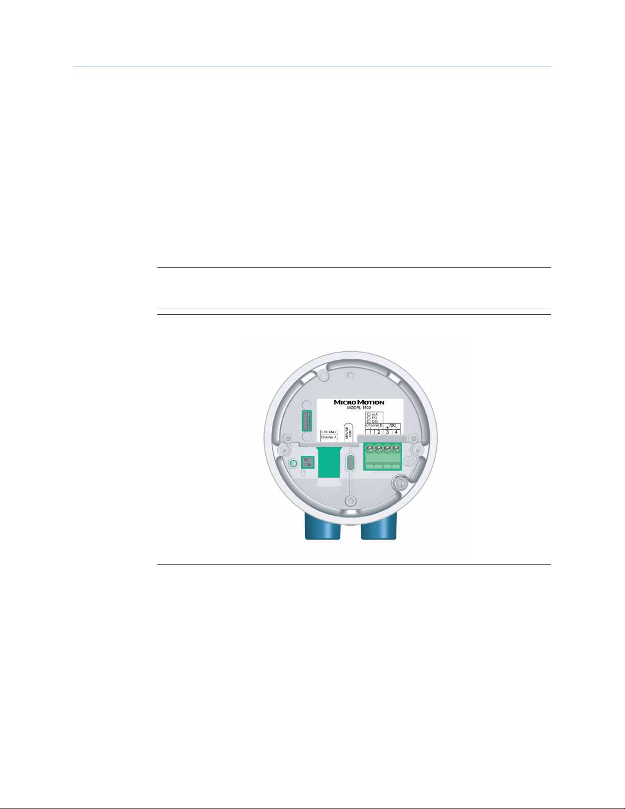
Figure 5-1: Location of power supply wiring terminals and equipment ground
Procedure
1. Remove the housing cover and the display, where applicable.
2. Connect the power supply wires.
For DC power, connect to terminals VDC (+) and VDC (-).
3. Tighten the two screws of the power connector to hold the wire.
Installation Manual 25

Power supply wiring Installation Manual
March 2022 00825-0100-1600
5.2 Wiring the Power over Ethernet (PoE) power
The transmitter supports both IEEE 802.3af and IEEE 802.3 standards for PoE. Use this
procedure if you are using PoE from Power Sourcing Equipment (PSE) through the
Ethernet cable.
Prerequisites
The PSE connecting to the 1600 transmitter must be labeled as compliant with either the
IEEE 802.3af standard or the IEEE 802.3at standard. Check the specific manufacturer's
specifications of any device to make sure it references IEEE 802.3 or it may not work with
the 1600 transmitter.
NOTICE
If the installation requires NAMUR NE-21 certification on the customer side, you should
use shielded Cat5e or shielded high-rated cables.
Note
The1600 transmitter belongs to PD (Power Device) Classification 3 in the IEEE 802.3af and
802.3at standards. If the installation uses Cat5e or Cat6 Ethernet cables, the transmitter
supports both Mode A and Mode B power delivery. If the installation uses D code M12
cables, the transmitter only supports Mode A power delivery.
WARNING
If the transmitter is in a hazardous area, do not remove the housing cover while the
transmitter is powered up. Failure to follow these instructions can cause an explosion
resulting in injury or death.
NOTICE
If both PoE and an external supply power is wired to VDC+, VDC-, the transmitter
automatically switches the power to the DC power input.
Procedure
1. Remove the housing cover and the display, where applicable.
2. Connect the PoE on Channel A (refer to Figure 5-2) using either a Cat5e cable or a
higher rated cable such as Cat6.
26 Micro Motion 1600 Ethernet Transmitters

Installation Manual Power supply wiring
00825-0100-1600 March 2022
Figure 5-2: Connecting the PoE on Channel A of the Transmitter
3. Because the Cat5e and higher-rated Ethernet cables are 360° bonded these cables
need to be grounded at the host end.
4. Replace the display where applicable, and the housing cover.
5.3 Wire the power supply using an M12terminated cable (optional)
Use this procedure if you are using an M12-terminated cable to wire the power supply.
Prerequisites
Obtain an A-coded M12-terminated cable.
Procedure
1. Attach the M12-terminated cable to the power connector on the 1600 transmitter.
Installation Manual 27

Power supply wiring Installation Manual
March 2022 00825-0100-1600
Figure 5-3: M12-terminated cables to the configuration I/O
Table 5-1: Cable end I/O pinouts
Pin
identification
Pin 1 Brown Pin3 VDC +
Pin 2 White Pin 1 Channel B +
Pin 3 Blue Pin 4 VDC -
Pin 4 Black Pin 2 Channel B -
Wire color Outputs on terminal Signal name
2. Attach the other cable end using the pinouts described in Table 5-2.
Note
For M12 power supply pinouts, only pins 1 and 3 are used.
Table 5-2: M12 power supply pinouts
Pin
identification
Pin 1 Brown Pin3 VDC +
Pin 2 White Pin 1 Channel B +
Pin 3 Blue Pin 4 VDC -
Pin 4 Black Pin 2 Channel B -
Wire color Outputs on terminal Signal name
28 Micro Motion 1600 Ethernet Transmitters

Installation Manual Set up the printer
00825-0100-1600 March 2022
6 Set up the printer
Use this section to set up printing with a 1600 Ethernet transmitter and an
Epson TM-T88VI Ethernet printer. For information on configuring the printer, see Micro
Motion 1600 Transmitters with Configurable Inputs and Outputs: Configuration and Use
Manual.
There are two ways to set up printing:
• Use the printer's default IP address
• Change the printer's default IP address
6.1 Set up the printer by changing the printer default IP address
Use this procedure to set up printing with a 1600 Ethernet transmitter and an Epson TMT88VI printer by changing the printer's default IP address.
Procedure
1. Connect one end of an Ethernet cable and power supply to the printer.
2. Connect the other end of the Ethernet cable to the PC.
3. Power on the printer.
The printer IP address prints after a few minutes.
4. Temporarily change the Ethernet address for the PC so that the Ethernet is on the
same subnet as the printer:
Default IP address = 192.168.192.168
a) From Windows 10, right-click the Start button and select Network
Connections.
b) Right-click the Ethernet connection and select Properties.
Select Yes on any user account pop-up windows.
c) Select Internet Protocol Version 4(TCP/IPv4), then select properties.
d) Select Use the following IP address and configure the IP address and subnet
mask as follows:
• IP address: 192.168.192.x, where x is something other than 0, 1, or 168
• Subnet mask: 255.255.255.0
e) Select OK.
5. Change the printer firmware options.
a) Open your web browser and type http://192.168.192.168 (default
printer IP).
The browser displays, Your connection is not private. Ignore the
warning and proceed to the website.
Installation Manual 29

Set up the printer Installation Manual
March 2022 00825-0100-1600
b) Select ADVANCED.
c) Select Proceed to 192.168.192.168.
d) At the login screen, enter:
Default username: epson
Default password: epson
The EpsonNet Config utility screen displays.
e) Select TCP/IP under the configuration settings (not the basic settings), listed
on the left side of the screen.
f) Change the IP Address (i.e., 192.168.1.55), Subnet Mask, and Default
Gateway based on your network. Select an IP address that is unique to the
local network.
The printer must be on the same subnet as the 1600.
g) Required: Set Acquiring the IP Address to Manual.
h) Select Send to save your settings.
i) Select Reset, or power cycle the printer when prompted to apply the
changes.
6. Change the PC network settings back to the original settings.
Use the windows you used in Step 4.
7. Configure the 1600 Ethernet transmitter for the printer.
a) Remove the Ethernet cable from the PC and connect it to the 1600 Ethernet
transmitter.
b) If you have not already done so, configure the transmitter IP address, subnet
mask, and default gateway.
Display
ProLink III Device Tools → Configuration → Network Settings
Menu → Configuration → Ethernet Settings →
Network Settings
For instructions on how to configure the transmitter and PC Ethernet
settings, see the Micro Motion 1600 with Ethernet Transmitters: Configuration
and Use Manual.
c) Enter the printer IP address you configured in the previous step into the 1600
Ethernet transmitter.
Display
Menu → Configuration → Printer → Printer IP
address
ProLink III Device Tools → Configuration → Printer and Tickets
Web browser Configuration → Printer and Tickets
30 Micro Motion 1600 Ethernet Transmitters

Installation Manual Set up the printer
00825-0100-1600 March 2022
8. Perform a test print to verify the settings are correct.
Display Menu → Operations → Printer → Print Ticket → Print Test
Page
ProLink III Device Tools → Configuration → Printer and Tickets
Web browser Configuration → Printer and Tickets
For instructions on how to configure print ticket options, see the Micro Motion 1600
with Ethernet Transmitters: Configuration and Use Manual.
If needed, see Function Check Failed in the Status alerts, causes, and recommendations
section of the Micro Motion 1600 with Ethernet Transmitters: Configuration and Use Manual.
6.2 Set up the printer using the printer default IP address
Use this procedure to set up printing with a 1600 Ethernet transmitter and an Epson TMT88VI printer using the printer's default IP address.
Procedure
1. Connect one end of an Ethernet cable and power supply to the printer.
2. Connect the other end of the Ethernet cable to the PC.
3. Power on the printer.
It can take 1-2 minutes for the printer to finish configuring network settings. When
complete, the following ticket prints.
*********************************
IP Address : 192.168.192.168
SubnetMask : 255.255.255.0
Gateway : 0.0.0.0 DHCP : No server - > Static
*********************************
4. Turn off DHCP if it is enabled.
From the display
a. Go to Menu → Configuration →
Ethernet Settings → Network Settings
→ Auto obtain IP()DHCP.
b. Select Disabled and Save.
c. Back out to the Ethernet Settings page
to apply the DHCP off setting.
From ProLink III
a. Go to Device Tools → Configuration →
Network Settings.
b. Uncheck Obtain an IP address
automatically (DHCP).
c. Select Apply.
Installation Manual 31

Set up the printer Installation Manual
March 2022 00825-0100-1600
5. Configure the IP address.
a) Navigate to one of the following screens:
From the display From ProLink III
Go to Menu → Configuration →
Ethernet Settings → Network Settings
→ IP address.
Go to Device Tools → Configuration →
Network Settings.
b) Set the IP address to 192.168.192.x, where x is something other than 0, 1,
or 168.
6. Configure the subnet mask.
a) Navigate to one of the following screens:
From the display From ProLink III
Go to Menu → Configuration →
Ethernet Settings → Network Settings
→ Subnet Mask.
Go to Device Tools → Configuration →
Network Settings.
b) Set the subnet mask to 255.255.255.0.
7. Configure the printer type.
a) Navigate to one of the following screens:
From the display
Go to Menu → Configuration → Printer
→ Printer Type.
From ProLink III
Go to Device Tools → Configuration →
Printer and Tickets.
b) Verify that the IP address is 192.168.192.168.
6.3 Reset the interface settings
Use this procedure if you forgot the IP address of your printer and need to reset the default
(192.168.192.168).
Procedure
1. Turn off the printer and close the roll paper cover.
2. If the connector cover is attached, remove the cover.
3. Hold down the status sheet button on the back of the printer while turning on the
printer.
A message displays indicating that resetting is being performed.
4. Release the status sheet button to reset the printer settings to default.
Important
Do not turn off power until the process is complete.
32 Micro Motion 1600 Ethernet Transmitters

Installation Manual Set up the printer
00825-0100-1600 March 2022
When complete, a Resetting to Factory Default Finished message
displays.
6.4 Function Check Failed
A functional check alert is commonly triggered due to the following conditions:
• Incorrect network settings configuration
• Out of paper
• Paper tray is open
• Printer already has six open connections
• Another transmitter tries to start a print while another transmitter is printing
Configuration items and audit log tickets can take more than 15 minutes to print and
use up paper. If during this time another transmitter starts a print, the new print may
either be rejected, causing a functional check alert (printer offline), or the print will be
inserted in the middle of the configuration/audit log print.
The functional check alert is cleared after a successful print.
Installation Manual 33

Set up the printer Installation Manual
March 2022 00825-0100-1600
34 Micro Motion 1600 Ethernet Transmitters

Installation Manual Power up the transmitter
00825-0100-1600 March 2022
7 Power up the transmitter
The transmitter must be powered up for all configuration and commissioning tasks, or for
process measurement.
Procedure
1. WARNING
If the transmitter is in a hazardous area, do not remove the housing cover while
the transmitter is powered up. Failure to follow these instructions can cause an
explosion resulting in injury or death.
Ensure that all transmitter and sensor covers and seals are closed.
2. Turn on the electrical power at the power supply.
The transmitter will automatically perform diagnostic routines. When using DC
power, a minimum of 1.5 amps of startup current is required. During this period,
Alert 009 is active. The diagnostic routines should complete in approximately
30 seconds. The status LED will turn green and begin to flash when the startup
diagnostics are complete. If the status LED exhibits different behavior, an alert is
active.
Postrequisites
Although the sensor is ready to receive process fluid shortly after power-up, the
electronics can take up to 10 minutes to reach thermal equilibrium. Therefore, if this is the
initial startup, or if power has been off long enough to allow components to reach ambient
temperature, allow the electronics to warm up for approximately 10 minutes before
relying on process measurements. During this warm-up period, you may observe minor
measurement instability or inaccuracy.
Installation Manual 35

Power up the transmitter Installation Manual
March 2022 00825-0100-1600
36 Micro Motion 1600 Ethernet Transmitters

Installation Manual Guided setup
00825-0100-1600 March 2022
8 Guided setup
At initial startup of the transmitter, the guided configuration screen appears on the
transmitter display. This tool guides you through basic configuration of the transmitter.
The guided setup allows you to upload configuration files, set the transmitter display
options, configure channels, and review sensor calibration data.
Installation Manual 37

Guided setup Installation Manual
March 2022 00825-0100-1600
38 Micro Motion 1600 Ethernet Transmitters

Installation Manual Components of the transmitter display
00825-0100-1600 March 2022
9 Components of the transmitter
display
The transmitter display includes two status LEDs, a multi-line LCD panel, and four
membrane arrow keys — left, up, down, and right — used to access the display menus and
navigate the display screens.
Figure 9-1: 1600 transmitter display
A. Status LED
B. LCD Display
Status LEDs
The status LEDs indicate the current state of the transmitter (STATUS) and the current
state of the Ethernet network (NET). From the display, the symbol “√” on the right side is
the transmitter status LED. The symbol “NET” on the left side is the network status LED.
The 1600 status LED supports NE107 mode. For configuration information, see the Micro
Motion 1600 with Ethernet Transmitters: Configuration and Use Manual.
Installation Manual 39

Components of the transmitter display Installation Manual
March 2022 00825-0100-1600
Table 9-1: Status LED and device status (MMI mode)
Status LED condition Device status
Solid green No alerts are active.
Solid yellow One or more alerts are active with Alert Severity = Out of
Specification, Maintenance Required, or Function Check.
Solid red One or more alerts are active with Alert Severity = Failure.
Flashing yellow (1 Hz) The Function Check in Progress alert is active.
Table 9-2: Network status LED and Ethernet network connection status
Network status LED condition Network status
Flashing green No connections made with primary protocol host.
Solid green Connection made with primary protocol host.
Flashing red Connection from primary protocol host has timed out.
Solid red Address Conflict Detection (ACD) algorithm has detected a
duplicate IP address.
LCD panel
In normal operation, the LCD panel shows the current value of the display variables, and
their measurement units.
The LCD panel also provides access to the display menus and alert information. From the
display menus, you can:
• View the current configuration and make configuration changes.
• Perform procedures such as loop testing and zero verification.
• Run batches.
The alert information allows you to see which alerts are active, acknowledge the alerts
individually or as a group, and to see more detailed information for individual alerts.
9.1 Access and use the display menus
The display menus allow you to perform most configuration, administration, and
maintenance tasks.
The four switches, ⇦⇧⇩⇨, are used to navigate the menus, make selections, and enter
data.
Procedure
1. Observe the action bar at the bottom of the LCD panel.
The action bar displays Menu⇨.
2. Press your thumb or finger over the ⇨ membrane switch to activate it.
The top-level menu is displayed.
40 Micro Motion 1600 Ethernet Transmitters

Installation Manual Components of the transmitter display
00825-0100-1600 March 2022
3. Navigate the menus using the four membrane switches:
• Activate ⇧ or ⇩ to scroll to the previous or next item in the menu.
• Activate and hold ⇧ or ⇩ (approximately 1 second) to scroll rapidly through
numbers or menu options.
• Activate ⇨ to drill down to a lower menu or to select an option.
• Activate and hold ⇨ to save and apply your action.
• Activate ⇦ to return to the previous menu.
• Activate and hold ⇦ to cancel your action.
The action bar is updated with context-sensitive information. The ⇨ and ⇦ symbols
indicate the associated membrane switch.
If the menu or the topic is too large for a single display screen, the ⇩ and ⇧ symbols
at the bottom and top of the LCD panel are used to indicate that you must scroll
down or up to see more information.
Figure 9-2: Navigation arrows
4. If you make a menu choice that leads back to the main menu, or changes to certain
procedures such as zero calibration:
• If display security is not enabled, the display prompts you to activate ⇦⇩⇨, in
that order. This feature protects against accidental changes to configuration,
but does not provide any security.
Installation Manual 41

Components of the transmitter display Installation Manual
March 2022 00825-0100-1600
Figure 9-3: Security prompts
• If display security is enabled, the display prompts you to enter the display
password.
5. If you make a menu choice that requires entering a numeric value or character
string, the display provides a screen similar to the following:
42 Micro Motion 1600 Ethernet Transmitters

Installation Manual Components of the transmitter display
00825-0100-1600 March 2022
Figure 9-4: Numeric values and character strings
• Activate ⇦ or ⇨ to position the cursor.
• Activate ⇧ and ⇩ to scroll through the values that are valid for that position.
• Repeat until all characters are set.
• Activate and hold ⇨ to save the value.
6. To exit the display menu system, use either of the following methods:
• Wait until the menu times out and returns to the display variables.
• Exit each menu separately, working your way back to the top of the menu
system.
Installation Manual 43

Components of the transmitter display Installation Manual
March 2022 00825-0100-1600
44 Micro Motion 1600 Ethernet Transmitters

Installation Manual Available service port connection
00825-0100-1600 March 2022
10 Available service port connection
Use the service port connection to download or upload data from/to the transmitter.
To access the service port, you can use the following signal converter to connect to the
service port terminals:
• USB to USB Type C
WARNING
If the transmitter is in a hazardous area, do not remove the housing cover while the
transmitter is powered up. Failure to follow these instructions can cause an explosion
resulting in injury or death.
Installation Manual 45

Available service port connection Installation Manual
March 2022 00825-0100-1600
46 Micro Motion 1600 Ethernet Transmitters

F3
C A
IEC 127-2
J3
DISC
OUT 3
T5A 250V
C A
F1
C A
IEC 127-2
J1
J4
DS1
T5A 250V
K3 K2 K1
A B C
DISC
OUT 2
IEC 127-2
F2 T5A 250V
J2
DS2
DISC
OUT 1
DS3
C18
C16
C14
A14
Installation Manual Wire the 1600 to the 3100 relays
00825-0100-1600 March 2022
A Wire the 1600 to the 3100 relays
Use this procedure to wire the Discrete Output on the 1600 Ethernet transmitter to the
3100 transmitter relays for single-stage batch control.
Prerequisites
• Set up the Channel B configuration to DO before wiring
• Use active high and internal power.
• Use wire size 24 AWG (0,25 mm2) to 16 AWG (1,5 mm2).
Procedure
1. Wire the negative terminal on Channel B from the 1600 Ethernet transmitter to
A14.
2. Wire the positive terminal on Channel B from the 1600 Ethernet transmitter to
either C14, C16, or C18.
Figure A-1: Wiring for 1600 Ethernet Channel B DO to 3100 relays
Installation Manual 47

*00825-0100-1600*
00825-0100-1600
Rev. AB
2022
For more information:
©
2022 Micro Motion, Inc. All rights reserved.
The Emerson logo is a trademark and service mark of Emerson
Electric Co. Micro Motion, ELITE, ProLink, MVD and MVD Direct
Connect marks are marks of one of the Emerson Automation
Solutions family of companies. All other marks are property of
their respective owners.
www.emerson.com
 Loading...