


Configuration and Use Manual
MMI-20019023, Rev AC
Micro Motion™ 1500 Transmitters with
Analog Outputs
Configuration and Use Manual
February 2022

Safety messages
Safety messages are provided throughout this manual to protect personnel and equipment. Read each safety message carefully
before proceeding to the next step.
Safety and approval information
This Micro Motion product complies with all applicable European directives when properly installed in accordance with the
instructions in this manual. Refer to the EU declaration of conformity for directives that apply to this product. The following are
available: the EU declaration of conformity, with all applicable European directives, and the complete ATEX Installation Drawings
and Instructions. In addition the IECEx Installation Instructions for installations outside of the European Union and the CSA
Installation Instructions for installations in North America are available on the internet at or through your local Micro Motion
support center.
Information affixed to equipment that complies with the Pressure Equipment Directive, can be found on the internet at . For
hazardous installations in Europe, refer to standard EN 60079-14 if national standards do not apply.
Other information
Full product specifications can be found in the product data sheet. Troubleshooting information can be found in the configuration
manual. Product data sheets and manuals are available from the Micro Motion web site at www.emerson.com.
Return policy
Follow Micro Motion procedures when returning equipment. These procedures ensure legal compliance with government
transportation agencies and help provide a safe working environment for Micro Motion employees. Micro Motion will not accept
your returned equipment if you fail to follow Micro Motion procedures.
Return procedures and forms are available on our web support site at www.emerson.com, or by phoning the Micro Motion
Customer Service department.
Emerson Flow customer service
Email:
• Worldwide: flow.support@emerson.com
• Asia-Pacific: APflow.support@emerson.com
Telephone:
North and South America
United States 800-522-6277 U.K. and Ireland 0870 240 1978 Australia 800 158 727
Canada +1 303-527-5200 The Netherlands +31 (0) 70 413
Mexico +52 55 5809 5010 France +33 (0) 800 917
Argentina +54 11 4809 2700 Germany 0800 182 5347 Pakistan 888 550 2682
Brazil +55 15 3413 8000 Italy +39 8008 77334 China +86 21 2892 9000
Chile +56 2 2928 4800 Central & Eastern +41 (0) 41 7686
Peru +51 15190130 Russia/CIS +7 495 995 9559 South Korea +82 2 3438 4600
Europe and Middle East Asia Pacific
New Zealand 099 128 804
6666
India 800 440 1468
901
Japan +81 3 5769 6803
111
Egypt 0800 000 0015 Singapore +65 6 777 8211
Oman 800 70101 Thailand 001 800 441 6426
Qatar 431 0044 Malaysia 800 814 008
Kuwait 663 299 01
South Africa 800 991 390
Saudi Arabia 800 844 9564
UAE 800 0444 0684
2

Configuration and Use Manual Contents
MMI-20019023 February 2022
Contents
Part I Getting started
Chapter 1 Before you begin........................................................................................................9
1.1 About this manual....................................................................................................................... 9
1.2 Transmitter model code.............................................................................................................. 9
1.3 Communications tools and protocols.......................................................................................... 9
1.4 Additional documentation and resources.................................................................................. 10
Chapter 2 Quick start............................................................................................................... 11
2.1 Power up the transmitter...........................................................................................................11
2.2 Check meter status....................................................................................................................11
2.3 Make a startup connection to the transmitter............................................................................12
2.4 (Optional) Adjust digital communications settings.................................................................... 12
2.5 Verify mass flow measurement..................................................................................................13
2.6 Verify the zero........................................................................................................................... 13
Part II Configuration and commissioning
Chapter 3 Introduction to configuration and commissioning....................................................17
3.1 Configuration flowchart.............................................................................................................17
3.2 Default values and ranges.......................................................................................................... 18
3.3 Disable write-protection on the transmitter configuration.........................................................18
3.4 Restore the factory configuration.............................................................................................. 18
Chapter 4 Configure process measurement..............................................................................19
4.1 Configure mass flow measurement........................................................................................... 19
4.2 Configure volume flow measurement for liquid applications..................................................... 23
4.3 Configure GSV flow measurement.............................................................................................27
4.4 Configure Flow Direction .......................................................................................................... 33
4.5 Configure density measurement ...............................................................................................38
4.6 Configure temperature measurement....................................................................................... 42
4.7 Configure pressure compensation............................................................................................. 43
Chapter 5 Configure device options and preferences................................................................ 49
5.1 Configure response time parameters.........................................................................................49
5.2 Configure alert handling............................................................................................................ 51
5.3 Configure informational parameters..........................................................................................55
Chapter 6 Integrate the meter with the control system............................................................ 59
6.1 Configure the transmitter channels........................................................................................... 59
Configuration and Use Manual 3

Contents Configuration and Use Manual
February 2022 MMI-20019023
6.2 Configure the mA Output.......................................................................................................... 59
6.3 Configure the Frequency Output............................................................................................... 65
6.4 Configure the Discrete Output...................................................................................................68
6.5 Configure events....................................................................................................................... 72
6.6 Configure digital communications.............................................................................................74
Chapter 7 Complete the configuration..................................................................................... 83
7.1 Test or tune the system using sensor simulation........................................................................83
7.2 Back up transmitter configuration............................................................................................. 85
7.3 Enable write-protection on the transmitter configuration..........................................................85
Part III Operations, maintenance, and troubleshooting
Chapter 8 Transmitter operation..............................................................................................89
8.1 Record the process variables......................................................................................................89
8.2 View process variables............................................................................................................... 89
8.3 View transmitter status using the status LED............................................................................. 90
8.4 View and acknowledge status alerts.......................................................................................... 90
8.5 Read totalizer and inventory values............................................................................................92
8.6 Start and stop totalizers and inventories.................................................................................... 92
8.7 Reset totalizers.......................................................................................................................... 93
8.8 Reset inventories....................................................................................................................... 93
Chapter 9 Measurement support..............................................................................................95
9.1 Options for measurement support.............................................................................................95
9.2 Use Smart Meter Verification..................................................................................................... 95
9.3 Use Production Volume Reconciliation, Transient Mist Remediation, and Transient Bubble
Remediation............................................................................................................................. 101
9.4 Piecewise linearization (PWL) for calibrating gas meters.......................................................... 102
9.5 Zero the meter........................................................................................................................ 102
9.6 Validate the meter...................................................................................................................103
9.7 Perform a (standard) D1 and D2 density calibration.................................................................105
9.8 Perform a D3 and D4 density calibration (T-Series sensors only).............................................. 107
9.9 Perform temperature calibration............................................................................................. 110
Chapter 10 Troubleshooting.................................................................................................... 113
10.1 Status LED states................................................................................................................... 113
10.2 Check the core processor LED................................................................................................ 113
10.3 Perform a 700 core processor resistance test.........................................................................115
10.4 Check the cutoffs...................................................................................................................116
10.5 Density measurement problems............................................................................................116
10.6 Check the drive gain.............................................................................................................. 117
10.7 Check for internal electrical problems....................................................................................118
10.8 Check Flow Direction ............................................................................................................ 120
4 Micro Motion 1500 Transmitters with Analog Outputs

Configuration and Use Manual Contents
MMI-20019023 February 2022
10.9 Flow measurement problems ................................................................................................121
10.10 Frequency Output problems................................................................................................123
10.11 Check Frequency Output Fault Action .................................................................................123
10.12 Check Frequency Output Scaling Method ........................................................................... 124
10.13 Check grounding................................................................................................................. 124
10.14 Check the HART communication loop................................................................................. 124
10.15 Check HART Address and mA Output Action........................................................................125
10.16 Check HART burst mode......................................................................................................125
10.17 Perform loop tests............................................................................................................... 125
10.18 Check Lower Range Value and Upper Range Value ..............................................................128
10.19 Milliamp output problems................................................................................................... 128
10.20 Check mA Output Fault Action ............................................................................................130
10.21 Check the trimming of the mA Output.................................................................................130
10.22 Check the pickoff voltage.................................................................................................... 130
10.23 Check power supply wiring.................................................................................................. 131
10.24 Check for radio frequency interference (RFI)........................................................................ 132
10.25 Using sensor simulation for troubleshooting....................................................................... 132
10.26 Check sensor-to-transmitter wiring..................................................................................... 132
10.27 Check for two-phase flow (slug flow)................................................................................... 133
10.28 Status alerts, causes, and recommendations....................................................................... 133
10.29 Temperature measurement problems.................................................................................148
Appendix A Using ProLink III with the transmitter.....................................................................151
A.1 Basic information about ProLink III ..........................................................................................151
A.2 Connect with ProLink III .......................................................................................................... 152
Appendix B Using a field communicator with the transmitter................................................... 161
B.1 Basic information about field communicators..........................................................................161
B.2 Connect with a field communicator ........................................................................................ 162
Appendix C Default values and ranges...................................................................................... 165
Appendix D Transmitter components and installation wiring.................................................... 171
D.1 Installation types.....................................................................................................................171
D.2 Power supply terminals .......................................................................................................... 173
D.3 Input/output (I/O) wiring terminals......................................................................................... 174
Appendix E NE 53 history..........................................................................................................175
Configuration and Use Manual 5

Contents Configuration and Use Manual
February 2022 MMI-20019023
6 Micro Motion 1500 Transmitters with Analog Outputs

Configuration and Use Manual Getting started
MMI-20019023 February 2022
Part I
Getting started
Configuration and Use Manual 7

Getting started Configuration and Use Manual
February 2022 MMI-20019023
8 Micro Motion 1500 Transmitters with Analog Outputs

Configuration and Use Manual Before you begin
MMI-20019023 February 2022
1 Before you begin
1.1 About this manual
This manual helps you configure, commission, use, maintain, and troubleshoot the 1500 transmitter.
Important
This manual assumes that:
• The transmitter has been installed correctly and completely according to the instructions in the
transmitter installation manual
• Users understand basic transmitter and sensor installation, configuration, and maintenance concepts and
procedures
1.2 Transmitter model code
You can verify that this manual pertains to your transmitter by ensuring the model code on the transmitter
tag matches the format.
Example:
The transmitter has a model number of the following form: 1500DEB**A******
D
4-wire remote DIN rail–mount
E
4-wire remote DIN rail transmitter with 9-wire remote enhanced core processor
B
4-wire remote DIN rail transmitter with 9-wire remote core processor
A
Analog outputs option board
1.3 Communications tools and protocols
You must have a communications tool to interface with the transmitter. Several different communications
tools and protocols are supported. You may use different tools in different locations or for different tasks.
Communications tool
ProLink III • HART/Bell 202
Field communicator • HART/Bell 202
Tip
You may be able to use other communications tools, such as AMS™ Suite: Intelligent Device Manager, or the
Smart Wireless THUM™ Adapter. Use of AMS or the Smart Wireless THUM Adapter is not discussed in this
manual. For more information on the Smart Wireless THUM Adapter, refer to the documentation available at .
Supported protocols
• Modbus/RS-485
• Service port
Configuration and Use Manual 9

Before you begin Configuration and Use Manual
February 2022 MMI-20019023
1.4 Additional documentation and resources
The following additional documentation supports the installation and operation of the transmitter.
Topic Document
Hazardous area installation See the approval documentation shipped with the
transmitter, or download the appropriate documentation
at www.emerson.com.
Product Data Sheet
Production Volume Reconciliation (PVR), Transient Bubble
Remediation (TBR), and Transient Mist Remediation (TMR)
applications
Sensor Sensor documentation
Transmitter installation
Micro Motion Series 1000 and Series 2000 Transmitters with
MVD™ Technology Product Data Sheet (PDS)
Micro Motion Oil and Gas Production Supplement
Micro Motion Model 1500 and Model 2500 Transmitters:
Installation Manual
All documentation resources are available at www.emerson.com or on the user documentation DVD.
10 Micro Motion 1500 Transmitters with Analog Outputs

Configuration and Use Manual Quick start
MMI-20019023 February 2022
2 Quick start
2.1 Power up the transmitter
The transmitter must be powered up for all configuration and commissioning tasks, or for process
measurement.
The 1500:
• Is DC powered only
• Has a minimum 19.2 to 28.8 VDC, 6.3 watts
• At startup, the transmitter power source must provide a minimum of 1.0 amperes of short-term current
per transmitter
• The length and conductor diameter of the power cable must be sized to provide 19.2 VDC minimum at the
power terminals, at a load current of 330 mA
Procedure
1. Ensure that all transmitter and sensor covers and seals are closed.
WARNING
To prevent ignition of flammable or combustible atmospheres, ensure that all covers and seals are
tightly closed. For hazardous area installations, applying power while housing covers are removed or
loose can cause an explosion.
2. Turn on the electrical power at the power supply.
The transmitter will automatically perform diagnostic routines. During this period, Alert 009 is active.
The diagnostic routines should complete in approximately 30 seconds. The status LED will turn green
when the startup diagnostics are complete. If the status LED exhibits different behavior, an alert is
active.
Postrequisites
Although the sensor is ready to receive process fluid shortly after power-up, the electronics can take up to
10 minutes to reach thermal equilibrium. Therefore, if this is the initial startup, or if power has been off long
enough to allow components to reach ambient temperature, allow the electronics to warm up for
approximately 10 minutes before relying on process measurements. During this warm-up period, you may
observe minor measurement instability or inaccuracy.
2.2 Check meter status
Check the meter for any error conditions that require user action or that affect measurement accuracy.
Procedure
1. Wait approximately 10 seconds for the power-up sequence to complete.
Immediately after power-up, the transmitter runs through diagnostic routines and checks for error
conditions. During the power-up sequence, Alert A009 is active. This alert should clear automatically
when the power-up sequence is complete.
Configuration and Use Manual 11

Quick start Configuration and Use Manual
February 2022 MMI-20019023
2. Check the status LED on the transmitter.
Related information
View and acknowledge status alerts
2.2.1 Transmitter status reported by LED
Table 2-1: Status LED states
LED state Alarm condition Description
Solid green No alarm Normal operation
Flashing yellow No alarm • Zero calibration procedure is in progress
• Loop test is in progress
Solid yellow Low-severity alarm Alarm condition that will not cause measurement error
(outputs continue to report process data)
Solid red High-severity alarm Alarm condition that will cause measurement error
(outputs in fault)
2.3 Make a startup connection to the transmitter
To configure the transmitter, you must have an active connection from a communications tool. Follow this
procedure to make your first connection to the transmitter.
Procedure
Identify the connection type to use, and follow the instructions for that connection type in the appropriate
appendix. Use the default communications parameters shown in the appendix.
Communications tool
ProLink III Modbus/RS-485 Using ProLink III with the transmitter
Field Communicator HART Using a field communicator with the
Connection type to use Instructions
transmitter
2.4 (Optional) Adjust digital communications settings
Change the communications parameters to site-specific values.
Important
If you are changing communications parameters for the connection type that you are using, you will lose the
connection when you write the parameters to the transmitter. Reconnect using the new parameters.
Procedure
1. To change the communications parameters using ProLink III, choose Device Tools → Configuration →
Communications.
2. To change the communications parameters using the Field Communicator, choose On-Line Menu →
Configure → Manual Setup → Inputs/Outputs → Communications.
12 Micro Motion 1500 Transmitters with Analog Outputs

Configuration and Use Manual Quick start
MMI-20019023 February 2022
2.5 Verify mass flow measurement
Check to see that the mass flow rate reported by the transmitter is accurate. You can use any available
method.
Procedure
• Connect to the transmitter with ProLink III and read the value for Mass Flow Rate in the Process Variables
panel.
• Connect to the transmitter with a field communicator and read the value for Mass Flow Rate.
Online → Overview → Mass Flow Rate
Postrequisites
If the reported mass flow rate is not accurate:
• Check the characterization parameters.
• Review the troubleshooting suggestions for flow measurement issues.
2.6 Verify the zero
Verifying the zero helps you determine if the stored zero value is appropriate to your installation, or if a field
zero can improve measurement accuracy.
The zero verification procedure analyzes the Live Zero value under conditions of zero flow, and compares it to
the Zero Stability range for the sensor. If the average Live Zero value is within a reasonable range, the zero
value stored in the transmitter is valid. Performing a field calibration will not improve measurement accuracy.
Important
In most cases, the factory zero is more accurate than the field zero. Do not zero the meter unless one of the
following is true:
• The zero is required by site procedures.
• The stored zero value fails the zero verification procedure.
Do not verify the zero or zero the meter if a high-severity alert is active. Correct the problem, then verify the
zero or zero the meter. You may verify the zero or zero the meter if a low-severity alert is active.
Procedure
1. Allow the flowmeter to warm up for at least 20 minutes after applying power.
2. Run the process fluid through the sensor until the sensor temperature reaches the normal process
operating temperature.
3. Stop flow through the sensor by shutting the downstream valve, and then the upstream valve if
available.
4. Verify that the sensor is blocked in, that flow has stopped, and that the sensor is completely full of
process fluid.
5. From ProLink III, choose Device Tools → Calibration → Zero Verification and Calibration → Verify
Zero and wait until the procedure completes.
6. Observe the drive gain, temperature, and density readings. If they are stable, check the Live Zero or
Field Verification Zero value. If the average value is close to 0, you should not need to zero the meter.
Configuration and Use Manual 13

Quick start Configuration and Use Manual
February 2022 MMI-20019023
7. If the zero verification procedure fails:
a) Confirm that the sensor is completely blocked in, that flow has stopped, and that the sensor is
completely full of process fluid.
b) Verify that the process fluid is not flashing or condensing, and that it does not contain particles
that can settle out.
c) Remove or reduce sources of electromechanical noise if appropriate.
d) Repeat the zero verification procedure.
e) If it fails again, zero the meter.
Postrequisites
Restore normal flow through the sensor by opening the valves.
Related information
Zero the meter
2.6.1 Terminology used with zero verification and zero calibration
Term Definition
Zero In general, the offset required to synchronize the left pickoff and the right pickoff under
conditions of zero flow. Unit = microseconds.
Factory Zero The zero value obtained at the factory, under laboratory conditions.
Field Zero The zero value obtained by performing a zero calibration outside the factory.
Prior Zero The zero value stored in the transmitter at the time a field zero calibration is begun. May
be the factory zero or a previous field zero.
Manual Zero The zero value stored in the transmitter, typically obtained from a zero calibration
procedure. It may also be configured manually. Also called “mechanical zero” or “stored
zero”.
Live Zero The real-time bidirectional mass flow rate with no flow damping or mass flow cutoff
applied. An adaptive damping value is applied only when the mass flow rate changes
dramatically over a very short interval. Unit = configured mass flow measurement unit.
Zero Stability A laboratory-derived value used to calculate the expected accuracy for a sensor. Under
laboratory conditions at zero flow, the average flow rate is expected to fall within the
range defined by the Zero Stability value (0 ± Zero Stability). Each sensor size and model
has a unique Zero Stability value.
Zero Calibration The procedure used to determine the zero value.
Zero Time The time period over which the Zero Calibration procedure is performed. Unit = seconds.
Field Verification Zero A 3-minute running average of the Live Zero value, calculated by the transmitter. Unit =
configured mass flow measurement unit.
Zero Verification A procedure used to evaluate the stored zero and determine whether or not a field zero
can improve measurement accuracy.
14 Micro Motion 1500 Transmitters with Analog Outputs

Configuration and Use Manual Configuration and commissioning
MMI-20019023 February 2022
Part II
Configuration and commissioning
Configuration and Use Manual 15

Configuration and commissioning Configuration and Use Manual
February 2022 MMI-20019023
16 Micro Motion 1500 Transmitters with Analog Outputs

Configuration and Use Manual Introduction to configuration and commissioning
MMI-20019023 February 2022
3 Introduction to configuration and commissioning
3.1 Configuration flowchart
Use the following flowchart as a general guide to the configuration and commissioning process.
Some options may not apply to your installation. Detailed information is provided in the remainder of this
manual.
Configure process measurement
Configure mass flow
measurement
Configure device options and
preferences
Configure fault handling
parameters
Test and move to production
Test or tune transmitter
using sensor simulation
Configure volume flow
meaurement
Volume flow type
Liquid
Configure flow direction
Configure density
measurement
Configure temperature
measurement
Configure pressure
compensation (optional)
Configure PVR, TMR,
or TBR (if available)
Gas
Define gas properties
Configure sensor
parameters
Configure device
parameters
Integrate device with control system
Configure the channel(s)
Configure the mA
output(s)
Configure the frequency
output(s)
Configure the discrete
output(s)
Back up transmitter
configuration
Enable write-protection on
transmitter configuration
Done
Configure events
Configure digital
communications
Configuration and Use Manual 17

Introduction to configuration and commissioning Configuration and Use Manual
February 2022 MMI-20019023
3.2 Default values and ranges
See Default values and ranges to view the default values and ranges for the most commonly used parameters.
3.3 Disable write-protection on the transmitter
configuration
Display OFF-LINE MAINT → CONFG → LOCK
ProLink III Device Tools → Configuration → Write-Protection
If the transmitter is write-protected, the configuration is locked and you must unlock it before you can change
any configuration parameters. By default, the transmitter is not write-protected.
Tip
Write-protecting the transmitter prevents accidental changes to configuration. It does not prevent normal
operational use. You can always disable write-protection, perform any required configuration changes, then
re-enable write-protection.
3.4 Restore the factory configuration
ProLink III Device Tools → Configuration Transfer → Restore Factory Configuration
Field communicator Service Tools → Maintenance → Reset/Restore → Restore Factory Configuration
Restoring the factory configuration returns the transmitter to the same configuration it had when it left the
factory. This may be useful if you experience problems during configuration.
Important
You cannot restore factory configurations with a 700 core.
Tip
Restoring the factory configuration is not a common action. You may want to contact customer support to
see if there is a preferred method to resolve any issues.
18 Micro Motion 1500 Transmitters with Analog Outputs

Configuration and Use Manual Configure process measurement
MMI-20019023 February 2022
4 Configure process measurement
4.1 Configure mass flow measurement
The mass flow measurement parameters control how mass flow is measured and reported.
4.1.1 Configure Mass Flow Measurement Unit
ProLink III Device Tools → Configuration → Process Measurement → Flow
Field Communicator Configure → Manual Setup → Measurements → Flow → Mass Flow Unit
Mass Flow Measurement Unit specifies the unit of measure that will be used for the mass flow rate. The unit
used for mass total and mass inventory is derived from this unit.
Any selected measurement unit, (mass, volume or gas standard volume), is automatically applied to both the
mA and Frequency Outputs.
Procedure
Set Mass Flow Measurement Unit to the unit you want to use.
The default setting for Mass Flow Measurement Unit is g/sec (grams per second).
Tip
If the measurement unit you want to use is not available, you can define a special measurement unit.
Options for Mass Flow Measurement Unit
The transmitter provides a standard set of measurement units for Mass Flow Measurement Unit, plus one
user-defined special measurement unit. Different communications tools may use different labels for the
units.
Label
Unit description
Grams per second g/sec g/s
Grams per minute g/min g/min
Grams per hour g/hr g/h
Kilograms per second kg/sec kg/s
Kilograms per minute kg/min kg/min
Kilograms per hour kg/hr kg/h
ProLink III Field Communicator
Kilograms per day kg/day kg/d
Metric tons per minute mTon/min MetTon/min
Metric tons per hour mTon/hr MetTon/h
Metric tons per day mTon/day MetTon/d
Pounds per second lbs/sec lb/s
Configuration and Use Manual 19

Configure process measurement Configuration and Use Manual
February 2022 MMI-20019023
Label
Unit description
Pounds per minute lbs/min lb/min
Pounds per hour lbs/hr lb/h
Pounds per day lbs/day lb/d
Short tons (2000 pounds) per minute sTon/min STon/min
Short tons (2000 pounds) per hour sTon/hr STon/h
Short tons (2000 pounds) per day sTon/day STon/d
Long tons (2240 pounds) per hour lTon/hr LTon/h
Long tons (2240 pounds) per day lTon/day LTon/d
Special unit special Spcl
ProLink III Field Communicator
Define a special measurement unit for mass flow
ProLink III Device Tools → Configuration → Process Measurement → Flow → Special Units
Field Communicator Configure → Manual Setup → Measurements → Special Units → Mass Special Units
A special measurement unit is a user-defined unit of measure that allows you to report process data, totalizer
data, and inventory data in a unit that is not available in the transmitter. A special measurement unit is
calculated from an existing measurement unit using a conversion factor.
Procedure
1. Specify Base Mass Unit.
Base Mass Unit is the existing mass unit that the special unit will be based on.
2. Specify Base Time Unit.
Base Time Unit is the existing time unit that the special unit will be based on.
3. Calculate Mass Flow Conversion Factor as follows:
a) x base units = y special units
b) Mass Flow Conversion Factor = x ÷ y
The original mass flow rate value is divided by this value.
4. Enter Mass Flow Conversion Factor.
5. Set Mass Flow Label to the name you want to use for the mass flow unit.
6. Set Mass Total Label to the name you want to use for the mass total and mass inventory unit.
The special measurement unit is stored in the transmitter. You can configure the transmitter to use the
special measurement unit at any time.
Example: Defining a special measurement unit for mass flow
You want to measure mass flow in ounces per second (oz/sec).
1. Set Base Mass Unit to Pounds (lb).
20 Micro Motion 1500 Transmitters with Analog Outputs

Configuration and Use Manual Configure process measurement
MMI-20019023 February 2022
2. Set Base Time Unit to Seconds (sec).
3. Calculate Mass Flow Conversion Factor:
a. 1 lb/sec = 16 oz/sec
b. Mass Flow Conversion Factor = 1 ÷ 16 = 0.0625
4. Set Mass Flow Conversion Factor to 0.0625.
5. Set Mass Flow Label to oz/sec.
6. Set Mass Total Label to oz.
4.1.2 Configure Flow Damping
ProLink III Device Tools → Configuration → Process Measurement → Flow
Field Communicator Configure → Manual Setup → Measurements → Flow → Flow Damping
Damping is used to smooth out small, rapid fluctuations in process measurement. Damping Value specifies
the time period (in seconds) over which the transmitter will spread changes in the process variable. At the end
of the interval, the internal value will reflect 63% of the change in the actual measured value.
Procedure
Set Flow Damping to the value you want to use.
The default value is 0.8 seconds. The range depends on the core processor type and the setting of Update
Rate, as shown in the following table.
Update Rate setting
Normal 0 to 51.2 seconds
Special 0 to 40.96 seconds
Damping range
The value you enter is automatically rounded off to the nearest valid value. For example, if the damping is
currently set to 0.8 seconds, any value entered up to 1.2 seconds will be rounded down to 0.8 seconds, and
any value entered from 1.21 to 1.59 seconds will be rounded up to 1.6 seconds.
Update Rate setting
Normal 0.0, 0.2, 0.4, 0.8, 1.6, 3.2, 6.4, 12.8, 25.6, 51.2
Special 0.0, 0.04, 0.08, 0.16, 0.32, 0.64, 1.28, 2.56, 5.12, 10.24,
Valid damping values
20.48, 40.96
Configuration and Use Manual 21

Configure process measurement Configuration and Use Manual
February 2022 MMI-20019023
Effect of flow damping on volume measurement
Flow damping affects volume measurement for liquid volume data. Flow damping also affects volume
measurement for gas standard volume data. The transmitter calculates volume data from the damped mass
flow data.
Interaction between Flow Damping and mA Output Damping
In some circumstances, both Flow Damping and mA Output Damping are applied to the reported mass flow
value.
Flow Damping controls the rate of change in flow process variables. mA Output Damping controls the rate
of change reported through mA Output. If mA Output Process Variable is set to Mass Flow Rate, and both
Flow Damping and mA Output Damping are set to non-zero values, flow damping is applied first, and the
added damping calculation is applied to the result of the first calculation.
4.1.3 Configure Mass Flow Cutoff
ProLink III Device Tools → Configuration → Process Measurement → Flow
Field Communicator Configure → Manual Setup → Measurements → Flow → Mass Flow Cutoff
Mass Flow Cutoff specifies the lowest mass flow rate that will be reported as measured. All mass flow rates
below this cutoff will be reported as 0.
Procedure
Set Mass Flow Cutoff to the value you want to use.
The default value for Mass Flow Cutoff is 0.0 g/sec or a sensor-specific value set at the factory. The
recommended value is 0.5% of the nominal flow rate of the attached sensor. See the sensor specifications. Do
not leave Mass Flow Cutoff at 0.0 g/sec.
Effect of Mass Flow Cutoff on volume measurement
Mass Flow Cutoff does not affect volume measurement. Volume data is calculated from the actual mass data
rather than the reported value.
Volume flow has a separate Volume Flow Cutoff that is not affected by the Mass Flow Cutoff value.
Interaction between Mass Flow Cutoff and mA Output Cutoff
Mass Flow Cutoff defines the lowest mass flow value that the transmitter will report as measured. mA
Output Cutoff defines the lowest flow rate that will be reported through mA Output. If mA Output Process
Variable is set to Mass Flow Rate, the mass flow rate reported through mA Output is controlled by the higher
of the two cutoff values.
Mass Flow Cutoff affects all reported values and values used in other transmitter behavior (e.g., events
defined on mass flow).
mA Output Cutoff affects only mass flow values reported through mA Output.
22 Micro Motion 1500 Transmitters with Analog Outputs

Configuration and Use Manual Configure process measurement
MMI-20019023 February 2022
Example: Cutoff interaction with mA Output Cutoff lower than Mass Flow Cutoff
Configuration:
• mA Output Process Variable: Mass Flow Rate
• Frequency Output Process Variable: Mass Flow Rate
• mA Output Cutoff: 10 g/sec
• Mass Flow Cutoff: 15 g/sec
Result: If the mass flow rate drops below 15 g/sec, mass flow will be reported as 0, and 0 will be used in all
internal processing.
Example: Cutoff interaction with mA Output Cutoff higher than Mass Flow Cutoff
Configuration:
• mA Output Process Variable: Mass Flow Rate
• Frequency Output Process Variable: Mass Flow Rate
• mA Output Cutoff: 15 g/sec
• Mass Flow Cutoff: 10 g/sec
Result:
• If the mass flow rate drops below 15 g/sec but not below 10 g/sec:
— The mA Output will report zero flow.
— The Frequency Output will report the actual flow rate, and the actual flow rate will be used in all
internal processing.
• If the mass flow rate drops below 10 g/sec, both outputs will report zero flow, and 0 will be used in all
internal processing.
4.2 Configure volume flow measurement for liquid
applications
The volume flow measurement parameters control how liquid volume flow is measured and reported.
Restriction
You cannot implement both liquid volume flow and gas standard volume flow at the same time. Choose one
or the other.
Note
If you need to switch from gas standard volume to liquid volume, polling for base density will automatically be
disabled.
4.2.1 Configure Volume Flow Type for liquid applications
ProLink III
Field Communicator Configure → Manual Setup → Measurements → GSV → Volume Flow Type → Liquid
Configuration and Use Manual 23
Device Tools → Configuration → Process Measurement → Flow

Configure process measurement Configuration and Use Manual
February 2022 MMI-20019023
Volume Flow Type controls whether liquid or gas standard volume flow measurement will be used.
Restriction
Gas standard volume measurement is incompatible with some applications. Set Volume Flow Type to Liquid
if you are using any of the following applications:
• Production Volume Reconciliation (PVR)
Procedure
Set Volume Flow Type to Liquid.
4.2.2 Configure Volume Flow Measurement Unit for liquid
applications
ProLink III Device Tools → Configuration → Process Measurement → Flow
Field Communicator Configure → Manual Setup → Measurements → Flow → Volume Flow Unit
Volume Flow Measurement Unit specifies the unit of measurement that will be displayed for the volume
flow rate. The unit used for the volume total and volume inventory is based on this unit.
Prerequisites
Before you configure Volume Flow Measurement Unit, be sure that Volume Flow Type is set to Liquid.
Procedure
Set Volume Flow Measurement Unit to the unit you want to use.
To read US gallons, select that unit from this menu. G/MIN stands for grams per minute (USGPM), not gallons
per minute. The default setting for Volume Flow Measurement Unit is l/sec (liters per second).
Tip
If the measurement unit you want to use is not available, you can define a special measurement unit.
Options for Volume Flow Measurement Unit for liquid applications
The transmitter provides a standard set of measurement units for Volume Flow Measurement Unit, plus one
user-defined measurement unit. Different communications tools may use different labels for the units.
Label
Unit description
Cubic feet per second ft3/sec Cuft/s
Cubic feet per minute ft3/min Cuft/min
Cubic feet per hour ft3/hr Cuft/h
Cubic feet per day ft3/day Cuft/d
ProLink III Field Communicator
Cubic meters per second m3/sec Cum/s
Cubic meters per minute m3/min Cum/min
Cubic meters per hour m3/hr Cum/h
24 Micro Motion 1500 Transmitters with Analog Outputs

Configuration and Use Manual Configure process measurement
MMI-20019023 February 2022
Label
Unit description
ProLink III Field Communicator
Cubic meters per day m3/day Cum/d
U.S. gallons per second US gal/sec gal/s
U.S. gallons per minute US gal/min gal/min
U.S. gallons per hour US gal/hr gal/h
U.S. gallons per day US gal/day gal/d
Million U.S. gallons per day mil US gal/day MMgal/d
Liters per second l/sec L/s
Liters per minute l/min L/min
Liters per hour l/hr L/h
Million liters per day mil l/day ML/d
Imperial gallons per second Imp gal/sec Impgal/s
Imperial gallons per minute Imp gal/min Impgal/min
Imperial gallons per hour Imp gal/hr Impgal/h
Imperial gallons per day Imp gal/day Impgal/d
(1)
(1)
(1)
(1)
(2)
(2)
(2)
(2)
barrels/sec bbl/s
barrels/min bbl/min
barrels/hr bbl/h
barrels/day bbl/d
Beer barrels/sec bbbl/s
Beer barrels/min bbbl/min
Beer barrels/hr bbbl/h
Beer barrels/day bbbl/d
Barrels per second
Barrels per minute
Barrels per hour
Barrels per day
Beer barrels per second
Beer barrels per minute
Beer barrels per hour
Beer barrels per day
Special unit special Spcl
(1) Unit based on oil barrels (42 U.S. gallons).
(2) Unit based on U.S. beer barrels (31 U.S. gallons).
Define a special measurement unit for volume flow
ProLink III
Field Communicator Configure → Manual Setup → Measurements → Special Units → Volume Special Units
A special measurement unit is a user-defined unit of measure that allows you to report process data, totalizer
data, and inventory data in a unit that is not available in the transmitter. A special measurement unit is
calculated from an existing measurement unit using a conversion factor.
Note
Configuration and Use Manual 25
Device Tools → Configuration → Process Measurement → Flow → Special Units

Configure process measurement Configuration and Use Manual
February 2022 MMI-20019023
Procedure
1. Specify Base Volume Unit.
Base Volume Unit is the existing volume unit that the special unit will be based on.
2. Specify Base Time Unit.
Base Time Unit is the existing time unit that the special unit will be based on.
3. Calculate Volume Flow Conversion Factor as follows:
a) x base units = y special units
b) Volume Flow Conversion Factor = x ÷ y
4. Enter Volume Flow Conversion Factor.
The original volume flow rate value is divided by this conversion factor.
5. Set Volume Flow Label to the name you want to use for the volume flow unit.
6. Set Volume Total Label to the name you want to use for the volume total and volume inventory unit.
The special measurement unit is stored in the transmitter. You can configure the transmitter to use the
special measurement unit at any time.
Defining a special measurement unit for volume flow
You want to measure volume flow in pints per second (pints/sec).
1. Set Base Volume Unit to Gallons (gal).
2. Set Base Time Unit to Seconds (sec).
3. Calculate the conversion factor:
a. 1 gal/sec = 8 pints/sec
b. Volume Flow Conversion Factor = 1 ÷ 8 = 0.1250
4. Set Volume Flow Conversion Factor to 0.1250.
5. Set Volume Flow Label to pints/sec.
6. Set Volume Total Label to pints.
4.2.3 Configure Volume Flow Cutoff
ProLink III
Field Communicator Configure → Manual Setup → Measurements → Flow → Volume Flow Cutoff
Volume Flow Cutoff specifies the lowest volume flow rate that will be reported as measured. All volume flow
rates below this cutoff are reported as 0.
Device Tools → Configuration → Process Measurement → Flow
Procedure
Set Volume Flow Cutoff to the value you want to use.
The default value for Volume Flow Cutoff is 0.0 l/sec (liters per second). The lower limit is 0. Leaving the
volume flow cutoff at 0 is not recommended.
26 Micro Motion 1500 Transmitters with Analog Outputs

Configuration and Use Manual Configure process measurement
MMI-20019023 February 2022
Interaction between Volume Flow Cutoff and mAO Cutoff
Volume Flow Cutoff defines the lowest liquid volume flow value that the transmitter will report as measured.
mAO Cutoff defines the lowest flow rate that will be reported through mA Output. If mA Output Process
Variable is set to Volume Flow Rate, the volume flow rate reported through mA Output is controlled by the
higher of the two cutoff values.
Volume Flow Cutoff affects both the volume flow values reported via the outputs and the volume flow values
used in other transmitter behavior (e.g., events defined on the volume flow).
mAO Cutoff affects only flow values reported through mA Output.
Example: Cutoff interaction with mAO Cutoff lower than Volume Flow Cutoff
Configuration:
• mA Output Process Variable: Volume Flow Rate
• Frequency Output Process Variable: Volume Flow Rate
• AO Cutoff: 10 l/sec
• Volume Flow Cutoff: 15 l/sec
Result: If the volume flow rate drops below 15 l/sec, volume flow will be reported as 0, and 0 will be used in all
internal processing.
Example: Cutoff interaction with mAO Cutoff higher than Volume Flow Cutoff
Configuration:
• mA Output Process Variable: Volume Flow Rate
• Frequency Output Process Variable: Volume Flow Rate
• AO Cutoff: 15 l/sec
• Volume Flow Cutoff: 10 l/sec
Result:
• If the volume flow rate drops below 15 l/sec but not below 10 l/sec:
— The mA Output will report zero flow.
— The Frequency Output will report the actual flow rate, and the actual flow rate will be used in all
internal processing.
• If the volume flow rate drops below 10 l/sec, both outputs will report zero flow, and 0 will be used in all
internal processing.
4.3 Configure GSV flow measurement
The gas standard volume (GSV) flow measurement parameters control how volume flow is measured and
reported in a gas application.
Restriction
You cannot implement both liquid volume flow and gas standard volume flow at the same time. Choose one
or the other.
Configuration and Use Manual 27

Configure process measurement Configuration and Use Manual
February 2022 MMI-20019023
4.3.1 Configure Volume Flow Type for gas applications
ProLink III Device Tools → Configuration → Process Measurement → Flow
Field Communicator Configure → Manual Setup → Measurements → GSV → Volume Flow Type
Volume Flow Type controls whether liquid or gas standard volume flow measurement is used.
Restriction
Gas standard volume measurement is incompatible with some applications. Set Volume Flow Type to Liquid
if you are using any of the following applications:
• Production Volume Reconciliation (PVR)
Procedure
Set Volume Flow Type to Gas Standard Volume.
4.3.2 Configure Standard Density of Gas
ProLink III Device Tools → Configuration → Process Measurement → Flow
Field Communicator Configure → Manual Setup → Measurements → GSV → Gas Ref Density
The Standard Density of Gas value is the gas density at standard reference conditions. Use it to convert the
measured mass flow data to volume flow at reference conditions.
Prerequisites
Ensure that Density Measurement Unit is set to the measurement unit you want to use for Standard Density
of Gas.
Procedure
From the Source field, choose the method to supply gas base density data and perform the required setup.
Option
Fixed Value or Digital
Communications
Poll for external value The meter polls an external HART device for gas base density data in order
Description
A host writes gas base density data to the meter at appropriate intervals.
Continue to Configure fixed value or digital communications.
to then compute gas standard volume from the mass flow and gas base
density.
Continue to Poll for external value.
Configure fixed value or digital communications
Prerequisites
Configure Standard Density of Gas
Procedure
1. Set Standard Density of Gas to the standard reference density of the gas you are measuring.
28 Micro Motion 1500 Transmitters with Analog Outputs

Configuration and Use Manual Configure process measurement
MMI-20019023 February 2022
Note
ProLink III provides a guided method that you can use to calculate your gas base density, if you do not
know it.
2. Continue to Configure Gas Standard Volume Flow Unit .
Poll for external value
Prerequisites
Configure Standard Density of Gas
Procedure
1. Set Polling Slot to an available slot.
2. Set Polling Control n as one of the following options:
The n is the value you selected in the Polling Slot field.
If there is another master, and if that master is primary, then set this field to secondary. If the other
master is secondary, then set this field to primary.
Option Description
Poll as Primary No other HART masters will be on the network.
Poll as Secondary Other HART masters will be on the network.
3. Set External Device Tag n to the HART tag of the device being polled.
The n is the value you selected in the Polling Slot field.
• The device being polled (slave) cannot have special units set for density. Otherwise, the master will
reject the base density and report the following alarm:
A115: No External Input or Polled Data Alert
• On the slave side, setup the HART Primary Variable for Base Density. The master will reject anything
other than Base Density for the HART Primary Variable and trigger an A115 alarm.
• The density units on the transmitter and the polled device can be different as long as they can be
classified as density units; for example, kg/m3 and g/cm3. The transmitter converts the polled units
into compatible specified units.
For wiring and setup instructions for a polled device, refer to the Micro Motion Gas Density Meters (GDM)
Installation manual or the Micro Motion Specific Gravity Meters (SGM) Installation manual.
4. Continue to Configure Gas Standard Volume Flow Unit .
4.3.3 Configure Gas Standard Volume Flow Unit
ProLink III
Field Communicator Configure → Manual Setup → Measurements → GSV → GSV Flow Unit
Configuration and Use Manual 29
Device Tools → Configuration → Process Measurement → Flow

Configure process measurement Configuration and Use Manual
February 2022 MMI-20019023
Gas Standard Volume Flow Unit specifies the unit of measure that will be displayed for the gas standard
volume flow. The measurement unit used for the gas volume total and the gas volume inventory is derived
from this unit.
Prerequisites
Before you configure Gas Standard Volume Flow Unit, be sure that Volume Flow Type is set to Gas Standard
Volume.
For polling, the first transmitter (master) requests density from a second transmitter (slave) via HART
communications. Special units for GSV are allowed on the master side, but the device being polled (slave)
cannot have special units set for density, otherwise the master will reject the base density and report an A115:
No External Input or Polled Data Alert.
Procedure
Set Gas Standard Volume Flow Unit to the unit you want to use.
The default setting for Gas Standard Volume Flow Unit is SCFM (Standard Cubic Feet per Minute).
Tip
If the measurement unit you want to use is not available, you can define a special measurement unit.
Options for Gas Standard Volume Flow Unit
The transmitter provides a standard set of measurement units for Gas Standard Volume Flow Unit, plus one
user-defined special measurement unit. Different communications tools may use different labels for the
units.
Label
Unit description
Normal cubic meters per second Nm3/sec Nm3/sec
Normal cubic meters per minute Nm3/sec Nm3/min
Normal cubic meters per hour Nm3/hr Nm3/hr
Normal cubic meters per day Nm3/day Nm3/day
Normal liters per second NLPS NLPS
Normal liters per minute NLPM NLPM
Normal liters per hour NLPH NLPH
Normal liters per day NLPD NLPD
Standard cubic feet per second SCFS SCFS
Standard cubic feet per minute SCFM SCFM
Standard cubic feet per hour SCFH SCFH
Standard cubic feet per day SCFD SCFD
ProLink III Field Communicator
Standard cubic meters per second Sm3/sec Sm3/sec
Standard cubic meters per minute Sm3/min Sm3/min
Standard cubic meters per hour Sm3/hr Sm3/hr
Standard cubic meters per day Sm3/day Sm3/day
30 Micro Motion 1500 Transmitters with Analog Outputs

Configuration and Use Manual Configure process measurement
MMI-20019023 February 2022
Label
Unit description
Standard liters per second SLPS SLPS
Standard liters per minute SLPM SLPM
Standard liters per hour SLPH SLPH
Standard liters per day SLPD SLPD
Special measurement unit special Special
ProLink III Field Communicator
Define a special measurement unit for gas standard volume flow
ProLink III Device Tools → Configuration → Process Measurement → Flow → Special Units
Field Communicator Configure → Manual Setup → Measurements → Special Units → Special GSV Units
A special measurement unit is a user-defined unit of measure that allows you to report process data, totalizer
data, and inventory data in a unit that is not available in the transmitter. A special measurement unit is
calculated from an existing measurement unit using a conversion factor.
Procedure
1. Specify Base Gas Standard Volume Unit.
Base Gas Standard Volume Unit is the existing gas standard volume unit that the special unit will be
based on.
2. Specify Base Time Unit.
Base Time Unit is the existing time unit that the special unit will be based on.
3. Calculate Gas Standard Volume Flow Conversion Factor as follows:
a) x base units = y special units
b) Gas Standard Volume Flow Conversion Factor = x ÷ y
4. Enter the Gas Standard Volume Flow Conversion Factor.
The original gas standard volume flow value is divided by this conversion factor.
5. Set Gas Standard Volume Flow Label to the name you want to use for the gas standard volume flow
unit.
6. Set Gas Standard Volume Total Label to the name you want to use for the gas standard volume total
and gas standard volume inventory unit.
The special measurement unit is stored in the transmitter. You can configure the transmitter to use the
special measurement unit at any time.
Example: Defining a special measurement unit for gas standard volume flow
You want to measure gas standard volume flow in thousands of standard cubic feet per minute.
1. Set Base Gas Standard Volume Unit to SCF.
2. Set Base Time Unit to minutes (min).
3. Calculate the conversion factor:
Configuration and Use Manual 31

Configure process measurement Configuration and Use Manual
February 2022 MMI-20019023
a. 1 thousands of standard cubic feet per minute = 1000 cubic feet per minute
b. Gas Standard Volume Flow Conversion Factor = 1 ÷ 1000 = 0.001 standard
4. Set Gas Standard Volume Flow Conversion Factor to 0.001.
5. Set Gas Standard Volume Flow Label to MSCFM.
6. Set Gas Standard Volume Total Label to MSCF.
4.3.4 Configure Gas Standard Volume Flow Cutoff
ProLink III Device Tools → Configuration → Process Measurement → Flow
Field Communicator Configure → Manual Setup → Measurements → GSV → GSV Cutoff
Gas Standard Volume Flow Cutoff specifies the lowest gas standard volume flow rate that will reported as
measured. All gas standard volume flow rates below this cutoff will be reported as 0.
Procedure
Set Gas Standard Volume Flow Cutoff to the value you want to use.
The default value for Gas Standard Volume Flow Cutoff is 0.0. The lower limit is 0.0. There is no upper limit.
The recommended value is 0.5% of the nominal flow rate of the attached sensor. See the sensor
specifications.
Interaction between Gas Standard Volume Flow Cutoff and mA Output Cutoff
Gas Standard Volume Flow Cutoff defines the lowest Gas Standard Volume flow value that the transmitter
will report as measured. mA Output Cutoff defines the lowest flow rate that will be reported through mA
Output. If mA Output Process Variable is set to Gas Standard Volume Flow Rate, the volume flow rate
reported through mA Output is controlled by the higher of the two cutoff values.
Gas Standard Volume Flow Cutoff affects both the gas standard volume flow values reported through
outputs and the gas standard volume flow values used in other transmitter behavior (for example, events
defined on gas standard volume flow).
mA Output Cutoff affects only flow values reported through mA Output.
Example: Cutoff interaction with mA Output Cutoff lower than Gas Standard Volume Flow Cutoff
Configuration:
• mA Output Process Variable for the primary mA Output: Gas Standard Volume Flow Rate
• Frequency Output Process Variable: Gas Standard Volume Flow Rate
• mA Output Cutoff for the primary mA Output: 10 SLPM (standard liters per minute)
• Gas Standard Volume Flow Cutoff: 15 SLPM
Result: If the gas standard volume flow rate drops below 15 SLPM, the volume flow will be reported as 0, and 0
will be used in all internal processing.
32 Micro Motion 1500 Transmitters with Analog Outputs

Configuration and Use Manual Configure process measurement
MMI-20019023 February 2022
Example: Cutoff interaction with mA Output Cutoff higher than Gas Standard Volume Flow Cutoff
Configuration:
• mA Output Process Variable for the primary mA Output: Gas Standard Volume Flow Rate
• Frequency Output Process Variable: Gas Standard Volume Flow Rate
• mA Output Cutoff for the primary mA Output: 15 SLPM (standard liters per minute)
• Gas Standard Volume Flow Cutoff: 10 SLPM
Result:
• If the gas standard volume flow rate drops below 15 SLPM but not below 10 SLPM:
— The primary mA Output will report zero flow.
— The Frequency Output will report the actual flow rate, and the actual flow rate will be used in all
internal processing.
• If the gas standard volume flow rate drops below 10 SLPM, both outputs will report zero flow, and 0 will be
used in all internal processing.
4.4 Configure Flow Direction
ProLink III Device Tools → Configuration → Process Measurement → Flow
Field Communicator Configure → Manual Setup → Measurements → Flow → Flow Direction
Flow Direction controls how forward flow and reverse flow affect flow measurement and reporting.
Flow Direction is defined with respect to the flow arrow on the sensor:
• Forward flow (positive flow) moves in the direction of the flow arrow on the sensor.
• Reverse flow (negative flow) moves in the direction opposite to the flow arrow on the sensor.
Tip
Micro Motion sensors are bidirectional. Measurement accuracy is not affected by actual flow direction or the
setting of the Flow Direction parameter.
Procedure
Set Flow Direction to the value you want to use.
The default setting is Forward.
4.4.1 Options for Flow Direction
Flow Direction setting
Relationship to Flow Direction arrow on sensorProLink III Field Communicator
Forward Forward Appropriate when the Flow Direction arrow is in
the same direction as the majority of flow.
Reverse Reverse Appropriate when the Flow Direction arrow is in
the opposite direction from the majority of flow.
Configuration and Use Manual 33

Configure process measurement Configuration and Use Manual
February 2022 MMI-20019023
Flow Direction setting
Relationship to Flow Direction arrow on sensorProLink III Field Communicator
Absolute Value Absolute Value Flow Direction arrow is not relevant.
Bidirectional Bi directional Appropriate when both forward and reverse flow
are expected, and forward flow will dominate, but
the amount of reverse flow will be significant.
Negate Forward Negate/Forward Only Appropriate when the Flow Direction arrow is in
the opposite direction from the majority of flow.
Negate Bidirectional Negate/Bi-directional Appropriate when both forward and reverse flow
are expected, and reverse flow will dominate, but
the amount of forward flow will be significant.
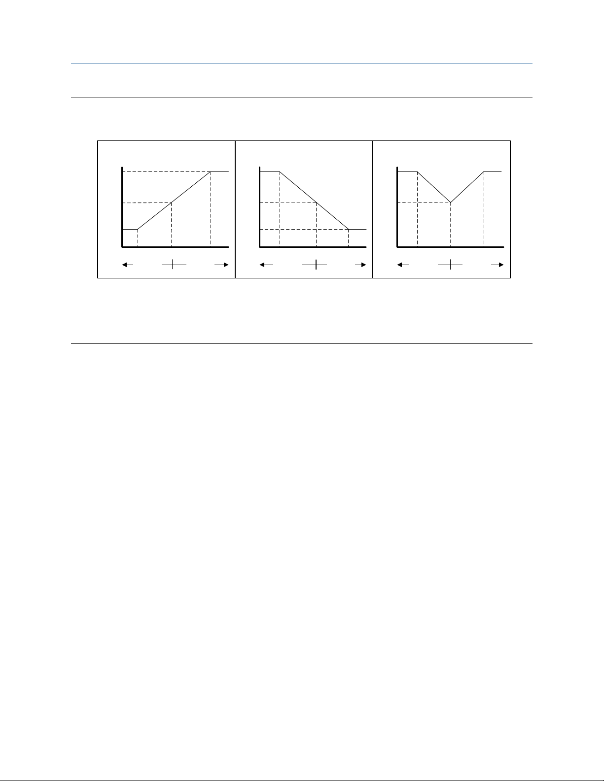
Effect of Flow Direction on mA Outputs
Flow Direction affects how the transmitter reports flow values via the mA Outputs. The mA Outputs are
affected by Flow Direction only if mA Output Process Variable is set to a flow variable.
Flow Direction and mA Outputs
The effect of Flow Direction on the mA Outputs depends on Lower Range Value configured for the mA
Output:
• If Lower Range Value is set to 0, see Figure 4-1.
• If Lower Range Value is set to a negative value, see Figure 4-2.
Figure 4-1: Effect of Flow Direction on the mA Output: Lower Range Value = 0
Flow Direction = Forward
20
12
mA output
4
-x 0 x
Reverse flow Forward flow
Flow Direction = Reverse, Negate Forward
20
12
mA output
4
-x 0 x
Reverse flow Forward flow
Flow Direction = Absolute Value, Bidirectional,
Negate Bidirectional
20
12
mA output
4
-x 0 x
Reverse flow Forward flow
• Lower Range Value = 0
• Upper Range Value = x
34 Micro Motion 1500 Transmitters with Analog Outputs
Configuration and Use Manual Configure process measurement
MMI-20019023 February 2022
Figure 4-2: Effect of Flow Direction on the mA Output: Lower Range Value < 0
Flow Direction = Forward
20
12
mA output
4
-x 0 x
Reverse flow Forward flow
Flow Direction = Reverse, Negate Forward
20
12
mA output
4
-x 0 x
Reverse flow Forward flow
• Lower Range Value = −x
• Upper Range Value = x
Flow Direction = Forward and Lower Range Value = 0
Configuration:
• Flow Direction = Forward
• Lower Range Value = 0 g/sec
Flow Direction = Absolute Value, Bidirectional,
Negate Bidirectional
20
12
mA output
4
-x 0 x
Reverse flow Forward flow
• Upper Range Value = 100 g/sec
Result:
• Under conditions of zero flow, the mA Output is 4 mA.
• Under conditions of forward flow, up to a flow rate of 100 g/sec, the mA Output varies between 4 mA and
20 mA in proportion to the flow rate.
• Under conditions of forward flow, if the flow rate equals or exceeds 100 g/sec, the mA Output will be
proportional to the flow rate up to 20.5 mA, and will be level at 20.5 mA at higher flow rates.
Flow Direction = Forward and Lower Range Value < 0
Configuration:
• Flow Direction = Forward
• Lower Range Value = −100 g/sec
• Upper Range Value = +100 g/sec
Result:
• Under conditions of zero flow, the mA Output is 12 mA.
• Under conditions of forward flow, for flow rates between 0 and +100 g/sec, the mA Output varies between
12 mA and 20 mA in proportion to (the absolute value of) the flow rate.
Configuration and Use Manual 35

Configure process measurement Configuration and Use Manual
February 2022 MMI-20019023
• Under conditions of forward flow, if (the absolute value of) the flow rate equals or exceeds 100 g/sec, the
mA Output is proportional to the flow rate up to 20.5 mA, and will be level at 20.5 mA at higher flow rates.
• Under conditions of reverse flow, for flow rates between 0 and −100 g/sec, the mA Output varies between
4 mA and 12 mA in inverse proportion to the absolute value of the flow rate.
• Under conditions of reverse flow, if the absolute value of the flow rate equals or exceeds 100 g/sec, the mA
Output is inversely proportional to the flow rate down to 3.8 mA, and will be level at 3.8 mA at higher
absolute values.
Flow Direction = Reverse
Configuration:
• Flow Direction = Reverse
• Lower Range Value = 0 g/sec
• Upper Range Value = 100 g/sec
Result:
• Under conditions of zero flow, the mA Output is 4 mA.
• Under conditions of reverse flow, for flow rates between 0 and +100 g/sec, the mA Output level varies
between 4 mA and 20 mA in proportion to the absolute value of the flow rate.
• Under conditions of reverse flow, if the absolute value of the flow rate equals or exceeds 100 g/sec, the mA
Output will be proportional to the absolute value of the flow rate up to 20.5 mA, and will be level at
20.5 mA at higher absolute values.
Effect of flow direction on Frequency Outputs
Flow direction affects how the transmitter reports flow values via the Frequency Outputs. The Frequency
Outputs are affected by flow direction only if Frequency Output Process Variable is set to a flow variable.
Table 4-1: Effect of the flow direction parameter and actual flow direction on Frequency Outputs
Actual flow direction
Flow Direction setting
Forward Hz > 0 0 Hz 0 Hz
Reverse 0 Hz 0 Hz Hz > 0
Bidirectional Hz > 0 0 Hz Hz > 0
Absolute Value Hz > 0 0 Hz Hz > 0
Negate Forward 0 Hz 0 Hz Hz > 0
Negate Bidirectional Hz > 0 0 Hz Hz > 0
Forward Zero flow Reverse
36 Micro Motion 1500 Transmitters with Analog Outputs

Configuration and Use Manual Configure process measurement
MMI-20019023 February 2022
Effect of flow direction on Discrete Outputs
The flow direction parameter affects the Discrete Output behavior only if Discrete Output Source is set to
Flow Direction.
Table 4-2: Effect of the flow direction parameter and actual flow direction on Discrete Outputs
Actual flow direction
Flow Direction setting
Forward OFF OFF ON
Reverse OFF OFF ON
Bidirectional OFF OFF ON
Absolute Value OFF OFF ON
Negate Forward ON OFF OFF
Negate Bidirectional ON OFF OFF
Forward Zero flow Reverse
Effect of flow direction on digital communications
Flow direction affects how flow values are reported via digital communications. The following table describes
the effect of the flow direction parameter and actual flow direction on flow values reported via digital
communications.
Table 4-3: Effect of the flow direction on flow values
Actual flow direction
Flow Direction setting
Forward Positive 0 Negative
Reverse Positive 0 Negative
Bidirectional Positive 0 Negative
Absolute Value Positive
Negate Forward Negative 0 Positive
Negate Bidirectional Negative 0 Positive
(1) Refer to the digital communications status bits for an indication of whether flow is positive or negative.
Forward Zero flow Reverse
(1)
0 Positive
(1)
Effect of flow direction on flow totals
Flow direction affects how flow totals and inventories are calculated.
Actual flow direction
Flow Direction setting
Forward Zero flow Reverse
Forward Totals increase Totals do not change Totals do not change
Reverse Totals do not change Totals do not change Totals increase
Bidirectional Totals increase Totals do not change Totals decrease
Absolute Value Totals increase Totals do not change Totals increase
Configuration and Use Manual 37

Configure process measurement Configuration and Use Manual
February 2022 MMI-20019023
Actual flow direction
Flow Direction setting
Negate Forward Totals do not change Totals do not change Totals increase
Negate Bidirectional Totals decrease Totals do not change Totals increase
Forward Zero flow Reverse
4.5 Configure density measurement
The density measurement parameters control how density is measured and reported.
4.5.1 Configure Density Measurement Unit
ProLink III Device Tools → Configuration → Process Measurement → Density
Field Communicator Configure → Manual Setup → Measurements → Density → Density Unit
Density Measurement Unit controls the measurement units that will be used in density calculations and
reporting.
Procedure
Set Density Measurement Unit to the option you want to use.
The default setting for Density Measurement Unit is g/cm3 (grams per cubic centimeter).
Options for Density Measurement Unit
The transmitter provides a standard set of measurement units for Density Measurement Unit. Different
communications tools may use different labels.
Label
Unit description
Specific gravity unit
Grams per cubic centimeter g/cm3 g/Cucm
Grams per liter g/l g/L
Grams per milliliter g/ml g/mL
Kilograms per liter kg/l kg/L
Kilograms per cubic meter kg/m3 kg/Cum
Pounds per U.S. gallon lbs/Usgal lb/gal
Pounds per cubic foot lbs/ft3 lb/Cuft
Pounds per cubic inch lbs/in3 lb/CuIn
Degrees API degAPI degAPI
Short ton per cubic yard sT/yd3 STon/Cuyd
(1) Non-standard calculation. This value represents line density divided by the density of water at 60 °F.
(1)
ProLink III Field Communicator
SGU SGU
38 Micro Motion 1500 Transmitters with Analog Outputs

Configuration and Use Manual Configure process measurement
MMI-20019023 February 2022
4.5.2 Configure two-phase flow parameters
ProLink III Device Tools → Configuration → Process Measurement → Density
Field Communicator • Configure → Manual Setup → Measurements → Density → Slug Low Limit
• Configure → Manual Setup → Measurements → Density → Slug High Limit
• Configure → Manual Setup → Measurements → Density → Slug Duration
The two-phase flow parameters control how the transmitter detects and reports two-phase flow (gas in a
liquid process or liquid in a gas process).
Note
Two-phase flow is also referred to as slug flow.
Procedure
1. Set Two-Phase Flow Low Limit to the lowest density value that is considered normal in your process.
Values below this will cause the transmitter to post Alert A105 (Two-Phase Flow).
Tip
Gas entrainment can cause your process density to drop temporarily. To reduce the occurrence of twophase flow alerts that are not significant to your process, set Two-Phase Flow Low Limit slightly below
your expected lowest process density.
You must enter Two-Phase Flow Low Limit in g/cm³, even if you configured another unit for density
measurement.
The default value for Two-Phase Flow Low Limit is 0.0 g/cm³. The range is 0.0 to 10.0 g/cm³.
2. Set Two-Phase Flow High Limit to the highest density value that is considered normal in your process.
Micro Motion recommends leaving Two-Phase Flow High Limit at the default value.
Values above this will cause the transmitter to post Alert A105 (Two-Phase Flow).
You must enter Two-Phase Flow High Limit in g/cm³, even if you configured another unit for density
measurement.
The default value for Two-Phase Flow High Limit is 5.0 g/cm³. The range is 0.0 to 10.0 g/cm³.
3. Set Two-Phase Flow Timeout to the number of seconds that the transmitter will wait for a two-phase
flow condition to clear before posting the alert.
The default value for Two-Phase Flow Timeout is 0.0 seconds, meaning that the alert will be posted
immediately. The range is 0.0 to 60.0 seconds.
The Two-Phase Flow alert is set immediately. The flow rate will hold the last measured value for the
Timeout time. Then the flow rate will report zero flow. If the density goes back in range, the error clears
immediately.
Configuration and Use Manual 39

Configure process measurement Configuration and Use Manual
February 2022 MMI-20019023
Detecting and reporting two-phase flow
Two-phase flow (gas in a liquid process or liquid in a gas process) can cause a variety of process control issues.
By configuring the two-phase flow parameters appropriately for your application, you can detect process
conditions that require correction.
Micro Motion recommends leaving Two-Phase Flow High Limit at the default value.
A two-phase flow condition occurs whenever the measured density goes below Two-Phase Flow Low Limit or
above Two-Phase Flow High Limit. If this occurs:
• A two-phase flow alert is posted to the active alert log.
• All outputs that are configured to represent flow rate hold their last pre-alert value for the number of
seconds configured in Two-Phase Flow Timeout.
If the two-phase flow condition clears before Two-Phase Flow Timeout expires:
• Outputs that represent flow rate revert to reporting actual flow.
• The two-phase flow alert is deactivated, but remains in the active alert log until it is acknowledged.
If the two-phase flow condition does not clear before Two-Phase Flow Timeout expires, the outputs that
represent flow rate report a flow rate of 0.
If Two-Phase Flow Timeout is set to 0.0 seconds, the outputs that represent flow rate will report a flow rate of
0 as soon as two-phase flow is detected.
4.5.3 Configure Density Damping
ProLink III
Field Communicator Configure → Manual Setup → Measurements → Density → Density Damping
Density Damping controls the amount of damping that will be applied to the line density value.
Damping is used to smooth out small, rapid fluctuations in process measurement. Damping Value specifies
the time period (in seconds) over which the transmitter will spread changes in the process variable. At the end
of the interval, the internal value will reflect 63% of the change in the actual measured value.
Tip
Density damping affects all process variables that are calculated from line density.
Procedure
Set Density Damping to the value you want to use.
The default value is 1.6 seconds. For most applications, the default density damping setting is sufficient. The
range depends on the core processor type and the setting of Update Rate, as shown in the following table:
Update Rate setting
Device Tools → Configuration → Process Measurement → Density
Damping range
Normal 0 to 51.2 seconds
Special 0 to 40.96 seconds
40 Micro Motion 1500 Transmitters with Analog Outputs

Configuration and Use Manual Configure process measurement
MMI-20019023 February 2022
Tip
• A high damping value makes the process variable appear smoother because the reported value changes
slowly.
• A low damping value makes the process variable appear more erratic because the reported value changes
more quickly.
• Whenever the damping value is non-zero, the reported measurement will lag the actual measurement
because the reported value is being averaged over time.
• In general, lower damping values are preferable because there is less chance of data loss, and less lag time
between the actual measurement and the reported value.
The value you enter is automatically rounded off to the nearest valid value. The valid values for Density
Damping depend on the setting of Update Rate.
Update Rate setting Valid damping values
Normal 0.0, 0.2, 0.4, 0.8, 1.6, 3.2, 6.4, 12.8, 25.6, 51.2
Special 0.0, 0.04, 0.08, 0.16, 0.32, 0.64, 1.28, 2.56, 5.12, 10.24,
20.48, 40.96
Effect of Density Damping on volume measurement
Density Damping affects liquid volume measurement. Liquid volume values are calculated from the damped
density value rather than the measured density value. Density Damping does not affect gas standard volume
measurement.
Interaction between Density Damping and Added Damping
When the mA Output is configured to report density, both Density Damping and Added Damping are
applied to the reported density value.
Density Damping controls the rate of change in the value of the process variable in transmitter memory.
Added Damping controls the rate of change reported via the mA Output.
If mA Output Process Variable is set to Density, and both Density Damping and Added Damping are set to
non-zero values, density damping is applied first, and the added damping calculation is applied to the result
of the first calculation. This value is reported over the mA Output.
4.5.4 Configure Density Cutoff
Density Cutoff specifies the lowest density value that will be reported as measured. All density values below
this cutoff will be reported as 0.
Procedure
Set Density Cutoff to the value you want to use.
For most applications, the default setting (0.2 g/cm³) is sufficient. The range is 0.0 g/cm³ to 0.5 g/cm³.
Configuration and Use Manual 41
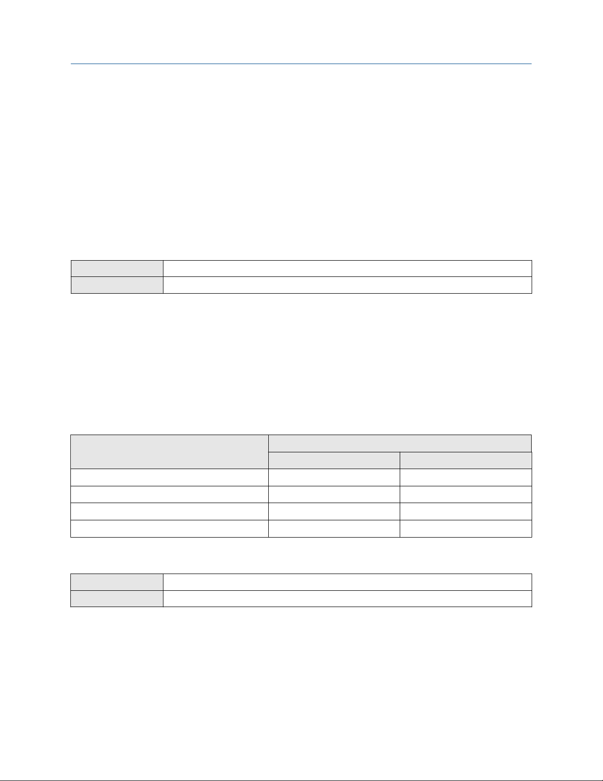
Configure process measurement Configuration and Use Manual
February 2022 MMI-20019023
Effect of Density Cutoff on volume measurement
Density Cutoff affects liquid volume measurement. If the density value goes below Density Cutoff, the
volume flow rate is reported as 0. Density Cutoff does not affect gas standard volume measurement. Gas
standard volume values are always calculated from the value configured for Standard Gas Density or polled
value if configured for polled base density.
4.6 Configure temperature measurement
The temperature measurement parameters control how temperature data from the sensor is reported.
4.6.1 Configure Temperature Measurement Unit
ProLink III Device Tools → Configuration → Process Measurement → Temperature
Field Communicator Configure → Manual Setup → Measurements → Temperature → Temperature Unit
Temperature Measurement Unit specifies the unit that will be used for temperature measurement.
Procedure
Set Temperature Measurement Unit to the option you want to use.
The default setting is Degrees Celsius.
Options for Temperature Measurement Unit
The transmitter provides a standard set of units for Temperature Measurement Unit. Different
communications tools may use different labels for the units.
Label
Unit description
Degrees Celsius °C degC
Degrees Fahrenheit °F degF
Degrees Rankine °R degR
Kelvin °K Kelvin
ProLink III Field Communicator
4.6.2 Configure Temperature Damping
ProLink III
Field Communicator Configure → Manual Setup → Measurements → Temperature → Temp Damping
Device Tools → Configuration → Temperature
Temperature Damping controls the amount of damping that will be applied to the line temperature value,
when the on-board temperature data is used (RTD).
Damping is used to smooth out small, rapid fluctuations in process measurement. Damping Value specifies
the time period (in seconds) over which the transmitter will spread changes in the process variable. At the end
of the interval, the internal value will reflect 63% of the change in the actual measured value.
42 Micro Motion 1500 Transmitters with Analog Outputs

Configuration and Use Manual Configure process measurement
MMI-20019023 February 2022
Tip
Temperature Damping affects all process variables, compensations, and corrections that use temperature
data from the sensor.
Procedure
Enter the value you want to use for Temperature Damping.
The default value is 4.8 seconds. For most applications, the default temperature damping setting is sufficient.
The range is 0.0 to 38.4 seconds.
Tip
• A high damping value makes the process variable appear smoother because the reported value changes
slowly.
• A low damping value makes the process variable appear more erratic because the reported value changes
more quickly.
• Whenever the damping value is non-zero, the reported measurement will lag the actual measurement
because the reported value is being averaged over time.
• In general, lower damping values are preferable because there is less chance of data loss, and less lag time
between the actual measurement and the reported value.
The value you enter is automatically rounded off to the nearest valid value. Valid values for Temperature
Damping are 0, 0.6, 1.2, 2.4, 4.8, 9.6, 19.2, and 38.4.
4.6.3 Effect of Temperature Damping on process measurement
Temperature Damping affects all processes and algorithms that use temperature data from the internal
sensor RTD.
Temperature compensation
Temperature compensation adjusts process measurement to compensate for the effect of temperature on
the sensor tubes.
4.7 Configure pressure compensation
Pressure compensation adjusts process measurement to compensate for the pressure effect on the sensor.
The pressure effect is the change in the sensor’s sensitivity to flow and density caused by the difference
between the calibration pressure and the process pressure.
Tip
Not all sensors or applications require pressure compensation. The pressure effect for a specific sensor model
can be found in the product data sheet located at . If you are uncertain about implementing pressure
compensation, contact customer service.
Prerequisites
You will need the flow factor, density factor, and calibration pressure values for your sensor.
• For the flow factor and density factor, see the product data sheet for your sensor.
• For the calibration pressure, see the calibration sheet for your sensor. If the data is unavailable, use 20 PSI.
Configuration and Use Manual 43

Configure process measurement Configuration and Use Manual
February 2022 MMI-20019023
4.7.1 Configure pressure compensation using ProLink III
Procedure
1. Choose Device Tools → Configuration → Process Measurement → Pressure Compensation.
2. Set Pressure Compensation Status to Enabled.
3. Set Pressure Unit to the appropriate unit.
If you will use an external pressure value, set Pressure Unit to match the pressure unit used by the
external pressure device.
4. Enter Flow Calibration Pressure for your sensor.
The calibration pressure is the pressure at which your sensor was calibrated, and defines the pressure at
which there is no pressure effect. If the data is unavailable, enter 20 PSI.
5. Enter Flow Factor for your sensor.
The flow factor is the percent change in the flow rate per PSI. When entering the value, reverse the
sign.
Example
If the flow factor is 0.000004 % per PSI, enter −0.000004 % per PSI.
6. Enter Density Factor for your sensor.
The density factor is the change in fluid density, in g/cm3/PSI. When entering the value, reverse the
sign.
Example
If the density factor is −0.000006 g/cm3/PSI, enter +0.000006 g/cm3/PSI.
7. Set Pressure Source to the method that the transmitter will use to obtain pressure data.
Option
Poll for external value The transmitter will poll an external pressure device, using HART
Fixed Value or Digital
Communications
Description
protocol over the primary mA Output.
The transmitter will use the pressure value that it reads from
memory.
• Fixed Value: The configured value is used.
• Digital Communications: A host writes transmitter data to
transmitter memory.
8. If you chose to poll for pressure data:
a) Select the Polling Slot to use.
b) Set Polling Control to Poll as Primary or Poll as Secondary, and click Apply.
Tip
• Poll as Primary: No other HART masters will be on the network.
44 Micro Motion 1500 Transmitters with Analog Outputs

Configuration and Use Manual Configure process measurement
MMI-20019023 February 2022
• Poll as Secondary: Other HART masters will be on the network. The Field Communicator is
not a HART master.
c) Set External Device Tag to the HART tag of the external pressure device, and click Apply.
d) Ensure that the primary mA Output is wired to support HART communications with the external
pressure device.
9. If you chose to use a fixed pressure value:
a) Set Fixed Value to the value to use, and click Apply
10. If you want to use digital communications, click Apply, then perform the necessary host programming
and communications setup to write pressure data to the transmitter at appropriate intervals.
Postrequisites
If you are using an external pressure value, verify the setup by checking the External Pressure value displayed
in the Inputs area of the main window.
4.7.2 Configure pressure compensation using the Field Communicator
Procedure
1. Choose Online → Configure → Manual Setup → Measurements → External Pressure/Temperature
→ Pressure.
2. Set Pressure Compensation to Enabled.
3. Enter Flow Cal Pressure for your sensor.
The calibration pressure is the pressure at which your sensor was calibrated, and defines the pressure at
which there is no pressure effect. If the data is unavailable, enter 20 PSI.
4. Enter Flow Press Factor for your sensor.
The flow factor is the percent change in the flow rate per PSI. When entering the value, reverse the
sign.
Example
If the flow factor is −0.0002 % per PSI, enter +0.0002 % per PSI.
5. Enter Dens Press Factor for your sensor.
The density factor is the change in fluid density, in g/cm3/PSI. When entering the value, reverse the
sign.
Example
If the density factor is −0.000006 g/cm3/PSI, enter +0.000006 g/cm3/PSI.
6. Determine how the transmitter will obtain pressure data, and perform the required setup.
Configuration and Use Manual 45

Configure process measurement Configuration and Use Manual
February 2022 MMI-20019023
Option Setup
A user-configured static
pressure value
a. Set Pressure Unit to the desired unit.
b. Set Compensation Pressure to the desired value.
Polling for pressure a. Ensure that the primary mA Output has been wired to support HART
polling.
b. Choose Online → Configure → Manual Setup → Measurements →
External Pressure/Temperature → External Polling.
c. Set Poll Control to Poll As Primary Host or Poll as Secondary Host.
d. Choose an unused polling slot.
e. Set External Tag to the HART tag of the external pressure device.
f. Set Polled Variable to Pressure.
Tip
• Poll as Primary: No other HART masters will be on the network.
• Poll as Secondary: Other HART masters will be on the network. The Field
Communicator is not a HART master.
A value written by
digital communications
a. Set Pressure Unit to the desired unit.
b. Perform the necessary host programming and communications setup
to write pressure data to the transmitter at appropriate intervals.
Postrequisites
If you are using an external pressure value, verify the setup by choosing Service Tools → Variables → External
Variables and checking the value displayed for External Pressure.
4.7.3 Options for Pressure Measurement Unit
The transmitter provides a standard set of measurement units for Pressure Measurement Unit. Different
communications tools may use different labels for the units. In most applications, Pressure Measurement
Unit should be set to match the pressure measurement unit used by the remote device.
Label
Unit description
Feet water @ 68 °F Ft Water @ 68°F ftH2O
Inches water @ 4 °C In Water @ 4°C inH2O @4DegC
Inches water @ 60 °F In Water @ 60°F inH2O @60DegF
Inches water @ 68 °F In Water @ 68°F inH2O
Millimeters water @ 4 °C mm Water @ 4°C mmH2O @4DegC
Millimeters water @ 68 °F mm Water @ 68°F mmH2O
ProLink III Field Communicator
46 Micro Motion 1500 Transmitters with Analog Outputs

Configuration and Use Manual Configure process measurement
MMI-20019023 February 2022
Label
Unit description
Millimeters mercury @ 0 °C mm Mercury @ 0°C mmHg
Inches mercury @ 0 °C In Mercury @ 0°C inHG
Pounds per square inch PSI psi
Bar bar bar
Millibar millibar mbar
Grams per square centimeter g/cm2 g/Sqcm
Kilograms per square centimeter kg/cm2 kg/Sqcm
Pascals pascals Pa
Kilopascals Kilopascals kPa
Megapascals Megapascals MPa
Torr @ 0 °C Torr @ 0°C torr
Atmospheres atms atms
ProLink III Field Communicator
Configuration and Use Manual 47

Configure process measurement Configuration and Use Manual
February 2022 MMI-20019023
48 Micro Motion 1500 Transmitters with Analog Outputs

Configuration and Use Manual Configure device options and preferences
MMI-20019023 February 2022
5 Configure device options and preferences
5.1 Configure response time parameters
You can configure the rate at which process data is polled and process variables are calculated.
5.1.1 Configure Update Rate
ProLink III Device Tools → Configuration → Process Measurement → Response → Update Rate
Field Communicator Configure → Manual Setup → Measurements → Update Rate
Update Rate controls the rate at which process data is polled and process variables are calculated. Update
Rate = Special produces faster and “noisier” response to changes in the process. Do not use Special mode
unless required by your application.
Prerequisites
Before setting Update Rate to Special:
• Check the effects of Special mode on specific process variables.
• Contact customer support.
Tip
For systems with a standard core processor, Special mode can improve performance for applications with
entrained air or Empty-Full-Empty conditions. This does not apply to systems with an enhanced core
processor.
Procedure
1. Set Update Rate as desired.
Option
Normal All process data is polled at the rate of 20 times per second (20 Hz).
Special A single, user-specified process variable is polled at the rate of 100 times per second
Description
All process variables are calculated at 20 Hz.
This option is appropriate for most applications.
(100 Hz). Other process data is polled at 6.25 Hz. Some process, diagnostic, and calibration
data is not polled.
All available process variables are calculated at 100 Hz.
Use this option only if required by your application.
If you change Update Rate, the settings for Flow Damping, and Density Damping are automatically
adjusted.
2. If you set Update Rate to Special, select the process variable to be polled at 100 Hz.
Configuration and Use Manual 49

Configure device options and preferences Configuration and Use Manual
February 2022 MMI-20019023
Effects of Update Rate = Special
Incompatible features and functions
Special mode is not compatible with the following features and functions:
• Enhanced events. Use basic events instead.
• All calibration procedures.
• Zero verification.
• Restoring the factory zero or the prior zero.
If required, you can switch to Normal mode, perform the desired procedures, and then return to Special
mode.
Process variable updates
Some process variables are not updated when Special mode is enabled.
Table 5-1: Special mode and process variable updates
Always polled and updated Updated only when the petroleum
measurement application is
disabled
• Mass flow
• Volume flow
• Gas standard volume flow
• Density
• Temperature
• Drive gain
• LPO amplitude
• Status [contains Event 1 and Event
2 (basic events)]
• Mass total
• Volume total
• Live zero
• Gas standard volume total
• RPO amplitude
• Core input voltage
• Mass inventory
• Volume inventory
• Gas standard volume inventory
5.1.2 Configure Response Time
Never updated
All other process variables and
calibration data. They retain the values
held at the time you enabled Special
mode.
ProLink III
Field Communicator Not available
Device Tools → Configuration → Process Measurement → Response → Response Time
Response Time is used to apply a different algorithm to the calculation of process variables from the raw
process data.
Restriction
Response Time is available only on systems with the enhanced core processor.
50 Micro Motion 1500 Transmitters with Analog Outputs

Configuration and Use Manual Configure device options and preferences
MMI-20019023 February 2022
Procedure
Set Response Time as desired.
Option Description
Normal (Legacy) Transmitter calculates process variables at the standard speed. This option is
selected if this parameter was configured on an earlier version of ProLink III
software.
Special (Legacy) Transmitter calculates process variables at a faster speed. This option is
selected if this parameter was configured on an earlier version of ProLink III
software.
Normal - Optimal Filtering Transmitter calculates process variables at standard filtering and speed.
Low Filtering - Fastest
Response
High Filtering - Smoothest
Output
Service For factory use only.
Transmitter calculates process variables at the fastest speed.
Transmitter calculates process variables at the smoothest (least noisy)
response to changes in the process.
5.2 Configure alert handling
The alert handling parameters control the transmitter’s response to process and device conditions.
5.2.1 Configure Fault Timeout
ProLink III
Field Communicator Configure → Alert Setup → Alert Severity → Fault Timeout
Fault Timeout controls the delay before fault actions are performed.
Restriction
Fault Timeout is applied only to the following alerts (listed by Status Alert Code): A003, A004, A005, A008,
A016, A017, A033. For all other alerts, fault actions are performed as soon as the alert is detected.
Device Tools → Configuration → Fault Processing
Procedure
Set Fault Timeout as desired.
The default value is 0 seconds. The range is 0 to 60 seconds.
If you set Fault Timeout to 0, fault actions are performed as soon as the alert condition is detected.
The fault timeout period begins when the transmitter detects an alert condition. During the fault timeout
period, the transmitter continues to report its last valid measurements.
If the fault timeout period expires while the alert is still active, the fault actions are performed. If the alert
condition clears before the fault timeout expires, no fault actions are performed.
Configuration and Use Manual 51

Configure device options and preferences Configuration and Use Manual
February 2022 MMI-20019023
5.2.2 Configure Status Alert Severity
ProLink III Device Tools → Configuration → Alert Severity
Field Communicator Configure → Alert Setup → Alert Severity → Set Alert Severity
Use Status Alert Severity to control the fault actions that the transmitter performs when it detects an alert
condition.
Restriction
• For some alerts, Status Alert Severity is not configurable.
• For some alerts, Status Alert Severity can be set only to two of the three options.
Tip
Use the default settings for Status Alert Severity unless you have a specific requirement to change them.
Procedure
1. Select a status alert.
2. For the selected status alert, set Status Alert Severity as desired.
Option Description
Fault Actions when fault is detected:
• The alert is posted to the Alert List.
• Outputs go to the configured fault action (after Fault Timeout has expired, if
applicable).
• Digital communications go to the configured fault action (after Fault Timeout has
expired, if applicable).
• The status LED (if available) changes to red or yellow (depending on alert severity).
Actions when alert clears:
• Outputs return to normal behavior.
• Digital communications return to normal behavior.
• The status LED (if available) returns to green and may or may not flash.
Informational Actions when fault is detected:
• The alert is posted to the Alert List.
• The status LED (if available) changes to red or yellow (depending on alert severity).
Actions when alert clears:
• The status LED (if available) returns to green and may or may not flash.
Ignore No action
52 Micro Motion 1500 Transmitters with Analog Outputs

Configuration and Use Manual Configure device options and preferences
MMI-20019023 February 2022
Status alerts and options for Status Alert Severity
Table 5-2: Status alerts and Status Alert Severity
Alert code Status message Default severity Notes Configurable?
A001 EEPROM Error Fault No
A002 RAM Error Fault No
A003 No Sensor Response Fault Yes
A004 Temperature Overrange Fault No
A005 Mass Flow Rate Overrange Fault Yes
A006 Characterization Required Fault Yes
A008 Density Overrange Fault Yes
A009 Transmitter Initializing/
Warming Up
A010 Calibration Failure Fault No
A011 Zero Calibration Failed:
Low
A012 Zero Calibration Failed:
High
A013 Zero Calibration Failed:
Unstable
A014 Transmitter Failure Fault No
A016 Sensor RTD Failure Fault Yes
A017 T-Series RTD Failure Fault Yes
A018 EEPROM Error
(Transmitter)
A019 RAM Error (Transmitter) Fault No
A020 No Flow Cal Value Fault Yes
A021 Incorrect Sensor Type (K1) Fault No
A022 Configuration Database
Corrupt (Core Processor)
A023 Internal Totals Corrupt
(Core Processor)
Fault Yes
Fault Yes
Fault Yes
Fault Yes
Fault No
Fault Applies only to flowmeters with the
standard core processor.
Fault Applies only to flowmeters with the
standard core processor.
No
No
A024 Program Corrupt (Core
Processor)
A025 Boot Sector Fault (Core
Processor)
A026 Sensor/Transmitter
Communications Failure
A028 Core Processor Write
Failure
Configuration and Use Manual 53
Fault Applies only to flowmeters with the
standard core processor.
Fault Applies only to flowmeters with the
standard core processor.
Fault No
Fault No
No
No

Configure device options and preferences Configuration and Use Manual
February 2022 MMI-20019023
Table 5-2: Status alerts and Status Alert Severity (continued)
Alert code Status message Default severity Notes Configurable?
A031 Low Power Fault Applies only to flowmeters with the
enhanced core processor.
A032 Meter Verification in
Progress: Outputs to Fault
A033 Insufficient Right/Left
Pickoff Signal
A034 Meter Verification Failed Fault Applies only to transmitters with
A035 Meter Verification Aborted Fault Applies only to transmitters with
A100 mA Output 1 Saturated Informational Can be set to either Informational
A101 mA Output 1 Fixed Informational Can be set to either Informational
A102 Drive Overrange Informational Yes
A104 Calibration in Progress Informational Can be set to either Informational
Varies Applies only to transmitters with
Smart Meter Verification.
If outputs are set to Last Measured
Value, severity is Info. If outputs are
set to Fault, severity is Fault.
Fault Applies only to flowmeters with the
enhanced core processor.
Smart Meter Verification.
Smart Meter Verification.
or Ignore, but cannot be set to
Fault.
or Ignore, but cannot be set to
Fault.
or Ignore, but cannot be set to
Fault.
No
No
Yes
Yes
Yes
Yes
Yes
Yes
A105 Slug Flow Informational Yes
A106 Burst Mode Enabled Informational Can be set to either Informational
or Ignore, but cannot be set to
Fault.
A107 Power Reset Occurred Informational Normal transmitter behavior;
occurs after every power cycle.
A108 Basic Event 1 On Informational Applies only to basic events. Yes
A109 Basic Event 2 On Informational Applies only to basic events. Yes
A110 Frequency Output
Saturated
A111 Frequency Output Fixed Informational Can be set to either Informational
A112 Upgrade Transmitter
Software
A113 mA Output 2 Saturated Informational Can be set to either Informational
Informational Can be set to either Informational
or Ignore, but cannot be set to
Fault.
or Ignore, but cannot be set to
Fault.
Informational Applies only to systems with
transmitter software earlier than
v5.0.
or Ignore, but cannot be set to
Fault.
Yes
Yes
Yes
Yes
Yes
Yes
54 Micro Motion 1500 Transmitters with Analog Outputs

Configuration and Use Manual Configure device options and preferences
MMI-20019023 February 2022
Table 5-2: Status alerts and Status Alert Severity (continued)
Alert code Status message Default severity Notes Configurable?
A114 mA Output 2 Fixed Informational Can be set to either Informational
or Ignore, but cannot be set to
Fault.
A115 No External Input or Polled
Data
A118 Discrete Output 1 Fixed Informational Can be set to either Informational
A119 Discrete Output 2 Fixed Informational Can be set to either Informational
A131 Meter Verification in
Progress: Outputs to Last
Measured Value
A132 Sensor Simulation Active Informational Applies only to flowmeters with the
A141 DDC trigger(s) have
completed
Informational Yes
or Ignore, but cannot be set to
Fault.
or Ignore, but cannot be set to
Fault.
Informational Applies only to transmitters with
Smart Meter Verification.
enhanced core processor.
Can be set to either Informational
or Ignore, but cannot be set to
Fault.
Informational Applies only to flowmeters with the
enhanced core processor.
Can be set to either Informational
or Ignore, but cannot be set to
Fault.
Yes
Yes
Yes
Yes
To Informational
or Ignore only
Yes
5.3 Configure informational parameters
The informational parameters can be used to identify or describe your meter. They are not used in process
measurement and they are not required.
5.3.1 Configure Sensor Serial Number
ProLink III
Field Communicator Configure → Manual Setup → Info Parameters → Sensor Information → Sensor Serial Number
Sensor Serial Number lets you store the serial number of the sensor component of your flowmeter in
transmitter memory. This parameter is not used in processing and is not required.
Procedure
1. Obtain the sensor serial number from your sensor tag.
2. Enter the serial number in the Sensor Serial Number field.
Configuration and Use Manual 55
Device Tools → Configuration → Informational Parameters → Sensor

Configure device options and preferences Configuration and Use Manual
February 2022 MMI-20019023
5.3.2 Configure Sensor Material
ProLink III Device Tools → Configuration → Informational Parameters → Sensor
Field Communicator Configure → Manual Setup → Info Parameters → Sensor Information → Tube Wetted Material
Sensor Material lets you store the type of material used for your sensor’s wetted parts in transmitter
memory. This parameter is not used in processing and is not required.
Procedure
1. Obtain the material used for your sensor’s wetted parts from the documents shipped with your sensor,
or from a code in the sensor model number.
To interpret the model number, refer to the product data sheet for your sensor.
2. Set Sensor Material to the appropriate option.
5.3.3 Configure Sensor Liner Material
ProLink III Device Tools → Configuration → Informational Parameters → Sensor
Field Communicator Configure → Manual Setup → Info Parameters → Sensor Information → Tube Lining
Sensor Liner Material lets you store the type of material used for your sensor liner in transmitter memory.
This parameter is not used in processing and is not required.
Procedure
1. Obtain your sensor’s liner material from the documents shipped with your sensor, or from a code in the
sensor model number.
To interpret the model number, refer to the product data sheet for your sensor.
2. Set Sensor Liner Material to the appropriate option.
5.3.4 Configure Sensor Flange Type
ProLink III
Field Communicator Configure → Manual Setup → Info Parameters → Sensor Information → Sensor Flange
Sensor Flange Type lets you store your sensor’s flange type in transmitter memory. This parameter is not
used in processing and is not required.
Procedure
1. Obtain your sensor’s flange type from the documents shipped with your sensor, or from a code in the
sensor model number.
To interpret the model number, refer to the product data sheet for your sensor.
Device Tools → Configuration → Informational Parameters → Sensor
2. Set Sensor Flange Type to the appropriate option.
56 Micro Motion 1500 Transmitters with Analog Outputs

Configuration and Use Manual Configure device options and preferences
MMI-20019023 February 2022
5.3.5 Configure Descriptor
ProLink III Device Tools → Configuration → Informational Parameters → Transmitter
Field Communicator Configure → Manual Setup → Info Parameters → Transmitter Info → Descriptor
Descriptor lets you store a description in transmitter memory. The description is not used in processing and is
not required.
Procedure
Enter a description for the transmitter or device
You can use up to 16 characters for the description.
5.3.6 Configure Message
ProLink III Device Tools → Configuration → Informational Parameters → Transmitter
Field Communicator Configure → Manual Setup → Info Parameters → Transmitter Info → Message
Message lets you store a short message in transmitter memory. This parameter is not used in processing and
is not required.
Procedure
Enter a short message for the transmitter or device.
Your message can be up to 32 characters long.
5.3.7 Configure Date
ProLink III
Field Communicator Configure → Manual Setup → Info Parameters → Transmitter Info → Date
Date lets you store a static date (not updated by the transmitter) in transmitter memory. This parameter is
not used in processing and is not required.
Procedure
Enter the date you want to use, in the form mm/dd/yyyy.
Tip
ProLink III provides a calendar tool to help you select the date.
Device Tools → Configuration → Informational Parameters → Transmitter
Configuration and Use Manual 57

Configure device options and preferences Configuration and Use Manual
February 2022 MMI-20019023
58 Micro Motion 1500 Transmitters with Analog Outputs

Configuration and Use Manual Integrate the meter with the control system
MMI-20019023 February 2022
6 Integrate the meter with the control system
6.1 Configure the transmitter channels
ProLink III Device Tools → Configuration → I/O → Outputs
Field communicator Configure → Manual Setup → Inputs/Outputs → Channels → Channel C
You can configure Channel C on your transmitter to operate as a Frequency Output or a Discrete Output. The
channel configuration must match the wiring at the transmitter terminals.
Prerequisites
To avoid causing process errors:
• Configure the channels before configuring the outputs.
• Before changing the channel configuration, ensure that all control loops affected by the channel are under
manual control.
Procedure
Set Channel C as desired.
Option
Frequency Output Channel C will operate as a Frequency Output.
Discrete Output Channel C will operate as a Discrete Output.
Postrequisites
For each channel that you configured, perform or verify the corresponding input or output configuration.
When the configuration of a channel is changed, the channel’s behavior will be controlled by the
configuration that is stored for the selected input or output type, and the stored configuration may not be
appropriate for your process.
After verifying channel and output configuration, return the control loop to automatic control.
Description
6.2 Configure the mA Output
The mA Output is used to report the configured process variable. The mA Output parameters control how the
process variable is reported.
Your transmitter has one mA Output: Channel A.
Restriction
The process variable assigned to the primary mA Output is automatically assigned to the Frequency Output.
You cannot assign a different process variable.
Configuration and Use Manual 59
Integrate the meter with the control system Configuration and Use Manual
February 2022 MMI-20019023
Important
Whenever you change an mA Output parameter, verify all other mA Output parameters before returning the
meter to service. In some situations, the transmitter automatically loads a set of stored values, and these
values may not be appropriate for your application.
6.2.1 Configure mA Output Process Variable
ProLink III Device Tools → Configuration → I/O → Outputs → mA Output
Field Communicator Configure → Manual Setup → Inputs/Outputs → mA Output → Primary Variable
Use mA Output Process Variable to select the variable that is reported over the mA Output. This variable is
applied automatically to the Frequency Output.
Prerequisites
• If you plan to configure the output to report volume flow, ensure that you have set Volume Flow Type as
desired: Liquid or Gas Standard Volume.
• If you are using the HART variables, be aware that changing the configuration of mA Output Process
Variable will change the configuration of the HART Primary Variable (PV) and the HART Tertiary Variable
(TV).
Procedure
Set mA Output Process Variable as desired.
The default setting is Mass Flow Rate.
Postrequisites
If you changed the setting of mA Output Process Variable, verify the settings of Lower Range Value (LRV)
and Upper Range Value (URV).
Options for mA Output Process Variable
The transmitter provides a basic set of options for mA Output Process Variable, plus several applicationspecific options. Different communications tools may use different labels for the options.
Table 6-1: Standard mA Output process variables
Process variable Label
ProLink III Field Communicator
Gas standard volume flow rate Gas Standard Volume Flow Rate Gas vol flo
Mass flow rate Mass Flow Rate Mass flo
Volume flow rate Volume Flow Rate Vol flo
Table 6-2: PVR mA Output process variables
Process variable Label
ProLink III Field Communicator
Uncorrected oil flow Oil Flow Rate At Line Oil Flow Rate at Line
60 Micro Motion 1500 Transmitters with Analog Outputs
Configuration and Use Manual Integrate the meter with the control system
MMI-20019023 February 2022
Table 6-2: PVR mA Output process variables (continued)
Process variable Label
ProLink III Field Communicator
Uncorrected water cut Water Cut At Line Water Cut at Line
Uuncorrected water flow Water Flow Rate At Line Water Flow Rate at Line
Corrected oil flow Oil Flow Rate At Reference Oil Flow Rate at Reference
Corrected water cut Water Cut At Reference Water Cut at Reference
Corrected water flow Water Flow Rate At Reference Water Flow Rate at Reference
Shrinkage factor corrected net oil at
line
Shrinkage factor corrected net oil at
60F
Shrinkage factor corrected volume of
mix at 60F
SF Oil Flow Rate At Line Shrinkage Factor Oil Flow Rate at Line
SF Oil Flow Rate At Reference Shrinkage Factor Oil Flow Rate at
Reference
SF Volume Flow Rate At Reference Shrinkage Factor Volume Flow Rate at
Reference
6.2.2 Configure Lower Range Value (LRV) and Upper Range Value
(URV)
ProLink III
Field Communicator • Configure → Manual Setup → Inputs/Outputs → mA Output → mA Output Settings → LRV
The Lower Range Value (LRV) and Upper Range Value (URV) are used to scale the mA Output, that is, to
define the relationship between mA Output Process Variable and the mA Output level.
Prerequisites
Ensure that mA Output Process Variable is set to the desired process variable. Each process variable has its
own set of LRV and URV values. When you change the values of LRV and URV, you are configuring values for
the currently assigned mA Output process variable.
Device Tools → Configuration → I/O → Outputs → mA Output
• Configure → Manual Setup → Inputs/Outputs → mA Output → mA Output Settings → URV
Ensure that the measurement unit for the configured process variable has been set as desired.
Procedure
Set LRV and URV as desired.
• LRVis the value of mA Output Process Variable represented by an output of 4 mA. The default value for
LRV depends on the setting of mA Output Process Variable. Enter LRV in the measurement units that are
configured for mA Output Process Variable.
• URV is the value of mA Output Process Variable represented by an output of 20 mA. The default value for
URV depends on the setting of mA Output Process Variable. Enter URV in the measurement units that are
configured for mA Output Process Variable.
Configuration and Use Manual 61

Integrate the meter with the control system Configuration and Use Manual
February 2022 MMI-20019023
The mA Output uses a range of 4–20 mA to represent mA Output Process Variable. Between LRV and URV,
the mA Output is linear with the process variable. If the process variable drops below LRV or rises above URV,
the transmitter posts an output saturation alert.
Default values for Lower Range Value (LRV) and Upper Range Value (URV)
Each option for mA Output Process Variable has its own LRV and URV. If you change the configuration of mA
Output Process Variable, the corresponding LRV and URV are loaded and used.
Table 6-3: Default values for Lower Range Value (LRV) and Upper Range Value (URV)
Process variable LRV URV
All mass flow variables –200.000 g/sec 200.000 g/sec
All liquid volume flow variables –0.200 l/sec 0.200 l/sec
Gas standard volume flow –423.78 SCFM 423.78 SCFM
6.2.3 Configure AO Cutoff
ProLink III Device Tools → Configuration → I/O → Outputs → mA Output
Field Communicator Configure → Manual Setup → Inputs/Outputs → mA Output → mA Output Settings → PV MAO Cutoff
AO Cutoff (Analog Output Cutoff) specifies the lowest mass flow rate, volume flow rate, or gas standard
volume flow rate that will be reported through the mA Output. Any flow rates below AO Cutoff will be
reported as 0.
Restriction
AO Cutoff is applied only if mA Output Process Variable is set to Mass Flow Rate, Volume Flow Rate, or Gas
Standard Volume Flow Rate. If mA Output Process Variable is set to a different process variable, AO Cutoff is
not configurable, and the transmitter does not implement the AO cutoff function.
Procedure
Set AO Cutoff as desired.
The default value for AO Cutoff is 0.0 g/sec.
Tip
For most applications, the default value of AO Cutoff should be used. Contact customer service before
changing AO Cutoff.
Interaction between AO Cutoff and process variable cutoffs
When mA Output Process Variable is set to a flow variable (for example, mass flow rate or volume flow rate),
AO Cutoff interacts with Mass Flow Cutoff or Volume Flow Cutoff. The transmitter puts the cutoff into effect
at the highest flow rate at which a cutoff is applicable.
Example: Cutoff interaction
Configuration:
• mA Output Process Variable = Mass Flow Rate
62 Micro Motion 1500 Transmitters with Analog Outputs

Configuration and Use Manual Integrate the meter with the control system
MMI-20019023 February 2022
• Frequency Output Process Variable = Mass Flow Rate
• AO Cutoff = 10 g/sec
• Mass Flow Cutoff = 15 g/sec
Result: If the mass flow rate drops below 15 g/sec, all outputs representing mass flow will report zero flow.
Example: Cutoff interaction
Configuration:
• mA Output Process Variable = Mass Flow Rate
• Frequency Output Process Variable = Mass Flow Rate
• AO Cutoff = 15 g/sec
• Mass Flow Cutoff = 10 g/sec
Result:
• If the mass flow rate drops below 15 g/sec but not below 10 g/sec:
— The mA Output will report zero flow.
— The Frequency Output will report the actual flow rate.
• If the mass flow rate drops below 10 g/sec, both outputs will report zero flow.
6.2.4 Configure Added Damping
ProLink III
Field Communicator Configure → Manual Setup → Inputs/Outputs → mA Output → mA Output Settings → PV Added
Added Damping controls the amount of damping that will be applied to the mA Output.
Damping is used to smooth out small, rapid fluctuations in process measurement. Damping Value specifies
the time period (in seconds) over which the transmitter will spread changes in the process variable. At the end
of the interval, the internal value will reflect 63% of the change in the actual measured value.
Added Damping affects the reporting of mA Output Process Variable through the mA Output only. It does
not affect the reporting of that process variable via any other method (e.g., a Frequency Output or digital
communications), or the value of the process variable used in calculations.
Note
Added Damping is not applied if the mA Output is fixed (for example, during loop testing) or if the mA
Output is reporting a fault. Added Damping is applied while sensor simulation is active.
Procedure
Device Tools → Configuration → I/O → Outputs → mA Output
Damping
Set Added Damping to the desired value.
The default value is 0.0 seconds. The range is 0.0 to 440 seconds.
When you specify a value for Added Damping, the transmitter automatically rounds the value down to the
nearest valid value.
Configuration and Use Manual 63

Integrate the meter with the control system Configuration and Use Manual
February 2022 MMI-20019023
Note
Added Damping values are affected by the setting of Update Rate and 100 Hz Variable.
Table 6-4: Valid values for Added Damping
Update rate
Setting of Update Rate
Normal N/A 20 Hz 0.0, 0.1, 0.3, 0.75, 1.6, 3.3, 6.5, 13.5, 27.5,
Process variable
in effect
Valid values for Added Damping
55, 110, 220, 440
Special 100 Hz variable (if assigned
to the mA Output)
100 Hz variable (if not
assigned to the mA Output)
All other process variables
100 Hz 0.0, 0.04, 0.12, 0.30, 0.64, 1.32, 2.6, 5.4,
11, 22, 44, 88, 176, 350
6.25 Hz 0.0, 0.32, 0.96, 2.40, 5.12, 10.56, 20.8,
43.2, 88, 176, 352
Interaction between mA Output Damping and process variable damping
When mA Output Source is set to a flow rate variable, mA Output Damping interacts with Flow Damping. If
multiple damping parameters are applicable, the effect of damping the process variable is calculated first,
and the mA output damping calculation is applied to the result of that calculation.
Example: Damping interaction
Configuration:
• Flow Damping = 1 second
• mA Output Source = Mass Flow Rate
• mA Output Damping = 2 seconds
Result: A change in the mass flow rate will be reflected in the mA Output over a time period that is greater
than 3 seconds. The exact time period is calculated by the transmitter according to internal algorithms which
are not configurable.
6.2.5 Configure mA Output Fault Action and mA Output Fault Level
ProLink III
Field Communicator Configure → Manual Setup → Inputs/Outputs → mA Output → mA Fault Settings
mA Output Fault Action controls the behavior of the mA Output if the transmitter encounters an internal
fault condition.
Note
For some faults only: If Fault Timeout is set to a non-zero value, the transmitter will not implement the fault
action until the timeout has elapsed.
Procedure
1. Set mA Output Fault Action to the desired value.
The default setting is Downscale.
64 Micro Motion 1500 Transmitters with Analog Outputs
Device Tools → Configuration → Fault Processing

Configuration and Use Manual Integrate the meter with the control system
MMI-20019023 February 2022
Restriction
If Digital Communications Fault Action is set to NAN (not a number), you cannot set mA Output Fault
Action or Frequency Output Fault Action to None. If you try to do this, the transmitter will not accept
the configuration.
2. If you set mA Output Fault Action to Upscale or Downscale, set mA Output Fault Level as desired.
Postrequisites
NOTICE
If you set mA Output Fault Action or Frequency Output Fault Action to None, be sure to set Digital
Communications Fault Action to None. If you do not, the output will not report actual process data, and this
may result in measurement errors or unintended consequences for your process.
Options for mA Output Fault Action and mA Output Fault Level
Option mA Output behavior
Upscale Goes to the configured fault level Default: 22.0 mA
Downscale (default) Goes to the configured fault level Default: 2.0 mA
Internal Zero Goes to the mA Output level associated with a
process variable value of 0 (zero), as determined
by Lower Range Value and Upper Range Value
settings
None Tracks data for the assigned process variable; no
fault action
mA Output Fault Level
Range: 21.0 to 24.0 mA
Range: 1.0 to 3.6 mA
Not applicable
Not applicable
6.3 Configure the Frequency Output
The Frequency Output is used to report a process variable. The Frequency Output parameters control how the
process variable is reported. Your transmitter has one Frequency Output: Channel C.
Restriction
The process variable assigned to the primary mA Output is automatically assigned to the Frequency Output.
You cannot assign a different process variable.
Important
Whenever you change a Frequency Output parameter, verify all other Frequency Output parameters before
returning the flowmeter to service. In some situations, the transmitter automatically loads a set of stored
values, and these values may not be appropriate for your application.
6.3.1 Configure Frequency Output Polarity
ProLink III
Field Communicator Configure → Manual Setup → Inputs/Outputs → Frequency Output → FO Settings → FO Polarity
Configuration and Use Manual 65
Device Tools → Configuration → I/O → Outputs → Frequency Output

Integrate the meter with the control system Configuration and Use Manual
February 2022 MMI-20019023
Frequency Output Polarity controls how the output indicates the ON (active) state. The default value, Active
High, is appropriate for most applications. Your receiving device might require an Active Low setting.
Procedure
Set Frequency Output Polarity as desired.
The default setting is Active High.
Options for Frequency Output Polarity
Polarity option Reference voltage (OFF) Pulse voltage (ON)
Active High 0 As determined by power supply,
pull-up resistor, and load. See
the installation manual for your
transmitter.
Active Low As determined by power supply,
pull-up resistor, and load. See
the installation manual for your
transmitter.
0
6.3.2 Configure Frequency Output Scaling Method
ProLink III Device Tools → Configuration → I/O → Outputs → Frequency Output
Field Communicator Configure → Manual Setup → Inputs/Outputs → Frequency Output → FO Scaling
Frequency Output Scaling Method defines the relationship between output pulse and flow units. Set
Frequency Output Scaling Method as required by your frequency receiving device.
Procedure
1. Set Frequency Output Scaling Method.
Option
Frequency=Flow (default) Frequency calculated from flow rate
Pulses/Unit A user-specified number of pulses represents one flow unit
Units/Pulse A pulse represents a user-specified number of flow units
Description
2. Set additional required parameters.
• If you set Frequency Output Scaling Method to Frequency=Flow, set Rate Factor and Frequency
Factor.
• If you set Frequency Output Scaling Method to Pulses/Unit, define the number of pulses that will
represent one flow unit.
• If you set Frequency Output Scaling Method to Units/Pulse, define the number of units that each
pulse will indicate.
For all scaling methods, the transmitter puts out a fixed number of pulses per unit, and at the same
time, the Frequency Output signal varies in proportion to flowrate.
66 Micro Motion 1500 Transmitters with Analog Outputs

Configuration and Use Manual Integrate the meter with the control system
MMI-20019023 February 2022
Calculate frequency from flow rate
The Frequency=Flow option is used to customize the Frequency Output for your application when you do not
know appropriate values for Units/Pulse or Pulses/Unit.
If you specify Frequency=Flow, you must provide values for Rate Factor and Frequency Factor:
Rate Factor
Frequency Factor
The resulting Frequency Factor must be within the range of the Frequency Output 0 to 10,000 Hz:
• If Frequency Factor is less than 1 Hz, reconfigure the receiving device for a higher pulses/unit setting.
• If Frequency Factor is greater than 10,000 Hz, reconfigure the receiving device for a lower pulses/unit
setting.
The maximum flow rate that you want the Frequency Output to report.
A value calculated as follows:
FrequencyFactor
where:
T
Factor to convert selected time base to seconds
N
Number of pulses per flow unit, as configured in the receiving device
RateFactor
T
× N
6.3.3 Configure Frequency Output Fault Action and Frequency
Output Fault Level
ProLink III
Field Communicator • Configure → Manual Setup → Inputs/Outputs → Frequency Output → FO Fault Parameters → FO
Device Tools → Configuration → Fault Processing
Fault Action
• Configure → Manual Setup → Inputs/Outputs → Frequency Output → FO Fault Parameters → FO
Fault Level
Frequency Output Fault Action controls the behavior of the Frequency Output if the transmitter encounters
an internal fault condition.
Note
For some faults only: If Fault Timeout is set to a non-zero value, the transmitter will not implement the fault
action until the timeout has elapsed.
Procedure
1. Set Frequency Output Fault Action as desired.
The default value is Downscale (0 Hz).
2. If you set Frequency Output Fault Action to Upscale, set Frequency Fault Level to the desired value.
The default value is 15000 Hz. The range is 10 to 15000 Hz.
Configuration and Use Manual 67
Integrate the meter with the control system Configuration and Use Manual
February 2022 MMI-20019023
Options for Frequency Output Fault Action
Table 6-5: Options for Frequency Output Fault Action
Label Frequency Output behavior
Upscale Goes to configured Upscale value:
• Range: 10 Hz to 15000 Hz
• Default: 15000 Hz
Downscale 0 Hz
Internal Zero 0 Hz
None (default) Tracks data for the assigned process variable; no fault action
NOTICE
If you set mA Output Fault Action or Frequency Output Fault Action to None, be sure to set Digital
Communications Fault Action to None. If you do not, the output will not report actual process data, and this
may result in measurement errors or unintended consequences for your process.
Restriction
If Digital Communications Fault Action is set to NAN (not a number), you cannot set mA Output Fault
Action or Frequency Output Fault Action to None. If you try to do this, the transmitter will not accept the
configuration.
6.4 Configure the Discrete Output
The Discrete Output is used to report specific meter or process conditions. The Discrete Output parameters
control which condition is reported and how it is reported.
Restriction
Before you can configure the Discrete Output, you must configure a channel to operate as a Discrete Output.
Important
Whenever you change a Discrete Output parameter, verify all other Discrete Output parameters before
returning the meter to service. In some situations, the transmitter automatically loads a set of stored values,
and these values may not be appropriate for your application.
6.4.1 Configure Discrete Output Source
ProLink III
Field Communicator Configure → Manual Setup → Inputs/Outputs → Discrete Output → DO Assignment
Device Tools → Configuration → I/O → Outputs → Discrete Output
Discrete Output Source controls which device condition or process condition is reported via the Discrete
Output.
Procedure
Set Discrete Output Source to the desired option.
The default setting for Discrete Output Source is Flow Direction.
68 Micro Motion 1500 Transmitters with Analog Outputs

Configuration and Use Manual Integrate the meter with the control system
MMI-20019023 February 2022
Options for Discrete Output Source
Option Label State Discrete Output
ProLink III Field Communicator
Discrete Event 1–5
Event 1–2
Flow Switch Flow Switch Indicator Flow Switch ON Site-specific
(2)
(1)
Enhanced Event 1
Enhanced Event 2
Enhanced Event 3
Enhanced Event 4
Enhanced Event 5
Event 1
Event 2
Event 1 or Event 2
Status
Discrete Event x ON Site-specific
OFF 0 V
Event 1
Event 2
Event 1 or Event 2
ON Site-specific
OFF 0 V
OFF 0 V
voltage
Flow Direction Forward Reverse
Indicator
Calibration in Progress Calibration in Progress Calibration in Progress ON Site-specific
Fault Fault Indication Fault ON Site-specific
(1) Events configured using the enhanced event model.
(2) Events configured using the basic event model.
Forward/Reverse Forward flow 0 V
Reverse flow Site-specific
OFF 0 V
OFF 0 V
Important
If you assign Flow Switch to the Discrete Output, you should also configure Flow Switch Variable, Flow
Switch Setpoint, and Hysteresis.
Related information
Configure an enhanced event
Fault indication with a Discrete Output
Configure Flow Switch parameters
ProLink III
Field Communicator • Configure → Manual Setup → Inputs/Outputs → Discrete Output → Flow Switch Source
Device Tools → Configuration → I/O → Outputs → Discrete Output
• Configure → Manual Setup → Inputs/Outputs → Discrete Output → Flow Switch Setpoint
• Configure → Manual Setup → Inputs/Outputs → Discrete Output → Hysteresis
Configuration and Use Manual 69

Integrate the meter with the control system Configuration and Use Manual
February 2022 MMI-20019023
Flow Switch is used to indicate that the flow rate (measured by the configured flow variable) has moved past
the configured setpoint, in either direction. The flow switch is implemented with a user-configurable
hysteresis.
Procedure
1. Set Discrete Output Source to Flow Switch, if you have not already done so.
2. Set Flow Switch Variable to the flow variable that you want to use to control the flow switch.
3. Set Flow Switch Setpoint to the value at which the flow switch will be triggered (after Hysteresis is
applied).
• If the flow rate is below this value, the Discrete Output is ON.
• If the flow rate is above this value, the Discrete Output is OFF.
4. Set Hysteresis to the percentage of variation above and below the setpoint that will operate as a
deadband.
Hysteresis defines a range around the setpoint within which the flow switch will not change. The
default is 5%. The valid range is 0.1% to 10%.
Example
If Flow Switch Setpoint = 100 g/sec and Hysteresis = 5%, and the first measured flow rate is above
100 g/sec, the Discrete Output is OFF. It will remain OFF unless the flow rate drops below 95 g/sec. If
this happens, the Discrete Output will turn ON, and remain ON until the flow rate rises above
105 g/sec. At this point it turns OFF and will remain OFF until the flow rate drops below 95 g/sec.
6.4.2 Configure Discrete Output Polarity
ProLink III
Field Communicator Configure → Manual Setup → Inputs/Outputs → Discrete Output → DO Polarity
Discrete Outputs have two states: ON (active) and OFF (inactive). Two different voltage levels are used to
represent these states. Discrete Output Polarity controls which voltage level represents which state.
Procedure
Set Discrete Output Polarity as desired.
The default setting is Active High.
Options for Discrete Output Polarity
Polarity option
Active High • When asserted (condition tied to DO is
Device Tools → Configuration → I/O → Outputs → Discrete Output
Description
true), the circuit provides a pull-up to 24 V.
• When not asserted (condition tied to DO is
false), the circuit provides 0 V.
70 Micro Motion 1500 Transmitters with Analog Outputs
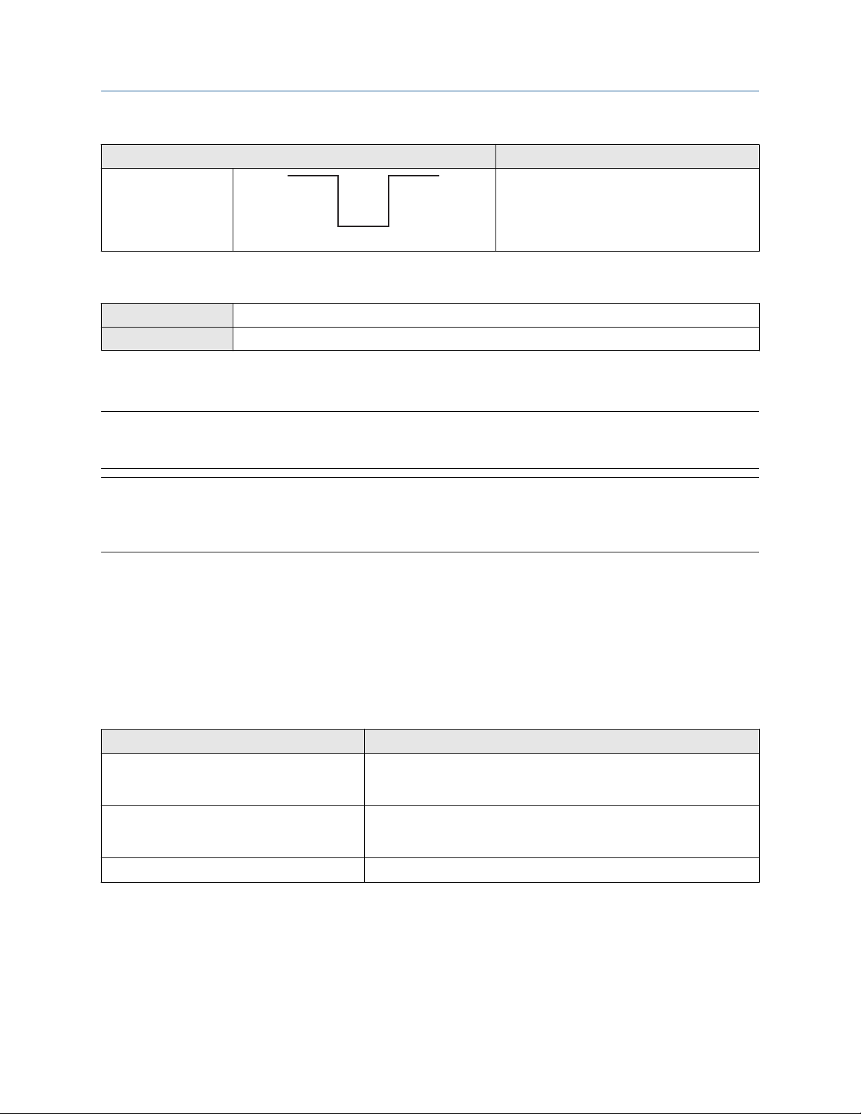
Configuration and Use Manual Integrate the meter with the control system
MMI-20019023 February 2022
Polarity option Description
Active Low • When asserted (condition tied to DO is
true), the circuit provides 0 V.
• When not asserted (condition tied to DO is
false), the circuit provides a pull-up to 24 V.
6.4.3 Configure Discrete Output Fault Action
ProLink III Device Tools → Configuration → Fault Processing
Field Communicator Configure → Manual Setup → Inputs/Outputs → Discrete Output → DO Fault Action
Discrete Output Fault Action controls the behavior of the Discrete Output if the transmitter encounters an
internal fault condition.
Note
For some faults only: If Fault Timeout is set to a non-zero value, the transmitter will not implement the fault
action until the timeout has elapsed.
NOTICE
Do not use Discrete Output Fault Action as a fault indicator. If you do, you may not be able to distinguish a
fault condition from a normal operating condition. If you want to use the Discrete Output as a fault indicator,
set Discrete Output Source to Fault and set Discrete Output Fault Action to None.
Procedure
Set Discrete Output Fault Action as desired.
The default setting is None.
Related information
Fault indication with a Discrete Output
Options for Discrete Output Fault Action
Label
Upscale • Fault: Discrete Output is ON (site-specific voltage)
• No fault: Discrete Output is controlled by its assignment
Downscale • Fault: Discrete Output is OFF (0 V)
• No fault: Discrete Output is controlled by its assignment
None (default) Discrete Output is controlled by its assignment
Discrete Output behavior
Configuration and Use Manual 71

Integrate the meter with the control system Configuration and Use Manual
February 2022 MMI-20019023
Fault indication with a Discrete Output
To indicate faults via a Discrete Output, set Discrete Output Source to Fault. Then, if a fault occurs, the
Discrete Output is always ON and the setting of Discrete Output Fault Action is ignored.
6.5 Configure events
An event occurs when the real-time value of a user-specified process variable moves past a user-defined
setpoint. Events are used to provide notification of process changes or to perform specific transmitter actions
if a process change occurs.
Your transmitter supports two event models:
• Basic event model
• Enhanced event model
6.5.1 Configure a basic event
ProLink III Device Tools → Configuration → Events → Basic Events
Field Communicator Not available
A basic event is used to provide notification of process changes. A basic event occurs (is ON) if the real-time
value of a user-specified process variable moves above (HI) or below (LO) a user-defined setpoint. You can
define up to two basic events. Event status can be queried via digital communications, and a Discrete Output
can be configured to report event status.
Procedure
1. Select the event that you want to configure.
2. Specify Event Type.
Option
HI x > A
LO x < A
3. Assign a process variable to the event.
4. Set a value for Setpoint A.
5. Optional: Configure a Discrete Output to switch states in response to the event status.
Description
The event occurs when the value of the assigned process variable (x) is greater
than the setpoint (Setpoint A), endpoint not included.
The event occurs when the value of the assigned process variable (x) is less than
the setpoint (Setpoint A), endpoint not included.
6.5.2 Configure an enhanced event
ProLink III
Field Communicator Configure → Alert Setup → Discrete Events
72 Micro Motion 1500 Transmitters with Analog Outputs
Device Tools → Configuration → Events → Enhanced Events

Configuration and Use Manual Integrate the meter with the control system
MMI-20019023 February 2022
An enhanced event is used to provide notification of process changes and, optionally, to perform specific
transmitter actions if the event occurs. An enhanced event occurs (is ON) if the real-time value of a userspecified process variable moves above (HI) or below (LO) a user-defined setpoint, or in range (IN) or out of
range (OUT) with respect to two user-defined setpoints. You can define up to five enhanced events.
Procedure
1. Select the event that you want to configure.
2. Specify Event Type.
Option Description
HI x > A
The event occurs when the value of the assigned process variable (x) is greater
than the setpoint (Setpoint A), endpoint not included.
LO x < A
The event occurs when the value of the assigned process variable (x) is less than
the setpoint (Setpoint A), endpoint not included.
IN A ≤ x ≤ B
The event occurs when the value of the assigned process variable (x) is in range,
that is, between Setpoint A and Setpoint B, endpoints included.
OUT x ≤ A or x ≥ B
The event occurs when the value of the assigned process variable (x) is out of
range, that is, less than Setpoint A or greater than Setpoint B, endpoints
included.
3. Assign a process variable to the event.
4. Set values for the required setpoints.
• For HI and LO events, set Setpoint A.
• For IN and OUT events, set Setpoint A and Setpoint B.
5. Optional: Configure a Discrete Output to switch states in response to the event status.
6. Optional: Specify the action or actions that the transmitter will perform when the event occurs.
• With ProLink III: Device Tools → Configuration → I/O → Action Assignment
• With a field communicator: Configure → Alert Setup → Discrete Events → Assign Discrete Action
Options for Enhanced Event Action
Action
ProLink III Field Communicator
Standard
Label
None (default) None None
Start sensor zero Start Sensor Zero Perform auto zero
Start/stop all totalizers Start/Stop All Totalization Start/stop totals
Configuration and Use Manual 73

Integrate the meter with the control system Configuration and Use Manual
February 2022 MMI-20019023
Action Label
ProLink III Field Communicator
Reset mass total Reset Mass Total Reset mass total
Reset volume total Reset Volume Total Reset volume total
Reset gas standard volume total Reset Gas Std Volume Total Reset gas standard volume total
Reset all totals Reset All Totals Reset totals
Meter verification
Start meter verification test Start Meter Verification Not available
Note
Before assigning actions to an enhanced event, check the status of the event. If it is ON, all assigned actions
will be performed when the new configuration is implemented. If this is not acceptable, wait until an
appropriate time to assign actions to the event.
6.6 Configure digital communications
The digital communications parameters control how the transmitter will communicate using digital
communications.
Your transmitter supports the following types of digital communications:
• HART/Bell 202 over the primary mA terminals
• Modbus/RS-485 over the RS-485 terminals
• Modbus RTU via the service port
The 1500 has only a single Modbus port.
Procedure
You have the following digital communication options:
• During the first 10 seconds after a power cycle, connect to the service port using address 111 and the
service port communication parameters.
• After the initial startup period, you can connect using Modbus with the configured Modbus address and
communication parameters.
6.6.1 Configure HART/Bell 202 communications
HART/Bell 202 communications parameters support HART communications with the transmitter's primary
mA terminals over a HART/Bell 202 network.
Configure basic HART parameters
ProLink III
Field Communicator Configure → Manual Setup → Inputs/Outputs →
74 Micro Motion 1500 Transmitters with Analog Outputs
Device Tools → Configuration → Communications →
Communications (HART)
Communications

Configuration and Use Manual Integrate the meter with the control system
MMI-20019023 February 2022
Basic HART parameters include the HART address, HART tags, and the operation of the primary mA Output.
HART/Bell 202 communications parameters support HART communication with the transmitter's primary mA
terminals over a HART/Bell 202 network. The HART/Bell 202 communications parameters include:
• HART Address (Polling Address)
• mA Output Action
• Burst Parameters (optional)
• HART Variables (optional)
Procedure
1. Set HART Address to a value that is unique on your network.
• Default: 0
• Range: 0 to 15
Tip
• The default address is typically used unless you are in a multidrop environment.
• Devices using HART protocol to communicate with the transmitter may use either HART Address or
HART Tag (Software Tag) to identify the transmitter. Configure either or both, as required by your
other HART devices.
2. Ensure that mA Output Action is configured appropriately.
Option
Description
Enabled (Live) The primary mA Output reports process data as configured.
Disabled (Fixed) The primary mA Output is fixed at 4 mA and does not report process data.
Important
If you use ProLink III to set HART Address to 0, the program automatically enables mA Output Action.
If you use ProLink III to set HART Address to any other value, the program automatically disables mA
Output Action. This is designed to make it easier to configure the transmitter for legacy behavior.
Always verify mA Output Action after setting HART Address.
Configure burst parameters
ProLink III
Field Communicator Configure → Manual Setup → Inputs/Outputs → Communications → Set Up Burst Mode
Burst mode is a mode of communication during which the transmitter regularly broadcasts HART digital
information over the mA Output. The burst parameters control the information that is broadcast when burst
mode is enabled.
Tip
In typical installations, burst mode is disabled. Enable burst mode only if you are using a HART Triloop.
Device Tools → Configuration → Communications → Communications (HART)
Configuration and Use Manual 75
Integrate the meter with the control system Configuration and Use Manual
February 2022 MMI-20019023
Procedure
1. Enable Burst Mode.
2. Set Burst Mode Output as desired.
Label Description
ProLink III Field Communicator
Source (Primary Variable) PV The transmitter sends the primary variable (PV) in the
configured measurement units in each burst (e.g.,
14.0 g/sec, 13.5 g/sec, 12.0 g/sec.
Primary Variable (Percent
Range/Current)
Process Variables/Current Process variables/current The transmitter sends PV, SV, TV, and QV values in
Transmitter variables Fld dev var The transmitter sends four user-specified process variables
% range/current The transmitter sends the PV’s percent of range and the
PV’s actual mA level in each burst (e.g., 25%, 11.0 mA.
measurement units and the PV’s actual milliamp reading in
each burst (e.g., 50 g/sec, 23 °C, 50 g/sec, 0.0023 g/cm3,
11.8 mA.
in each burst.
3. Ensure that the burst output variables are set appropriately.
• If you set Burst Mode Output to send four user-specified variables, set the four process variables to
be sent in each burst.
• If you set Burst Mode Output to any other option, ensure that the HART variables are set as desired.
Configure HART variables (PV, SV, TV, QV)
ProLink III
Field Communicator Configure → Manual Setup → Inputs/Outputs → Variable Mapping
The HART variables are a set of four variables predefined for HART use. The HART variables include the
Primary Variable (PV), Secondary Variable (SV), Tertiary Variable (TV), and Quaternary Variable (QV). You can
assign specific process variables to the HART variables, and then use standard HART methods to read or
broadcast the assigned process data.
Device Tools → Configuration → Communications → Communications (HART)
Restriction
The TV is automatically set to match the PV and cannot be configured independently.
Tip
The Tertiary Variable and Quaternary Variable are also called the Third Variable (TV) and Fourth Variable (FV).
Options for HART variables
Table 6-6: Standard HART process variables
Process variable Primary
Variable (PV)
Gas Standard Volume Flow Rate ✓ ✓ ✓ ✓
76 Micro Motion 1500 Transmitters with Analog Outputs
Secondary
Variable (SV)
Third Variable
(TV)
Fourth
Variable (QV )
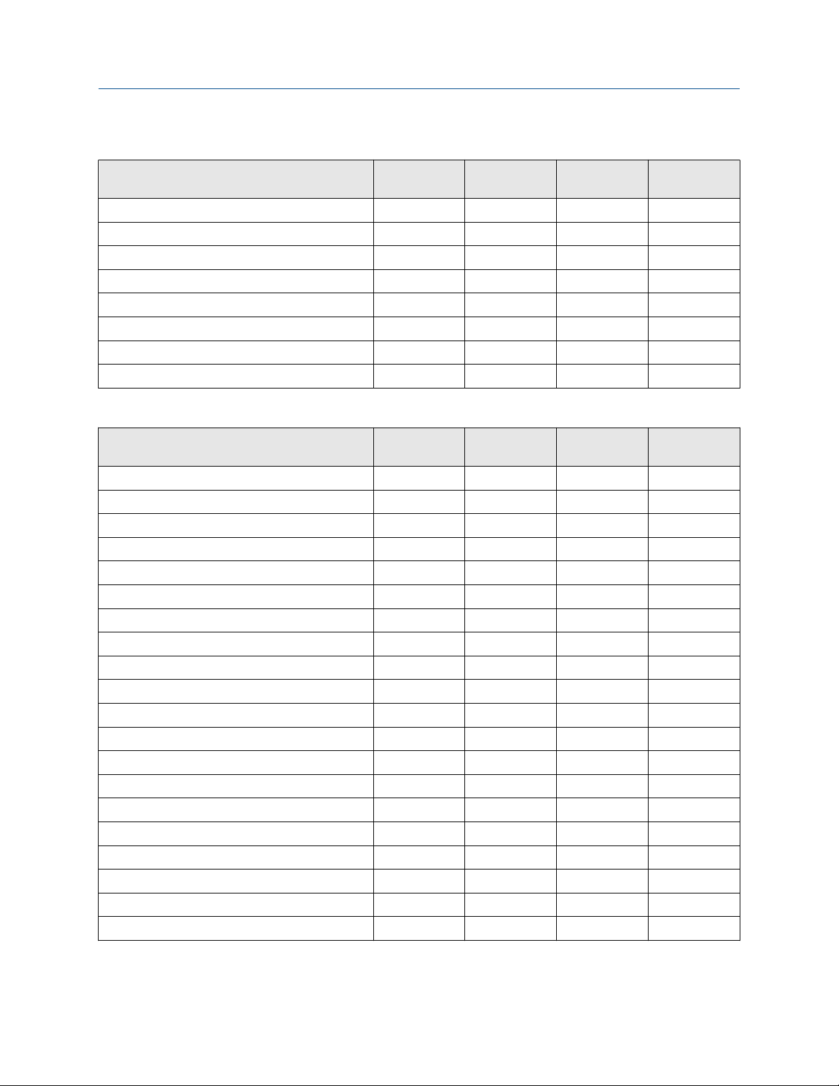
Configuration and Use Manual Integrate the meter with the control system
MMI-20019023 February 2022
Table 6-6: Standard HART process variables (continued)
Process variable Primary
Variable (PV)
Gas Standard Volume Inventory ✓
Gas Standard Volume Total ✓
Line (Gross) Volume Flow Rate ✓ ✓ ✓ ✓
Line (Gross) Volume Inventory ✓
Line (Gross) Volume Total ✓
Mass Flow Rate ✓ ✓ ✓ ✓
Mass Inventory ✓
Mass Total ✓
Secondary
Variable (SV)
Third Variable
(TV)
Table 6-7: PVR-only HART process variables
Process variable Primary
Variable (PV)
Corrected Oil Flow ✓ ✓ ✓
Corrected Oil Total ✓
Corrected Water Cut ✓
Corrected Water Flow ✓ ✓ ✓
Secondary
Variable (SV)
Third Variable
(TV)
Fourth
Variable (QV )
Fourth
Variable (QV )
Corrected Water Total ✓
Density of Oil @ Line Fixd degAPI ✓
Density of Oil @ Line Fixd SGU ✓
Oil Total @ Line ✓
Shrinkage Factor Corrected Oil Flow @ 60F ✓ ✓ ✓
Shrinkage Factor Corrected Oil Flow @ Line ✓ ✓ ✓
Shrinkage Factor Corrected Oil Total @ 60F ✓
Shrinkage Factor Corrected Oil Total @ Line ✓
Shrinkage Factor Corrected Total of Mix @ 60F ✓
Shrinkage Factor Corrected Volume Of Mix @ 60F ✓ ✓ ✓
Uncorrected Oil Flow ✓ ✓ ✓
Uncorrected Water Cut ✓
Uncorrected Water Flow ✓ ✓ ✓
Volume Flow of Mix at Line ✓ ✓ ✓
Volume Total Of Mix @ Line ✓
Water Total @ Line ✓
Configuration and Use Manual 77

Integrate the meter with the control system Configuration and Use Manual
February 2022 MMI-20019023
Table 6-8: TMR-only HART process variables
Process variable Primary
Variable (PV)
Remediated Mass Flow ✓ ✓ ✓
Remediated Mass Total ✓
Remediated Mass Inventory ✓
Secondary
Variable (SV)
Third Variable
(TV)
Fourth
Variable (QV )
Table 6-9: PVR- and TBR-only HART process variables
Process variable Primary
Variable (PV)
Unremediated Density ✓
Secondary
Variable (SV)
Third Variable
(TV)
Fourth
Variable (QV )
Table 6-10: PVR, TBR, and TMR HART process variables
Process variable Primary
Variable (PV)
Total Remediated Time ✓
Secondary
Variable (SV)
Third Variable
(TV)
Fourth
Variable (QV )
Interaction of HART variables and transmitter outputs
The HART variables are automatically reported through specific transmitter outputs. They may also be
reported through HART burst mode, if enabled on your transmitter.
Table 6-11: HART variables and transmitter outputs
HART variable Reported via Comments
Primary Variable (PV) Primary mA output If one assignment is changed, the other is changed
automatically, and vice versa.
Secondary Variable (SV) Not associated with an
output
Tertiary Variable (TV) Frequency Output If one assignment is changed, the other is changed
Quaternary Variable (QV) Not associated with an
output
The SV must be configured directly, and the value of the SV
is available only via digital communications.
automatically, and vice versa.
The QV must be configured directly, and the value of the
QV is available only via digital communications.
6.6.2 Configure Modbus/RS-485 communications
ProLink III
Field Communicator Configure → Manual Setup → Inputs/Outputs → Communications → Set Up RS-485 Port
Modbus/RS-485 communications parameters control Modbus communication with the transmitter's RS-485
terminals.
Procedure
1. Set Disable Modbus ASCII as desired.
Device Tools → Configuration → Communications → RS-485 Terminals
78 Micro Motion 1500 Transmitters with Analog Outputs

Configuration and Use Manual Integrate the meter with the control system
MMI-20019023 February 2022
Support for Modbus ASCII limits the set of addresses that are available for the transmitter's Modbus
address.
Modbus ASCII support Available Modbus addresses
Disabled 1–127, excluding 111 (111 is reserved to the service port)
Enabled 1–15, 32–47, 64–79, and 96–110
2. Set Protocol to match the protocol used by your Modbus/RS-485 host.
Option Description
Modbus RTU (default) 8–bit communications
Modbus ASCII 7–bit communications
If support for Modbus ASCII is disabled, you must use Modbus RTU.
3. Set Modbus Address to a unique value on the network.
4. Set Parity, Stop Bits, and Baud Rate as appropriate for your network.
5. Set Floating-Point Byte Order to match the byte order used by your Modbus host.
Code Byte order
0 1–2 3–4
1 3–4 1–2
2 2–1 4–3
3 4–3 2–1
See the following table for the bit structure of bytes 1 through 4.
Table 6-12: Bit structure of floating-point bytes
Byte Bits Definition
1 SEEEEEEE S=Sign
E=Exponent
2 EMMMMMMM E=Exponent
M=Mantissa
3 MMMMMMMM M=Mantissa
4 MMMMMMMM M=Mantissa
6. (Optional) Set Additional Communications Response Delay in delay units.
A delay unit is 2/3 of the time required to transmit one character, as calculated for the port currently in
use and the character transmission parameters. Valid values range from 1 to 255.
Additional Communications Response Delay is used to synchronize Modbus communications with
hosts that operate at a slower speed than the transmitter. The value specified here will be added to
each response the transmitter sends to the host.
Configuration and Use Manual 79

Integrate the meter with the control system Configuration and Use Manual
February 2022 MMI-20019023
Tip
Do not set Additional Communications Response Delay unless required by your Modbus host.
6.6.3 Configure Digital Communications Fault Action
ProLink III Device Tools → Configuration → Fault Processing
Field Communicator Configure → Alert Setup → I/O Fault Actions → Comm Fault Action
Digital Communications Fault Action specifies the values that will be reported via digital communications if
the device encounters an internal fault condition.
Procedure
Set Digital Communications Fault Action as desired.
The default setting is None.
Restriction
• If mA Output Fault Action or Frequency Output Fault Action is set to None, Digital Communications
Fault Action should also be set to None. If you do not, the output will not report actual process data, and
this may result in measurement errors or unintended consequences for your process.
• If you set Digital Communications Fault Action to NAN, you cannot set mA Output Fault Action or
Frequency Output Fault Action to None. If you try to do this, the transmitter will not accept the
configuration.
Options for Digital Communications Fault Action
Label
ProLink III Field Communicator
Upscale Upscale • Process variable values indicate that the value is greater
Downscale Downscale • Process variable values indicate that the value is lower
Zero IntZero-All 0 • Flow rate variables go to the value that represents a
Description
than the upper sensor limit.
• Totalizers stop incrementing.
than the lower sensor limit.
• Totalizers stop incrementing.
flow rate of 0 (zero).
• Density is reported as 0.
• Temperature is reported as 0 °C , or the equivalent if
other units are used (e.g., 32 °F .
• Drive gain is reported as measured.
• Totalizers stop incrementing.
80 Micro Motion 1500 Transmitters with Analog Outputs

Configuration and Use Manual Integrate the meter with the control system
MMI-20019023 February 2022
Label Description
ProLink III Field Communicator
Not a Number Not-a-Number • Process variables are reported as IEEE NAN.
• Drive gain is reported as measured.
• Modbus scaled integers are reported as Max Int.
• Totalizers stop incrementing.
Flow to Zero IntZero-Flow 0 • Flow rates are reported as 0.
• Other process variables are reported as measured.
• Totalizers stop incrementing.
None None (default) • All process variables are reported as measured.
• Totalizers increment if they are running.
NOTICE
If you set mA Output Fault Action or Frequency Output Fault Action to None, be sure to set Digital
Communications Fault Action to None. If you do not, the output will not report actual process data, and this
may result in measurement errors or unintended consequences for your process.
Restriction
If Digital Communications Fault Action is set to NAN (not a number), you cannot set mA Output Fault
Action or Frequency Output Fault Action to None. If you try to do this, the transmitter will not accept the
configuration.
Configuration and Use Manual 81

Integrate the meter with the control system Configuration and Use Manual
February 2022 MMI-20019023
82 Micro Motion 1500 Transmitters with Analog Outputs

Configuration and Use Manual Complete the configuration
MMI-20019023 February 2022
7 Complete the configuration
7.1 Test or tune the system using sensor simulation
Use sensor simulation to test the system's response to a variety of process conditions, including boundary
conditions, problem conditions, or alert conditions, or to tune the loop.
Prerequisites
Before enabling sensor simulation, ensure that your process can tolerate the effects of the simulated process
values.
Restriction
Sensor simulation is available only on flow meters with the enhanced core processor.
Procedure
1. Navigate to the sensor simulation menu.
Communications tool Menu path
ProLink III Device Tools → Diagnostics → Testing → Sensor Simulation
Field Communicator Service Tools → Simulate → Simulate Sensor
2. Enable sensor simulation.
3. For mass flow, set Wave Form as desired and enter the required values.
Option
Fixed Fixed Value
Sawtooth Period
Sine Period
4. For density, set Wave Form as desired and enter the required values.
Option
Required values
Minimum
Maximum
Minimum
Maximum
Required values
Fixed Fixed Value
Sawtooth Period
Minimum
Maximum
Sine Period
Configuration and Use Manual 83

Complete the configuration Configuration and Use Manual
February 2022 MMI-20019023
Option Required values
Minimum
Maximum
5. For temperature, set Wave Form as desired and enter the required values.
Option Required values
Fixed Fixed Value
Sawtooth Period
Minimum
Maximum
Sine Period
Minimum
Maximum
6. Observe the system response to the simulated values and make any appropriate changes to the
transmitter configuration or to the system.
7. Modify the simulated values and repeat.
8. When you have finished testing or tuning, disable sensor simulation.
7.1.1 Sensor simulation
Sensor simulation allows you to test the system or tune the loop without having to create the test conditions
in your process. When sensor simulation is enabled, the transmitter reports the simulated values for mass
flow, density, and temperature, and takes all appropriate actions. For example, the transmitter might apply a
cutoff, activate an event, or post an alert.
When sensor simulation is enabled, the simulated values are stored in the same memory locations used for
process data from the sensor. The simulated values are then used throughout transmitter functioning. For
example, sensor simulation will affect:
• All mass flow rate, temperature, and density values displayed or reported via outputs or digital
communications
• The mass total and mass inventory values
• All volume calculations and data, including reported values, volume totals, and volume inventories
• All mass, temperature, density, or volume values logged to Data Logger
Sensor simulation does not affect any diagnostic values.
Unlike actual mass flow rate and density values, the simulated values are not temperature-compensated
(adjusted for the effect of temperature on the sensor’s flow tubes).
84 Micro Motion 1500 Transmitters with Analog Outputs

Configuration and Use Manual Complete the configuration
MMI-20019023 February 2022
7.2 Back up transmitter configuration
ProLink III provides a configuration upload/download function which allows you to save configuration sets to
your PC. This allows you to back up and restore your transmitter configuration. This is also a convenient way
to replicate a configuration across multiple devices.
Restriction
This function is not available with any other communications tools.
Procedure
To back up the transmitter configuration using ProLink III:
a) Choose Device Tools → Configuration Transfer → Save or Load Configuration Data.
b) In the Configuration group box, select the configuration data you want to save.
c) Click Save, then specify a file name and location on your computer.
d) Click Start Save.
The backup file is saved to the specified name and location. It is saved as a text file and can be read using any
text editor.
7.3 Enable write-protection on the transmitter
configuration
ProLink III
Field Communicator Configure → Manual Setup → Info Parameters → Transmitter Info → Write Protect
If the transmitter is write-protected, the configuration is locked and nobody can change it until it is unlocked.
This prevents accidental or unauthorized changes to the transmitter configuration parameters.
Device Tools → Configuration → Write-Protection
Configuration and Use Manual 85

Complete the configuration Configuration and Use Manual
February 2022 MMI-20019023
86 Micro Motion 1500 Transmitters with Analog Outputs

Configuration and Use Manual Operations, maintenance, and troubleshooting
MMI-20019023 February 2022
Part III
Operations, maintenance, and
troubleshooting
Configuration and Use Manual 87

Operations, maintenance, and troubleshooting Configuration and Use Manual
February 2022 MMI-20019023
88 Micro Motion 1500 Transmitters with Analog Outputs

Configuration and Use Manual Transmitter operation
MMI-20019023 February 2022
8 Transmitter operation
8.1 Record the process variables
Micro Motion suggests that you make a record of specific process variable measurements, including the
acceptable range of measurements, under normal operating conditions. This data will help you recognize
when the process or diagnostic variables are unusually high or low, and may help you diagnose and
troubleshoot application issues.
Procedure
Record the following process and diagnostic variables, under normal operating conditions.
Measurement
Variable
Flow rate
Density
Temperature
Tube frequency
Pickoff voltage
Drive gain
Typical average Typical high Typical low
8.2 View process variables
ProLink III
Field Communicator Overview → Shortcuts → Variables → Process Variables
Process variables provide information about the state of the process fluid, such as flow rate, density, and
temperature, as well as running totals. Process variables can also provide data about flowmeter operation,
such as drive gain and pickoff voltage. This information can be used to understand and troubleshoot your
process.
8.2.1 View process variables and other data using ProLink III
View the desired variable on the main screen under Process Variables. See View process variables and other
data using ProLink III for more information.
Monitor process variables, diagnostic variables, and other data to maintain process quality.
ProLink III automatically displays process variables, diagnostic variables, and other data on the main screen.
Tip
ProLink III allows you to choose the process variables that appear on the main screen. You can also choose
whether to view data in Analog Gauge view or digital view, and you can customize the gauge settings. For
more information, see the .
Configuration and Use Manual 89

Transmitter operation Configuration and Use Manual
February 2022 MMI-20019023
8.2.2 View process variables using the Field Communicator
Monitor process variables to maintain process quality.
Procedure
• To view current values of basic process variables, choose Overview.
• To view a more complete set of process variables, plus the current state of the outputs, choose Service
Tools → Variables.
8.3 View transmitter status using the status LED
The status LED shows the current alert condition of the transmitter.
Procedure
Observe the status LED.
To interpret the status LED, see the following table.
Table 8-1: Status LED states
LED state Alarm condition Description
Solid green No alarm Normal operation
Flashing yellow No alarm • Zero calibration procedure is in progress
• Loop test is in progress
Solid yellow Low-severity alarm Alarm condition that will not cause measurement error
(outputs continue to report process data)
Solid red High-severity alarm Alarm condition that will cause measurement error
(outputs in fault)
8.4 View and acknowledge status alerts
The transmitter posts status alerts whenever a process variable exceeds its defined limits or the transmitter
detects a fault condition. You can view active alerts, and you can acknowledge alerts. Acknowledging alerts is
not required.
8.4.1 View and acknowledge alerts using ProLink III
You can view a list containing all alerts that are active, or inactive but unacknowledged. From this list, you can
acknowledge individual alerts or choose to acknowledge all alerts at once.
Procedure
1. View alerts on the ProLink III Device Tools → Alerts tab.
All active or unacknowledged alerts are listed, and displayed according to the following categories:
Category
Failed: Fix Now A meter failure has occurred and must be addressed immediately.
90 Micro Motion 1500 Transmitters with Analog Outputs
Description

Configuration and Use Manual Transmitter operation
MMI-20019023 February 2022
Category Description
Maintenance: Fix Soon A condition has occurred that can be fixed at a later time.
Advisory: Informational A condition has occurred, but requires no maintenance from you.
Notes
• All fault alerts are displayed in the Failed: Fix Now category.
• All information alerts are displayed in either the Maintenance: Fix Soon category or the Advisory:
Informational category. The category assignment is hard-coded.
• The transmitter automatically filters out alerts with Alert Severity set to Ignore.
2. To acknowledge a single alert, check the Ack checkbox for that alert. To acknowledge all alerts at once,
click Ack All.
Postrequisites
• To clear the following alerts, you must correct the problem, acknowledge the alert, then power-cycle the
transmitter: A001, A002, A010, A011, A012, A013, A018, A019, A022, A023, A024, A025, A028, A029,
A031.
• For all other alerts:
— If the alert is inactive when it is acknowledged, it will be removed from the list.
— If the alert is active when it is acknowledged, it will be removed from the list when the alert condition
clears.
Related information
Alert data in transmitter memory
8.4.2 View alerts using the Field Communicator
You can view a list containing all alerts that are active, or inactive but unacknowledged.
Procedure
• To view active or unacknowledged alerts, choose Service Tools → Alerts.
All active alerts and unacknowledged alerts are listed.
Note
Only Fault and Informational alerts are listed. The transmitter automatically filters out alerts with Status
Alert Severity set to Ignore.
• To refresh the list, choose Service Tools → Alerts → Refresh Alerts.
Related information
Alert data in transmitter memory
Configuration and Use Manual 91

Transmitter operation Configuration and Use Manual
February 2022 MMI-20019023
8.4.3 Alert data in transmitter memory
The transmitter maintains three sets of data for every alert that is posted.
For each alert occurrence, the following three sets of data are maintained in transmitter memory:
• Alert List
• Alert Statistics
• Recent Alerts
Alert data structure Transmitter action if condition occurs
Contents Clearing
Alert List As determined by the alert status bits, a list of:
• All currently active alerts
• All previously active alerts that have not
been acknowledged
Alert Statistics One record for each alert (by alert number)
that has occurred since the last master reset.
Each record contains:
• A count of the number of occurrences
• Timestamps for the most recent posting
and clearing
Recent Alerts 50 most recent alert postings or alert clearings Not cleared; maintained across transmitter
Cleared and regenerated with every
transmitter power cycle
Not cleared; maintained across transmitter
power cycles
power cycles
8.5 Read totalizer and inventory values
ProLink III
Field Communicator Service Tools → Variables → Totalizer Control
Totalizers keep track of the total amount of mass or volume measured by the transmitter since the last
totalizer reset. Inventories keep track of the total amount of mass or volume measured by the transmitter
since the last inventory reset.
View the desired variable on the main screen under Process Variables.
Tip
You can use the inventories to keep a running total of mass or volume across multiple totalizer resets.
8.6 Start and stop totalizers and inventories
ProLink III
Field Communicator Service Tools → Variables → Totalizer Control → All Totalizers → Start Totalizers
92 Micro Motion 1500 Transmitters with Analog Outputs
Device Tools → Totalizer Control → Totalizer and Inventories → Start All Totals
Device Tools → Totalizer Control → Totalizer and Inventories → Stop All Totals
Service Tools → Variables → Totalizer Control → All Totalizers → Stop Totalizers

Configuration and Use Manual Transmitter operation
MMI-20019023 February 2022
When you start a totalizer, it tracks process measurement. In a typical application, its value increases with
flow. When you stop a totalizer, it stops tracking process measurement and its value does not change with
flow. Inventories are started and stopped automatically, when totalizers are started and stopped.
Important
Totalizers and inventories are started or stopped as a group. When you start any totalizer, all other totalizers
and all inventories are started simultaneously. When you stop any totalizer, all other totalizers and all
inventories are stopped simultaneously. You cannot start or stop inventories directly.
8.7 Reset totalizers
ProLink III Device Tools → Totalizer Control → Totalizer and Inventories → Reset Mass Total
Device Tools → Totalizer Control → Totalizer and Inventories → Reset Volume Total
Device Tools → Totalizer Control → Totalizer and Inventories → Reset Gas Total
Device Tools → Totalizer Control → Totalizer and Inventories → Reset All Totals
Field Communicator Service Tools → Variables → Totalizer Control → Mass → Mass Total
Service Tools → Variables → Totalizer Control → Gas Standard Volume → Volume Total
Service Tools → Variables → Totalizer Control → Gas Standard Volume → GSV Total
Service Tools → Variables → Totalizer Control → All Totalizers → Reset All Totals
When you reset a totalizer, the transmitter sets its value to 0. It does not matter whether the totalizer is
started or stopped. If the totalizer is started, it continues to track process measurement.
Tip
When you reset a single totalizer, the values of other totalizers are not reset. Inventory values are not reset.
8.8 Reset inventories
ProLink III
When you reset an inventory, the transmitter sets its value to 0. It does not matter whether the inventory is
started or stopped. If the inventory is started, it continues to track process measurement.
Tip
When you reset a single inventory, the values of other inventories are not reset. Totalizer values are not reset.
Device Tools → Totalizer Control → Totalizer and Inventories → Reset Mass Inventory
Device Tools → Totalizer Control → Totalizer and Inventories → Reset Volume Inventory
Device Tools → Totalizer Control → Totalizer and Inventories → Reset Gas Inventory
Device Tools → Totalizer Control → Totalizer and Inventories → Reset All Inventories
Configuration and Use Manual 93

Transmitter operation Configuration and Use Manual
February 2022 MMI-20019023
94 Micro Motion 1500 Transmitters with Analog Outputs

Configuration and Use Manual Measurement support
MMI-20019023 February 2022
9 Measurement support
9.1 Options for measurement support
Micro Motion provides several measurement support procedures to help you evaluate and maintain your
flowmeter's accuracy.
The following methods are available:
• Smart Meter Verification (SMV) evaluates the structural integrity of the sensor tubes by comparing current
tube stiffness to the stiffness measured at the factory. Stiffness is defined as the load per unit deflection, or
force divided by displacement. Because a change in structural integrity changes the sensor’s response to
mass and density, this value can be used as an indicator of measurement performance.
• Meter validation compares flowmeter measurements reported by the transmitter to an external
measurement standard. Meter validation requires one data point.
• Calibration establishes the relationship between a process variable and the signal produced at the sensor.
You can calibrate the flowmeter for zero, density, and temperature. Density and temperature calibration
require two data points (low and high) and an external measurement for each.
Tip
• Perform SMV at regular intervals to get the best data on your meter's performance.
• To prove the meter against a regulatory standard, or to correct measurement error, use meter validation
and meter factors.
• Before performing a field calibration, contact customer support to see if there is an alternative. In many
cases, field calibrations have a negative effect on measurement accuracy.
9.2 Use Smart Meter Verification
Smart Meter Verification™ provides in-process flow meter health verification by analyzing the meter
components related to measurement performance. You can run Smart Meter Verification without stopping
the process. Use this section to run a Smart Meter Verification test, view and interpret the results, set up
automatic execution, and check if a field reference point has been established.
9.2.1 SMV requirements
To use SMV, the transmitter must be paired with an 800 enhanced core processor.
See Table 9-1 for the minimum version of the transmitter, 800 enhanced core processor, and communication
tool needed to support SMV.
Table 9-1: Minimum SMV version
Item Minimum version (legacy) Minimum basic SMV transmitter
Transmitter 6.0 8.0
Enhanced core processor 3.6 4.4
ProLink III 1.0 4.0
Configuration and Use Manual 95

Measurement support Configuration and Use Manual
February 2022 MMI-20019023
Table 9-1: Minimum SMV version (continued)
Item Minimum version (legacy) Minimum basic SMV transmitter
Field Communicator HART device description: device rev 6,
DD rev 2
HART device description: device rev 8,
DD rev 1
9.2.2 SMV test preparation
Prerequisites
The following information pertains to the transmitter when connected to an 800 enhanced core processor ≥
4.7.
• To avoid or reduce corrosion, erosion, and other process effects, make sure the sensor tube material is
compatible with the process fluid in use. For more information, see the Micro Motion Corrosion Guide.
• Important
Micro Motion highly recommends:
— Running the first Smart Meter Verification test when the flow meter is installed in the pipeline
according to the installation instructions, and the process is running at its normal operating conditions
— Running all tests thereafter at similar operating conditions
• The Smart Meter Verification test runs best when process conditions are stable. If process conditions are
too unstable, the test will abort. To maximize process stability:
— Maintain a constant fluid temperature and pressure.
— Maintain a constant flow rate. If possible, stop flow through the sensor. The sensor should be full of
process fluid.
— Avoid changes to fluid composition; for example, two-phase flow or settling.
• For all applications, run Smart Meter Verification while commissioning the meter at normal operating
conditions and then run it regularly. Micro Motion also recommends using Smart Meter Verification results
along with other diagnostics like drive gain and density to help determine the health of a sensor.
• In certain scenarios, Smart Meter Verification field upgrades for pre-installed meters are possible. Contact
factory support to discuss pre-installed meter upgrades.
9.2.3 Smart Meter Verification capabilities
Capability
Calibration coefficients audit
Zero audit
Electronics verification
Automatic test scheduler
History of previous 20 results
Basic Professional
Included Licensed
• •
• •
• •
• •
• •
96 Micro Motion 1500 Transmitters with Analog Outputs

Configuration and Use Manual Measurement support
MMI-20019023 February 2022
Capability
Verification report
(1) Create and export with Prolink III, web page, or AMS SNAP-ON.
Basic Professional
Included Licensed
•
9.2.4 Run SMV
Run an SMV test using ProLink III
Procedure
1. Choose Device Tools → Diagnostics → Meter Verification → Run Test.
You may need to wait a few seconds while ProLink III synchronizes its database with the transmitter
data.
2. Enter any desired information on the Test Definition screen, and click Next.
All information on this screen is optional.
3. Choose the desired output behavior.
Option Description
Continue
Measuring
During the test, all outputs will continue to report their assigned process variable.
The test will run for approximately 90 seconds.
(1)
Held at Last Value During the test, all outputs will report the last measured value of their assigned
process variable. The test will run for approximately 140 seconds.
Held at Fault During the test, all outputs will go to their configured fault action. The test will run
for approximately 140 seconds.
4. Press Start.
Test progress is displayed on the screen.
Postrequisites
View the test results and take any appropriate actions. You can also print the report.
Run an SMV test using the Field Communicator
Procedure
1. Navigate to the Smart Meter Verification menu:
• Overview → Shortcuts → Meter Verification
• Service Tools → Maintenance → Routine Maintenance → Meter Verification
2. Choose Manual Verification.
3. Choose Start.
4. Set output behavior as desired, and press OK if prompted.
Configuration and Use Manual 97

Measurement support Configuration and Use Manual
February 2022 MMI-20019023
Option Description
Continue Measuring During the test, all outputs will continue to report their assigned process
variable. The test will run for approximately 90 seconds.
Outputs Held at Last
Value
Outputs Held at Fault During the test, all outputs will go to their configured fault action. The test
Test progress is displayed on the screen.
Postrequisites
View the test results and take any appropriate actions.
During the test, all outputs will report the last measured value of their
assigned process variable. The test will run for approximately 140 seconds.
will run for approximately 140 seconds.
9.2.5 View test data
You can view the results of the current test. You can also view results from previous tests. You must use
ProLink III to view test results.
Important
You can view previous test results and see detailed test reports only if SMV is licensed.
The transmitter stores the following information about the previous twenty SMV tests:
• Powered-on hours at the time of the test.
• Test result (Pass, Fail, Abort).
• Abort code, if applicable.
In addition, ProLink III provides a detailed test reporting and analysis framework. This information is stored on
the PC where ProLink III is installed for tests that were run only on that PC. It includes:
• Timestamp from the PC clock
• Current flowmeter identification data
• Current flow and density configuration parameters
• Current zero values
• Current process values for mass flow rate, volume flow rate, density, temperature, and external pressure
• Customer and test descriptions (if entered by the user)
You can use ProLink III to run a test that displays a test result chart and a test report at the completion of the
test. On-screen directions are provided to manipulate the test data or export the data to a CSV file for offline
analysis.
View test result data using ProLink III
Prerequisites
You can view test result data only if your SMV is licensed and only for tests that were run on the PC you are
currently using.
98 Micro Motion 1500 Transmitters with Analog Outputs

Configuration and Use Manual Measurement support
MMI-20019023 February 2022
Procedure
1. Choose Device Tools → Diagnostics → Meter Verification and click Previous Test Results.
The chart shows test results for all tests stored in the ProLink III database.
2. (Optional) Click Next to view and print a test report.
3. (Optional) Click Export Data to CSV File to save the data to a file on your PC.
View test result data using the Field Communicator
Prerequisites
You can view test result data only if your SMV is licensed.
Procedure
1. Navigate to the Smart Meter Verification menu:
• Overview → Shortcuts → Meter Verification
• Service Tools → Maintenance → Routine Maintenance → Meter Verification
2. (Optional) If the Field Communicator database is out of date, choose Upload Results Data from
Device.
3. To view data from the most recent test, choose Most Recent Test Results.
4. To view data for all tests in the Field Communicator database:
a) Press Show Results Table.
Data from the most recent test is displayed.
b) Press OK to scroll through data from previous tests.
c) To exit the results table, press Abort.
Interpreting Smart Meter Verification results
When the Smart Meter Verification Basic or Professional test is completed, the result is reported as Pass, Fail,
or Abort. (Some tools report the Fail result as Advisory instead.)
Pass
Abort
Fail
The meter is performing within factory specifications.
When you execute a Smart Meter Verification Basic or Professional test, the test performs a selfdiagnostic check to ensure that the flow meter is stable prior to running the test. In the rare case that
this check reveals an issue, Smart Meter Verification will report an abort code.
If you manually cancel an in-process Smart Meter Verification Basic or Professional test, the test
result displays Abort Code 1: User-Initiated Abort. In this case, you can restart Smart
Meter Verification without any further action. In the rare case any other abort occurs, contact factory
support.
In all cases where a Smart Meter Verification Professional test aborts, no report will be generated.
If a Smart Meter Verification Basic or Professional test ran at normal operating conditions while
conditions were stable and failed, see Resolve a failed Smart Meter Verification test to determine the
appropriate actions.
Configuration and Use Manual 99

Measurement support Configuration and Use Manual
February 2022 MMI-20019023
9.2.6 Resolve a failed Smart Meter Verification test
Use this procedure if a Smart Meter Verification Basic or Professional test ran at normal operating conditions
while conditions were stable and failed.
Procedure
1. Verify the sensor by performing a visual inspection, density verification, or field proving.
2. If possible, run Smart Meter Verification Professional with Prolink III Basic or Professional and save the
results as follows:
• In a .csv
• In a report
3. Contact the factory for further evaluation and instructions.
9.2.7 Schedule automatic execution of the SMV test
You can set up and run a single test at a user-defined future time. You can also set up and run tests on a
regular schedule.
Manage scheduled test execution using ProLink III
Procedure
1. Choose Device Tools → Diagnostics → Meter Verification → Schedule Meter Verification.
2. To schedule a single test or the first test in recurring execution, specify a value for Hours Until Next
Run.
3. To schedule recurring execution, specify a value for Hours Between Recurring Runs.
4. To disable scheduled execution:
• To disable execution of a single scheduled test, set Hours Until Next Run to 0.
• To disable recurring execution, set Hours Between Recurring Runs to 0.
• To disable all scheduled execution, click Disable Scheduled Execution.
Manage scheduled test execution using the Field Communicator
Procedure
1. Navigate to the Smart Meter Verification menu:
• Overview → Shortcuts → Meter Verification
• Service Tools → Maintenance → Routine Maintenance → Meter Verification
2. Choose Automatic Verification.
3. To schedule a single test or the first test in recurring execution, specify a value for Hrs Until Next Run.
4. To schedule recurring execution, specify a value for Set Recurring Hours.
5. To disable scheduled execution:
• To disable execution of a single scheduled test, set Hrs Until Next Run to 0.
100 Micro Motion 1500 Transmitters with Analog Outputs
 Loading...