

Manual: SPECIFIC GRAVITY METER CONFIGURATION AND USE MANUAL | Micro Motion
Table of contents
 Loading...
Micro Motion Manual: SPECIFIC GRAVITY METER CONFIGURATION AND USE MANUAL | Micro Motion Manuals & Guides
Configuration and Use Manual
MMI-20020954, Rev AE
March 2021
Micro Motion™ Gas Specific Gravity Meters
(SGM)
Configuration and Use Manual

Safety messages
Safety messages are provided throughout this manual to protect personnel and equipment. Read each safety message carefully
before proceeding to the next step.
Safety and approval information
This Micro Motion product complies with all applicable European directives when properly installed in accordance with the
instructions in this manual. Refer to the EU declaration of conformity for directives that apply to this product. The EU declaration
of conformity, with all applicable European directives, the complete ATEX Installation Drawings and Instructions, the IECEx
Installation Instructions for installations outside of the European Union, and the CSA Installation Instructions for installations in
North America are available on the internet at www.emerson.com or through your local Micro Motion support center.
Information affixed to equipment that complies with the Pressure Equipment Directive, can be found on the internet at
www.emerson.com.
For hazardous installations in Europe, refer to standard EN 60079-14 if national standards do not apply.
Other information
Full product specifications can be found in the product data sheet. Troubleshooting information can be found in the configuration
manual. Product data sheets and manuals are available from the Micro Motion web site at www.emerson.com.
Return policy
Follow Micro Motion procedures when returning equipment. These procedures ensure legal compliance with government
transportation agencies and help provide a safe working environment for Micro Motion employees. Micro Motion will not accept
your returned equipment if you fail to follow Micro Motion procedures.
Return procedures and forms are available on our web support site at www.emerson.com, or by phoning the Micro Motion
Customer Service department.
Emerson Flow customer service
Email:
• Worldwide: flow.support@emerson.com
• Asia-Pacific: APflow.support@emerson.com
Telephone:
North and South America
United States 800-522-6277 U.K. and Ireland 0870 240 1978 Australia 800 158 727
Canada +1 303-527-5200 The Netherlands +31 (0) 70 413
Mexico +52 55 5809 5010 France +33 (0) 800 917
Argentina +54 11 4809 2700 Germany 0800 182 5347 Pakistan 888 550 2682
Brazil +55 15 3413 8000 Italy +39 8008 77334 China +86 21 2892 9000
Chile +56 2 2928 4800 Central & Eastern +41 (0) 41 7686
Peru +51 15190130 Russia/CIS +7 495 995 9559 South Korea +82 2 3438 4600
Europe and Middle East Asia Pacific
New Zealand 099 128 804
6666
India 800 440 1468
901
Japan +81 3 5769 6803
111
Egypt 0800 000 0015 Singapore +65 6 777 8211
Oman 800 70101 Thailand 001 800 441 6426
Qatar 431 0044 Malaysia 800 814 008
Kuwait 663 299 01
South Africa 800 991 390
Saudi Arabia 800 844 9564
UAE 800 0444 0684
2

Configuration and Use Manual Contents
MMI-20020954 March 2021
Contents
Chapter 1 Before you begin........................................................................................................7
1.1 About this manual....................................................................................................................... 7
1.2 Hazard messages.........................................................................................................................7
1.3 Model codes and device types..................................................................................................... 7
1.4 Communications tools and protocols.......................................................................................... 8
1.5 Related documentation............................................................................................................... 8
Chapter 2 Orientation and planning........................................................................................... 9
2.1 Functional view of the SGM..........................................................................................................9
2.2 Terms and definitions................................................................................................................ 13
2.3 Primary process variable: specific gravity, molecular weight, or relative density.........................14
2.4 Equations used to calculate specific gravity, molecular weight, and relative density.................. 18
Chapter 3 Quick start............................................................................................................... 21
3.1 Power up the transmitter...........................................................................................................21
3.2 Check meter status....................................................................................................................21
3.3 Make a startup connection to the transmitter............................................................................22
Chapter 4 Introduction to configuration and commissioning....................................................23
4.1 Default values............................................................................................................................23
4.2 Enable access to the off-line menu of the display....................................................................... 25
4.3 Disable HART security................................................................................................................25
4.4 Set the HART lock...................................................................................................................... 26
4.5 Restore the factory configuration.............................................................................................. 26
Chapter 5 Purging and calibration............................................................................................27
5.1 On-site setup requirements....................................................................................................... 27
5.2 Prepare for SGM purging and calibration....................................................................................27
5.3 Purge and purge-cycle the SGM device...................................................................................... 31
5.4 Calibrate the SGM device........................................................................................................... 33
5.5 Review data for all calibrations...................................................................................................44
5.6 Change the label for the active calibration................................................................................. 44
5.7 Select the active calibration....................................................................................................... 44
Chapter 6 Configure measurement units using the display....................................................... 45
6.1 Configure measurement units using the display........................................................................ 45
Chapter 7 Configure process measurement using ProLink III.....................................................47
7.1 Configure specific gravity, molecular weight, or relative density parameters using ProLink III.... 47
7.2 Configure temperature measurement using ProLink III.............................................................. 48
7.3 Configure the pressure input..................................................................................................... 51
7.4 Configure gas compressibility measurement using ProLink III.................................................... 53
Configuration and Use Manual 3

Contents Configuration and Use Manual
March 2021 MMI-20020954
7.5 Configure base density calculations using ProLink III.................................................................. 56
7.6 Configure line density calculations using ProLink III ...................................................................58
7.7 Configure energy content measurement using ProLink III.......................................................... 59
7.8 Set up concentration measurement using ProLink III..................................................................63
Chapter 8 Configure process measurement using a field communicator................................... 65
8.1 Configure density measurement using a field communicator ....................................................65
8.2 Configure temperature measurement using a field communicator ........................................... 67
8.3 Configure gas measurement using a field communicator.......................................................... 69
8.4 Set up concentration measurement using a field communicator............................................... 75
Chapter 9 Configure device options and preferences................................................................ 77
9.1 Configure the transmitter display.............................................................................................. 77
9.2 Enable or disable the Acknowledge All Alerts display command.................................................79
9.3 Configure security for the display menus .................................................................................. 79
9.4 Configure alert handling............................................................................................................ 80
9.5 Configure informational parameters..........................................................................................83
Chapter 10 Integrate the meter with the control system............................................................ 85
10.1 Configure Channel B................................................................................................................ 85
10.2 Configure the mA Output........................................................................................................ 85
10.3 Configure the Discrete Output.................................................................................................91
10.4 Configure an enhanced event.................................................................................................. 93
10.5 Configure HART/Bell 202 communications ............................................................................. 94
10.6 Configure Modbus communications......................................................................................100
10.7 Configure Digital Communications Fault Action.................................................................... 102
Chapter 11 Complete the configuration................................................................................... 103
11.1 Test or tune the system using sensor simulation....................................................................103
11.2 Back up transmitter configuration......................................................................................... 103
11.3 Enable HART security.............................................................................................................103
Chapter 12 Transmitter operation............................................................................................ 105
12.1 Record the process variables..................................................................................................105
12.2 View process variables and diagnostic variables.....................................................................105
12.3 View and acknowledge status alerts...................................................................................... 106
Chapter 13 Measurement support............................................................................................111
13.1 Adjust temperature measurement with Temperature Offset or Temperature Slope ..............111
13.2 Adjust concentration measurement with Trim Offset............................................................ 112
13.3 Adjust concentration measurement with Trim Slope and Trim Offset.................................... 113
13.4 Set up user-defined calculations............................................................................................ 114
Chapter 14 Troubleshooting.................................................................................................... 119
14.1 Quick guide to troubleshooting............................................................................................. 119
14.2 Verify performance................................................................................................................120
14.3 Perform the Known Density Verification procedure............................................................... 121
4 Micro Motion Gas Specific Gravity Meters (SGM)

Configuration and Use Manual Contents
MMI-20020954 March 2021
14.4 Check power supply wiring.................................................................................................... 123
14.5 Check grounding................................................................................................................... 124
14.6 Perform loop tests................................................................................................................. 124
14.7 Status LED states................................................................................................................... 128
14.8 Status alerts, causes, and recommendations......................................................................... 128
14.9 Primary process variable measurement problems..................................................................133
14.10 Temperature measurement problems.................................................................................134
14.11 Gas measurement problems................................................................................................135
14.12 Concentration measurement problems...............................................................................135
14.13 Milliamp output problems................................................................................................... 136
14.14 Discrete Output problems................................................................................................... 138
14.15 Time Period Signal (TPS) output problems...........................................................................138
14.16 Using sensor simulation for troubleshooting....................................................................... 139
14.17 Trim mA outputs................................................................................................................. 139
14.18 Check HART communications..............................................................................................140
14.19 Check Lower Range Value and Upper Range Value...............................................................142
14.20 Check mA Output Fault Action.............................................................................................142
14.21 Check for radio frequency interference (RFI)........................................................................ 142
14.22 Check for leakage................................................................................................................ 143
14.23 Check the coalescing filter................................................................................................... 143
14.24 Check the drive gain............................................................................................................ 144
14.25 Check the pickoff voltage.................................................................................................... 145
14.26 Check for internal electrical problems..................................................................................146
14.27 Locate a device using the HART 7 Squawk feature................................................................146
Appendix A Factory test certificate........................................................................................... 147
A.1 Sample factory test certificate................................................................................................. 147
Appendix B Using the transmitter display................................................................................. 149
B.1 Components of the transmitter interface.................................................................................149
B.2 Use the optical switches...........................................................................................................149
B.3 Access and use the display menu system................................................................................. 149
B.4 Display codes for process variables.......................................................................................... 153
B.5 Codes and abbreviations used in display menus.......................................................................154
Appendix C Using ProLink III with the transmitter..................................................................... 167
C.1 Basic information about ProLink III...........................................................................................167
C.2 Connect with ProLink III........................................................................................................... 168
Appendix D Using the field communicator with the transmitter................................................ 179
D.1 Basic information about a field communicator........................................................................ 179
D.2 Connect with a field communicator.........................................................................................180
Appendix E Three-point calibration.......................................................................................... 183
Appendix F Calculate measurement errors using reference chamber pressure.......................... 187
Configuration and Use Manual 5

Contents Configuration and Use Manual
March 2021 MMI-20020954
F.1 Calculation aid and examples................................................................................................... 188
6 Micro Motion Gas Specific Gravity Meters (SGM)

Configuration and Use Manual Before you begin
MMI-20020954 March 2021
1 Before you begin
1.1 About this manual
This manual helps you configure, commission, use, maintain, and troubleshoot the SGM.
NOTICE
The information in this document assumes that users understand basic meter installation, configuration, and
maintenance concepts and procedures.
1.2 Hazard messages
This document uses the following criteria for hazard messages based on ANSI standards Z535.6-2011
(R2017).
DANGER
Serious injury or death will occur if a hazardous situation is not avoided.
WARNING
Serious injury or death could occur if a hazardous situation is not avoided.
CAUTION
Minor or moderate injury will or could occur if a hazardous situation is not avoided.
NOTICE
Data loss, property damage, hardware damage, or software damage can occur if a situation is not avoided.
There is no credible risk of physical injury.
Physical access
NOTICE
Unauthorized personnel can potentially cause significant damage and/or misconfiguration of end users'
equipment. Protect against all intentional or unintentional unauthorized use.
Physical security is an important part of any security program and fundamental to protecting your system.
Restrict physical access to protect users' assets. This is true for all systems used within the facility.
1.3 Model codes and device types
Your device can be identified by the model code on the device tag.
Model code
Device nickname I/O Electronics mounting
SGM*****B SGM TPS • One mA Output
• One Time Period Signal output
• RS-485 terminals
Configuration and Use Manual 7
Integral

Before you begin Configuration and Use Manual
March 2021 MMI-20020954
Model code Device nickname I/O Electronics mounting
SGM*****C SGM mA • Two mA Outputs
• RS-485 terminals
SGM*****D SGM DO • One mA Output
• One Discrete Output
• RS-485 terminals
SGM*****E SGM Fixed • One Time Period Signal output
• One mA Output fixed to
temperature
Integral
Integral
Integral
Restriction
The SGM mA and SGM DO support a complete set of application and configuration options. The SGM TPS and
SGM Fixed support a subset of application and configuration options. Refer to the product data sheet for
details.
1.4 Communications tools and protocols
You can use several different communications tools and protocols to interface with the device. You may use
different tools in different locations or for different tasks.
Communications tool
Supported protocols
ProLink III • Modbus/RS-485
• HART/Bell 202
• Service port
Field communicator HART/Bell 202
Tip
You may be able to use other communications tools from Emerson Process Management, such as AMS Suite:
Intelligent Device Manager, or the Smart Wireless THUM™ Adapter. Use of AMS or the Smart Wireless THUM
Adapter is not discussed in this manual. For more information on the Smart Wireless THUM Adapter, refer to
the documentation available at www.emerson.com.
1.5 Related documentation
You can find all product documentation on the product documentation DVD shipped with the product or at
www.emerson.com.
See any of the following documents for more information:
• Micro Motion Specific Gravity Meters (SGM) Product Data Sheet
• Micro Motion Specific Gravity Meters (SGM) Installation Manual
• Modbus Interface Tool
8 Micro Motion Gas Specific Gravity Meters (SGM)

Configuration and Use Manual Orientation and planning
MMI-20020954 March 2021
2 Orientation and planning
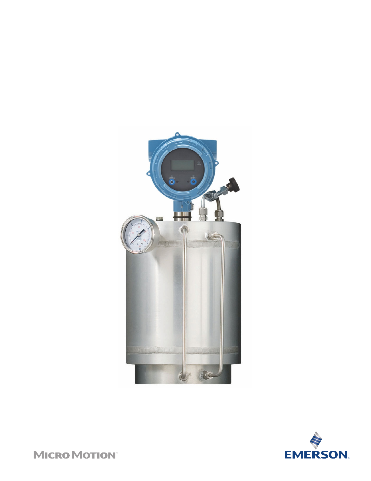
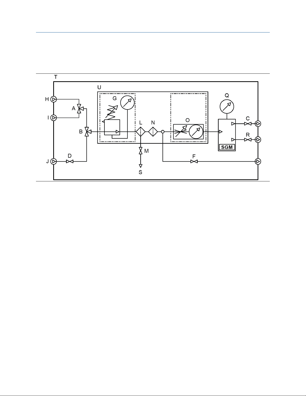
2.1 Functional view of the SGM
SGM components view
The following figures illustrate the major components of the SGM. Depending on the order, some
components may be shipped with the device or supplied by the customer.
Figure 2-1: Typical SGM installation
Configuration and Use Manual 9
STATUS
SCROLL SELECT
0
'
/
2
3
(
4
&
$79
5
0
6
*
1
)
%
$
+
,
-
Orientation and planning Configuration and Use Manual
March 2021 MMI-20020954
A. Calibration gas selector three-way valve
B. Process/Calibration gas selector three-way valve
C. Outlet two-way valve
D. Process gas inlet two-way valve
E. Chamber fill valve
F. Purge two-way valve
G. Pressure regulator with gauge
H. Calibration gas 1 inlet
I. Calibration gas 2 inlet
J. Process gas sampling point
K. Tubing work (not shown in diagram)
L. Coalescent filter
M. Coalescent filter drain two-way valve
N. Particle filter
O. Flow meter
P. Transmitter
Q. Reference chamber pressure indicator
R. Relief valve
S. Drain
ATV
Atmospheric Vent
10 Micro Motion Gas Specific Gravity Meters (SGM)
Configuration and Use Manual Orientation and planning
MMI-20020954 March 2021
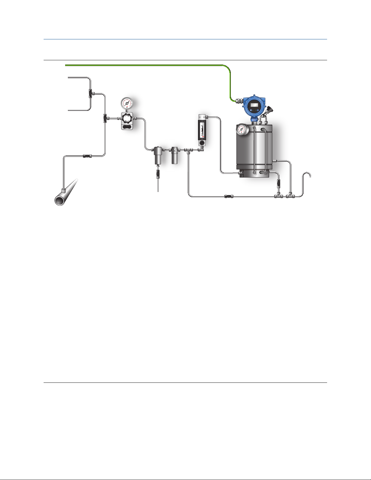
Complete sampling conditioning system
The SGM can be offered as a complete system shown in the following diagrams. The valves, filter, regulator,
and internal piping will all be included in the system with an optional electric heater.
Configuration and Use Manual 11

&$/*$6
&$/*$6
*$6
&$/*$6
STATUS
SCROLL SELECT
0
+
'
/
2
3
8
7
0
6
*
,
-
1
)
%
$
&
5
(
4
$79
Orientation and planning Configuration and Use Manual
March 2021 MMI-20020954
A. Calibration gas selector three-way valve
B. Process/Calibration gas selector three-way valve
C. Outlet two-way valve
D. Process gas inlet two-way valve
E. Chamber fill valve
F. Purge two-way valve
G. Pressure regulator with gauge
H. Calibration gas 1 inlet
I. Calibration gas 2 inlet
J. Process gas sample inlet
K. Tubing work (not shown in diagram)
L. Coalescent filter
M. Coalescent filter drain two-way valve
N. Particle filter
O. Flow meter
P. Transmitter
Q. Reference chamber pressure indicator
R. Relief valve
S. Drain
T. Enclosure
U. Mounting plate
ATV
Atmospheric Vent
12 Micro Motion Gas Specific Gravity Meters (SGM)

Configuration and Use Manual Orientation and planning
MMI-20020954 March 2021
2.2 Terms and definitions
Table 2-1: Terms used in meter setup and measurement
Term Definition or usage
Gas
Calibration gas Two or three pure, traceable calibration gases (99.9%) with a lower and higher
specific gravity/molecular weight as the process gas. Calibration gas can be the
same specific gravity as the process gas.
Reference gas The gas in the reference chamber. Typically, the process gas is used as the
reference gas.
Sample gas The gas stream to be measured by the meter.
Pressure
Control pressure The pressure of the reference gas in the reference chamber.
Line pressure The pressure in the main pipeline, independent of the meter.
Sample pressure The pressure of the sample gas after it passes through the pressure regulator.
Supply pressure The pressure of the sample gas before it passes through the pressure regulator.
Vent pressure The pressure required to force gas through the vent.
Measurement
Base density (standard density, normal
density)
Calorific value The amount of heat released during the combustion of a specified amount of a
Compressibility factor “z” The correction factor for interactive molecular behavior of non-ideal gas
Concentration (purity of binary gas
mixtures)
Energy flow The energy content of the process gas flowing through the pipe per unit of
Molecular weight The ratio of the average mass of one molecule of an element or compound to
Net mass flow rate The flow rate as measured in mass flow units and multiplied by the current
Net volume flow rate The flow rate as measured in volume flow units, corrected to base temperature
Relative density The ratio of the weight of a volume of gas (or gas mixture) to the weight of an
The absolute density of a gas at reference conditions (base temperature and
base pressure). Can be used to calculate standard volume flow from mass flow.
Measured in user-specified units.
gas. Measured in units of energy per units of the gas. Energy = calorific value.
mixtures.
In a binary gas mixture, the quantity of the primary gas in comparison to the
quantity of the secondary gas (contaminant). Measured in user-specified units.
time. Measured in units of energy per units of time.
one twelfth of the mass of an atom of carbon-12. Typically measured in g/mol.
concentration value.
and base pressure, and multiplied by the current concentration value.
equal volume of dry air, where the weights of both the gas and air are taken
under identical conditions of temperature and pressure. Unitless.
Specific gravity The ratio of the molecular weight of a gas (or gas mixture) to the molecular
weight of dry air. The molecular weight of dry air is normally assumed to be
28.96469. Unitless.
Configuration and Use Manual 13

Orientation and planning Configuration and Use Manual
March 2021 MMI-20020954
Table 2-1: Terms used in meter setup and measurement (continued)
Term Definition or usage
Wobbe index The ratio of the calorific value of a gas to its specific gravity. Measured in
volumetric units (BTU/SCF, and MJ/SCM).
2.3 Primary process variable: specific gravity, molecular weight, or relative density
The SGM can operate as a specific gravity meter, a molecular weight meter, or a relative density meter. Your
choice determines the set of process variables that the meter can report, the methods used to measure and
calculate them, and the data that you must supply during setup and configuration.
The primary process variable — specific gravity, molecular weight, or relative density — needs to be specified
as part of the order. However, you can change the primary process variable during calibration.
Related information
Primary process variable and available gas process variables
Primary process variable, gas process variables, and required data
2.3.1 Primary process variable and available gas process variables
The gas process variables that the SGM can report are determined by the primary process variable that you
select during calibration.
Available process variables
Specific gravity Unitless ✓ ✓
Molecular weight g/mol ✓ ✓
Relative density Unitless ✓
Base density g/cm³ ✓ ✓ ✓
Line density g/cm³ ✓ ✓ ✓
Line compressibility Unitless ✓ ✓ ✓
Base compressibility Unitless ✓ ✓ ✓
Calorific value MJ/m³ ✓ ✓
Wobbe index MJ/m³ ✓ ✓
Energy flow MJ/hr ✓ ✓
Concentration (gas purity) Concentration
Net mass flow rate g/sec ✓ ✓ ✓
Default
measurement unit
(% mass)
Specific gravity Molecular weight Relative density
✓ ✓ ✓
Primary process variable
Net volume flow rate l/sec ✓ ✓ ✓
14 Micro Motion Gas Specific Gravity Meters (SGM)

Configuration and Use Manual Orientation and planning
MMI-20020954 March 2021
2.3.2 Primary process variable, gas process variables, and required data
The gas process variables are calculated from a combination of measured variables, calculated variables,
process data from external devices, and user-specified values. For each process variable that you want the
meter to report, you must be able to supply all required external data and configuration values. Specific
requirements are determined by the primary process variable.
Note
The meter does not measure certain process variables directly. External devices are required for the following
process variables:
• Line pressure
• Gas composition (% CO, % CO2, % H2, % N2)
• Flow rate (mass or volume)
Note
• If you use temperature data from the meter, the data will represent the gas inside the measurement
chamber.
• If you use temperature data from an external device, the data will represent the gas at the location of the
temperature probe.
Table 2-2: Gas measurement when the primary process variable is specific gravity
Process variable to be reported Process data provided
by the SGM
Specific gravity Specific gravity
Molecular weight Specific gravity Molecular weight of air
Base density
Line density
NX 19
Line compressibility
NX 19 Mod
Molecular weight
Base compressibility
Temperature data from
meter (RTD)
Base density
Line compressibility
Base compressibility
Sample temperature
(RTD)
Specific gravity
Sample temperature
data from meter
(RTD)
Specific gravity
(1)
(1)
(1)
Required process data
from external devices
External temperature
Line pressure
External temperature
Line pressure
% CO2
% N2
External temperature
Line pressure
% CO2
% N2
Required userspecified values
Base pressure
Base temperature
(2)
Base pressure
Base temperature
(2)
Molecular weight of air
(2)
Configuration and Use Manual 15

Orientation and planning Configuration and Use Manual
March 2021 MMI-20020954
Table 2-2: Gas measurement when the primary process variable is specific gravity (continued)
Process variable to be reported Process data provided
by the SGM
Sample temperature
data from meter
(1)
NX 19 3h
(RTD)
Specific gravity
Calorific value
NX 19 Specific gravity
Base compressibility
NX 19 Mod Specific gravity
NX 19 3h
Specific gravity
Calorific value
Calorific Value AGA-5 Specific gravity
Wobbe Index
Mass units
Energy Flow
Volume units
Specific gravity
Calorific value
Line density
(3)
Calorific value
Line density
(4)
Calorific value
Required process data
from external devices
External temperature
(2)
Line pressure
% CO2
% N2
% CO2
% N2
% CO2
% N2
% CO2
% N2
% CO
% CO2
% H2
% N2
Mass flow rate (external
or calculated)
Volume flow rate
(external or calculated)
Required userspecified values
Molecular weight of air
Molecular weight of air
Base temperature
Base pressure
Base temperature
Base pressure
Molecular weight of air
Base temperature
Base pressure
(1) Used when you want process variables to represent the gas in the measurement chamber.
(2) Used when you want process variables to represent the gas at the location of the temperature probe.
(3) Required only if you plan to use the calculated mass flow measurement unit as the measurement unit for energy flow.
(4) Required only if you plan to use the calculated volume flow measurement unit as the measurement unit for energy
flow.
Table 2-3: Gas measurement when the primary process variable is molecular weight
Process variable to be reported
Process data provided
by the SGM
Molecular weight Molecular weight
Specific gravity Molecular weight Molecular weight of air
Base density
Molecular weight
Base compressibility
16 Micro Motion Gas Specific Gravity Meters (SGM)
Required process data
from external devices
Required userspecified values
Base pressure
Base temperature

Configuration and Use Manual Orientation and planning
MMI-20020954 March 2021
Table 2-3: Gas measurement when the primary process variable is molecular weight (continued)
Process variable to be reported
Line density
NX 19
NX 19 Mod
Line compressibility
NX 19 3h
SGERG-88
Process data provided
by the SGM
Sample temperature
data from meter
(1)
(RTD)
Molecular weight
Line compressibility
Sample temperature
(1)
Specific gravity
Sample temperature
data from meter
(1)
(RTD)
Sample temperature
data from meter
(1)
(RTD)
Specific gravity
Calorific value
Sample temperature
data from meter
(1)
(RTD)
Calorific value
Required process data
from external devices
External temperature
Line pressure
External temperature
Line pressure
% CO2
% N2
External temperature
Line pressure
% CO2
% N2
External temperature
Line pressure
% CO2
% N2
External temperature
Line pressure
% CO2
% H2
% N2
Required userspecified values
(2)
(2)
Molecular weight of air
(2)
(2)
Molecular weight of air
(2)
Molecular weight of air
Base temperature
Base pressure
Base temperature
Base pressure
Molecular weight of air
Base temperature
Base pressure
Base temperature
Base pressure
Base compressibility
NX 19 Specific gravity
NX 19 Mod Specific gravity
NX 19 3h
Specific gravity
Calorific value
SGERG-88 Calorific value
% CO2
% N2
% CO2
% N2
% CO2
% N2
% CO2
% H2
% N2
% CO
Calorific Value AGA-5
Line density
Specific gravity
% CO2
% H2
% N2
Wobbe Index
Specific gravity
Calorific value
Configuration and Use Manual 17

Orientation and planning Configuration and Use Manual
March 2021 MMI-20020954
Table 2-3: Gas measurement when the primary process variable is molecular weight (continued)
Process variable to be reported
Mass units
Energy Flow
Volume units Calorific value
(1) Used when you want process variables to represent the gas in the measurement chamber.
(2) Used when you want process variables to represent the gas at the location of the temperature probe.
Process data provided
by the SGM
Line density
Calorific value
Required process data
from external devices
Mass flow rate (direct
input or calculated)
Volume flow rate
(direct input or
calculated)
Required userspecified values
Table 2-4: Gas measurement when the primary process variable is relative density
Process variable to be reported
Relative density Relative density
Base density Relative density Base density of air
Line density
Line compressibility
Process data provided
by the SGM
Temperature data from
meter (RTD)
Base density
Line compressibility
Base compressibility
Temperature data from
meter (RTD)
Relative density
(1)
(1)
Required process data
from external devices
External temperature
Line pressure
External temperature
Line pressure
% CO2
% H2
% N2
Required userspecified values
(2)
Base temperature
Base pressure
(2)
% CO2
Base compressibility Relative density
(1) Used when you want process variables to represent the gas in the measurement chamber.
(2) Used when you want process variables to represent the gas at the location of the temperature probe.
% H2
% N2
Base temperature
Base pressure
2.4 Equations used to calculate specific gravity,
molecular weight, and relative density
2.4.1 Primary process variable = specific gravity
The following equations are used when the primary process variable is specific gravity.
Specific gravity
SG = K0 + K1 × τ + K2 × τ
SG
18 Micro Motion Gas Specific Gravity Meters (SGM)
Specific gravity of process gas
2

Configuration and Use Manual Orientation and planning
MMI-20020954 March 2021
K0, K1, K2
Calibration factors from the on-site calibration. If a two-point calibration was performed, K1 is
set to 0.
τ
Sensor time period (microseconds)
Molecular weight calculated from specific gravity
MW
SG
MW
Gas
Air
MW
Molecular weight of process gas (g/mol)
Specific gravity of process gas
Molecular weight of air (user-specified; default = 28.96469 g/mol)
Gas
= SG
Gas
× MW
Air
2.4.2 Primary process variable = molecular weight
The following equations are used when the primary process variable is molecular weight.
Molecular weight
2
MW
K0, K1, K2
MW = K0 + K1 × τ + K2 × τ
Molecular weight of process gas
Calibration factors from the on-site calibration. If a two-point calibration was performed, K1 is
set to 0.
τ
Sensor time period (microseconds)
Specific gravity calculated from molecular weight
MW
MW
Gas
Air
SG
MW
MW
Gas
Air
SG =
Specific gravity of process gas
Molecular weight of process gas (g/mol)
Molecular weight of air (user-specified; default = 28.96469 g/mol)
2.4.3 Primary process variable = relative density
The following equation is used when the primary process variable is relative density.
Relative density
2
RD
K0, K1, K2
τ
RD = K0 + K1 × τ + K2 × τ
Relative density of process gas
Calibration factors from the on-site calibration. If a two-point calibration was performed, K1 is
set to 0.
Sensor time period (microseconds)
Configuration and Use Manual 19

Orientation and planning Configuration and Use Manual
March 2021 MMI-20020954
20 Micro Motion Gas Specific Gravity Meters (SGM)

Configuration and Use Manual Quick start
MMI-20020954 March 2021
3 Quick start
3.1 Power up the transmitter
The transmitter must be powered up for all configuration and commissioning tasks, or for process
measurement.
Procedure
1. Ensure that all transmitter and sensor covers and seals are closed.
WARNING
To prevent ignition of flammable or combustible atmospheres, ensure that all covers and seals are
tightly closed. For hazardous area installations, applying power while housing covers are removed or
loose can cause an explosion.
2. Turn on the electrical power at the power supply.
The transmitter will automatically perform diagnostic routines. During this period, Alert 009 is active.
The diagnostic routines should complete in approximately 30 seconds.
Postrequisites
Although the sensor is ready to receive process fluid shortly after power-up, the electronics can take up to
10 minutes to reach thermal equilibrium. Therefore, if this is the initial startup, or if power has been off long
enough to allow components to reach ambient temperature, allow the electronics to warm up for
approximately 10 minutes before relying on process measurements. During this warm-up period, you may
observe minor measurement instability or inaccuracy.
3.2 Check meter status
Check the meter for any error conditions that require user action or that affect measurement accuracy.
Procedure
1. Wait approximately 10 seconds for the power-up sequence to complete.
Immediately after power-up, the transmitter runs through diagnostic routines and checks for error
conditions. During the power-up sequence, Alert A009 is active. This alert should clear automatically
when the power-up sequence is complete.
2. Check the status LED on the transmitter.
Table 3-1: Transmitter status reported by status LED
LED state Description Recommendation
Green No alerts are active. Continue with configuration or process
measurement.
Yellow One or more low-severity alerts are active. A low-severity alert condition does not affect
measurement accuracy or output behavior.
You can continue with configuration or
process measurement. If you choose, you can
identify and resolve the alert condition.
Configuration and Use Manual 21

Quick start Configuration and Use Manual
March 2021 MMI-20020954
Table 3-1: Transmitter status reported by status LED (continued)
LED state Description Recommendation
Flashing yellow Calibration in progress, or Known Density
Verification in progress.
Red One or more high-severity alerts are active. A high-severity alert condition affects
The measurement can fluctuate during the
calibration process or change as a result of the
calibration process. The alert will clear when
the calibration is complete. Check the
calibration results before continuing.
measurement accuracy and output behavior.
Resolve the alert condition before continuing.
Related information
View and acknowledge status alerts
Status alerts, causes, and recommendations
3.3 Make a startup connection to the transmitter
For all configuration tools except the display, you must have an active connection to the transmitter to
configure the transmitter.
Procedure
Identify the connection type to use, and follow the instructions for that connection type in the appropriate
appendix. Use the default communications parameters shown in the appendix.
Communications tool
Connection type to use Instructions
ProLink III Modbus/RS-485
HART/Bell 202
Field communicator HART/Bell 202 Using the field communicator with the
Using ProLink III with the transmitter
transmitter
Postrequisites
(Optional) Change the communications parameters to site-specific values.
ProLink III
Field communicator Configure → Manual Setup → HART → Communications
Device Tools → Configuration → Communications
Important
If you are changing communications parameters for the connection type that you are using, you will lose the
connection when you write the parameters to the transmitter. Reconnect using the new parameters.
22 Micro Motion Gas Specific Gravity Meters (SGM)

Configuration and Use Manual Introduction to configuration and commissioning
MMI-20020954 March 2021
4 Introduction to configuration and commissioning
4.1 Default values
Default values for your SGM meter are configured at the factory.
Important
Default values are based on your purchase order options. Therefore, the default values described in the
following tables may not be the factory default values configured for your system. For absolute accuracy,
refer to the configuration sheet that was shipped with your meter.
4.1.1 SGM default mA scaling values
Table 4-1: Primary variables
Variable Default 4 mA Default 20 mA
Specific gravity for calibration range 1 0 0.4
Specific gravity for calibration range 2 0 0.4
Specific gravity for calibration range 3 0 0.4
Specific gravity for calibration range 4 0 0.4
Molecular weight for calibration range10 g/mol 28.96469 g/mol
Molecular weight for calibration range20 g/mol 28.96469 g/mol
Molecular weight for calibration range30 g/mol 28.96469 g/mol
Molecular weight for calibration range40 g/mol 28.96469 g/mol
Sensor time period 400 us 1200 us
Table 4-2: Derived variables
Variable Default 4 mA Default 20 mA
Base density 0.000 g/cm3 0.400 g/cm3
Calorific value 20 MJ/Nm3 60 MJ/Nm3
Wobbe index 20 MJ/Nm3 60 MJ/Nm3
Sample temperature -50.000°C
-58°F
Drive gain 0.000 % 100.000 %
External temperature -50.000°C
-58.00000°F
Configuration and Use Manual 23
200.000°C
392°F
200.000°C
392.0000°F

Introduction to configuration and commissioning Configuration and Use Manual
March 2021 MMI-20020954
Table 4-2: Derived variables (continued)
Variable Default 4 mA Default 20 mA
External pressure 0.000 PSIg 1450.377 PSIg
Line density 0 g/cm3 0.4 g/cm3
User-defined calculation output 0 100
%CO
%N
%H
2
2
2
0 % 100.00 %
0 % 100.00 %
0 % 100.00 %
%CO 0 % 100.00 %
Table 4-3: Concentration measurement enabled
Variable Default 4 mA Default 20 mA
Gas purity concentration for curve 1 00.00 % 100.00 %
Gas purity concentration for curve 2 00.00 % 100.00 %
Gas purity concentration for curve 3 00.00 % 100.00 %
Gas purity concentration for curve 4 00.00 % 100.000 %
Table 4-4: Flow input enabled
Variable Default 4 mA Default 20 mA
Mass flow rate (calculated) -200.00 g/sec 200.00 g/sec
Mass flow rate (external) -200.00 g/sec 200.00 g/sec
Volume flow rate (calculated) -0.42378 SCFM 0.42378 SCFM
Volume flow rate (external) -0.2 l/sec 0.2 l/sec
Table 4-5: SGM default variables
Default variable Output option A Output options B and C
Primary Variable (PV), mA1 Sample Temperature • Specific Gravity for Calibration Set 1
• Molecular Weight for Calibration Set 1
• Relative Density
Secondary Variable (SV), mA2 Time Period B Sample Temperature
Tertiary Variable (TV) • Specific Gravity for
Calibration Set 1
• Molecular Weight for
Calibration Set 1
• Relative Density
Quaternary Variable (QV) Drive Gain Drive Gain
24 Micro Motion Gas Specific Gravity Meters (SGM)
Sensor Time Period
&%
'
(
$
Configuration and Use Manual Introduction to configuration and commissioning
MMI-20020954 March 2021
4.2 Enable access to the off-line menu of the display
ProLink III Device Tools → Configuration → Transmitter Display → Display Security
Field communicator Configure → Manual Setup → Display → Display Menus → Offline Menu
By default, access to the off-line menu of the display is enabled. If it is disabled, you must enable it if you want
to use the display to configure the transmitter.
Restriction
You cannot use the display to enable access to the off-line menu. You must make a connection from another
tool.
4.3 Disable HART security
If you plan to use HART protocol to configure the device, HART security must be disabled. HART security is
disabled by default, so you may not need to do this.
Prerequisites
• Strap wrench
• 3 mm hex key
Procedure
1. Power down the meter.
2. Using the strap wrench, loosen the grub screws and remove the transmitter end-cap.
Figure 4-1: Transmitter with end-cap removed
A. Transmitter end-cap
B. 3 mm hex key
C. Safety spacer
D. HART security switch
E. Unused
3. Using the hex key, remove the safety spacer.
Configuration and Use Manual 25

Introduction to configuration and commissioning Configuration and Use Manual
March 2021 MMI-20020954
4. Move the HART security switch to the OFF position (up).
The HART security switch is the switch on the left.
5. Replace the safety spacer and end-cap.
6. Power up the meter.
4.4 Set the HART lock
If you plan to use a HART connection to configure the device, you can lock out all other HART masters. If you
do this, other HART masters will be able to read data from the device but will not be able to write data to the
device.
Restriction
HART lock is only available:
• When you are using a field communicator or AMS
• With a HART 7 host
Procedure
1. Choose Configure → Manual Setup → Security → Lock/Unlock Device.
2. If you are locking the meter, set Lock Option as desired.
Option
Permanent Only the current HART master can make changes to the device. The device will remain
Temporary Only the current HART master can make changes to the device. The device will remain
Lock All No HART masters are allowed to make changes to the configuration. Before changing
Postrequisites
To avoid future confusion or difficulties, ensure that the device is unlocked after you have completed your
tasks.
Description
locked until manually unlocked by a HART master. The HART master can also change
Lock Option to Temporary.
locked until manually unlocked by a HART master, or a power-cycle or device reset is
performed. The HART master can also change Lock Option to Permanent.
Lock Option to Permanent or Temporary, the device must be unlocked. Any HART
master can be used to unlock the device.
4.5 Restore the factory configuration
The SGM is a field-configured device. Therefore, attempts to restore the factory configuration will result in an
error since no factory configuration is loaded into the SGM electronics.
26 Micro Motion Gas Specific Gravity Meters (SGM)

Configuration and Use Manual Purging and calibration
MMI-20020954 March 2021
5 Purging and calibration
5.1 On-site setup requirements
The SGM is shipped with an empty reference chamber and no calibration factors. The SGM cannot be factory
calibrated. Instead, you must perform calibration in the field using one of two on-site setup procedures. A
setup procedure involves purging and filling the reference chamber with your process gas, then using known
calibration gases.
Related information
Prepare for SGM purging and calibration
Purge and purge-cycle the SGM device
Calibrate the SGM device
Review data for all calibrations
Select the active calibration
5.2 Prepare for SGM purging and calibration
Before you begin these procedures, you must:
• Know the primary process variable that you want to use. In other words, you must know whether the
meter will operate as a specific gravity meter, a molecular weight meter, or a relative density meter.
• Know if you need a two-point or three-point calibration. Most applications require a two-point calibration.
For a few exceptions, a three-point calibration may be required.
• Prepare the calibration gases.
• Know the appropriate control pressure.
• Be able to control sample pressure and vent pressure.
Related information
Three-point calibration
5.2.1 Primary process variable: specific gravity, molecular weight,
or relative density
The SGM can operate as a specific gravity meter, a molecular weight meter, or a relative density meter. Your
choice determines the set of process variables that the meter can report, the methods used to measure and
calculate them, and the data that you must supply during setup and configuration.
The primary process variable — specific gravity, molecular weight, or relative density — needs to be specified
as part of the order. However, you can change the primary process variable during calibration.
Related information
Primary process variable and available gas process variables
Primary process variable, gas process variables, and required data
Configuration and Use Manual 27

Purging and calibration Configuration and Use Manual
March 2021 MMI-20020954
5.2.2 Two-point calibration vs. three-point calibration
Your choice of two-point calibration or three-point calibration depends on how many process gases you are
using.
Two-point
calibration
Three-point
calibration
Related information
Three-point calibration
Two gases are used for calibration. Standard and most common applications require
only two calibration points to get the best accuracy. A two-point calibration produces
two calibration factors: K0 and K2. K1 is set to 0.
Three gases are used for calibration. Three-point calibrations are less common. For
more information, see Three-point calibration.
5.2.3 Calibration gases
The calibration gases should match the main constituents of your process gas. The gases must cover the
lower and upper SG/MW range of the process gas and have similar compressibility characteristics.
Gas types and requirements
Analytical calibration gases are specified by purity grade or number of 9’s. “High purity” or “4.5 nines
(99.995%)” grades are good choices for calibrating the SGM.
For example, if the SGM is measuring the specific gravity of natural gas, use pure nitrogen and pure methane
as calibration gases.
Table 5-1: Examples of calibration gases
Application Two-point calibration gases
Natural gas Methane and nitrogen
Hydrogen purity Hydrogen and nitrogen
Fuel to air ratio Methane and propane
Equipment requirements
• Cylinders must have a gauge regulator and hose.
• The hose needs to have a 0.25 in (6.4 mm) Swagelok® female connector.
• The minimum gas bottle size for each of the calibration gases should be no less than 4.5 gallons (17 liters)
at a 20% higher of nominal pressure at the outlet of the regulator depending on the application.
Most gas suppliers can provide these items.
28 Micro Motion Gas Specific Gravity Meters (SGM)
Configuration and Use Manual Purging and calibration
MMI-20020954 March 2021
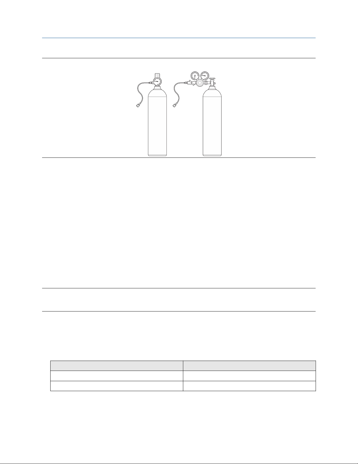
Figure 5-1: Examples of cylinders with pressure regulators, hoses, and compression fittings
Data entry for gas calibration
During calibration, you will be required to enter data for each calibration gas:
• If the SGM is operating as a specific gravity meter, you must enter the specific gravity of the gas.
During calibration, you must be able to flow each calibration gas through the meter in the order of their
specific gravity, lowest to highest.
• If the SGM is operating as a relative density meter, you must enter the relative density of the calibration
gas.
• If the SGM is operating as a molecular weight meter, you must enter the molecular weight of the gas.
5.2.4 Pressure
A meter with the sampling conditioning system includes a pressure regulator with indicator that:
• Controls the inlet sample pressure
• Allows you to verify sample pressure
Note
All SGM models come with an included pressure gauge that identifies only the reference chamber pressure
that is used for pressure and compressibility compensation.
For SGM models without the sampling conditioning system, a pressure regulator with indicator must be
installed by the customer.
The pressure in the system must meet the following requirements:
• The maximum sample inlet pressure (the pressure regulator with gauge in Pressure) for the different SGM
models should not exceed:
SGM model
SGM2, SGM3 (without pressure regulator) 122 psia (8.41 bara)
Pressure rating
SGM4 (with pressure regulator) 1,450 psia (100 bara)
• Reference chamber maximum pressure: 101 psia (6.96 bara)
Configuration and Use Manual 29

Purging and calibration Configuration and Use Manual
March 2021 MMI-20020954
Determine the reference chamber pressure
The reference chamber pressure must be appropriate to your application. You must know the desired
reference chamber pressure before you begin the purge and calibration process. The reference chamber
pressure also affects the inlet sample supply pressure and the outlet vent pressure that you must maintain in
the system.
Guidelines for reference chamber pressure
Use the following guidelines for reference chamber pressure:
• Between 17 psia (1.17 bara) and 101 psia (7 bara), at 68 °F (20 °C)
• Less than the inlet sample pressure by 15% to 25%
• Greater than the outlet vent pressure
These pressure settings work for most applications. Use them as starting point, or use them to calculate
reference chamber pressure using data that is specific to your process.
Related information
Calculate measurement errors using reference chamber pressure
5.2.5 Multiple calibrations
The SGM can store calibrations for up to four different process gases or ranges. Each calibration is generated
by an independent calibration procedure and contains an independent set of calibration coefficients. This
feature allows you to switch between process gases or ranges without recalibrating the device.
If you plan to use more than one calibration:
• Perform all calibrations using the same measurement option: specific gravity, molecular weight, or
relative density.
• Set calibrations as either two-point calibrations or three-point calibrations.
• Complete each calibration before beginning the next calibration.
• Choose to add calibrations at a later time. You do not need to perform all calibrations at the same time.
Important
It is possible to use a different reference chamber pressure for each calibration. If you do, change the
reference chamber pressure in the meter whenever you change the active calibration. If you do not change
the reference chamber pressure to match the active calibration, measurement accuracy will be affected.
Calibration ranges
• If you have a specific gravity meter, the meter will automatically calculate the specific gravity output
variable for all four ranges during operation.
• If you have a molecular weight meter, the meter will automatically calculate the molecular weight output
variable for all four ranges during operation.
• If you have a relative density meter, only one calibration is applied at a time. A control selects the active
calibration.
• For specific gravity and molecular weight meters — energy, energy flow, compressibility, and Wobbe index
are calculated only from the active calibration. Gas purity is automatically calculated for the associated
30 Micro Motion Gas Specific Gravity Meters (SGM)
Loading...