

Reference Manual
00809-0100-4075, Rev BA
October 2010
Smart Wireless THUM™ Adapter
www.rosemount.com


Reference Manual
NOTICE
00809-0100-4075, Rev BA
October 2010
Smart Wireless THUM Adapter
Smart Wireless THUM™ Adapter
Smart Wireless THUM™ Adapter Hardware Revision 1
®
HART
Device Revision 1
Field Communicator Field Device Revision Dev v2.5 DD v4
Read this manual before working with the product. For personal and system safety, and for
optimum product performance, make sure to thoroughly understand the contents before
installing, using, or maintaining this product.
The United States has two toll-free assistance numbers and one international number.
Customer Central
1 800 999 9307 (7:00 a.m. to 7:00 p.m. CST)
National Response Center
1 800 654 7768 (24 hours a day)
Equipment service needs
International
1 952 906 8888
The products described in this document are NOT designed for nuclear-qualified
applications.
Using non-nuclear qualified products in applications that require nuclear-qualified hardware
or products may cause inaccurate readings.
For information on Rosemount nuclear-qualified products, contact an Emerson Process
Management Sales Representative.
Explosions could result in death or serious injury:
Installation of this transmitter in an explosive environment must be in accordance with the
appropriate local, national, and international standards, codes, and practices. Please review
the Product Certifications section for any restrictions associated with a safe installation.
• Before connecting a Field Communicator in an explosive atmosphere, ensure the
instruments are installed in accordance with intrinsically safe or non-incendive field
wiring practices.
Electrical shock can result in death or serious injury:
• Avoid contact with the leads and terminals. High voltage that may be present on
leads can cause electrical shock.
This device complies with Part 15 of the FCC Rules. Operation is subject to the following
conditions. This device may not cause harmful interference. This device must accept any
interference received, including interference that may cause undesired operation.
This device must be installed to ensure a minimum antenna separation distance of 20 cm
from all persons.

Smart Wireless THUM Adapter
NOTICE
NOTICE
The THUM and all other wireless devices should be installed only after the Smart Wireless
Gateway has been installed and is functioning properly. Wireless devices should also be
powered up in order of proximity from the Smart Wireless Gateway, beginning with the
closest. This will result in a simpler and faster network installation.
During normal operation, or in fault condition, the THUM will cause a 2.5 V drop in the
connected loop. It is important to ensure that the power supply can provide at least 2.5 V
more than the lift off voltage of the wired device to make sure it works properly with the
THUM installed. To determine the lift off voltage for the wired device, review the wired
device operation and installation manual.
Reference Manual
00809-0100-4075, Rev BA
October 2010

Reference Manual
00809-0100-4101, Rev BA
October 2010
Smart Wireless THUM Adapter
Table of Contents
SECTION 1
Introduction
SECTION 2
Configuration
Safety Messages. . . . . . . . . . . . . . . . . . . . . . . . . . . . . . . . . . . . . . . . . 1-1
Overview . . . . . . . . . . . . . . . . . . . . . . . . . . . . . . . . . . . . . . . . . . . . . . . 1-2
Considerations. . . . . . . . . . . . . . . . . . . . . . . . . . . . . . . . . . . . . . . . . . . 1-3
Temperature Limits . . . . . . . . . . . . . . . . . . . . . . . . . . . . . . . . . . 1-3
Power Up Sequence . . . . . . . . . . . . . . . . . . . . . . . . . . . . . . . . . 1-3
THUM Adapter Position. . . . . . . . . . . . . . . . . . . . . . . . . . . . . . . 1-3
Conduit Entry. . . . . . . . . . . . . . . . . . . . . . . . . . . . . . . . . . . . . . . 1-4
M20 Conduit Adapter . . . . . . . . . . . . . . . . . . . . . . . . . . . . . . . . 1-4
Field Communicator Connections . . . . . . . . . . . . . . . . . . . . . . . 1-4
Power Supply . . . . . . . . . . . . . . . . . . . . . . . . . . . . . . . . . . . . . . 1-4
Load Resistor . . . . . . . . . . . . . . . . . . . . . . . . . . . . . . . . . . . . . . 1-4
Service Support. . . . . . . . . . . . . . . . . . . . . . . . . . . . . . . . . . . . . . . . . . 1-5
Product Recycling/Disposal. . . . . . . . . . . . . . . . . . . . . . . . . . . . . . . . . 1-5
Safety Messages. . . . . . . . . . . . . . . . . . . . . . . . . . . . . . . . . . . . . . . . . 2-1
Connections. . . . . . . . . . . . . . . . . . . . . . . . . . . . . . . . . . . . . . . . . . . . . 2-2
Device Sensor Configuration. . . . . . . . . . . . . . . . . . . . . . . . . . . . . . . . 2-2
Field Communicator . . . . . . . . . . . . . . . . . . . . . . . . . . . . . . . . . 2-2
AMS Wireless Configurator. . . . . . . . . . . . . . . . . . . . . . . . . . . . 2-2
Connection Diagrams . . . . . . . . . . . . . . . . . . . . . . . . . . . . . . . . . . . . . 2-2
Bench Hook-up . . . . . . . . . . . . . . . . . . . . . . . . . . . . . . . . . . . . . 2-2
Field Hook-Up . . . . . . . . . . . . . . . . . . . . . . . . . . . . . . . . . . . . . . 2-2
Device Network Configuration. . . . . . . . . . . . . . . . . . . . . . . . . . . . . . . 2-3
HART Tree. . . . . . . . . . . . . . . . . . . . . . . . . . . . . . . . . . . . . . . . . . . . . . 2-5
SECTION 3
Mounting
SECTION 4
Commissioning
SECTION 5
Operation and
Maintenance
Safety Messages. . . . . . . . . . . . . . . . . . . . . . . . . . . . . . . . . . . . . . . . . 3-1
Mounting . . . . . . . . . . . . . . . . . . . . . . . . . . . . . . . . . . . . . . . . . . . . . . . 3-2
Loop Current Test . . . . . . . . . . . . . . . . . . . . . . . . . . . . . . . . . . . . . . . 3-14
AMS. . . . . . . . . . . . . . . . . . . . . . . . . . . . . . . . . . . . . . . . . . . . . 3-14
Field Communicator . . . . . . . . . . . . . . . . . . . . . . . . . . . . . . . . 3-14
AMS. . . . . . . . . . . . . . . . . . . . . . . . . . . . . . . . . . . . . . . . . . . . . 3-15
Field Communicator . . . . . . . . . . . . . . . . . . . . . . . . . . . . . . . . 3-15
Safety Messages. . . . . . . . . . . . . . . . . . . . . . . . . . . . . . . . . . . . . . . . . 4-1
Device Network Configuration. . . . . . . . . . . . . . . . . . . . . . . . . . . . . . . 4-2
AMS. . . . . . . . . . . . . . . . . . . . . . . . . . . . . . . . . . . . . . . . . . . . . . 4-2
Field Communicator . . . . . . . . . . . . . . . . . . . . . . . . . . . . . . . . . 4-2
Field Communicator . . . . . . . . . . . . . . . . . . . . . . . . . . . . . . . . . 4-3
Smart Wireless Gateway. . . . . . . . . . . . . . . . . . . . . . . . . . . . . . 4-3
AMS Wireless Configurator. . . . . . . . . . . . . . . . . . . . . . . . . . . . 4-4
Troubleshooting. . . . . . . . . . . . . . . . . . . . . . . . . . . . . . . . . . . . . 4-4
Reference Information. . . . . . . . . . . . . . . . . . . . . . . . . . . . . . . . 4-4
Safety Messages. . . . . . . . . . . . . . . . . . . . . . . . . . . . . . . . . . . . . . . . . 5-1
Startup Sequence . . . . . . . . . . . . . . . . . . . . . . . . . . . . . . . . . . . . . . . . 5-2
Advanced Setup . . . . . . . . . . . . . . . . . . . . . . . . . . . . . . . . . . . . . . . . . 5-2
TOC-1

Smart Wireless THUM Adapter
Reference Manual
00809-0100-4101, Rev BA
October 2010
SECTION 6
Troubleshooting
APPENDIX A
Reference Data
APPENDIX B
Product Certifications
Overview . . . . . . . . . . . . . . . . . . . . . . . . . . . . . . . . . . . . . . . . . . . . . . . 6-1
Functional Specifications. . . . . . . . . . . . . . . . . . . . . . . . . . . . . . . . . . .A-1
Physical Specifications . . . . . . . . . . . . . . . . . . . . . . . . . . . . . . . . . . . .A-1
Performance Specifications. . . . . . . . . . . . . . . . . . . . . . . . . . . . . . . . .A-2
Dimensional Drawings. . . . . . . . . . . . . . . . . . . . . . . . . . . . . . . . . . . . .A-3
Ordering Information . . . . . . . . . . . . . . . . . . . . . . . . . . . . . . . . . . . . . .A-5
Accessories and Spare Parts . . . . . . . . . . . . . . . . . . . . . . . . . . . . . . .A-5
North American Certifications . . . . . . . . . . . . . . . . . . . . . . . . . .B-1
CSA - Canadian Standards Association . . . . . . . . . . . . . . . . . .B-2
European Certifications. . . . . . . . . . . . . . . . . . . . . . . . . . . . . . .B-2
IECEx Certifications . . . . . . . . . . . . . . . . . . . . . . . . . . . . . . . . .B-3
INMETRO Certifications . . . . . . . . . . . . . . . . . . . . . . . . . . . . . .B-3
China (NEPSI) Certifications. . . . . . . . . . . . . . . . . . . . . . . . . . .B-3
CCoE Certifications. . . . . . . . . . . . . . . . . . . . . . . . . . . . . . . . . .B-3
KOSHA Certifications . . . . . . . . . . . . . . . . . . . . . . . . . . . . . . . .B-3
GOST Certifications . . . . . . . . . . . . . . . . . . . . . . . . . . . . . . . . .B-3
TOC-2

Reference Manual
00809-0100-4075, Rev BA
October 2010
Smart Wireless THUM Adapter
Section 1 Introduction
Safety Messages . . . . . . . . . . . . . . . . . . . . . . . . . . . . . . . . . page 1-1
Overview . . . . . . . . . . . . . . . . . . . . . . . . . . . . . . . . . . . . . . .page 1-2
Considerations . . . . . . . . . . . . . . . . . . . . . . . . . . . . . . . . . .page 1-3
Service Support . . . . . . . . . . . . . . . . . . . . . . . . . . . . . . . . . page 1-5
Product Recycling/Disposal . . . . . . . . . . . . . . . . . . . . . . .page 1-5
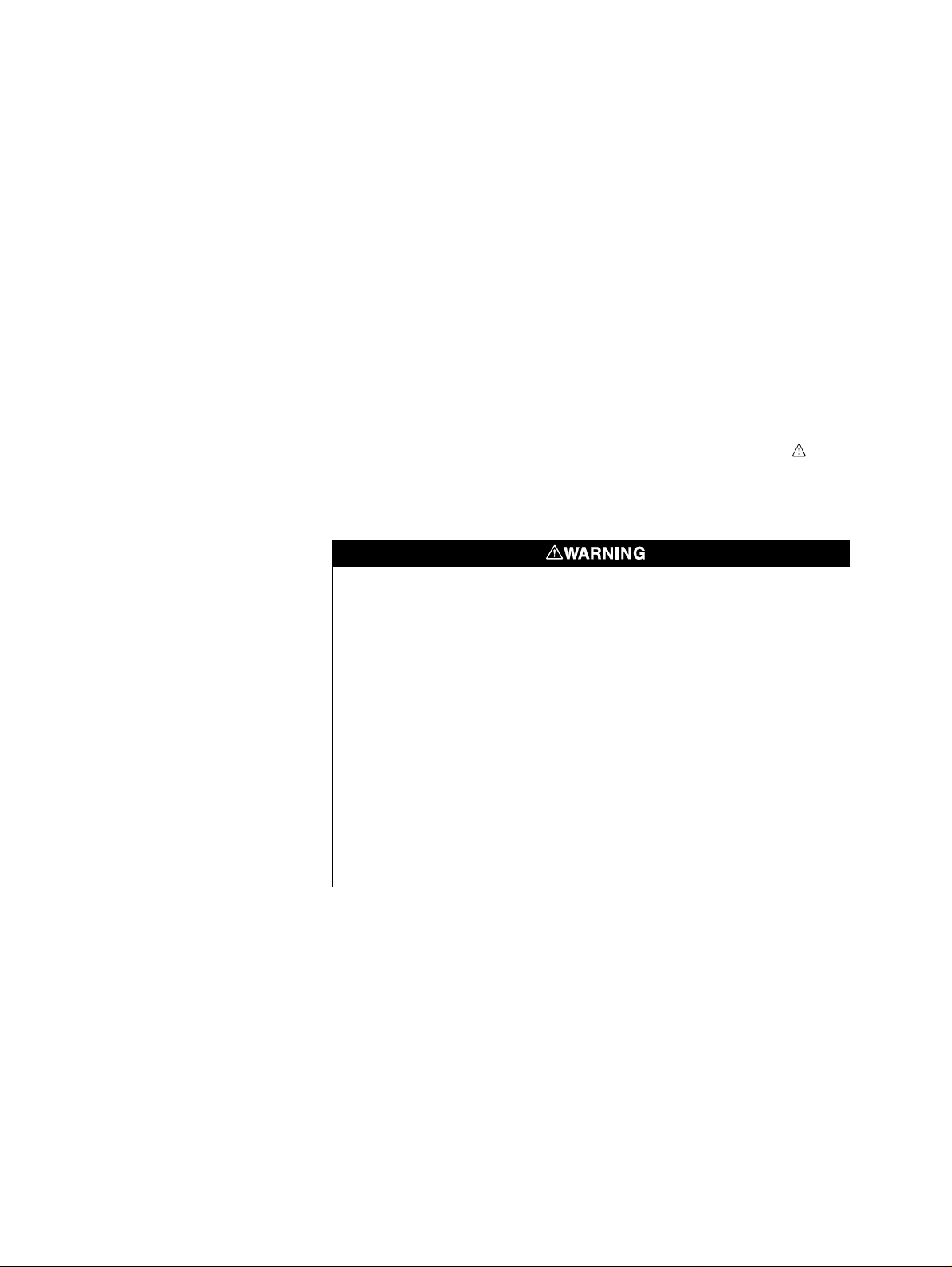
SAFETY MESSAGES Instructions and procedures in this section may require special precautions to
ensure the safety of the personnel performing the operations. Infor mation that
potentially raises safety issues is indicated by a warning symbol ( ). Please
refer to the following safety messages before performing an operation
preceded by this symbol.
Warnings
Failure to follow these installation guidelines could result in death or
serious injury.
• Make sure only qualified personnel perform the installation.
Explosions could result in death or serious injury.
• Before connecting a Field Communicator in an explosive atmosphere, make sure
the instruments are installed in accordance with intrinsically safe or non-incendive
field wiring practices.
• Verify that the operating atmosphere of the transmitter is consistent with the
appropriate hazardous locations certifications.
Electrical shock could cause death or serious injury.
• Use extreme caution when making contact with the leads and terminals.
1-1

Reference Manual
00809-0100-4075, Rev BA
Smart Wireless THUM Adapter
October 2010
OVERVIEW
Manual This manual is designed to assist in the installation, operation, and
maintenance of the Smart Wireless THUM™ Adapter.
Section 1: Introduction
• Manual and Transmitter Overview
• Considerations
• Return of Materials
Section 2: Configuration
• Device Sensor Configuration
• Device Network Configuration
Section 3: Mounting
• Mount the Sensor
• Sensor Assembly/Leads
• Grounding
Section 4: Commissioning
• Network Status
• Verify Operation
Section 5: Operation and Maintenance
• Startup Sequence
• Advanced Setup
Appendix A: Reference Data
• Specifications
• Dimensional Drawings
• Ordering Information
Appendix B: Product Certifications
• Product Certifications
• Installation Drawings
Features • An installation-ready solution that provides rich wireless HART
• Works with any 2- or 4-wire HART devices
• Flexibility to meet your most demanding applications
• Wireless output with >99% data reliability delivers rich HART data,
protected by industry leading security
• Gain access to additional HART information, such as diagnostics or
multi-variable data
• Add wireless to almost any measurement point w ith ou t affecting the
approval of the sub-device
• IEC 62591 (WirelessHART™) capabilitie s exten d the full benefits of
PlantWeb
®
to previously inaccessible locations
®
data
1-2

Reference Manual
00809-0100-4075, Rev BA
October 2010
Smart Wireless THUM Adapter
CONSIDERATIONS
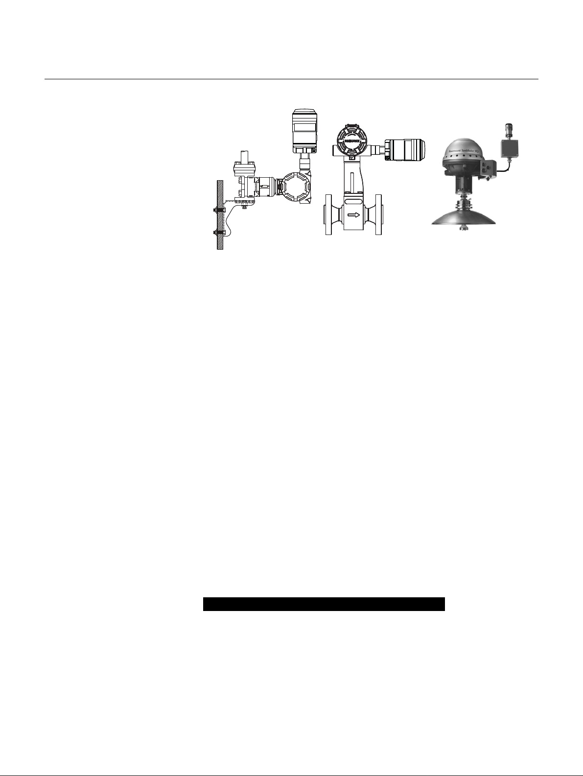
General The Smart Wireless THUM Adapter is connected to a HART sub-device. With
simple HART configuration, the THUM transmits the HART information from
the sub-device into the Wireless network.
Commissioning The THUM can be commissioned before or after installation. It may be useful
to bench commission the THUM before installation to ensure proper op eration
and to become familiar with the functionality. The instruments should be
installed in accordance with intrinsically safe or non-incendive field wiring
practices, when required. The THUM Adapter is powered when connected to
a powered loop.
Mechanical When choosing an installation location and position for the transmitter, take
into account access to the device. For best performance, the antenna should
be vertical and have some space between objects in a parallel metal plane
such as a pipe or metal framework, as the pipes or framework m ay adve rsely
affect the performance of the antenna.
Electrical The THUM Adapter is connected into a powered 4–20 mA loop, powering
itself by scavenging power . The THUM Adapter causes a vo ltage drop across
the loop. The drop is linear from 2.25 volts at 3.5 mA to 1.2 volt s at 25 mA, but
does not effect the 4–20 mA signal on the loop. Under fault conditions, the
maximum voltage drop is 2.5 volts.
Environmental Verify that the operating environment of the transmitter is consistent with the
appropriate hazardous locations certifications.
Temperature Limits
Operating Limit Storage Limit
–40 to 185 °F
–40 to 85 °C
–40 to 185 °F
–40 to 85 °C
Wireless Considerations Power Up Sequence
Power should not be applied to any wireless device until the Smart Wireless
Gateway (“Gateway”) is installed and functioning properly. Wireless devices
should also be powered up in order of proximity from the Gateway, beginning
with the closest. This will result in a simpler and faster network installation.
Enable Active Advertising on the Gateway to ensure that new devices join the
network faster. For more information see the Smart Wireless Gateway Manual
(Doc. No. 00809-0200-4420).
THUM Adapter Position
If possible, the THUM Adapter should be positioned vertically, either straight
up or straight down, and it should be approximately 3 ft. (1 m) from any large
structure, building, or conductive surface to allow for clear communication to
other devices. If the THUM Adapter is mounted horizontally, wireless
communication range may be decreased.
1-3
Smart Wireless THUM Adapter
Figure 1-1. THUM Adapter
Position
Conduit Entry
When installing the THUM Adapter into the conduit entry of a wired device,
use an approved thread sealant. Thread sealant provides a water tight se al.
The thread sealant also provides a lubrication to ensure easy removal of the
THUM Adapter.
Reference Manual
00809-0100-4075, Rev BA
October 2010
M20 Conduit Adapter
When using the M20 Conduit Adapter on the THUM Adapter, use an
approved thread sealant and tighten wrench tight to the THUM Adapter. When
installing the M20 conduit adapter into a condu it tighten to 3 2.5 Nm/25 ft -lb. to
ensure water tight seal.
Field Communicator Connections
In order for the Field Communicator to interface with the THUM Adapter, the
wired device must be powered. The Field Communicator must be put into poll
mode and should use the THUM Adapter address of 63.
Power Supply
Minimum loop load of 250 Ohms.
The THUM Adapter communicates and derives power from a standard 4-20
mA/HART loop. The THUM Adapter causes a small voltage drop on the loop
which is linear from 2.25 V at 3.5 mA to 1.2 V at 25 mA. Under fault
conditions, the maximum voltage drop is 2.5 V. The THUM Adapter will not
affect the 4-20 mA signal under normal or fault conditions as long as the loop
has at least a 2.5 V margin at the maximum loop current (25 mA for a typical
4-20 mA/HART device).
Limit the power supply to 0.5 Amps maximum, and voltage to 55 Vdc.
Loop Current THUM Adapter voltage drop
3.5 mA
25 mA
2.25 V
1.2 V
1-4
Load Resistor
If required, add a load resistor as shown in Figure 3-20, 3-22, and 3-24. The
resistor should be adequately rated for the application (1W minimum) and be
compatible with the supplied splice connector which accepts wire sizes from
14 to 22 AWG.
When adding a load resistor, ensure that uninsulated conductors do not
contact the enclosure and/or other exposed m etal parts.

Reference Manual
00809-0100-4075, Rev BA
October 2010
Smart Wireless THUM Adapter
SERVICE SUPPORT To expedite the return process outside of North America, contact your
Emerson Process Management representative.
Within the United States, call the Emerson Process Management Response
Center toll-free number 1 800 654 7768. The center, which is available 24
hours a day, will assist you with any needed information or materials.
The center will ask for product model and serial numbers, and will provide a
Return Material Authorization (RMA) number. The center will also ask for the
process material to which the product was last exposed.
Individuals who handle products exposed to a hazardous substance can avoid injury if they
are informed of, and understand, the hazard. If the product being returned was exposed to a
hazardous substance as defined by OSHA, a copy of the required Material Safety Data
Sheet (MSDS) for each hazardous substance identified must be included with the returned
goods.
PRODUCT RECYCLING/DISPOSAL
Recycling of equipment and packaging should be taken into consideration
and disposed of in accordance with local and national legislation/regulations.
1-5

Smart Wireless THUM Adapter
Reference Manual
00809-0100-4075, Rev BA
October 2010
1-6
Reference Manual
00809-0100-4075, Rev BA
October 2010
Smart Wireless THUM Adapter
Section 2 Configuration
Safety Messages . . . . . . . . . . . . . . . . . . . . . . . . . . . . . . . . . page 2-1
Connections . . . . . . . . . . . . . . . . . . . . . . . . . . . . . . . . . . . . page 2-2
Device Sensor Configuration . . . . . . . . . . . . . . . . . . . . . . page 2-2
Connection Diagrams . . . . . . . . . . . . . . . . . . . . . . . . . . . . . page 2-2
Device Network Configuration . . . . . . . . . . . . . . . . . . . . . page 2-3
HART Tree . . . . . . . . . . . . . . . . . . . . . . . . . . . . . . . . . . . . . .page 2-5
SAFETY MESSAGES Instructions and procedures in this section may require special precautions to
ensure the safety of the personnel performing the operations. Infor mation that
potentially raises safety issues is indicated by a warning symbol ( ). Please
refer to the following safety messages before performing an operation
preceded by this symbol.
Warnings
Failure to follow these installation guidelines could result in death or serious injury:
• Only qualified personnel should perform the installation
Explosions could result in death or serious injury.
• Before connecting a Field Communicator in an explosive atmosphere, make
sure that the instruments are installed in accordance with intrinsically safe or
non-incendive field wiring practices
• Verify that the operating atmosphere of the transmitter is consistent with the
appropriate hazardous locations certifications
Electrical shock could cause death or serious injury.
• Use extreme caution when making contact with the leads and terminals
This device complies with Part 15 of the FCC Rules. Operation is subject to the
following conditions: This device may not cause harmful interference. This device must
accept any interference received, including interference that may cause undesired
operation.
This device must be installed to ensure a minimum antenna separation distance of 20
cm from all persons.
2-1
Reference Manual
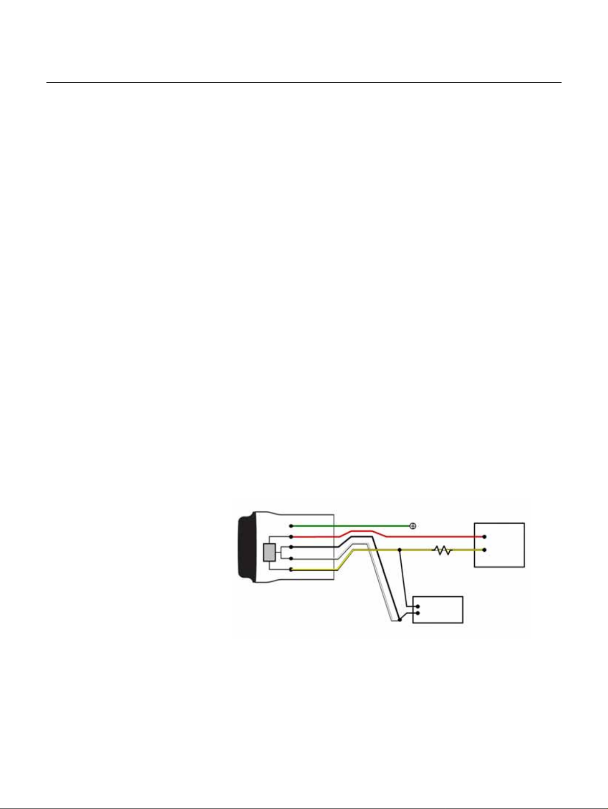
Ground
-
20 mA
Current
Source
HART
Modem
THUM Adapter
Green
Red
Black
White
Yellow
+
250 Ohm Resistor not
required, but may be
used to verify current
00809-0100-4075, Rev BA
Smart Wireless THUM Adapter
October 2010
CONNECTIONS Section 2 details wiring the THUM Adapter to the different typ es of compatible
sub-devices.
DEVICE SENSOR CONFIGURATION
CONNECTION DIAGRAMS
The THUM Adapter, attached to a powered sub-device, receives HART®
communication from a handheld Field Communicator or AMS
®
.
Field Communicator
In order to communicate with the THUM Adapter, polling must be activated on
the Field Communicator. The default address for the THUM Adapter is 63.
Also, note that any configuration changes must be sent to the transmitter
using the Send key (F2).
AMS Wireless Configurator
AMS is capable of connecting devices directly using a HART modem or the
Gateway. For configuring through AMS Wireless Configurator, double click
the device icon and choose the Configure/Setup tab. AMS configuration
changes are implemented when the Apply button is selected.
Bench Hook-up
Connect the bench equipment as shown in either Figure 2-1 or Figure 2-2,
and turn on the Field Communicator by pressing the ON/OFF key or log into
AMS. The Field Communicator or AMS will search for a HART-compatible
device and indicate when the connection is made. If the Field Communicator
or AMS fail to connect, it indicates that no device was found. If this occurs,
refer to Section 4: Commissioning.
Field Hook-Up
Figure 2-1. THUM Adapter Only ,
Powered by a Current Source
Section 2: Configuration details the field ho ok-up requirements in Figure 2-1
and Figure 2-2.
2-2

Reference Manual
THUM Adapter
Red
Black
White
Yellow
HART MODEM
Ground
1200
Ohm
Resistor
Green
24V
Power
Supply
+
-
00809-0100-4075, Rev BA
October 2010
Figure 2-2. THUM Adapter Only ,
Powered by a 24 V Power
Supply with 1200 Ohm resistor
to limit current to 20 mA
DEVICE NETWORK CONFIGURATION
Smart Wireless THUM Adapter
The 1200 Ohm resistor should be adequately rated for the application (3W
minimum).
Join Device to Network In order to communicate with the Smart Wireless Gateway, and ultimately the
Fast Keys
2, 1, 1
Host System, the THUM must be configured to communicate over the
wireless network. This step is the wireless equivalent of connecting wires from
a transmitter to the host system.
1. From the Home screen, select 2: Configure.
2. Select 1: Guided Setup.
3. Select 1: Join Device to Network.
Using a Field Communicator or AMS, enter the Network ID and Join Key so
that they match the Network ID and Join Key of the Smart Wireless Gateway
and other devices in the network. If the Network ID and Join Key are not
identical to those set in the Gateway , the THUM will not communicate with the
network. The Network ID and Join Key may be obtained from the Smart
Wireless Gateway on the Setup>Network>Settings page on the web server.
Configure Update Rate The Update Rate is the frequency at which a new measurement is taken and
Fast Keys
2, 1, 2
transmitted over the wireless network. This by default is 1 minute. This may
be changed at commissioning, or at any time via AMS Wireless Configurator.
The Update Rate is user selectable from 8 seconds to 60 minutes.
1. From the Home screen, select 2: Configure.
2. Select 1: Guided Setup.
3. Select 2: Configure Update Rate.
2-3

Smart Wireless THUM Adapter
Reference Manual
00809-0100-4075, Rev BA
October 2010
Configure THUM Long
Tag
Fast Keys
2, 2, 4, 2
The Long Tag is how the THUM Adapter will show up in the Smart Wireless
Gateway web interface. By setting this parameter to a unique value it will be
easier to determine which THUM Adapter you are communicating with. One
way to do this is to use the tag number of the wired device that the THUM
adapter is connected to followed by THUM (HARTTAG-THUM).
1. From the Home screen, select 2: Configure.
2. Select 1: Manual Setup.
3. Select 2: Device Information tab.
4. Enter the Long Tag.
Wired Device Tag For HART 5 devices the THUM Adapter uses the message field wh en
reporting the HART tag to the Smart Wireless Gateway. To ensure that you
can identify the wired device in the Gateway make sure to write the tag
information into the message field for all HART 5 devices. For HART 6 or
newer devices the THUM reports the long tag as the HART tag to the
Gateway.
2-4
Reference Manual
00809-0100-4075, Rev BA
October 2010
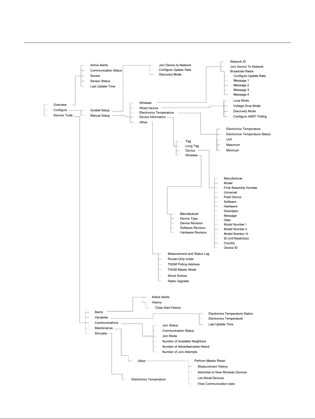
HART TREE
Smart Wireless THUM Adapter
2-5

Smart Wireless THUM Adapter
Reference Manual
00809-0100-4075, Rev BA
October 2010
2-6
 Loading...