

Manuals & Guides: Signal Converter With Liquid Sotware - Model 7951 | Micro Motion
Table of contents
 Loading...
Micro Motion Manuals & Guides: Signal Converter With Liquid Sotware - Model 7951 | Micro Motion Manuals & Guides

®
r
Operating Manual
MMI-20019473, Rev. AA
April 2011
7951 Signal Converter
(With Liquid Software 2010)
Klippon Connector Model
D-Type Connector Model
Micro Motion
7951 Signal Converte
Introduction
The Micro Motion
be used for single-stream density and viscosity
applications.
Software Version:
2010 – Liquid Density and Viscosity Applications.
Models Covered
7951MAA5*****
Models Covered
7951MAB5*****
:
®
7951 liquid signal converter can
:
:

IMPORTANT NOTICE
Because we are continuously improving our products, some of the menus which appear on
your instrument’s display may not be exactly as illustrated and described in this manual.
However, because the menus are simple and intuitive, this should not cause any major
problems.
This manual is concurrent with embedded software version 512010, issue 2.80.

Static precautions
Some parts of the instrument (such as circuit boards) may be damaged by static electricity.
Therefore, when carrying out any work which involves the risk of static damage to the instrument, the
instructions show the following notice:
CAUTION
At such times you must wear an earthed wrist-strap to protect the instrument.
While carrying out this procedure, you must wear an earthed wrist
strap at all times to protect the instrument against static shock.
Safety information
NOTE: This information applies only to those instruments which are mains-powered.
Electricity is dangerous and you risk injury or death if you do not disconnect the power supplies
before carrying out some of the procedures given in this manual. Whenever there is such a hazard,
the instructions show a notice similar to the following:
WARNING
You must heed any such warnings and make sure that, before you go any further:
Electricity is dangerous and can kill.
Disconnect all power supplies before proceeding.
• All power leads are un-powered.
• All power leads are disconnected from the equipment which you are working on
unless the instructions tell you otherwise.
• You obey any other common-sense precautions which may apply to your situation.
If you obey these sensible precautions, you can work on the equipment in complete safety.
Battery-backed Memory notice
• It is essential that the Lithium Cell used for the battery backup is installed at all times (other than
during replacement). The Micro Motion 7951 Signal Converter will not power-up correctly if this
battery is missing.
If it is necessary to run the units without batteries for Intrinsic Safety reasons, then the battery
should be replaced with a shorting disk inserted in the battery holder. Please consult the factory
for further advice.
• Replace the battery when the "Low Battery" system alarm is indicated. The procedure is
explained in Chapter 14.

Contents
1. About this manual 1.1
1.1 What this manual tells you 1.1
1.2 Who should use this manual 1.1
1.3 Software version covered by this manual 1.1
2. Getting started 2.1
2.1 What this chapter tells you 2.1
2.2 What the examples show you 2.1
2.3 If you need help… 2.1
2.4 Example 1: 7951 with a 7826/35/45/47 densitometer 2.2
2.5 Example 2: 7951 with a 7827 viscometer 2.5
2.6 Output Connections 2.8
2.6.1 Relay Ouput 2.8
2.6.2 Digital (Status) Outputs 2.8
3. About the Micro Motion® 7951 3.1
3.1 Background 3.1
3.2 What the 7951 Liquid Signal Converter does 3.1
3.3 Physical description of the 7951 3.2
3.4 Communications 3.3
3.5 Typical installations 3.4
3.6 Checking your software version 3.5
4. Installing the system 4.1
4.1 What this chapter tells you 4.1
4.2 Hazardous and non-hazardous environments 4.1
4.3 Installation procedure 4.1
4.4 Step 1: Drawing up a wiring schedule 4.1
4.5 Step 2: Unpacking the instrument 4.2
4.6 Step 3: Setting DIP switches 4.3
4.6.1 Analogue Input DIP-switches 4.3
4.6.2 Turbine voltage selection switch 4.3
4.7 Step 4: Fitting the 7951 4.4
4.8 Step 5: Making the external connections 4.6
4.9 Step 6: Earthing the instrument 4.6
4.10 Step 7: Connecting the power supply 4.8

5. The 7951 keyboard, display and indicators 5.1
5.1 What this chapter tells you 5.1
5.2 The layout of the front panel 5.1
5.3 What the display shows 5.2
5.4 How the buttons work 5.2
5.5 Using the buttons to move around the menus 5.2
5.6 Using the buttons to view stored data 5.3
5.7 Using the buttons to edit information 5.4
5.7.1 Text editing 5.4
5.7.2 Multiple-choice option selection 5.5
5.7.3 Numerical editing 5.5
5.7.4 Date and time editing 5.6
5.8 The 7951 character set 5.7
5.9 LED indicators 5.7
5.10 Summary of key functions 5.8
6. The menu system 6.1
6.1 What this chapter tells you 6.1
6.2 What the menu system does 6.1
6.3 How the menu system works 6.1
7. Serial Communications and Networking 7.1
7.1 What this chapter tells you 7.1
7.2 7951 Communication capabilities 7.1
7.3 MODBUS from the 7951 point of view 7.1
7.4 Connecting the 7951 to A MODBUS network 7.3
7.4.1 RS-232 connections 7.3
7.4.2 RS-485 (half duplex) connections 7.4
7.5 Configuring the 7951 to be a MODBUS slave 7.5
7.5.1 Port configuration 7.5
7.5.2 High speed list configuration 7.6
7.6 Database access over A MODBUS network 7.7
7.6.1 Introduction 7.7
7.6.2 Database information type 1 : Data values 7.8
7.6.3 Database information type 2 : Data states 7.9
7.6.4 Database information type 3 : Reply size and type 7.10
7.7 Alarm logger access over a MODBUS network 7.11
7.8 High speed list access over a MODBUS network
7.14
8. Alarms and Events 8.1
8.1 Alarms
8.1.1 Alarm types 8.1
8.1.2 Alarm indicators 8.1

8.1.3 How alarms are received and stored 8.2
8.1.4 Examining the Status Display and Historical Log 8.2
8.1.5 What the Status Display tells you 8.3
8.1.6 What the entries in the Historical Log tell you 8.3
8.1.7 Clearing all entries in the Historical Alarm Log 8.4
8.1.8 User-defined alarms X and Y 8.5
8.1.9 User-defined ‘comparison’ limit alarm 8.6
8.1.10 Alarm Logger Output (ALO) 8.7
8.1.11 Alarm Message List 8.8
8.2 Events 8.9
8.2.1 Introduction to 7951 events 8.9
8.2.2 Event indicators 8.9
8.2.3 How events are received and stored 8.9
8.2.4 Examining the Event Summary and the Event Log 8.10
8.2.5 What the Event Status Display tells you 8.10
8.2.6 What the entries in the Historical Event Log will tell you 8.11
8.2.7 Clearing all entries in the Historical Event Log 8.12
9. Additional facilities 9.1
9.1 What this chapter tells you 9.1
9.2 Averaging data 9.1
9.3 Selecting units and data formats 9.1
9.4 Limits 9.2
9.5 Fallback values and modes 9.2
9.6 Units which the 7951 can display 9.3
9.7 Automated calibration procedures 9.4
9.7.1 7827 Liquid Density Transducer 9.5
9.8 Feature: PID Control 9.6
9.8.1 Overview 9.6
9.8.2 Configuration details 9.7
9.8.3 Ramp-limit safeguard 9.9
9.8.4 Anti-Reset-Windup safeguard 9.10
10. Configuring with Wizards 10.1
10.1 Introduction to Wizards 10.1
10.2 Using Wizards 10.1
10.3 Quick-view Guide (Set-up Wizards) 10.3
10.4 Units Wizard Selection 10.4
11. Configuring without the Wizards 11.1
11.1 What does configuration involve? 11.1
11.2 Before you start 11.1
11.3 What will the sections tell you 11.2
11.4 Configuration Guide 11.3
11.5 Live Inputs 11.6
11.5.1 Analogue Inputs 11.6
11.5.2 Time Period Inputs 11.7

11.6 Temperature Channels (A to K) 11.8
11.7 Pressure 11.9
11.8 Density 11.10
11.8.1 Transducer measured density 11.10
11.8.2 4x5 Matrix referred density 11.12
11.8.3 API referred density 11.14
11.8.4 Specific gravity 11.16
11.8.5 Degrees Brix 11.16
11.8.6 Degrees Baumé 11.17
11.8.7 Percent Mass 11.17
11.8.8 Percent Volume 11.18
11.8.9 Degrees Twaddell 11.18
11.8.10 Degrees API 11.19
11.8.11 Special Equation Type 1 11.20
11.9 Viscosity 11.21
11.9.1 7827 measured viscosity 11.21
11.9.2 Kinematic viscosity measurement 11.23
11.9.3 4x5 Matrix reference viscosity 11.24
11.9.4 ASTM D341 reference viscosity 11.26
11.9.5 Multi-curve ASTM reference viscosity 11.28
11.9.6 Ignition indexes 11.30
11.9.7 Saybolt Universal Viscosity 11.31
11.9.8 Saybolt Furol Viscosity 11.32
11.9.9 Special Equation Type 4 11.33
11.10 Interface Detection (Density/Viscosity zoning) 11.34
11.11 Custom Applications 11.35
11.11.1 Special Equation Type 2 11.35
11.11.2 General Constants 11.35
11.12 Live outputs 11.36
11.12.1 Analogue Outputs 11.36
11.12.2 Information on Averaging and Filtering 11.37
11.13 Other Parameters 11.38
11.13.1 What the “Other parameters” option does 11.38
11.13.2 Passwords and security 11.39
11.13 Multiview 11.41
12. Routine operation (Data maps) 12.1
12.1 Viewing the data
12.2 Checking the performance of the 7951 12.3
12.3 Printed reports 12.5
12.4 Giving your 7951 a tag number 12.6
12.1
13. Routine maintenance and fault-finding 13.1
13.1 Cleaning the instrument 13.1
13.2 Fault-finding 13.1

14. Removal and replacement of parts 14.1
14.1 Front panel assembly 14.1
14.2 Display 14.1
14.3 Switch panel 14.2
14.4 Processor board 14.2
14.5 Power supply board 14.3
14.6 Connector board 14.3
14.7 Fuse 14.3
14.8 Back-up battery 14.4
14.9 Rear panel assembly 14.5
14.10 Mother board 14.6
15. Assembly drawing and parts list 15.1
15.1 What the drawing and parts list tells you 15.1
15.2 How to obtain spare parts 15.1
Appendices A.1
Appendix A Glossary A.1
Appendix B Blank wiring schedule B.1
Appendix C Technical data for the 7951 C.1
Appendix D Calculations and theory D.1

1. About this manual
1.1 What this manual tells you
This manual tells you how to install, configure, operate, and service the instrument. In addition, some information
is given to help you identify and correct some of the more common faults which may occur. However, since
repairs are done by changing suspected faulty assemblies, fault-finding to board component level is not covered.
This manual assumes that all devices or peripherals to be connected to the 795x have their own documentatio n
which tells you how to install and configure them. For this reason it is assumed that anything which you want to
link to the 795x is already installed and working correctly in accordance with the manufacturer’s instructions.
Since the instrument can be used for a wide variety of purposes, it is driven by software specially for your application.
This manual gives information about the so ftw are which applie s to y our machine only .
Throughout this manual the term '795x' is used to refer to all members of the 795x family (7950, 795 1, and 7955).
Chapter 1 About this manual
1.2 Who should use this manual
This manual is for anyone who installs, uses, services or repairs the 795x.
1.3 Software version covered by this manual
The software version dealt with in this manual is given on the title page. Chapter 3 tells you about the software is
installed in your instrument.
Page 1.1

Chapter 1 About this manual
Page 1.2

2. Getting started
2.1 What this chapter tells you
If you are new to the 7951, the worked examples in this chapter can help you to become familiar with the
installation and configuration procedures. The examples are:
• 7951 with a 7826, 7835, 7845, or 7847 liquid density transducer (see page 2.2).
• 7951 with a 7827 viscometer (see page 2.5).
Work through whichever one is most like your installation. Section 2.6 provides details of connections required
for the relay output and the digital (status) outputs.
2.2 What the examples show you
Each example shows you how to:
• Wire up a simple system in a non-hazardous area.
• Set the DIP-switches inside the 7951.
• Find the menu from which you start configuration.
• Clear the memory of details of any existing configuration (OPTIONAL).
• Select the appropriate wizard to configure the simple system.
• Work through the wizard and input information.
• View the results of your configuration.
The examples do not give full instructions on how to fit and configure installations. They are intended purely to
give you confidence to install and configure your own equipment. Chapter 4 tells you how to make permanent
installations.
Chapter 2 Getting started
2.3 If you need help...
If you get into difficulties...
If you get into difficulties when using the wizards, you can abandon the configuration and start again as follows:
1. From the menu, keep selecting NO (usually by pressing the c-button) or, if that option is not available:
2. Press the ENTER button until you can start selecting NO.
3. Carry on with (1) and (2) until you return to the wizard selection menu where you started.
4. Start the worked example again. The configuration you abandoned is cleared from the instrument’s
memory when you begin again.
If you don’t know where the buttons are...
Chapter 5 gives a full explanation of what all the buttons do.
Page 2.1

Chapter 2 Getting started
2.4 Example 1: 7951 with a 7826/35/45/47 densitometer
About this example
This example shows you how to connec t a 7826, 7835, 7845 , o r 7847 densitome ter to the 7951 , and then uses the
Liquid Density 1 wizard to configure the syste m . The 7951 can th en disp lay a density and temperature reading.
In this example, the Liquid Density 1 wizard configures the connections as follows:
• The densitometer is connected to the Time Period Input 1 terminals.
• The PRT is connected to Analogue Input 1 terminals.
Work through the example by following the instructions below. If you are not sure where the buttons are, refer to
Chapter 5.
Connect the
transducer
1. Wire the densitometer to the 7951 terminals, as in Figure 2.1 or Figure 2.2
2. To comply with EMC regulations, you must earth the 7951 to a suitable earth point.
7835/45/47
densitometer
7951
Klippon D-type
330R
PRT
+24V Power
+
1
2
-
3
4
5
Signal +ve
Signal -ve
0V Power
PRT Power +
PRT Signal +
PRT Signal -
PRT Power -
6
PL5/9
PL5/1
PL5/2
PL5/10
PL7/1
PL7/2
PL7/3
PL7/4
SK6/22
SK6/14
SK6/15
SK6/24
SK7/14
SK7/15
SK7/16
SK7/17
Figure 2.1: Wired connections for 7835, 7845, or 7847 with Standard Electronics
7826
(Frequency Output)
Densitometer
Supply +
Sig +
Supply -
+24V Power
Signal +ve
Signal -ve
0V Power
7951
Klippon D-type
PL5/9
PL5/1
PL5/2
PL5/10
SK6/22
SK6/14
SK6/15
SK6/24
Page 2.2
(PRT)
PRT Power +
PRT Signal +
PRT Signal -
PRT Power -
PL7/1
PL7/2
PL7/3
PL7/4
SK7/14
SK7/15
SK7/16
SK7/17
Figure 2.2: Wired connections for 7826 densitometer

Chapter 2 Getting started
Set DIP switches 3. Make sure that the DIP-switches are set as shown in Figure 2.3.
7951:
4-20mA
SW1
1
A
2
B
C
D
A
B
C
D
SW2
PRT
3
4
1
2
3
4
Figure 2.3: DIP-switch settings for Example 1
Turn on the power 4. Turn on the power to the system. The system goes through a Power-On-Self-Test
(POST) routine, which takes less than 30 seconds. When it is finished, ignore any
flashing alarm lights that may appear.
Go to the wizards
menu
5. Press the MENU button to go to Page 1 of the Main Menu (if you aren’t there already).
6. Press the DOWN-ARROW button to go to Page 2 of the menu.
7. Press the c-button to select “Configure”.
8. Press the a-button twice to go to the wizard selection menu.
Clear existing
configuration
(This is optional)
9. Press the b-button and then use the UP-ARROW or DOWN-ARROW button to scroll
through the option list until “Initialise” is shown.
10. Press the b-button to select “Initialise”.
11. Press the d-button to confirm that you want to lose the current configuration.
12. Wait a few seconds until “initialise” on display line 2 changes to “Select option”.
Select the wizard 13. Press the b-button then the UP-ARROW or DOWN-ARROW button to scroll through
the option list until “Liquid density 1” is shown.
14. Press the b-button to select “Liquid density 1”.
Start of wizard 15. Press the d-button to answer YES to the ‘Load Liquid density defaults?’ prompt.
Enter
densitometer
calibration factors
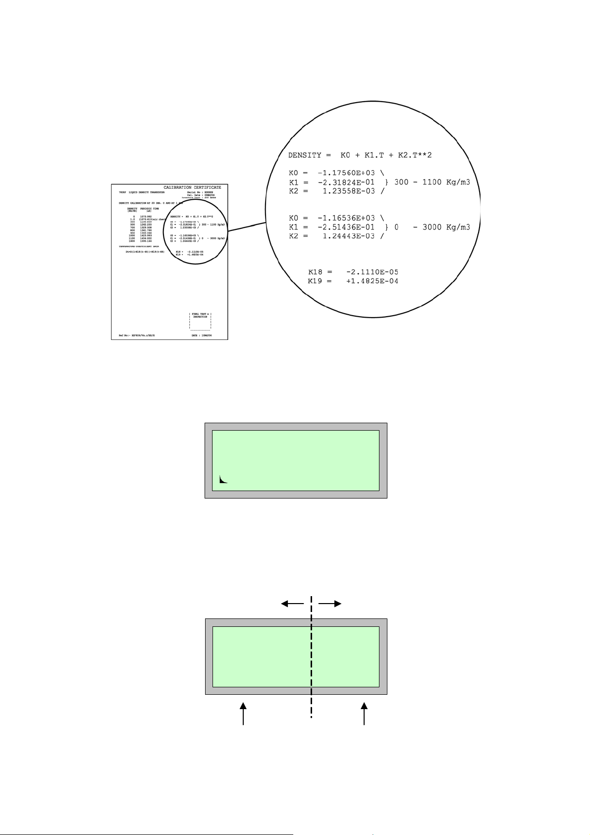
16. Press the d-button to answer YES to the ‘Edit density coefficients?’ prompt.
17. Press the b-button, then input the factor K0 from the Calibration Certificate for the
transducer. (See Figure 2.4 on page 2.4 for an illustration of the certificate).
18. Press the b-button followed by the ENTER button to confirm the K0 value.
19. Enter values for factors K1 and K2 in the same manner as factor K0.
Enter temperature
correction factors
20. Press the d-button to answer YES to the ‘Edit Liquid density correction?’ prompt.
21. Press ENTER button to keep the “Temperature” correction selected.
23. Enter values for factors K18 and K19 in the same manner as factor K0.
Skip questions 24. Use the c-button to answer NO to all further prompts until the Wizard is exited.
View how you
have configured
Line density
View the Multiview display
25. Press the MENU button.
26. Press the a-button twice. The display should now look similar to Figure 2.5, although
the values and text shown may vary.
27. Press the MULTI-VIEW DISPLAY button. The display looks similar to that in
Figure 2.6, although the text and values shown may vary.
End of Worked Example 1
Page 2.3
Chapter 2 Getting started
r
Figure 2.4: Where to obtain values for K0, K1, K18 and K19 from the Calibration Certificate
Line density
265.54
Kg/m3
Live
Figure 2.5: Line density display
Text width setting – a movable
boundary between text and value
Page 2.4
Line dens 685.05
Ref Dens 0.000
Temp 29.5
Press 0.00
Text (e.g. parameter names)
Figure 2.6: Multi-view display (after Liquid Density 1 wizard)
Value of paramete

2.5 Example 2: 7951 with a 7827 viscometer
About this example
This example shows you how to connect a 7827 viscometer to the 7951 and then us es the 7827 Density/Viscosity
wizard to configure the system. The 7951 can then display a viscosity, density and temperature reading.
In this example, the 7827 Density/Viscosity wizard configures the connections as follows:
• The viscometer is connected to Time Period Input 3 terminals.
• The PRT is connected to Analogue Input 1 terminals.
Work through the example by following the instructions below. If you are not sure where the buttons are, refer to
Chapter 5.
Connect the
transducer
1. Wire the 7827 viscometer to the 7951 terminals, as in Figure 2.7.
2. To comply with EMC regulations, you must earth the 7951 to a suitable earth point.
Chapter 2 Getting started
Set DIP
3. Make sure that the DIP-switches are set as shown in Figure 2.8.
switches
7827
viscometer
Supply +
Sig +
Supply -
(PRT)
+24V Power
Signal +ve
Signal -ve
0V Power
PRT Power +
PRT Signal +
PRT Signal -
PRT Power -
7951
Klippon D-type
PL5/9
PL5/5
PL5/6
PL5/10
PL7/1
PL7/2
PL7/3
PL7/4
SK6/23
SK6/18
SK6/25
SK6/19
SK7/14
SK7/15
SK7/16
SK7/17
Figure 2.7: Wired connections for 7827
7951:
4-20mA
SW1
A
B
C
D
1
2
PRT
3
4
SW2
1
2
3
4
A
B
C
D
Figure 2.8: Dip Switch settings for example 2
Page 2.5

Chapter 2 Getting started
Turn on the power 4. Turn on the power to the system. The system goes through a Power-On-Self-Test (POST)
routine, which takes less than 30 seconds. When it is finished, ignore any flashing alarm
lights that may appear.
Go to the wizards
menu
5. Press the MAIN MENU button to go to Page 1 of the Main Menu (if you aren’t there already).
6. Press the DOWN-ARROW button to go to Page 2 of the menu.
7. Press the c-button to select “Configure”.
8. Press the a-button twice to go to the wizard selection menu.
Clear existing
configuration
(This is optional)
9. Press the b-button and then use the UP-ARROW or DOWN-ARROW button to scroll
through the option list until “Initialise” is shown.
10. Press the b-button to select “Initialise”.
11. Press the d-button to confirm that you want to lose the current configuration.
12. Wait a few seconds until “initialise” on display line 2 changes to “Select option”.
Select the wizard 13. Press the b-button then the UP-ARROW or DOWN-ARROW button to scroll through the
option list until “7827 dens/visc” is shown.
14. Press the b-button to select “7827 dens/visc”.
Start of wizard 15. Press the d-button to answer YES to the ‘Load 7827 visco sity defaults?’ prompt.
Find out the
viscosity ranges
for which the 7827
16. The 7827 is calibrated for one or more of the viscosity ranges: High, Medium, Low or Ultra-
low. Check with the Calibration Certificate to see which ranges your instrument is
calibrated for. (See
Figure 2.9.)
is calibrated.
Select the ranges
for which your
transducer is
calibrated
solartron
S
S
7827ACALMT VISCOMETER SERIAL NO
VISCOSITY CALIBRATION @ nn C (T-piece)
DENSITY CALIBRATION @ nn C (T-piece)
VISCOSITY CORRECTION DATA
Dv = D t + (K20 + K21.1/Q**2 + K22.1/Q**4)
where
Ref No:- xxnnnn/Vn.n
O
VISCOSITY = V0 + V1.1/Q**2 + V2.1/Q**4
QUALITY
VISCOSITY
(cP)
FACTOR
INSTRUMENT CHECK DATA
nnn.nn
n
nnn.nn
nn
AIR POINT (nn C) QUALITY FACTOR
nn.nn
nnn
nn.nn
nnn
nn.nn
VISCOSITY CODE (for 7945V/6V) = nnnn
nnnn
nn.nn
nnnn
nn.nn
nnnnn
LOW RANGE
ULTRA-LOW RANGE
(n-nnn)
(n-nnn)
-n.nnnnnE+nn
-n.nnnnnE+nn
V0 =
n.nnnnnE+nn
n.nnnnnE+nn
V1 =
n.nnnnnE+nn
n.nnnnnE+nn
V2 =
O
TIME PERIOD B
DENSITY
3
(usec)
(Kg/m)
nnn.nnn
n
n.n
nnn.nnn air check
nnn.nnn
nnn
nnn.nnn
nnn
nnn.nnn
nnn
nnnn
nnn.nnn
nnn.nnn
nnnn
MEDIUM RANGE
K20 =
-n.nnnnnE+nn
n.nnnnnE+nn
K21 =
n.nnnnnE+nn
K22 =
D = Density (uncorrected)
Dt = Density (temperature corrected)
Dv = Density (temp and viscosity corrected)
TB = Time period B (uS)
Q = Quality Factor
o
t = Temperature ( C)
DENSITY = K0 + K1.TB + K2.TB**2
Dt = D( 1 + K18(t-20) ) + K19(t-20)
17. Press the d-button to answer YES to the question ‘Edit viscosity coefficient?’
18. Press the b-button, and then use the UP-ARROW button repeatedly until the display
shows the combination of viscosity ranges which applies to your 7827.
19. Press the b-button to select the option and then press the ENTER button to confirm that
you want to edit those viscosity ranges.
LOW RANGE
(n-nnn)
-n.nnnnnE+nn
n.nnnnnE+nn
n.nnnnnE+nn
-n.nnnnnE+nn
K0 =
K1 =
K2 =
K18 =
K19 =
n.nnnnnE-nn
n.nnnnnE-nn
-n.nnnE-nn
-n.nnnE+nn
MEDIUM RANGE
(nnn-nnnn)
-n.nnnnnE+nn
n.nnnnnE+nn
n.nnnnnE+nn
o
MEDIUM RANGE
(nnn-nnnn)
-n.nnnnnE+nn
n.nnnnnE+nn
n.nnnnnE+nn
K0 =
K1 =
K2 =
K18 =
K19 =
CAL DATE
PRESSURE TEST
-n.nnnnnE+nn
-n.nnnE-nn
-n.nnnE+nn
n.nnnnnE-nn
n.nnnnnE-nn
FINAL TEST &
INSPECTION
DATE : xxxxxxx
: nnnnnn
: xxxxxxx
:nnBAR
HIGH RANGE
(nnn-nnnnn)
n.nnnnnE+nn
n.nnnnnE+nn
n.nnnnnE+nn
ULTRA-LOW RANGE
(n-nnn)
-n.nnnnnE+nn
V0 =
n.nnnnnE+nn
V1 =
n.nnnnnE+nn
V2 =
= nnnn
DENSITY = K0 + K1.TB + K2.TB**2
Dt = D( 1 + K18(t-20) ) + K19(t-20)
HIGH RANGE
(nnn-nnnnn)
n.nnnnnE+nn
n.nnnnnE+nn
n.nnnnnE+nn
Page 2.6
Figure 2.9: Where to find values for V0, V1, V2, K0, K1, K2, K18 and K19 from the calibration certificate

r
Enter the
calibration factors
for each viscosity
range
Enter density
calibration factors
Enter temperature
correction factors
Skip over the next
few questions
View Line
Dynamic viscosity
View Multi-view
display
End of Worked Example 2
Chapter 2 Getting started
20. Repeat for each viscosity range (as selected in step 19):
• Press the b-button, and then input the factor V0 for the viscosity range.
• Press the b-button again, and then ENTER to confirm the details.
• Enter values for calibration factors V1 and V2 in the same manner as for V0.
• Press ENTER button to accept the default value (1.0) for the scale factor.
21. Press the d-button to answer YES to the ‘Edit Density coefficient?’ prompt.
22. Press the b-button then enter the value for factor K0 from the Calibration Certificate.
23. Press the b-button and then press the ENTER button to accept the K0 value.
24. Enter values for factors K1 and K2 in the same manner as for factor K0.
25. Press the d-button to answer YES to ‘Edit Liquid density correction?’ prompt.
26. Press ENTER button to keep the “temperature” correction selection.
27. Enter the value for factors K18 and K19 in the manner as for factor K0.
28. Press the c-button several times to answer NO to all questions until the wizard is exited
29. Press the MAIN MENU button.
30. Press the b-button and then the a-button. The display will look similar to that shown in
Figure 2.10, although the text and values shown may vary.
31. Press the MULTI-VIEW DISPLAY button. The display will look similar to that shown in
Figure 2.11, although the text and values shown may vary.
Line dyn visc
1000
cP
Live
Figure 2.10: Line Dynamic Viscosity display
Text width setting – a movable
boundary between text and value
Dyn.Visc 1000.00
Kin.Visc 0.000
Dens 0.00 0
Temp 29.5
Text (e.g. parameter names)
Figure 2.11: Multi-view display (after 7827 Density/Viscosity wizard)
Value of paramete
Page 2.7

Chapter 2 Getting started
2.6 Output Connections
2.6.1 Relay Output
There are 2 contacts:
1: “Normally Open” pin (D-type: SK4/12, Klippon: PL2/08) or
“Normally Closed” pin (D-type: SK4/25, Klippon: PL2/10)
2: “Common” pin (D-type: SK4/13, Klippon: PL2/9).
This output functions as a ‘Watchdog’ for indicating the presence of at least one active alarm. For example, the
Normally Open (NO) contact is energised only if there is an alarm.
2.6.2 Digital (Status) Outputs
These outputs are of the open-drain type. Work through parts 1, 2 and 3 to understand all the physical
connections that need to be made to the 7951:
1. Power usage - external power (recommended)
This diode protects 7951
against reverse voltages
7951
External power supply provides
voltage and current suitable for
user selected relay.
Status output
0V from external power supply
Status output common
Figure 2.12: Wiring a Status Output
2. Status Output “Common” Pin
7951 (D-Type) 7951 (Klippon) Comment
SK5/9 PL2/7 Use this pin for status outputs 2 to 4.
SK5/22
3. Status Output “Signal” Pin
-
Use this pin for status outputs 5 to 8.
Page 2.8
Status O/P Default Function
2 Limit Alarm Watchdog (ALO) SK5/1 PL2/1
3 Input Alarm Watchdog (ALO) SK5/2 PL2/2
Refer to Chapter 8 for information on alarm watchdog (ALO) function.
Status Outputs 4 to 8 are not used.
7951
(D-Type)
7951
(Klippon)

3. About the Micro Motion® 7951
3.1 Background
The Micro Motion® 7951 is designed to meet the demand for a reliable, versatile, user-friendly and cost-effective
instrument for liquid and gas metering. It has a Motorola 68332 32-bit microprocessor and surface-mounted
circuit board components so that it is powerful, reliable and compact.
Features of the 7951 include:
• Simple access to information.
• Comprehensive interrogation facilities.
• Alarm and alarm history facilities.
• A menu-driven, user-friendly interface.
• NEMA12, IP52 panel mounted case.
• Dc powered.
• Three serial ports (using RS232 or RS485) for
Modbus communications and printing.
These facilities are described in more detail in the rest of this chapter.
Chapter 3 About the Micro Motion® 7951
3.2 What the 7951 liquid signal converter does
Utilising field transmitters and transducers, the 7951 will calculate:
• Line density.
• Line dynamic viscosity.
• Line kinematic viscosity.
• Temperature (A to K).
• Line pressure.
From these values the 7951 can derive:
• Matrix temperature referred density, corrected for pressure.
• API referred density.
• Saybolt universal viscosity (ASTM D2161).
• Saybolt viscosity at 122 deg.F.
• Saybolt viscosity at 210 deg.F.
• Referred viscosity (ASTM D341 equation, multi-curve ASTM or 4x5 Matrix).
• Ignition indexes CAII and CII.
Additional features:
• Interface detection - density or viscosity zoning.
• PID Control.
• User defined equations (Types 1, 2 and 4).
• Multi-view Display key.
• Analogue Outputs.
• Security.
Page 3.1

Chapter 3 About the Micro Motion® 7951
3.3 Physical description of the 7951
The main body of the 7951 is a one-piece aluminium extrusion which provides the best possible EMC protection.
The keyboard and display is attached to the front of the instrument and all electrical and communications
connectors are mounted on the Rear Panel. The 7951 is available with two types of rear Panel - one with
Klippon connectors, the other with D-type connectors.
The case contains four circuit boards. The Processor Board and the Power Supply Board are mounted
horizontally. These are connected by plugs and sockets to the Mother Board which is mounted vertically at the
back of the case. The Connector Board is parallel to the Mother Board to which it is joined.
The Keyboard and Display are wired to the Processor Board. The Connector Board holds the connectors to
which external devices are linked.
Processor
Power
Supply
Board
Board
Two types of
Rear Panel
Either... Klippon connectors
SK1
SK2
SK3
PL3 PL4 PL5 PL6 PL7 PL8 PL9
PL2
PL1
D-type connectors
Or...
SK1
Connector
Board
Mother
SK2
SK3
Board
PL1
Keyboard
and display
Figure 3.1: The 7951 and its major assemblies
SK4 SK5 SK6 SK7 SK8
Page 3.2

3.4 Communications
The 7951 can operate as a MODBUS slave. It can:
• Download a configuration from a PC, DCS, etc.
• Upload a configuration.
• Monitor random locations in the 7951.
• Interrogate the alarm and data logger buffers.
• Manipulate the alarm and data logger buffers.
• Set random locations with new data.
• Instigate printed reports.
Chapter 7 in this manual gives full details on communications with the 7951 instrument.
Chapter 3 About the Micro Motion® 7951
Page 3.3

Chapter 3 About the Micro Motion® 7951
p
p
3.5 Typical installations
Figure 3.2 and Figure 3.3 illustrate two typical applications that are supported.
Part of pipeline
PT
DT
TE
4-wire PRT
Transducers and transmitters
Static pressure transducer
PT
DT
Density transmitter
Temperature element (PRT)
TE
7951
Alarm
Frequency
Analogue outputs
4-20mA
Printer
MODBUS communications
to and from host com
Figure 3.2: Liquid Density Application
uter
Part of pipeline
Page 3.4
V
DT
TE
4-wire PRT
Transducers and transmitters
Viscometer (Covimat or 7827 transducer)
V
DT
Density transmitter
Temperature element (PRT)
TE
Alarm
Frequency
Analogue outputs
Printer
4-20mA (from Covimat range)
OR Frequency (from a 7827)
MODBUS communications
to and from host com
Figure 3.3: A typical oil blending application
uter

3.6 Checking your software version
The 7951 is driven by pre-loaded software which differs according to the application for which the instrument is to
be used. To check hardware configuration, see Ordering Information in Appendix C.
PREFIX:
HARDWARE
PLATFORM
50 7950
51 7951
DIGIT 1:
METERED
PRODUCT
1 GAS
2 LIQU ID
3 BOTH
4 OTHER
PREFIX DIGIT 1 DIGIT 2 DIGIT 3 DIGIT 4
DIGIT 2:
FLOW
METER
0 NONE
1 ORIFIC E
2 TURBINE/PD
3 VENTURI
4 MASS
5 MULTI
Chapter 3 About the Micro Motion® 7951
DIGIT 3:
STREAMS/
CHANNELS
1 SINGLE
2 DUAL
3 TRIPLE
4 QUAD
5 1, 2, 3 or 4
DIGIT 4:
SPECIAL
0 – 9
SOFTWARE VERSION NUMBER
Figure 3.4: Software version number
Page 3.5

Chapter 3 About the Micro Motion® 7951
Page 3.6

4. Installing the system
4.1 What this chapter tells you
This chapter gives full instructions for installing the 7951.
It does not go into detail about how to install any peri phe ra l devices (such as transducers, computers or printers) which
are connected to the 7951. For this information you must re fer to the do cumen tation sup plied w ith th ese items.
4.2 Hazardous and non-hazardous environments
Caution:
Always refer to documentation supplied by the manufacturer for details of installing their equipment in a
hazardous area. The 7951 is neither intrinsically safe nor explosion-proof. and can therefore only
be used in a designated non-hazardous (safe) area.
If all or part of an installation is in an area where there is the risk of fire or explosion (which is almost always the
case when gases are involved), then safety barriers or galvanic isolators usually have to be wired into the
circuit. However, some instruments are explosion-proof and barriers are not, therefore, needed.
Chapter 4 Installing the system
4.3 Installation procedure
Briefly, the procedure is:
Step 1: Draw up a wiring schedule.
Step 2: Unpack the 7951.
Step 3: Set the DIP switches.
Step 4: Fit the 7951.
Step 5: Make all external connections.
Step 6: Earth the installation.
Step 7: Connect power supply.
The steps in the procedure are explained in the following sections.
4.4 Step 1: Drawing up a wiring schedule
Before you make any connections, you must draw up a wiring schedule to help you identify wiring colours and
make sure that you do not connect more items of any given type than are allowed. (If you are in doubt, check
the specification in Appendix C.)
A blank copy of a wiring schedule is given in Appendix B.
Page 4.1

Chapter 4 Installing the system
4.5 Step 2: Unpacking the instrument
Remove the instrument from its packing and examine it to see if any items are loose or if it has been damaged in
transit. Check that all items on the shipping list are present. If any items are missing or if the equipment is
damaged, contact your supplier immediately for further advice.
Note: If you have ordered an option card, this is already installed in the 7951.
Table 4.1: What should be supplied with the 7951 (Klippon)
Item Quantity
Mounting Clamp Assembly 1
Captive screws 2
Mounting strap 1
Location moulding 1
Socket identification label 1
9-way D-type plugs 3
9-way connector hoods 3
4-way socket 1
10-way sockets 8
2 Amp glass fuse (this is a spare) 1
Table 4.2: What should be supplied with the 7951 (D-type)
Item Quantity
Mounting Clamp Assembly 1
Captive screws 2
Mounting strap 1
Location moulding 1
9-way D-type plugs 3
9-way D-type connector hoods 3
25-way D-type plugs 5
25-way D-type connector hoods 5
4-way socket 1
2 Amp ceramic fuse (this is a spare) 1
Page 4.2

4.6 Step 3: Setting DIP-switches
Some types of connection may require DIP-switches to be set.
4.6.1 Analogue Input DP-switches
The 7951 has two blocks of DIP-switches on the Processor Board, as shown in Figure 4.1:
• SW1 switches
– select whether each input is 4-20 mA or PRT.
Chapter 4 Installing the system
• SW2 switches
– not used in the current version of 7951.
The setting of each switch in the SW2 block must be the same as the corresponding pair of switches in the
SW1 block. The 7951 may not work correctly otherwise.
The 7951 is supplied with the DIP-switches in these default settings:
• Input 1 PRT
• Inputs 2-4: 4-20mA
SW1
1
A
2
B
4-20mA
C
D
SW2
PRT
3
4
Part of the 7951
Processor Board
Figure 4.1: DIP-switches on the Processor Board
If you want to change the Analog Input switch settings, you must also configure the inputs. This is explained in
chapter 11. After the configuration has been completed, the 7951 should be switched into the 'secure' mode to
prevent unauthorised or accidental tampering with the instrument's configuration.
Note:
• The 7951 is always shipped from the factory with the security lock on the front panel set to the
‘non-secure’ mode.
4.6.2 Turbine Voltage Selection switches
The Turbine Voltage Selection switch is a DIP switch on the PSU Board, which is accessible through removal of
parts (see Chapter 14). Choose between 8 volts dc or 16 volts dc for all flow meters powered by the 7951.
The 7951 is shipped with the switch set for 8 volts dc.
For flow meter connection details, see chapter 2.
Page 4.3

Chapter 4 Installing the system
4.7 Step 4: Fitting the 7951
Caution:
You must not fit the 7951 where it may be subjected to extreme conditions or be liable to damage.
For further information about the environmental conditions within which it can operate, see
Appendix C.
1. Firstly, referring to Figure 4.4.2, cut out an aperture in the front panel for each instrument which is to be
mounted on it.
29±1mm
96±1mm
Aperture for the
instrument
Aperture for the
instrument
192±1mm
Aperture for the
instrument
Aperture for the
instrument
17.5mm
17±1mm
14.5mm
Figure 4.4.2: Minimum dimensions for a panel with apertures to fit four 7951’s
2. Each instrument is mounted in a clamp which is fixed to the rear of the front panel, as shown in the two
diagrams that follow.
The 7951 unit
101mm
278.7mm
Location
Moulding
3mm
Panel with
aperture
Mounting
Clamp
Figure 4.4.3: Before assembly
7.2mm
3mm
Captive
Clamp
Screws (2)
113mm
Mounting
Clamp
Rear Panel
of 7951
Page 4.4
12.5mm
256mm
10mm
Note: Sufficient clearance is required for plugs and cables at the rear of the 7951
221mm
Figure 4.4: After assembly

Chapter 4 Installing the system
p
You can mount the clamp so that it is fixed permanently or can be removed later, if required. If you want the clamp to
be fixed permanently, carry out Steps 3 - 8. If you want to be able to remove the clamp, carry out Steps 9 - 12.
If the clamp is to be fixed permanently:
1. Make sure that the face of the front panel is in good condition and has no loose or flaking paint. Use a
suitable de-greasing agent to clean the face of the panel.
2. Insert the location moulding through the aperture in the front panel.
3. Peel the protective strip off the adhesive tape on the face of the mounting clamp. Then, working from the
back of the front panel, carefully position the clamp over the location moulding. The clamp and pan el bond
on contact.
4. Press firmly on the area where the clamp is bonded to the front panel to ensure that they are bonded firmly.
Remove the Location Moulding and discard it.
5. Slide the instrument through the front panel. Tighten the two captive screws to secure it into the clamp.
6. Finally, attach all connectors to the back panel.
Note that, if you install more than one instrument, it helps to support them if you use a Mounting Strap to link
each clamp to the next one, as shown in Figure 4.5:
Back of
instrument
Mounting clamp Mounting clamp
Inside of
front panel
Mounting
stra
Back of
instrument
Figure 4.5: Mounting arrangements for more than one instrument
If the clamp is to be removable:
7. Insert the location moulding through the aperture in the front panel.
8. Working from the back of the front panel, carefully position the clamp over the location moulding. Remove the
Location Moulding and discard it.
9. Slide the instrument through the front panel. Tighten the two captive screws to secure it into the clamp.
Note that, if you install more than one instrument, it helps to support them if you use a Mounting Strap to link
each clamp to the next one, as shown in the diagram.
Page 4.5

Chapter 4 Installing the system
4.8 Step 5: Making the external connections
1. Refer to the documentation supplied with the external equipment to see if it is necessary to carry out any
special procedures when connecting them to the 7951. Take special notice of any information about safet y
requirements in hazardous areas, and complying with EMC regulations.
To meet the EC Directive for EMC (Electromagnetic Compatibility), it is recommended that the Flow Computer
be connected to transducers using a suitable instrumentation cable containing individually shielded twisted pairs
and an overall screen to cover all cores.
The instrumentation cables should have individual screen(s), foil or braid over each twisted pair and an
overall screen to cover all cores. Where permissible and depending on the earthing scheme employed at the
installation, the overall screen should be connected to the earthed metal work at both ends. (360° bonding
where possible). This may have multiple protective earth connections to the pipe work or the building
structure and not connected to the individual screen(s) or Instrumentation or Zener barrier grounds.
The individual inner screen(s) should be connected at one end only, normally the controller
(e.g. Flow Computer) end. These should be connected to the Instrumentation or Zener barrier ground.
Use suitable cables that meet BS5308 multi-pair Instrumentation Types 1 or 2.
2. For each D-type connector, pass the connector hood over the cable and wire up the connector. Secure the
hood and connector body together then connect the earth wire to the hood. Stick an identifying label on to
the connector hood.
3. For each Klippon connector, wire up the connector then stick an identifying label on it.
4. Check the wiring thoroughly against the schedule and wiring diagram.
5. Attach all connectors to the Rear Panel.
Refer to Chapter 2 and Appendix C for examples of field transmitter connections and a full list of the 7951’s pin identities.
4.9 Step 6: Earthing the instrument
Caution: Incorrect earthing can cause many problems, so you mu st earth the chassis and the
electronics correctly. The way in which you do this depends almost entirely on the type of
installation you have and the conditions under which it operates. Therefore, because these
instructions cannot cover every possible situation, the manufacturers recommend that
earthing procedures should only be carried out by personnel who are skilled in such work.
The chassis of the 7951 must be earthed in all cases; both for safety reasons and to ensure that the installation
complies with EMC regulations. Do this by connecting an earth lead from the stud on the rear panel (Figure 4.6) to
a local safety earth such as a cabinet earth or some other suitable metal structure. If there is more than one 7951,
see Figure 4.7 for correct and incorrect methods.
In addition to earthing the chassis, you may have to make extra earth connections in some cases, depending on
the installation requirements. Details of internal earthing arrangements are in Appendix C.
Crinkle
washers
Page 4.6
Nut
Earth
lead
Figure 4.6: The 7951’s Earth Stud
Plain
washers
Thumb
nut
Loading...