

Manuals & Guides: 2700 TRANSMITTER WITH ANALOG OUTPUTS CONFIGURATION AND USE MANUAL FOR CHINESE-LANGUAGE DISPLAY | Micro Motion
Table of contents
 Loading...
Micro Motion Manuals & Guides: 2700 TRANSMITTER WITH ANALOG OUTPUTS CONFIGURATION AND USE MANUAL FOR CHINESE-LANGUAGE DISPLAY | Micro Motion Manuals & Guides
Configuration and Use Manual
MMI-20021714, Rev AB
April
Micro Motion® Model 2700 Transmitters with
Analog Outputs
Includes the Chinese-Language Display Option
2013

Safety messages
Safety messages are provided throughout this manual to protect personnel and equipment. Read each safety message carefully
before proceeding to the next step.
Micro Motion customer service
Email
• Worldwide: flow.support@emerson.com
• Asia-Pacific: APflow.support@emerson.com
North and South America Europe and Middle East Asia Pacific
United States 800-522-6277 U.K. 0870 240 1978 Australia 800 158 727
Canada +1 303-527-5200 The Netherlands +31 (0) 318 495 555 New Zealand 099 128 804
Mexico +41 (0) 41 7686 111 France 0800 917 901 India 800 440 1468
Argentina +54 11 4837 7000 Germany 0800 182 5347 Pakistan 888 550 2682
Brazil +55 15 3238 3677 Italy 8008 77334 China +86 21 2892 9000
Venezuela +58 26 1731 3446 Central & Eastern +41 (0) 41 7686 111 Japan +81 3 5769 6803
Russia/CIS +7 495 981 9811 South Korea +82 2 3438 4600
Egypt 0800 000 0015 Singapore +65 6 777 8211
Oman 800 70101 Thailand 001 800 441 6426
Qatar 431 0044 Malaysia 800 814 008
Kuwait 663 299 01
South Africa 800 991 390
Saudia Arabia 800 844 9564
UAE 800 0444 0684

Contents
Contents
Part I Getting Started
Chapter 1 Before you begin ............................................................................................................. 3
1.1 About this manual .........................................................................................................................3
1.2 Transmitter model code ................................................................................................................3
1.3 Communications tools and protocols ............................................................................................3
1.4 Additional documentation and resources ......................................................................................4
Chapter 2 Quick start .......................................................................................................................7
2.1 Power up the transmitter ...............................................................................................................7
2.2 Check flowmeter status .................................................................................................................7
2.3 Make a startup connection to the transmitter ................................................................................9
2.4 Characterize the flowmeter (if required) ......................................................................................10
2.4.1 Sample sensor tags ....................................................................................................... 11
2.4.2 Flow calibration parameters (FCF, FT)
2.4.3 Density calibration parameters (D1, D2, K1, K2, FD, DT, TC) .............................................13
2.5 Verify mass flow measurement ....................................................................................................13
2.6 Verify the zero ............................................................................................................................. 14
2.6.1 Verify the zero using ProLink II ...................................................................................... 14
2.6.2 Verify the zero using ProLink III ..................................................................................... 15
2.6.3 Terminology used with zero verification and zero calibration ........................................16
........................................................................... 12
Part II Configuration and commissioning
Chapter 3 Introduction to configuration and commissioning ......................................................... 21
3.1 Configuration flowchart .............................................................................................................. 21
3.2 Default values and ranges ............................................................................................................23
3.3 Enable access to the off-line menu of the display ......................................................................... 23
3.4 Disable write-protection on the transmitter configuration .......................................................... 23
3.5 Restore the factory configuration ................................................................................................ 24
Chapter 4 Configure process measurement ................................................................................... 25
4.1 Configure mass flow measurement ............................................................................................. 25
4.1.1 Configure Mass Flow Measurement Unit ............................................................................. 25
4.1.2 Configure Flow Damping ..................................................................................................28
4.1.3 Configure Mass Flow Cutoff ..............................................................................................29
4.2 Configure volume flow measurement for liquid applications ....................................................... 31
4.2.1 Configure Volume Flow Type for liquid applications ..........................................................31
4.2.2 Configure Volume Flow Measurement Unit for liquid applications ........................................32
4.2.3 Configure Volume Flow Cutoff ...........................................................................................35
4.3 Configure gas standard volume (GSV) flow measurement ........................................................... 36
4.3.1 Configure Volume Flow Type for gas applications ............................................................. 37
4.3.2 Configure Standard Gas Density ........................................................................................37
4.3.3 Configure Gas Standard Volume Flow Measurement Unit ....................................................... 38
4.3.4 Configure Gas Standard Volume Flow Cutoff ....................................................................... 41
Configuration and Use Manual i

Contents
4.4 Configure Flow Direction .................................................................................................................
4.4.1 Options for Flow Direction ................................................................................................43
4.5 Configure density measurement ................................................................................................. 48
4.5.1 Configure Density Measurement Unit ..................................................................................49
4.5.2 Configure slug flow parameters .................................................................................... 50
4.5.3 Configure Density Damping .............................................................................................. 52
4.5.4 Configure Density Cutoff .................................................................................................. 53
4.6 Configure temperature measurement .........................................................................................54
4.6.1 Configure Temperature Measurement Unit .......................................................................... 54
4.6.2 Configure Temperature Damping .......................................................................................55
4.7 Configure the petroleum measurement application .................................................................... 56
4.7.1 Configure petroleum measurement using ProLink II ..................................................... 56
4.7.2 Configure petroleum measurement using ProLink III .................................................... 57
4.7.3 Configure petroleum measurement using the Field Communicator ..............................59
4.7.4 API reference tables ...................................................................................................... 60
4.8 Configure the concentration measurement application .............................................................. 61
4.8.1 Configure concentration measurement using ProLink II ................................................62
4.8.2 Configure concentration measurement using ProLink III ............................................... 64
4.8.3 Configure concentration measurement using the Field Communicator ........................ 67
4.8.4 Standard matrices for the concentration measurement application ..............................69
4.8.5 Derived variables and calculated process variables ........................................................70
4.9 Configure pressure compensation ...............................................................................................72
4.9.1 Configure pressure compensation using ProLink II ........................................................ 72
4.9.2 Configure pressure compensation using ProLink III ....................................................... 74
4.9.3 Configure pressure compensation using the Field Communicator ................................ 76
4.9.4 Options for Pressure Measurement Unit ..............................................................................77
43
Chapter 5 Configure device options and preferences ..................................................................... 79
5.1 Configure the transmitter display ................................................................................................ 79
5.1.1 Configure the language used for the display ................................................................. 79
5.1.2 Configure the process variables shown on the display ...................................................80
5.1.3 Configure the precision of variables shown on the display .............................................82
5.1.4 Configure the refresh rate of data shown on the display ................................................82
5.1.5 Enable or disable automatic scrolling through the display variables .............................. 83
5.1.6 Enable or disable the display backlight ..........................................................................84
5.1.7 Enable or disable Status LED Blinking ................................................................................84
5.2 Enable or disable operator actions from the display ..................................................................... 85
5.2.1 Enable or disable Totalizer Start/Stop from the display ..................................................85
5.2.2 Enable or disable Totalizer Reset from the display ......................................................... 86
5.2.3 Enable or disable the Acknowledge All Alarms display command .................................. 87
5.3 Configure security for the display menus .................................................................................... 87
5.4 Configure response time parameters .......................................................................................... 89
5.4.1 Configure Update Rate .................................................................................................... 89
5.4.2 Configure Calculation Speed (Response Time) .................................................................... 91
5.5 Configure alarm handling ............................................................................................................ 92
5.5.1 Configure Fault Timeout ...................................................................................................92
5.5.2 Configure Status Alarm Severity ........................................................................................ 93
5.6 Configure informational parameters ........................................................................................... 97
5.6.1 Configure Descriptor ....................................................................................................... 97
5.6.2 Configure Message .........................................................................................................98
5.6.3 Configure Date ...............................................................................................................98
5.6.4 Configure Sensor Serial Number ....................................................................................... 99
ii Micro Motion® Model 2700 Transmitters with Analog Outputs

Contents
5.6.5 Configure Sensor Material ................................................................................................
5.6.6 Configure Sensor Liner Material ...................................................................................... 100
5.6.7 Configure Sensor Flange Type ........................................................................................100
99
Chapter 6 Integrate the meter with the control system ................................................................103
6.1 Configure the transmitter channels ........................................................................................... 103
6.2 Configure the mA output .......................................................................................................... 104
6.2.1 Configure mA Output Process Variable ............................................................................. 104
6.2.2 Configure Lower Range Value (LRV) and Upper Range Value (URV) ....................................106
6.2.3 Configure AO Cutoff ......................................................................................................108
6.2.4 Configure Added Damping ............................................................................................. 110
6.2.5 Configure mA Output Fault Action and mA Output Fault Level ...............................................111
6.3 Configure the frequency output ................................................................................................ 112
6.3.1 Configure Frequency Output Process Variable ................................................................... 113
6.3.2 Configure Frequency Output Polarity ................................................................................ 114
6.3.3 Configure Frequency Output Scaling Method ..................................................................... 115
6.3.4 Configure Frequency Output Maximum Pulse Width ............................................................ 117
6.3.5 Configure Frequency Output Fault Action and Frequency Output Fault Level ........................... 118
6.4 Configure the discrete output ................................................................................................... 119
6.4.1 Configure Discrete Output Source ....................................................................................120
6.4.2 Configure Discrete Output Polarity ................................................................................... 122
6.4.3 Configure Discrete Output Fault Action ............................................................................. 124
6.5 Configure events ....................................................................................................................... 125
6.5.1 Configure a basic event ...............................................................................................125
6.5.2 Configure an enhanced event ..................................................................................... 126
6.6 Configure digital communications ............................................................................................ 128
6.6.1 Configure HART/Bell 202 communications ................................................................. 129
6.6.2 Configure HART/RS-485 communications .................................................................. 134
6.6.3 Configure Modbus/RS-485 communications .............................................................. 135
6.6.4 Configure Digital Communications Fault Action ...................................................................137
Chapter 7 Completing the configuration ......................................................................................139
7.1 Test or tune the system using sensor simulation ........................................................................139
7.1.1 Sensor simulation ....................................................................................................... 140
7.2 Back up transmitter configuration ............................................................................................. 141
7.3 Enable write-protection on the transmitter configuration ......................................................... 142
Chapter 8 Set up the Weights & Measures application ................................................................. 143
8.1 Weights & Measures application ................................................................................................143
8.2 Set up the Weights & Measures application using ProLink II ....................................................... 144
8.3 Set up the Weights & Measures application using ProLink III ...................................................... 147
Part III Operations, maintenance, and troubleshooting
Chapter 9 Transmitter operation ................................................................................................. 153
9.1 Record the process variables ..................................................................................................... 153
9.2 View process variables ...............................................................................................................154
9.2.1 View process variables using the display (standard option) ......................................... 154
9.2.2 View process variables using the Chinese-language display ........................................ 155
9.2.3 View process variables using ProLink III ....................................................................... 156
9.3 View transmitter status using the status LED ............................................................................. 156
9.4 View and acknowledge status alarms ........................................................................................ 157
Configuration and Use Manual iii

Contents
9.4.1 View and acknowledge alarms using the display (standard option) .............................157
9.4.2 View and acknowledge alarms using the Chinese-language display ............................ 160
9.4.3 View and acknowledge alarms using ProLink II ............................................................162
9.4.4 View and acknowledge alerts using ProLink III .............................................................162
9.4.5 View alarms using the Field Communicator ................................................................ 163
9.4.6 Alarm data in transmitter memory ..............................................................................163
9.5 Read totalizer and inventory values ........................................................................................... 164
9.6 Start and stop totalizers and inventories ....................................................................................165
9.6.1 Start and stop totalizers and inventories using the display (standard option) .............. 165
9.7 Reset totalizers ..........................................................................................................................166
9.7.1 Reset totalizers using the display (standard option) .................................................... 167
9.8 Reset inventories ....................................................................................................................... 168
Chapter 10 Operate the transmitter with the Weights & Measures application .............................. 169
10.1 Operate the transmitter when the Weights & Measures application is installed ......................... 169
10.1.1 Approved methods to read or obtain process data ......................................................170
10.1.2 Large totalizer values on the display (OIML applications only) ..................................... 170
10.1.3 Effect of the Weights & Measures application on process measurement and
outputs
10.1.4 Effect of the Weights & Measures application on operation and maintenance
functions .................................................................................................................... 172
10.2 Switch between secured and unsecured mode .......................................................................... 174
10.2.1 Switch between secured and unsecured mode using ProLink II ................................... 175
10.2.2 Switch between secured and unsecured mode using ProLink III .................................. 175
10.2.3 Switch between secured and unsecured mode using the switching utility ...................176
10.3 Clear Status Alarm A027: Security Breach .................................................................................. 176
10.4 Replacing the core processor in a Weights & Measures installation ............................................ 177
.......................................................................................................................171
Chapter 11 Measurement support ................................................................................................. 179
11.1 Options for measurement support ............................................................................................ 179
11.2 Use Smart Meter Verification .....................................................................................................179
11.2.1 Smart Meter Verification requirements .......................................................................180
11.2.2 Smart Meter Verification test preparation ...................................................................180
11.2.3 Run Smart Meter Verification ......................................................................................181
11.2.4 View test data .............................................................................................................187
11.2.5 Schedule automatic execution of the Smart Meter Verification test ............................193
11.3 Zero the flowmeter ................................................................................................................... 198
11.3.1 Zero the flowmeter using the display (standard option) ..............................................199
11.3.2 Zero the flowmeter using the Chinese-language display ............................................. 200
11.3.3 Zero the flowmeter using ProLink II .............................................................................201
11.3.4 Zero the flowmeter using ProLink III ............................................................................202
11.3.5 Zero the flowmeter using the Field Communicator ..................................................... 203
11.4 Validate the meter .....................................................................................................................205
11.4.1 Alternate method for calculating the meter factor for volume flow .............................206
11.5 Perform a (standard) D1 and D2 density calibration ...................................................................207
11.5.1 Perform a D1 and D2 density calibration using ProLink II ............................................. 207
11.5.2 Perform a D1 and D2 density calibration using ProLink III ............................................ 209
11.5.3 Perform a D1 and D2 density calibration using the Field Communicator ..................... 210
11.6 Perform a D3 and D4 density calibration (T-Series sensors only) ................................................ 212
11.6.1 Perform a D3 or D3 and D4 density calibration using ProLink II ....................................212
11.6.2 Perform a D3 or D3 and D4 density calibration using ProLink III ...................................213
11.6.3 Perform a D3 or D3 and D4 density calibration using the Field Communicator ............214
11.7 Perform temperature calibration ............................................................................................... 216
iv Micro Motion® Model 2700 Transmitters with Analog Outputs

Contents
11.7.1 Perform temperature calibration using ProLink II ........................................................ 216
11.7.2 Perform temperature calibration using ProLink III ....................................................... 217
Chapter 12 Troubleshooting .......................................................................................................... 219
12.1 Status LED states ....................................................................................................................... 220
12.2 Status alarms .............................................................................................................................220
12.3 Flow measurement problems .................................................................................................... 232
12.4 Density measurement problems ............................................................................................... 234
12.5 Temperature measurement problems .......................................................................................235
12.6 Milliamp output problems ......................................................................................................... 236
12.7 Frequency output problems ...................................................................................................... 237
12.8 Use sensor simulation for troubleshooting ................................................................................ 238
12.9 Check power supply wiring ........................................................................................................ 238
12.10 Check sensor-to-transmitter wiring ........................................................................................... 239
12.11 Check grounding ....................................................................................................................... 239
12.12 Perform loop tests ..................................................................................................................... 240
12.12.1 Perform loop tests using the display (standard option) ............................................... 240
12.12.2 Perform loop tests using the Chinese-language display ...............................................241
12.12.3 Perform loop tests using ProLink II .............................................................................. 243
12.12.4 Perform loop tests using ProLink III ............................................................................. 244
12.12.5 Perform loop tests using the Field Communicator ...................................................... 246
12.13 Trim mA outputs ....................................................................................................................... 247
12.13.1 Trim mA outputs using ProLink II ................................................................................ 247
12.13.2 Trim mA outputs using ProLink III ................................................................................248
12.13.3 Trim mA outputs using the Field Communicator .........................................................249
12.14 Check the HART communication loop ....................................................................................... 249
12.15 Check HART Address and Loop Current Mode ..................................................................................
12.16 Check HART burst mode ............................................................................................................250
12.17 Check Lower Range Value and Upper Range Value ........................................................................... 251
12.18 Check mA Output Fault Action ........................................................................................................ 251
12.19 Check for radio frequency interference (RFI) .............................................................................. 251
12.20 Check Frequency Output Maximum Pulse Width ................................................................................. 251
12.21 Check Frequency Output Scaling Method .......................................................................................... 252
12.22 Check Frequency Output Fault Action ............................................................................................... 252
12.23 Check Flow Direction .................................................................................................................... 252
12.24 Check the cutoffs ...................................................................................................................... 252
12.25 Check for slug flow (two-phase flow) ......................................................................................... 253
12.26 Check the drive gain .................................................................................................................. 253
12.26.1 Collect drive gain data ................................................................................................ 255
12.27 Check the pickoff voltage .......................................................................................................... 255
12.27.1 Collect pickoff voltage data ........................................................................................ 256
12.28 Check for electrical shorts ..........................................................................................................256
12.28.1 Check the sensor coils .................................................................................................256
12.29 Check the core processor LED ....................................................................................................258
12.29.1 Core processor LED states ........................................................................................... 260
12.30 Perform a core processor resistance test ................................................................................... 262
250
Appendices and reference
Appendix A Using the standard transmitter display ........................................................................ 265
A.1 Components of the transmitter interface .................................................................................. 265
A.2 Use the optical switches ............................................................................................................ 266
Configuration and Use Manual v

Contents
A.3 Access and use the display menu system ...................................................................................267
A.3.1 Enter a floating-point value using the display .............................................................. 268
A.4 Display codes for process variables ............................................................................................271
A.5 Codes and abbreviations used in display menus ........................................................................ 272
A.6 Menu maps for the transmitter display ...................................................................................... 276
Appendix B Using the Chinese-language display ............................................................................. 287
B.1 Components of the transmitter interface .................................................................................. 287
B.2 Use the optical switches ............................................................................................................ 288
B.3 Access and use the display menu system ................................................................................... 289
B.3.1 Enter a floating-point value using the display .............................................................. 290
B.4 Menu maps for the transmitter display ...................................................................................... 294
Appendix C Using ProLink II with the transmitter ........................................................................... 307
C.1 Basic information about ProLink II ..............................................................................................307
C.2 Connect with ProLink II ..............................................................................................................308
C.2.1 ProLink II connection types ......................................................................................... 308
C.2.2 Make a service port connection ...................................................................................309
C.2.3 Make a HART/Bell 202 connection .............................................................................. 310
C.2.4 Make a HART/RS-485 connection ................................................................................315
C.2.5 Make a Modbus/RS-485 connection ............................................................................318
C.3 Menu maps for ProLink II ........................................................................................................... 321
Appendix D Using ProLink III with the transmitter ...........................................................................331
D.1 Basic information about ProLink III .............................................................................................331
D.2 Connect with ProLink III ............................................................................................................. 332
D.2.1 ProLink III connection types ........................................................................................ 332
D.2.2 Make a service port connection ...................................................................................333
D.2.3 Make a HART/Bell 202 connection .............................................................................. 334
D.2.4 Make a HART/RS-485 connection ................................................................................339
D.2.5 Make a Modbus/RS-485 connection ............................................................................342
D.3 Menu maps for ProLink III .......................................................................................................... 345
Appendix E Using the Field Communicator with the transmitter .....................................................355
E.1 Basic information about the Field Communicator ......................................................................355
E.2 Connect with the Field Communicator ...................................................................................... 356
E.3 Menu maps for the Field Communicator ....................................................................................359
Appendix F Default values and ranges ............................................................................................ 375
F.1 Default values and ranges ..........................................................................................................375
Appendix G Transmitter components and installation wiring ......................................................... 381
G.1 Installation types ....................................................................................................................... 381
G.2 Power supply terminals and ground ...........................................................................................385
G.3 Input/output (I/O) wiring terminals ........................................................................................... 386
Appendix H NE 53 history ............................................................................................................... 387
H.1 NE 53 history ............................................................................................................................. 387
Index ................................................................................................................................................393
vi Micro Motion® Model 2700 Transmitters with Analog Outputs

Part I
Getting Started
Chapters covered in this part:
• Before you begin
• Quick start
Getting Started
Configuration and Use Manual 1

Getting Started
2 Micro Motion® Model 2700 Transmitters with Analog Outputs

1 Before you begin
Topics covered in this chapter:
• About this manual
• Transmitter model code
• Communications tools and protocols
• Additional documentation and resources
1.1 About this manual
This manual provides information to help you configure, commission, use, maintain, and
troubleshoot the Micro Motion transmitter.
Important
This manual assumes that the transmitter has been installed correctly and completely, according to
the instructions in the transmitter installation manual, and that the installation complies with all
applicable safety requirements.
Before you begin
1.2 Transmitter model code
Your transmitter can be identified by the model number on the transmitter tag.
The transmitter has a model number of the following form:
2700(I/R/C/B)**A******
I Integral mount
R 4-wire remote-mount
C 9-wire remote-mount
B Remote core processor with remote transmitter
A Analog outputs option board
1.3 Communications tools and protocols
You can use several different communications tools and protocols to interface with the
transmitter. You may use different tools in different locations or for different tasks.
Configuration and Use Manual 3

Before you begin
Communications tools, protocols, and related informationTable 1-1:
Communications tool Supported protocols Scope In this manual For more information
Display (standard)
Chinese-language display
ProLink II • HART/RS-485
ProLink III • HART/RS-485
Field Communicator
Not applicable Basic configuration and
commissioning
Not applicable Basic configuration and
commissioning
(1)
• HART/Bell 202
• Modbus/RS-485
• Service port
(1)
• HART/Bell 202
• Modbus/RS-485
• Service port
HART/Bell 202 Complete configuration
Complete configuration
and commissioning
Complete configuration
and commissioning
and commissioning
Complete user information. See Appendix A.
Complete user information. See Appendix B.
Basic user information.
See Appendix C.
Basic user information.
See Appendix D.
Basic user information.
See Appendix E.
Not applicable
Not applicable
User manual
• Installed with soft-
ware
• On Micro Motion
user documentation
CD
• On Micro Motion
web site (www.mi-
cromotion.com
User manual
• Installed with soft-
ware
• On Micro Motion
user documentation
CD
• On Micro Motion
web site (www.mi-
cromotion.com
User manual on
Micro Motion web site
(www.micromo-
tion.com
Tip
You may be able to use other communications tools from Emerson Process Management, such as
AMS Suite: Intelligent Device Manager, or the Smart Wireless THUM™ Adapter. Use of AMS or the
Smart Wireless THUM Adapter is not discussed in this manual. The AMS interface is similar to the
ProLink II interface. For more information on the Smart Wireless THUM Adapter, refer to the
documentation available at www.micromotion.com.
1.4 Additional documentation and resources
Micro Motion provides additional documentation to support the installation and operation
of the transmitter.
(1) Devices with the Chinese-language display do not support HART/RS-485.
4 Micro Motion® Model 2700 Transmitters with Analog Outputs

Before you begin
Additional documentation and resourcesTable 1-2:
Topic Document
Sensor Sensor documentation
Transmitter installation
Hazardous area installation See the approval documentation shipped with the transmitter, or
download the appropriate documentation from the Micro Motion
web site at www.micromotion.com.
All documentation resources are available on the Micro Motion web site at
www.micromotion.com or on the Micro Motion user documentation CD.
Configuration and Use Manual 5

Before you begin
6 Micro Motion® Model 2700 Transmitters with Analog Outputs

2 Quick start
Topics covered in this chapter:
• Power up the transmitter
• Check flowmeter status
• Make a startup connection to the transmitter
• Characterize the flowmeter (if required)
• Verify mass flow measurement
• Verify the zero
2.1 Power up the transmitter
The transmitter must be powered up for all configuration and commissioning tasks, or for
process measurement.
Ensure that all transmitter and sensor covers and seals are closed.
1.
Quick start
CAUTION!
To prevent ignition of flammable or combustible atmospheres, ensure that all covers
and seals are tightly closed. For hazardous area installations, applying power while
housing covers are removed or loose can cause an explosion.
2. Turn on the electrical power at the power supply.
The transmitter will automatically perform diagnostic routines. During this period,
Alarm 009 is active. The diagnostic routines should complete in approximately
30 seconds. For transmitters with a display, the status LED will turn green and begin
to flash when the startup diagnostics are complete. If the status LED exhibits
different behavior, an alarm condition is present.
Postrequisites
Although the sensor is ready to receive process fluid shortly after power-up, the electronics
can take up to 10 minutes to reach thermal equilibrium. Therefore, if this is the initial
startup, or if power is been off long enough to allow components to reach ambient
temperature, allow the electronics to warm up for approximately 10 minutes before
relying on process measurements. During this warm-up period, you may observe minor
measurement instability or inaccuracy.
2.2 Check flowmeter status
Check the flowmeter for any error conditions that require user action or that affect
measurement accuracy.
Configuration and Use Manual 7

Quick start
1. Wait approximately 10 seconds for the power-up sequence to complete.
Immediately after power-up, the transmitter runs through diagnostic routines and
checks for error conditions. During the power-up sequence, Alarm A009 is active.
This alarm should clear automatically when the power-up sequence is complete.
2.
Check the status LED on the transmitter.
Transmitter status reported by status LEDTable 2-1:
LED state Description Recommendation
Green No alarms are active. Continue with configuration or process meas-
urement.
(3)
(1)
(2)
No alarms are active. One or more previously
active alarms have not been acknowledged.
and have been acknowledged.
One or more low-severity alarms are active
and have not been acknowledged.
and have been acknowledged.
One or more high-severity alarms are active
and have not been acknowledged.
Continue with configuration or process measurement. If you choose, you can acknowledge
the alarms.
A low-severity alarm condition does not affect
measurement accuracy or output behavior.
You can continue with configuration or process measurement. If you choose, you can identify and resolve the alarm condition.
A low-severity alarm condition does not affect
measurement accuracy or output behavior.
You can continue with configuration or process measurement. If you choose, you can identify and resolve the alarm condition. You may
also acknowledge the alarm.
A high-severity alarm condition affects measurement accuracy and output behavior. Resolve the alarm condition before continuing.
A high-severity alarm condition affects measurement accuracy and output behavior. Resolve the alarm condition before continuing.
You may also acknowledge the alarm.
Flashing green
Yellow One or more low-severity alarms are active,
Flashing yellow
Red One or more high-severity alarms are active,
Flashing red
Postrequisites
For information on viewing the list of active alarms, see Section 9.4.
For information on individual alarms and suggested resolutions, see Section 12.2.
(1) If Status LED Blinking is disabled, the LED will show solid green rather than flashing.
(2)
If Status LED Blinking is disabled, the LED will show solid yellow rather than flashing.
(3) If Status LED Blinking is disabled, the LED will show solid red rather than flashing.
8 Micro Motion® Model 2700 Transmitters with Analog Outputs

Quick start
2.3 Make a startup connection to the transmitter
For all configuration tools except the display, you must have an active connection to the
transmitter to configure the transmitter. Follow this procedure to make your first
connection to the transmitter.
Identify the connection type to use, and follow the instructions for that connection type in
the appropriate appendix. Use the default communications parameters shown in the
appendix.
Communications tool Connection type to use Instructions
ProLink II HART/RS-485
ProLink III HART/RS-485
Field Communicator HART Appendix E
Postrequisites
(Optional) Change the communications parameters to site-specific values.
(4)
(4)
Appendix C
Appendix D
To change the communications parameters using ProLink II:
• To change the protocol, baud rate, parity, or stop bits, choose ProLink > Configuration >
RS-485.
• To change the address, choose ProLink > Configuration > Device.
To change the communications parameters using ProLink III, choose Device Tools >
Configuration > Communications.
To change the communications parameters using the Field Communicator, choose On-Line
Menu > Configure > Manual Setup > Inputs/Outputs > Communications.
Important
If you are changing communications parameters for the connection type that you are using, you will
lose the connection when you write the parameters to the transmitter. Reconnect using the new
parameters.
(4) Devices with the Chinese-language display do not support HART/RS-485. The default connection to use for these devices is Modbus/RS-485.
Configuration and Use Manual 9

Quick start
2.4 Characterize the flowmeter (if required)
Display (standard) Not available
Chinese-language
display
ProLink II • ProLink > Configuration > Device > Sensor Type
ProLink III Device Tools > Calibration Data
Field Communicator Configure > Manual Setup > Characterize
Overview
Characterizing the flowmeter adjusts your transmitter to match the unique traits of the
sensor it is paired with. The characterization parameters (also called calibration
parameters) describe the sensor’s sensitivity to flow, density, and temperature.
Depending on your sensor type, different parameters are required. Values for your sensor
are provided by Micro Motion on the sensor tag or the calibration certificate.
Offline Maintain > Configuration > Calibrate Sensor
• ProLink > Configuration > Flow
• ProLink > Configuration > Density
• ProLink > Configuration > T Series
Tip
If your flowmeter was ordered as a unit, it has already been characterized at the factory. However,
you should still verify the characterization parameters.
Procedure
1.
Specify Sensor Type.
• Straight-tube (T-Series)
(5)
• Curved-tube (all sensors except T-Series)
2. Set the flow characterization parameters. Be sure to include all decimal points.
• For straight-tube sensors, set FCF (Flow Cal or Flow Calibration Factor), FTG, and
(5)
FFQ.
• For curved-tube sensors, set Flow Cal (Flow Calibration Factor).
3. Set the density characterization parameters.
• For straight-tube sensors, set D1, D2, DT, DTG, K1, K2, FD, DFQ1, and DFQ2.
(5)
• For curved-tube sensors, set D1, D2, TC, K1, K2, and FD. (TC is sometimes shown
as DT.)
(5) Devices with the Chinese-language display do not support T-Series sensors.
10 Micro Motion® Model 2700 Transmitters with Analog Outputs

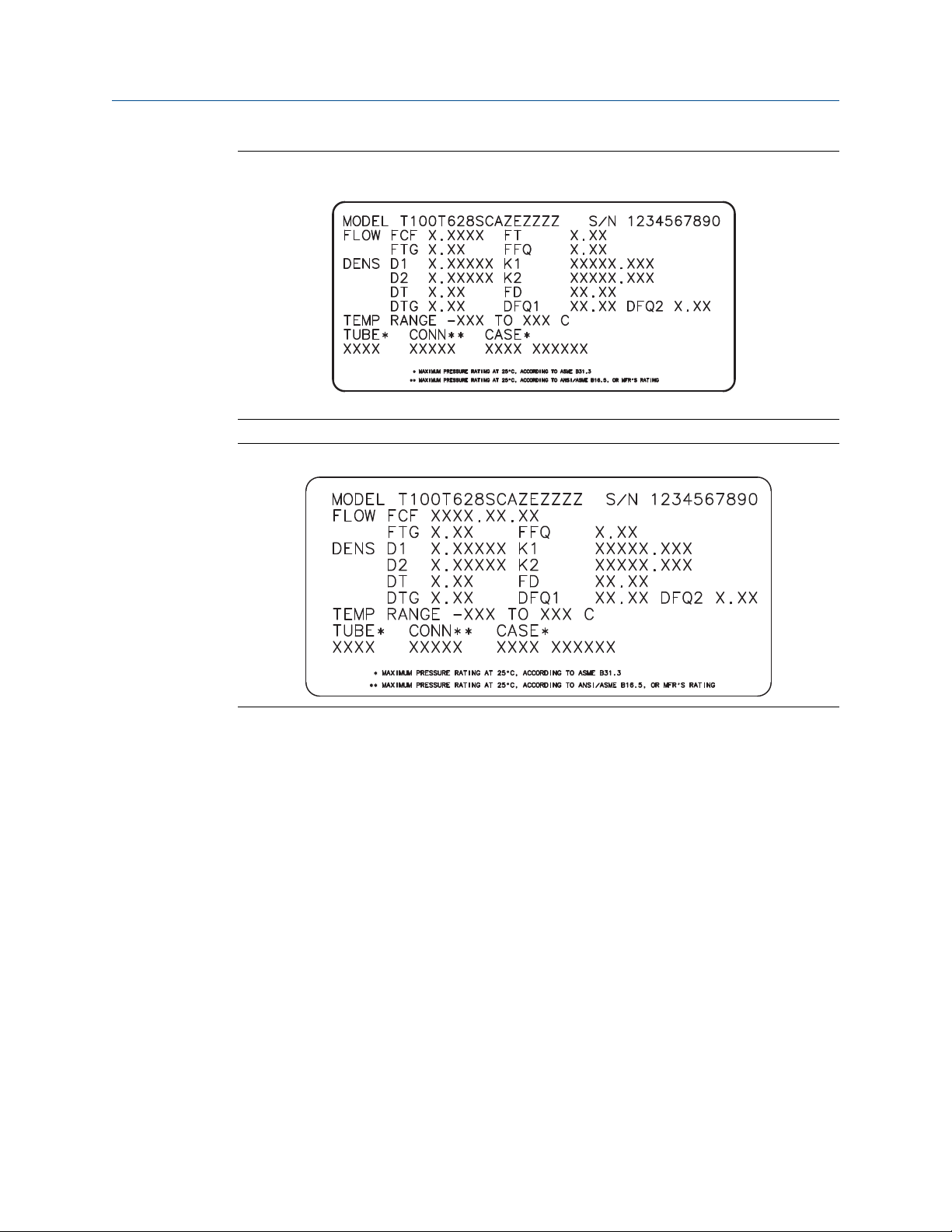
2.4.1 Sample sensor tags
Tag on older curved-tube sensors (all sensors except T-Series)Figure 2-1:
Quick start
Tag on newer curved-tube sensors (all sensors except T-Series)Figure 2-2:
Configuration and Use Manual 11
Quick start
Tag on older straight-tube sensor (T-Series)Figure 2-3:
Tag on newer straight-tube sensor (T-Series)Figure 2-4:
2.4.2 Flow calibration parameters (FCF, FT)
Two separate values are used to describe flow calibration: a 6-character FCF value and a 4character FT value. They are provided on the sensor tag.
Both values contain decimal points. During characterization, these may be entered as two
values or as a single 10-character string. The 10-character string is called either Flowcal or
FCF.
If your sensor tag shows the FCF and the FT values separately and you need to enter a
single value, concatenate the two values to form the single parameter value.
If your sensor tag shows a concatenated Flowcal or FCF value and you need to enter the FCF
and the FT values separately, split the concatenated value:
• FCF = The first 6 characters, including the decimal point
• FT = The last 4 characters, including the decimal point
12 Micro Motion® Model 2700 Transmitters with Analog Outputs

Quick start
Example: Concatenating FCF and FT
FCF = x.xxxx
FT = y.yy
Flow calibration parameter: x.xxxxy.yy
Example: Splitting the concatenated Flowcal or FCF value
Flow calibration parameter: x.xxxxy.yy
FCF = x.xxxx
FT = y.yy
2.4.3 Density calibration parameters (D1, D2, K1, K2, FD, DT, TC)
Density calibration parameters are typically on the sensor tag and the calibration
certificate.
If your sensor tag does not show a D1 or D2 value:
• For D1, enter the Dens A or D1 value from the calibration certificate. This value is the
line-condition density of the low-density calibration fluid. Micro Motion uses air. If
you cannot find a Dens A or D1 value, enter 0.001 g/cm3.
• For D2, enter the Dens B or D2 value from the calibration certificate. This value is the
line-condition density of the high-density calibration fluid. Micro Motion uses water.
If you cannot find a Dens B or D2 value, enter 0.998 g/cm3.
If your sensor tag does not show a K1 or K2 value:
• For K1, enter the first 5 digits of the density calibration factor. In the sample tag, this
value is shown as 12500.
• For K2, enter the second 5 digits of the density calibration factor. In the sample tag,
this value is shown as 14286.
If your sensor does not show an FD value, contact Micro Motion customer service.
If your sensor tag does not show a DT or TC value, enter the last 3 digits of the density
calibration factor. In the sample tag, this value is shown as 4.44.
2.5 Verify mass flow measurement
Check to see that the mass flow rate reported by the transmitter is accurate. You can use
any available method.
• Read the value for Mass Flow Rate on the transmitter display.
• Connect to the transmitter with ProLink II and read the value for Mass Flow Rate in the
Process Variables window (ProLink > Process Variables).
• Connect to the transmitter with ProLink III and read the value for Mass Flow Rate in
the Process Variables panel.
Configuration and Use Manual 13

Quick start
• Connect to the transmitter with the Field Communicator and read the value for Mass
Flow Rate in the Process Variables menu (On-Line Menu > Overview > Primary Purpose
Variables).
Postrequisites
If the reported mass flow rate is not accurate:
• Check the characterization parameters.
• Review the troubleshooting suggestions for flow measurement issues. See
Section 12.3.
2.6 Verify the zero
Verifying the zero helps you determine if the stored zero value is appropriate to your
installation, or if a field zero can improve measurement accuracy.
The zero verification procedure analyzes the Live Zero value under conditions of zero flow,
and compares it to the Zero Stability range for the sensor. If the average Live Zero value is
within a reasonable range, the zero value stored in the transmitter is valid. Performing a
field calibration will not improve measurement accuracy.
2.6.1 Verify the zero using ProLink II
Verifying the zero helps you determine if the stored zero value is appropriate to your
installation, or if a field zero can improve measurement accuracy.
Important
In most cases, the factory zero is more accurate than the field zero. Do not zero the flowmeter unless
one of the following is true:
• The zero is required by site procedures.
• The stored zero value fails the zero verification procedure.
Prerequisites
ProLink II v2.94 or later
Important
Do not verify the zero or zero the flowmeter if a high-severity alarm is active. Correct the problem,
then verify the zero or zero the flowmeter. You may verify the zero or zero the flowmeter if a lowseverity alarm is active.
Procedure
1.
Prepare the flowmeter:
a. Allow the flowmeter to warm up for at least 20 minutes after applying power.
14 Micro Motion® Model 2700 Transmitters with Analog Outputs

Quick start
b. Run the process fluid through the sensor until the sensor temperature reaches
the normal process operating temperature.
c.
Stop flow through the sensor by shutting the downstream valve, and then the
upstream valve if available.
d. Verify that the sensor is blocked in, that flow has stopped, and that the sensor is
completely full of process fluid.
2. Choose ProLink > Calibration > Zero Verification and Calibration > Verify Zero and wait until
the procedure completes.
3. If the zero verification procedure fails:
a. Confirm that the sensor is completely blocked in, that flow has stopped, and that
the sensor is completely full of process fluid.
b. Verify that the process fluid is not flashing or condensing, and that it does not
contain particles that can settle out.
c. Repeat the zero verification procedure.
d. If it fails again, zero the flowmeter.
For instructions on zeroing the flowmeter, see Zero the flowmeter.
Postrequisites
Restore normal flow through the sensor by opening the valves.
2.6.2 Verify the zero using ProLink III
Verifying the zero helps you determine if the stored zero value is appropriate to your
installation, or if a field zero can improve measurement accuracy.
Important
In most cases, the factory zero is more accurate than the field zero. Do not zero the flowmeter unless
one of the following is true:
• The zero is required by site procedures.
• The stored zero value fails the zero verification procedure.
Prerequisites
ProLink III v1.0 with Patch Build 31, or a later release
Important
Do not verify the zero or zero the flowmeter if a high-severity alarm is active. Correct the problem,
then verify the zero or zero the flowmeter. You may verify the zero or zero the flowmeter if a lowseverity alarm is active.
Procedure
1.
Prepare the flowmeter:
a. Allow the flowmeter to warm up for at least 20 minutes after applying power.
Configuration and Use Manual 15

Quick start
b. Run the process fluid through the sensor until the sensor temperature reaches
the normal process operating temperature.
c.
Stop flow through the sensor by shutting the downstream valve, and then the
upstream valve if available.
d. Verify that the sensor is blocked in, that flow has stopped, and that the sensor is
completely full of process fluid.
2. Choose Device Tools > Device Calibration > Zero Verification and Calibration > Verify Zero and
wait until the procedure completes.
3. If the zero verification procedure fails:
a. Confirm that the sensor is completely blocked in, that flow has stopped, and that
the sensor is completely full of process fluid.
b. Verify that the process fluid is not flashing or condensing, and that it does not
contain particles that can settle out.
c. Repeat the zero verification procedure.
d. If it fails again, zero the flowmeter.
For instructions on zeroing the flowmeter, see Zero the flowmeter.
Postrequisites
Restore normal flow through the sensor by opening the valves.
2.6.3 Terminology used with zero verification and zero
calibration
Terminology used with zero verification and zero calibrationTable 2-2:
Term Definition
Zero In general, the offset required to synchronize the left pickoff and the right pickoff under
conditions of zero flow. Unit = microseconds.
Factory Zero The zero value obtained at the factory, under laboratory conditions.
Field Zero The zero value obtained by performing a zero calibration outside the factory.
Prior Zero The zero value stored in the transmitter at the time a field zero calibration is begun. May
be the factory zero or a previous field zero.
Manual Zero The zero value stored in the transmitter, typically obtained from a zero calibration proce-
dure. It may also be configured manually. Also called “mechanical zero” or “stored zero.”
Live Zero The real-time bidirectional mass flow rate with no flow damping or mass flow cutoff ap-
plied. An adaptive damping value is applied only when the mass flow rate changes dramatically over a very short interval. Unit = configured mass flow measurement unit.
Zero Stability A laboratory-derived value used to calculate the expected accuracy for a sensor. Under
laboratory conditions at zero flow, the average flow rate is expected to fall within the
range defined by the Zero Stability value (0 ± Zero Stability). Each sensor size and model
has a unique Zero Stability value. Statistically, 95% of all data points should fall within the
range defined by the Zero Stability value.
Zero Calibration The procedure used to determine the zero value.
16 Micro Motion® Model 2700 Transmitters with Analog Outputs

Quick start
Terminology used with zero verification and zero calibration (continued)Table 2-2:
Term Definition
Zero Time The time period over which the Zero Calibration procedure is performed. Unit = seconds.
Field Verification Zero A 3-minute running average of the Live Zero value, calculated by the transmitter. Unit =
configured mass flow measurement unit.
Zero Verification A procedure used to evaluate the stored zero and determine whether or not a field zero
can improve measurement accuracy.
Configuration and Use Manual 17

Quick start
18 Micro Motion® Model 2700 Transmitters with Analog Outputs

Configuration and commissioning
Part II
Configuration and commissioning
Chapters covered in this part:
• Introduction to configuration and commissioning
• Configure process measurement
• Configure device options and preferences
• Integrate the meter with the control system
• Completing the configuration
• Set up the Weights & Measures application
Configuration and Use Manual 19

Configuration and commissioning
20 Micro Motion® Model 2700 Transmitters with Analog Outputs

Introduction to configuration and commissioning
3 Introduction to configuration and
commissioning
Topics covered in this chapter:
• Configuration flowchart
• Default values and ranges
• Enable access to the off-line menu of the display
• Disable write-protection on the transmitter configuration
• Restore the factory configuration
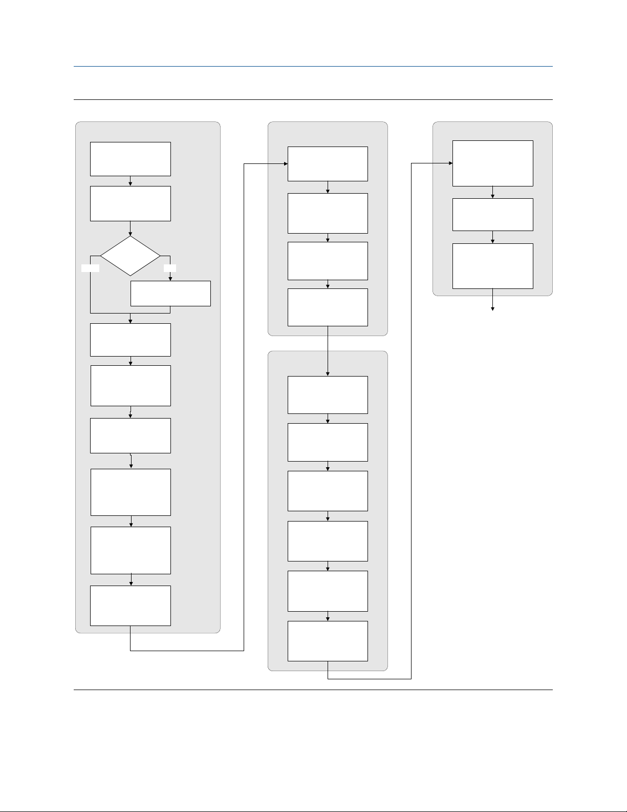
3.1 Configuration flowchart
Use the following flowchart as a general guide to the configuration and commissioning
process.
Some options may not apply to your installation. Detailed information is provided in the
remainder of this manual. If you are using the Weights & Measures application, additional
configuration and setup are required.
Configuration and Use Manual 21
Introduction to configuration and commissioning
Configuration flowchartFigure 3-1:
Configure process measurement
Configure device options and
preferences
Test and move to production
Configure mass flow
measurement
Configure volume flow
meaurement
Volume flow type
Liquid
Configure flow direction
Configure density
measurement
Configure temperature
measurement
Gas
Define gas properties
Configure display
parameters
Configure fault handling
parameters
Configure sensor
parameters
Configure device
parameters
Integrate device with control system
Configure the channel(s)
Configure the mA
output(s)
Test or tune transmitter
using sensor simulation
Back up transmitter
configuration
Enable write-protection on
transmitter configuration
Done
Configure petroleum
measurement (API)
application (if available)
Configure concentration
measurement application
(if available)
Configure pressure
compensation (optional)
Configure the frequency
output(s)
Configure the discrete
output(s)
Configure events
Configure digital
communications
22 Micro Motion® Model 2700 Transmitters with Analog Outputs
Loading...