


Installation Manual
Micro Motion™ ELITE™ Coriolis Flow and
Density Sensors
20002158, Rev DP
June 2022

Safety messages
Safety messages are provided throughout this manual to protect personnel and equipment. Read each safety message carefully
before proceeding to the next step.
Safety and approval information
This Micro Motion product complies with all applicable European directives when properly installed in accordance with the
instructions in this manual. Refer to the EU declaration of conformity for directives that apply to this product. The following are
available: the EU Declaration of Conformity, with all applicable European directives, and the complete ATEX installation drawings
and instructions. In addition, the IECEx installation instructions for installations outside of the European Union and the CSA
installation instructions for installations in North America are available at Emerson.com or through your local Micro Motion
support center.
Information affixed to equipment that complies with the Pressure Equipment Directive, can be found at Emerson.com. For
hazardous installations in Europe, refer to standard EN 60079-14 if national standards do not apply.
Other information
Troubleshooting information can be found in the Configuration Manual. Product data sheets and manuals are available from the
Micro Motion web site at Emerson.com.
Return policy
Follow Micro Motion procedures when returning equipment. These procedures ensure legal compliance with government
transportation agencies and help provide a safe working environment for Micro Motion employees. Micro Motion will not accept
your returned equipment if you fail to follow Micro Motion procedures.
Return procedures and forms are available on our web support site at Emerson.com, or by calling the Micro Motion Customer
Service department.
2

Installation Manual Contents
20002158 June 2022
Contents
Chapter 1 Before you begin........................................................................................................5
1.1 About this document...................................................................................................................5
1.2 Hazard messages.........................................................................................................................5
1.3 Related documentation............................................................................................................... 5
Chapter 2 Planning.................................................................................................................... 7
2.1 Installation checklist.................................................................................................................... 7
2.2 Best practices.............................................................................................................................. 8
2.3 Temperature limits...................................................................................................................... 9
2.4 Recommendations for hygienic and self-draining applications...................................................12
Chapter 3 Mounting.................................................................................................................15
3.1 Recommendations for lifting heavy meters............................................................................... 15
3.2 Mount the sensor.......................................................................................................................17
3.3 Rotate junction box or 800 core processor (optional).................................................................18
3.4 Mount electronics of high-temperature sensors........................................................................ 19
3.5 Mount a CMF010 sensor to a wall or pole................................................................................... 22
3.6 Mount a CMFS007, CMFS010, or CMFS015 sensor in a bracket.................................................. 23
3.7 Mount a CMFS025, CMFS040, or CMFS050 sensor in a wall mount bracket................................24
3.8 Secure wafer-style process connections.....................................................................................25
3.9 Attach extended electronics...................................................................................................... 26
Chapter 4 Transmitter power and I/O wiring............................................................................ 29
4.1 Options for wiring......................................................................................................................29
4.2 Connect 4-wire cable................................................................................................................. 30
4.3 Connect the 9-wire cable .......................................................................................................... 35
Chapter 5 Grounding................................................................................................................37
Chapter 6 Supplementary information.....................................................................................39
6.1 Purge the sensor case ................................................................................................................39
6.2 Pressure relief............................................................................................................................ 41
Installation Manual 3

Contents Installation Manual
June 2022 20002158
4 Micro Motion ELITE

Installation Manual Before you begin
20002158 June 2022
1 Before you begin
1.1 About this document
This document provides information on planning, mounting, wiring, and grounding the
ELITE sensor.
The information in this document assumes that users understand basic transmitter and
sensor installation, configuration, and maintenance concepts and procedures.
1.2 Hazard messages
This document uses the following criteria for hazard messages based on ANSI standards
Z535.6-2011 (R2017).
DANGER
Serious injury or death will occur if a hazardous situation is not avoided.
WARNING
Serious injury or death could occur if a hazardous situation is not avoided.
CAUTION
Minor or moderate injury will or could occur if a hazardous situation is not avoided.
NOTICE
Data loss, property damage, hardware damage, or software damage can occur if a
situation is not avoided. There is no credible risk of physical injury.
Physical access
WARNING
Unauthorized personnel can potentially cause significant damage and/or
misconfiguration of end users' equipment. Protect against all intentional or
unintentional unauthorized use.
Physical security is an important part of any security program and fundamental to
protecting your system. Restrict physical access to protect users' assets. This is true for
all systems used within the facility.
1.3 Related documentation
You can find all product documentation at Emerson.com.
See any of the following documents for more information:
Installation Manual 5

Before you begin Installation Manual
June 2022 20002158
• The hazardous area approvals documentation shipped with the sensor or available at
www.emerson.com/flowmeasurement.
• Micro Motion ELITE Coriolis Flow and Density Meters Product Data Sheet
• Micro Motion 9-Wire Flowmeter Cable Preparation and Installation Manual
• Micro Motion High Temperature Solutions Best Practices Guide
• The transmitter installation guide and the transmitter configuration and use guide
6 Micro Motion ELITE

Installation Manual
20002158 June 2022
Planning
2 Planning
2.1 Installation checklist
□ If you plan to mount the transmitter in a hazardous area:
WARNING
Make sure that the hazardous area specified on the approval tag is suitable for the
environment in which the meter will be installed.
□ Verify that the local ambient and process temperatures are within the limits of the
meter.
□ If your sensor has an integral transmitter, no wiring is required between the sensor and
transmitter. Follow the wiring instructions in the transmitter installation manual for
signal and power wiring.
□ If your transmitter has remote-mounted electronics, follow the instructions in this
manual for wiring between the sensor and the transmitter, and then follow the
instructions in the transmitter installation manual for power and signal wiring.
Table 2-1: Maximum lengths for Micro Motion cable
Cable type To transmitter Maximum length
Micro Motion 9-wire 9739 MVD transmitter 1,000 ft (305 m)
All other MVD transmitters 60 ft (18 m)
Micro Motion 4-wire All 4-wire MVD transmitters — 1,000 ft (305 m) without
Ex-approval
— 500 ft (152 m) with IIC
rated sensors
— 1,000 ft (305 m) with IIB
rated sensors
Table 2-2: Maximum lengths for user-supplied 4-wire cable
Wire function Wire size Maximum length
Power (VDC) 22 AWG (0.326 mm²) 300 ft (91 m)
20 AWG (0.518 mm²) 500 ft (152 m)
18 AWG (0.823 mm²) 1,000 ft (305 m)
Signal (RS-485) 22 AWG (0.326 mm²) or larger 1,000 ft (305 m)
□ For optimal performance, install the sensor in the preferred orientation. The sensor will
work in any orientation as long as the flow tubes remain full of process fluid.
Installation Manual 7

Planning
June 2022 20002158
Table 2-3: Preferred sensor orientation
Installation Manual
Process
Liquids & slurries
Gases
Primary preferred
orientation
Liquid with bubbles Wet gas
Secondary preferred
orientation
Alternate suitable
orientation
Two-phase
□ Install the meter so that the flow direction arrow on the sensor case matches the actual
forward flow of the process. (Flow direction is also software-selectable.)
2.2 Best practices
• There are no pipe run requirements for Micro Motion sensors. Straight runs of pipe
upstream or downstream are unnecessary.
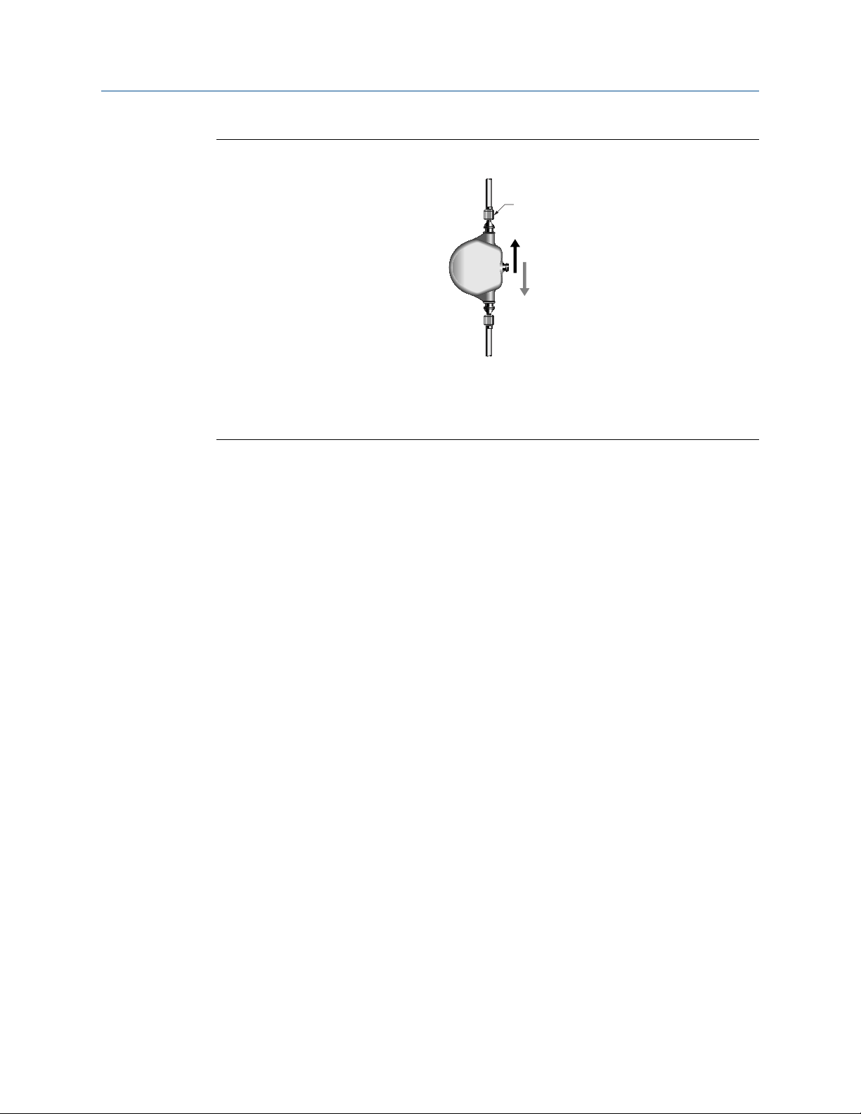
• If the sensor is installed in a vertical pipeline, liquids and slurries should flow upward
through the sensor. Gases should flow downward.
• Keep the sensor tubes full of process fluid.
• For halting flow through the sensor with a single valve, install the valve downstream
from the sensor.
8 Micro Motion ELITE

Installation Manual
20002158 June 2022
• The sensor does not require external supports. The flanges will support the sensor in
any orientation. (Some sensor models installed in very small, flexible pipeline have
optional installation instructions that allow for external supports.)
Planning
2.2.1 High temperature best practices
• Perform steam injection downstream of the Coriolis meter
• Use steam traps to eliminate condensation and steam flashing
• Control fast acting valves to prevent hammer shock
• Install the meter symmetrically (not tilted)
• Use heat jacket symmetrically (avoid electric or oil trace on just one side)
• To avoid plugging for plugging prone applications, apply heat slowly and uniformly
during startup
• Perform slow and controlled switch-over from ethane to de-coking process
For more information, refer to the Micro Motion High Temperature Solutions Best
Practices Guide.
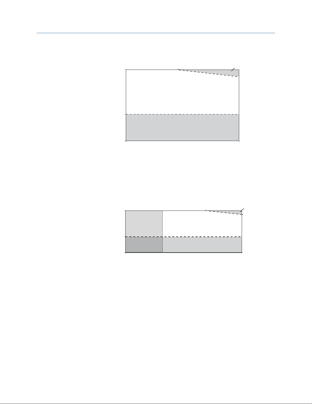
2.3 Temperature limits
Sensors can be used in the process and ambient temperature ranges shown in the
temperature limit graphs. For the purposes of selecting electronics options, temperature
limit graphs should be used only as a general guide. If your process conditions are close to
the gray area, consult with your Micro Motion representative.
WARNING
Temperature limits may be further restricted by hazardous area approvals that are
necessary to avoid potential injury to personnel and damage to equipment. Refer to the
hazardous area approvals documentation shipped with the sensor or available at
www.emerson.com/flowmeasurement for specific temperature ratings for each model
and configuration.
Note
• In all cases, the electronics cannot be operated where the ambient temperature is
below -40 °F (-40 °C) or above 140 °F (60 °C). If a sensor is to be used where the ambient
temperature is outside of the range permissible for the electronics, the electronics
must be remotely located where the ambient temperature is within the permissible
range, as indicated by the shaded areas of the temperature limit graphs.
• The extended-mount electronics option allows the sensor case to be insulated without
covering the transmitter, core processor, or junction box, but does not affect
temperature ratings. When insulating the sensor case at elevated process
temperatures above 140 °F (60 °C), ensure electronics are not enclosed in insulation as
this may lead to electronics failure.
• For the CMFS007 sensor, the difference between the process fluid temperature and the
average temperature of the case must be less than 210 °F (99 °C)
Installation Manual 9
140 (60)
–40 (–40)
113
(45)
–148 (–100)
–400
(–240)
400
(204)
140
(60)
T amb
T proc
A
B
B
C
-148
(-100)
Planning Installation Manual
June 2022 20002158
Ambient and process temperature limits for CMFS007, CMFS025–CMFS150
B
113
(45)
Tamb
–40 (–40)
140 (60)
140 (60)
A
B
–148 (–100)
–58 (–50) 400 (204)
T
= Ambient temperature °F (°C)
amb
T
= Process temperature °F (°C)
proc
A = All available electronic options
B= Remote mount electronics only
Ambient and process temperature limits for CMF***M/L/H/P (excludes special order
cryogenic modifications) and CMFS010-015
Tproc
T
= Ambient temperature °F (°C)
amb
T
= Process temperature °F (°C)
proc
A = All available electronic options
B = Remote mount electronics only
C = Recommend special order cryogenic sensor options when operating at a process
temperature below -148 °F (-100 °C)
10 Micro Motion ELITE

Installation Manual Planning
20002158 June 2022
Ambient and process temperature limits for special order cryogenic ELITE meters
140 (60)
Tamb
–40 (–40)
A
B
–148 (–100)
–400
(–240)
T
= Ambient temperature °F (°C)
amb
T
= Process temperature °F (°C)
proc
Tproc
A = All available electronic options
B= Remote mount electronics only
Ambient and process temperature limits for high temperature ELITE meters
140 (60)
176
(80)
Tamb
–40 (–40)
–148 (–100)
T
= Ambient temperature °F (°C)
amb
T
= Process temperature °F (°C)
proc
A = All available electronic options
B= Remote mount electronics only
–58
(–50)
A
B
Tproc
662
(350)
Installation Manual 11

Planning Installation Manual
June 2022 20002158
Ambient and process temperature limits for super duplex ELITE meters
140 (60)
140 (60)
B
113
(45)
Tamb
–40 (–40)
–148 (–100)
–40 (–40) 400 (204)
T
= Ambient temperature °F (°C)
amb
T
= Process temperature °F (°C)
proc
A
B
Tproc
A = All available electronic options
B= Remote mount electronics only
Note
For super duplex models operating above 351 °F (177.2 °C), consult the factory before
purchase.
2.4 Recommendations for hygienic and selfdraining applications
CMFS sensors are certified EHEDG TYPE EL CLASS I for hygienic applications when installed
vertically with the process fitting and gasket combinations listed in the Position Paper of
the EHEDG Test Methods Subgroup (available at https://www.ehedg.org). Other process
connections/gasket combinations may be used provided they have been evaluated and
successfully tested for in-place cleanability according to the latest edition of EHEDG
Document 2. Refer to the Micro Motion ELITE Coriolis Flow and Density Meters Product
Data Sheet for further information about fitting options.
For optimal cleanability and drainability:
• If possible, install the sensor in a vertical pipeline with the process fluid flowing upward
through the sensor.
• If the sensor must be installed in a horizontal pipeline, drainage is accomplished by air
purge evacuation of the pipeline circuit.
• For clean-in-place (CIP) applications, Micro Motion recommends using the generally-
accepted flow velocity of at least 1.5 m/s for cleaning the sensor.
• The gap between the electronics housing and sensor body should be inspected
periodically. Manually clean this gap when necessary.
12 Micro Motion ELITE
A
B
C
Installation Manual Planning
20002158 June 2022
Figure 2-1: Installation for self-draining applications
A. Process pipeline
B. Direction of normal process flow
C. Direction of drainage
Installation Manual 13

Planning Installation Manual
June 2022 20002158
14 Micro Motion ELITE
 Loading...