


Configuration and Use Manual
MMI- 20070546, Rev AB
Micro Motion™ 5700 Transmitters with
PROFIBUS®-PA
Configuration and Use Manual
June 2021

Safety messages
Safety messages are provided throughout this manual to protect personnel and equipment. Read each safety message carefully
before proceeding to the next step.
Safety and approval information
This Micro Motion product complies with all applicable European directives when properly installed in accordance with the
instructions in this manual. Refer to the EU declaration of conformity for directives that apply to this product. The following are
available: the EU declaration of conformity, with all applicable European directives, and the complete ATEX Installation Drawings
and Instructions. In addition the IECEx Installation Instructions for installations outside of the European Union and the CSA
Installation Instructions for installations in North America are available on the internet at www.emerson.com or through your local
Micro Motion support center.
Information affixed to equipment that complies with the Pressure Equipment Directive, can be found on the internet at
www.emerson.com. For hazardous installations in Europe, refer to standard EN 60079-14 if national standards do not apply.
Other information
Full product specifications can be found in the product data sheet. Troubleshooting information can be found in the configuration
manual. Product data sheets and manuals are available from the Micro Motion web site at www.emerson.com.
Return policy
Follow Micro Motion procedures when returning equipment. These procedures ensure legal compliance with government
transportation agencies and help provide a safe working environment for Micro Motion employees. Micro Motion will not accept
your returned equipment if you fail to follow Micro Motion procedures.
Return procedures and forms are available on our web support site at www.emerson.com, or by phoning the Micro Motion
Customer Service department.
Emerson Flow customer service
Email:
• Worldwide: flow.support@emerson.com
• Asia-Pacific: APflow.support@emerson.com
Telephone:
North and South America
United States 800-522-6277 U.K. and Ireland 0870 240 1978 Australia 800 158 727
Canada +1 303-527-5200 The Netherlands +31 (0) 70 413
Mexico +52 55 5809 5010 France +33 (0) 800 917
Argentina +54 11 4809 2700 Germany 0800 182 5347 Pakistan 888 550 2682
Brazil +55 15 3413 8000 Italy +39 8008 77334 China +86 21 2892 9000
Chile +56 2 2928 4800 Central & Eastern +41 (0) 41 7686
Peru +51 15190130 Russia/CIS +7 495 995 9559 South Korea +82 2 3438 4600
Europe and Middle East Asia Pacific
New Zealand 099 128 804
6666
India 800 440 1468
901
Japan +81 3 5769 6803
111
Egypt 0800 000 0015 Singapore +65 6 777 8211
Oman 800 70101 Thailand 001 800 441 6426
Qatar 431 0044 Malaysia 800 814 008
Kuwait 663 299 01
South Africa 800 991 390
Saudi Arabia 800 844 9564
UAE 800 0444 0684
2

Configuration and Use Manual Contents
MMI- 20070546 June 2021
Contents
Chapter 1 Before you begin........................................................................................................7
1.1 About this manual....................................................................................................................... 7
1.2 Hazard messages.........................................................................................................................7
1.3 Related documents......................................................................................................................8
1.4 Communication methods............................................................................................................8
Chapter 2 Quick start................................................................................................................. 9
2.1 Power up the transmitter.............................................................................................................9
2.2 Check meter status......................................................................................................................9
2.3 Determine PROFIBUS PA device address and Ident Selection using the display...........................10
2.4 Commissioning wizards............................................................................................................. 10
2.5 Make a startup connection to the transmitter............................................................................11
2.6 Set the transmitter clock............................................................................................................11
2.7 View the licensed features......................................................................................................... 11
2.8 Set informational parameters.................................................................................................... 12
2.9 Characterize the meter (if required)...........................................................................................13
2.10 Verify mass flow measurement................................................................................................16
2.11 Verify the zero......................................................................................................................... 16
Chapter 3 Introduction to configuration and commissioning....................................................19
3.1 Security and write protection.....................................................................................................19
3.2 Work with configuration files.....................................................................................................23
Chapter 4 Configure process measurement..............................................................................29
4.1 Configure Sensor Flow Direction Arrow .....................................................................................29
4.2 Configure mass flow measurement........................................................................................... 30
4.3 Configure volume flow measurement for liquid applications..................................................... 35
4.4 Configure Gas Standard Volume (GSV) flow measurement........................................................39
4.5 Configure density measurement................................................................................................44
4.6 Configure temperature measurement....................................................................................... 47
4.7 Configure Pressure Measurement Unit ......................................................................................49
4.8 Configure Velocity Measurement Unit ...................................................................................... 50
4.9 Energy flow................................................................................................................................50
4.10 Piecewise linearization (PWL) for calibrating gas meters.......................................................... 52
Chapter 5 Configure process measurement applications.......................................................... 53
5.1 Set up the API Referral application ............................................................................................ 53
5.2 Set up concentration measurement...........................................................................................65
Chapter 6 Configure advanced options for process measurement............................................ 81
6.1 Configure Response Time ......................................................................................................... 81
Configuration and Use Manual 3

Contents Configuration and Use Manual
June 2021 MMI- 20070546
6.2 Detect and report two-phase flow............................................................................................. 81
6.3 Configure Flow Rate Switch .......................................................................................................83
6.4 Configure events....................................................................................................................... 84
6.5 Configure totalizers and inventories.......................................................................................... 86
6.6 Configure logging for totalizers and inventories.........................................................................90
6.7 Configure Process Variable Fault Action .................................................................................... 90
Chapter 7 Configure device options and preferences................................................................ 95
7.1 Configure the transmitter display.............................................................................................. 95
7.2 Configure the transmitter's response to alerts......................................................................... 101
7.3 Control button sensitivity on the display..................................................................................109
Chapter 8 Integrate the meter with the control system.......................................................... 111
8.1 Configure PROFIBUS-PA Channel A.......................................................................................... 111
8.2 Configure mA Output Channel B..............................................................................................111
8.3 Configure FO/DO Channel C.................................................................................................... 120
Chapter 9 Complete the configuration................................................................................... 131
9.1 Test or tune the system using sensor simulation......................................................................131
9.2 Enable or disable software write-protection.............................................................................132
Chapter 10 Transmitter operation............................................................................................ 135
10.1 View process and diagnostic variables................................................................................... 135
10.2 View and acknowledge status alerts...................................................................................... 136
10.3 Read totalizer and inventory values........................................................................................137
10.4 Start, stop, and reset totalizers and inventories..................................................................... 137
Chapter 11 Measurement support............................................................................................141
11.1 Use Smart Meter Verification................................................................................................. 141
11.2 Zero the meter...................................................................................................................... 148
11.3 Set up pressure compensation...............................................................................................151
11.4 Validate the meter.................................................................................................................154
11.5 Perform a (standard) D1 and D2 density calibration...............................................................156
11.6 Adjust concentration measurement with Trim Slope and Trim Offset ................................... 159
Chapter 12 Maintenance.......................................................................................................... 161
12.1 Install a new transmitter license.............................................................................................161
12.2 Upgrade the transmitter firmware......................................................................................... 162
12.3 Reboot the transmitter.......................................................................................................... 163
12.4 Battery replacement..............................................................................................................164
Chapter 13 Log files, history files, and service files....................................................................165
13.1 Generate history files.............................................................................................................165
13.2 Generate service files.............................................................................................................171
Chapter 14 Troubleshooting.................................................................................................... 179
14.1 Status LED and device status..................................................................................................179
4 Micro Motion 5700 Transmitters with PROFIBUS-PA

Configuration and Use Manual Contents
MMI- 20070546 June 2021
14.2 API Referral troubleshooting..................................................................................................179
14.3 Concentration measurement troubleshooting...................................................................... 180
14.4 Alert when connecting a core processor to a remote 5700 transmitter..................................181
14.5 Density measurement troubleshooting................................................................................. 182
14.6 Discrete Output troubleshooting...........................................................................................184
14.7 Flow measurement troubleshooting......................................................................................185
14.8 Frequency Output troubleshooting....................................................................................... 187
14.9 mA Output troubleshooting.................................................................................................. 189
14.10 Status alerts, causes, and recommendations....................................................................... 192
14.11 Perform a core processor resistance test..............................................................................211
14.12 Check the cutoffs.................................................................................................................213
14.13 Check the direction parameters...........................................................................................213
14.14 Check the drive gain............................................................................................................ 213
14.15 Check for internal electrical problems..................................................................................214
14.16 Check Frequency Output Fault Action .................................................................................215
14.17 Check the scaling of the Frequency Output..........................................................................215
14.18 Check grounding................................................................................................................. 215
14.19 Perform loop tests............................................................................................................... 216
14.20 Check Lower Range Value and Upper Range Value ..............................................................220
14.21 Check mA Output Fault Action ............................................................................................220
14.22 Trim mA Output.................................................................................................................. 220
14.23 Check the pickoff voltage.................................................................................................... 221
14.24 Check power supply wiring.................................................................................................. 222
14.25 Check for radio frequency interference (RFI)........................................................................ 222
14.26 Check sensor-to-transmitter wiring..................................................................................... 223
14.27 Check the sensor coils..........................................................................................................223
14.28 Using sensor simulation for troubleshooting....................................................................... 225
14.29 Check for two-phase flow (slug flow)................................................................................... 225
14.30 Simulation problems........................................................................................................... 226
14.31 Temperature measurement troubleshooting...................................................................... 228
14.32 Velocity measurement troubleshooting.............................................................................. 229
Appendix A 5700 PROFIBUS-PA transducer blocks.....................................................................231
A.1 Transducer block overview...................................................................................................... 231
A.2 Slot identification.................................................................................................................... 232
A.3 PROFIBUS-PA parameters 0 through 7..................................................................................... 233
A.4 I & M functions.........................................................................................................................234
A.5 Physical block.......................................................................................................................... 237
A.6 Totalizer block parameters (slots 4, 6, 7, and 8)....................................................................... 242
A.7 Analog Output block parameters (slots 9 and 10)....................................................................246
A.8 Analog Input block parameters (slots 1, 2, 3, and 5)................................................................ 251
A.9 Discrete Output block parameters (slot 11)............................................................................. 255
Configuration and Use Manual 5

Contents Configuration and Use Manual
June 2021 MMI- 20070546
A.10 Discrete Input block parameters (slot 12).............................................................................. 260
A.11 PROFIBUS-PA channels.......................................................................................................... 263
A.12 Measurement parameters (slot 13)....................................................................................... 269
A.13 Device slot parameters (slot 14)............................................................................................ 292
A.14 Configurable totalizer and inventory block parameters (slot 15)............................................317
A.15 Smart Meter Verification block parameters (slot 16)..............................................................332
A.16 API process variables block parameters (slot 17)....................................................................342
A.17 Concentration measurement block parameters (slot 18).......................................................344
A.18 Advanced Phase Measurement block parameters (slot 19).................................................... 349
Appendix B PROFIBUS PA function blocks..................................................................................359
B.1 Function block overview.......................................................................................................... 359
B.2 Analog Input function block.....................................................................................................363
B.3 Totalizer function block........................................................................................................... 365
B.4 Analog Output function block..................................................................................................368
B.5 Discrete Output function block................................................................................................371
B.6 Discrete Input function block...................................................................................................372
B.7 Slave diagnostic response........................................................................................................374
B.8 Alerts.......................................................................................................................................378
Appendix C Using the transmitter display................................................................................. 381
C.1 Components of the transmitter display................................................................................... 381
C.2 Access and use the display menus........................................................................................... 383
Appendix D Using ProLink III with the transmitter..................................................................... 387
D.1 Connect with ProLink III .......................................................................................................... 387
Appendix E Concentration measurement matrices, derived variables, and process variables.... 389
E.1 Standard matrices for the concentration measurement application.........................................389
E.2 Derived variables and calculated process variables...................................................................390
Appendix F Environmental compliance.....................................................................................393
F.1 RoHS and WEEE........................................................................................................................393
6 Micro Motion 5700 Transmitters with PROFIBUS-PA

Configuration and Use Manual Before you begin
MMI- 20070546 June 2021
1 Before you begin
1.1 About this manual
This manual helps you configure, commission, use, maintain, and troubleshoot Micro Motion 5700
transmitters with PROFIBUS-PA.
Important
This manual assumes that:
• The transmitter has been installed correctly and completely according to the instructions in the
transmitter installation manual
• Users understand basic transmitter and sensor installation, configuration, and maintenance concepts and
procedures
1.2 Hazard messages
This document uses the following criteria for hazard messages based on ANSI standards Z535.6-2011
(R2017).
DANGER
Serious injury or death will occur if a hazardous situation is not avoided.
WARNING
Serious injury or death could occur if a hazardous situation is not avoided.
CAUTION
Minor or moderate injury will or could occur if a hazardous situation is not avoided.
NOTICE
Data loss, property damage, hardware damage, or software damage can occur if a situation is not avoided.
There is no credible risk of physical injury.
Physical access
NOTICE
Unauthorized personnel can potentially cause significant damage and/or misconfiguration of end users'
equipment. Protect against all intentional or unintentional unauthorized use.
Physical security is an important part of any security program and fundamental to protecting your system.
Restrict physical access to protect users' assets. This is true for all systems used within the facility.
Configuration and Use Manual 7

Before you begin Configuration and Use Manual
June 2021 MMI- 20070546
1.3 Related documents
You can find all product documentation on the product documentation DVD shipped with the product or at
www.emerson.com.
See any of the following documents for more information:
• Micro Motion 5700 Product Data Sheet
• Micro Motion 5700 Transmitters for PROFIBUS-PA: Installation Manual
• Replacing the Junction Box for the 4200 Transmitter and the 5700 Transmitter
• Replacing the Sensor Cable for the 4200 Transmitter and the 5700 Transmitter
• Sensor installation manual
1.4 Communication methods
You can use several different communications methods to interface with the transmitter. You may use
different methods in different locations or for different tasks.
Interface Tool
Display Infrared-sensitive buttons
Universal Service Port ProLink™ III
PROFIBUS PA channel PROFIBUS-PA host
On a PROFIBUS-PA host, the transmitter parameters are displayed in UIRD form
(for example, the AMS intelligent Device Manager with DeltaV™ or Siemens
PDM)
For information about how to use the communication tools, see the appendices in this manual.
®
8 Micro Motion 5700 Transmitters with PROFIBUS-PA

Configuration and Use Manual Quick start
MMI- 20070546 June 2021
2 Quick start
2.1 Power up the transmitter
The transmitter must be powered up for all configuration and commissioning tasks, or for process
measurement.
Procedure
1. Verify that all transmitter and sensor covers and seals are closed.
WARNING
To prevent ignition of flammable or combustible atmospheres, ensure that all covers and seals are
tightly closed. For hazardous area installations, applying power while housing covers are removed or
loose can cause an explosion resulting in injury or death.
2. Turn on the electrical power at the power supply.
Postrequisites
Although the sensor is ready to receive process fluid shortly after power-up, the electronics can take up to
10 minutes to reach thermal equilibrium. Therefore, if this is the initial startup, or if power has been off long
enough to allow components to reach ambient temperature, allow the electronics to warm up for
approximately 10 minutes before relying on process measurements. During this warm-up period, you may
observe minor measurement instability or inaccuracy.
2.2 Check meter status
Check the meter for any error conditions that require user action or that affect measurement accuracy.
Procedure
1. Wait approximately 10 seconds for the power-up sequence to complete.
Immediately after power-up, the transmitter runs through diagnostic routines and checks for error
conditions. During the power-up sequence, the Transmitter Initializing alert is active. This
alert should clear automatically when the power-up sequence is complete.
2. Check the status LED on the transmitter.
Table 2-1: Status LED and device status
Status LED condition Device status
Solid green No alerts are active.
Solid yellow One or more alerts are active with Alert Severity = Out of Specification,
Maintenance Required, or Function Check.
Solid red One or more alerts are active with Alert Severity = Failure.
Flashing yellow (1 Hz) The Function Check in Progress alert is active.
Configuration and Use Manual 9

Quick start Configuration and Use Manual
June 2021 MMI- 20070546
Table 2-2: Network status LED connection status
Network status LED condition Network status
Solid green Connection made with primary protocol host.
Solid red Configuration error or other error during the PROFIBUS start up sequence.
Off No connection with primary protocol host.
2.3 Determine PROFIBUS PA device address and Ident
Selection using the display
You can configure the 5700 address using either of the following methods:
• Hardware addressing
• Software addressing
For more information, see Addressing.
Procedure
1. To determine the PROFIBUS-PA device address, choose Menu → Configuration → Profibus-PA Setting
→ Profibus PA Address.
• The 5700 address is configurable if the BCD switches at the back of the printed circuit assembly
(PCA) on the display are set > 125.
• If you change the 5700 address from the display, power cycle the 5700 so that the new address gets
used for PROFIBUS-PA communication.
2. To determine the PROFIBUS-PA Ident Selection, choose Menu → Configuration → Profibus-PA Setting
→ Ident Selection.
2.4 Commissioning wizards
The transmitter menu includes a Guided Setup to help you move quickly through the most common
configuration parameters. ProLink III also provides a commissioning wizard.
By default, when the transmitter starts up, the Guided Setup menu is offered. You can choose to use it or not.
You can also choose whether or not Guided Setup is displayed automatically.
• To enter Guided Setup upon transmitter startup, choose Yes at the prompt.
• To enter Guided Setup after transmitter startup, choose Menu → Startup Tasks.
• To control the automatic display of Guided Setup, choose Menu → Configuration → Guided Setup.
For information on the ProLink III commissioning wizard, see the Micro Motion ProLink III with ProcessViz
Software User Manual.
As the commissioning wizards are self guided, they are not documented in detail.
10 Micro Motion 5700 Transmitters with PROFIBUS-PA

Configuration and Use Manual Quick start
MMI- 20070546 June 2021
2.5 Make a startup connection to the transmitter
For all configuration tools except the display, you must have an active connection to the transmitter to
configure the transmitter.
Procedure
Identify the connection type to use, and follow the instructions for that connection type in the appropriate
appendix.
2.6 Set the transmitter clock
Display Menu → Configuration → Time/Date/Tag
ProLink III Device Tools → Configuration → Transmitter Clock
The transmitter clock provides timestamp data for alerts, service logs, history logs, and all other timers and
dates in the system. You can set the clock for your local time or for any standard time you want to use.
Tip
You may find it convenient to set all of your transmitter clocks to the same time, even if the transmitters are
in different time zones.
Procedure
1. Select the time zone that you want to use.
2. If you need a custom time zone, select Special Time Zone and enter your time zone as a difference
from UTC (Coordinated Universal Time).
3. Set the time appropriately for the selected time zone.
Tip
The transmitter does not adjust for Daylight Savings Time. If you observe Daylight Savings Time, you
must reset the transmitter clock manually.
4. Set the month, day, and year.
The transmitter tracks the year and automatically adds a day for leap years.
2.7 View the licensed features
Display
ProLink III Device Tools → Device Information → Licensed Features
DeltaV AMS Overview → Device Information → Licenses
Siemens PDM view → Overview → Device Information → Licenses
You can view the licensed features to ensure that the transmitter was ordered with the required features.
Menu → About → Licenses → Licensed Features
Licensed features are purchased and available for permanent use. The options model code represents the
licensed features.
Configuration and Use Manual 11

Quick start Configuration and Use Manual
June 2021 MMI- 20070546
A trial license allows you to explore features before purchasing. The trial license enables the specified features
for a limited number of days. This number is displayed for reference. At the end of this period, the feature will
no longer be available.
To purchase additional features or request a trial license, document the Unique ID Number and current
license key from your transmitter and contact customer service. To enable the additional features or trial
license, you will need to install the new license on the transmitter.
2.8 Set informational parameters
Display Menu → Configuration → Device Information
ProLink III Device Tools → Configuration → Informational Parameters
DeltaV AMS Configure → Manual Setup → Device
Siemens PDM Device → Manual Setup → Device
You can set several parameters that identify or describe the transmitter and sensor. These parameters are not
used in processing and are not required.
Procedure
1. Set informational parameters for the transmitter.
a) Set Transmitter Serial Number to the serial number of your transmitter.
The transmitter serial number is provided on the metal tag that is attached to the transmitter
housing.
b) Set Descriptor to any desired description of this transmitter or measurement point.
c) Set Message to any desired message.
d) Verify that Model Code (Base) is set to the base model code of the transmitter.
The base model code completely describes your transmitter, except for the features that can be
licensed independently. The base model code is set at the factory.
e) Set Model Code (Options) to the options model code of the transmitter.
The options model code describes the independent features that have been licensed for this
transmitter. The original options model code is set at the factory. If you license additional
options for this transmitter, Micro Motion will supply an updated options model code.
2. Set informational parameters for the sensor.
a) Set Sensor Serial Number to the serial number of the sensor connected to this transmitter.
The sensor serial number is provided on the metal tag that is attached to the sensor case.
b) Set Sensor Material to the material used for the sensor.
c) Set Sensor Liner to the material used for the sensor liner, if any.
d) Set Flange Type to the type of flange that was used to install the sensor.
12 Micro Motion 5700 Transmitters with PROFIBUS-PA

Configuration and Use Manual Quick start
MMI- 20070546 June 2021
Do not set Sensor Type. Sensor Type is set or derived during characterization.
2.9 Characterize the meter (if required)
Display Menu → Configuration → Sensor Parameters
ProLink III Device Tools → Calibration Data
DeltaV AMS Configure → Manual Setup → Characterization
Siemens PDM Device → Manual Setup → Characterization
Characterizing the meter adjusts your transmitter to match the unique traits of the sensor it is paired with.
The characterization parameters (also called calibration parameters) describe the sensor’s sensitivity to flow,
density, and temperature. Depending on your sensor type, different parameters are required.
Values for your sensor are provided on the sensor tag or the calibration certificate.
• If your transmitter was ordered with a sensor, it was characterized at the factory. However, you should still
verify the characterization parameters.
• Perform a characterization whenever you replace a core processor.
Procedure
1. Optional: Specify Sensor Type.
• Straight Tube (T-Series sensors)
• Curved Tube (all sensors except T-Series)
Note
Unlike earlier transmitters, the 5700 derives Sensor Type from the user-specified values for FCF and K1
in combination with an internal ID.
2. Set the flow calibration factor: FCF (also called Flow Cal or Flow Calibration Factor). Be sure to include
all decimal points.
3. Set the density characterization parameters: D1, D2, TC, K1, K2, and FD. (TC is sometimes shown as
DT.)
4. Apply the changes as required by the tool you are using.
The transmitter identifies your sensor type, and characterization parameters are adjusted as required:
• If Sensor Type changed from Curved Tube to Straight Tube, five characterization parameters are
added to the list.
• If Sensor Type changed from Straight Tube to Curved Tube, five characterization parameters are
removed from the list.
• If Sensor Type did not change, the list of characterization parameters does not change.
5. T-Series sensors only: Set the additional characterization parameters listed below.
Characterization parameter type
Flow FTG, FFQ
Configuration and Use Manual 13
Parameters
Quick start Configuration and Use Manual
June 2021 MMI- 20070546
Characterization parameter type Parameters
Density DTG, DFQ1, DFQ2
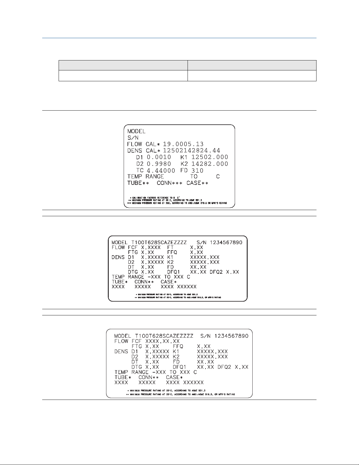
2.9.1 Sample sensor tags
Figure 2-1: Tag on newer curved-tube sensors (all sensors except T-Series)
Figure 2-2: Tag on older straight-tube sensor (T-Series)
Figure 2-3: Tag on newer straight-tube sensor (T-Series)
14 Micro Motion 5700 Transmitters with PROFIBUS-PA

Configuration and Use Manual Quick start
MMI- 20070546 June 2021
2.9.2 Flow calibration parameters (FCF, FT)
Two separate values are used to describe flow calibration: a 6-character FCF value and a 4-character FT value.
They are provided on the sensor tag.
Both values contain decimal points. During characterization, these are entered as a single 10-character string.
The 10-character string is called either Flowcal or FCF.
If your sensor tag shows the FCF and the FT values separately and you need to enter a single value,
concatenate the two values to form the single parameter value, retaining both decimal points.
Concatenating FCF and FT
FCF = x.xxxx FT = y.yy Flow calibration parameter: x.xxxxy.yy
2.9.3 Density calibration parameters (D1, D2, K1, K2, FD, DT, TC)
Density calibration parameters are typically on the sensor tag and the calibration certificate.
If your sensor tag does not show a D1 or D2 value:
• For D1, enter the Dens A or D1 value from the calibration certificate. This value is the line-condition
density of the low-density calibration fluid. Micro Motion uses air. If you cannot find a Dens A or D1 value,
enter 0.001 g/cm3.
• For D2, enter the Dens B or D2 value from the calibration certificate. This value is the line-condition density
of the high-density calibration fluid. Micro Motion uses water. If you cannot find a Dens B or D2 value,
enter 0.998 g/cm3 .
If your sensor tag does not show a K1 or K2 value:
• For K1, enter the first five digits of the density calibration factor. In this sample tag, this value is shown as
12500.
• For K2, enter the second five digits of the density calibration factor. In this sample tag, this value is shown
as 14286.
Figure 2-4: K1, K2, and TC values in the density calibration factor
If your sensor does not show an FD value, contact customer service.
Configuration and Use Manual 15

Quick start Configuration and Use Manual
June 2021 MMI- 20070546
If your sensor tag does not show a DT or TC value, enter the last four characters of the density calibration
factor. In the sample tag shown above, the value is shown as 4.44.
Do not confuse the Meter Factor line on the pictured sensor tag with any meter factor settings discussed in
this manual.
2.10 Verify mass flow measurement
Check to see that the mass flow rate reported by the transmitter is accurate. You can use any available
method.
Procedure
• Read the value for Mass Flow Rate on the transmitter display.
• Connect to the transmitter with ProLink III and read the value for Mass Flow Rate in the Process Variables
panel.
Postrequisites
If the reported mass flow rate is not accurate:
• Check the characterization parameters.
• Review the troubleshooting suggestions for flow measurement issues.
2.11 Verify the zero
Display
ProLink III Device Tools → Calibration → Smart Zero Verification and Calibration → Verify Zero
DeltaV AMS Service Tools → Maintenance → Calibration → Zero Calibration → Perform Zero Verify
Siemens PDM Diagnostics → Maintenance → Calibration → Zero Calibration → Perform Zero Verify
Verifying the zero helps you determine if the stored zero value is appropriate to your installation, or if a field
zero can improve measurement accuracy.
Important
In most cases, the factory zero is more accurate than the field zero. Do not zero the meter unless one of the
following is true:
• The zero is required by site procedures.
• The stored zero value fails the zero verification procedure.
Do not verify the zero or zero the meter if a high-severity alert is active. Correct the problem, then verify the
zero or zero the meter. You may verify the zero or zero the meter if a low-severity alert is active.
Menu → Service Tools → Verification & Calibration → Meter Zero → Zero Verification
Procedure
1. Prepare the meter:
a) Allow the meter to warm up for at least 20 minutes after applying power.
b) Run the process fluid through the sensor until the sensor temperature reaches the normal
process operating temperature.
16 Micro Motion 5700 Transmitters with PROFIBUS-PA

Configuration and Use Manual Quick start
MMI- 20070546 June 2021
c) Stop flow through the sensor by shutting the downstream valve, and then the upstream valve if
available.
d) Verify that the sensor is blocked in, that flow has stopped, and that the sensor is completely full
of process fluid.
2. Start the zero verification procedure, and wait until it completes.
3. If the zero verification procedure fails:
a) Confirm that the sensor is completely blocked in, that flow has stopped, and that the sensor is
completely full of process fluid.
b) Verify that the process fluid is not flashing or condensing, and that it does not contain particles
that can settle out.
c) Repeat the zero verification procedure.
d) If it fails again, zero the meter.
Postrequisites
Restore normal flow through the sensor by opening the valves.
Related information
Zero the meter
Configuration and Use Manual 17

Quick start Configuration and Use Manual
June 2021 MMI- 20070546
18 Micro Motion 5700 Transmitters with PROFIBUS-PA

Configuration and Use Manual Introduction to configuration and commissioning
MMI- 20070546 June 2021
3 Introduction to configuration and commissioning
3.1 Security and write protection
The transmitter has several features that can help to protect it against intentional or unintentional access and
configuration changes.
• When locked, the mechanical lock switch on the front of the display prevents any configuration changes
to the transmitter from any local or remote configuration tool. A transmitter without a display does not
have a lock switch.
• When enabled, the software setting Write Protection prevents any configuration changes. The setting
can only be enabled if the transmitter does not have a display.
• If the Universal Service Port (USP) is disabled, the port cannot be used by any service tool to communicate
with or make changes to the transmitter.
• When enabled, Security prevents any configuration changes being made from the display unless the
appropriate password is entered.
• When enabled, the PROFIBUS PA write lock prevents any configuration changes being written from the
PROFIBUS PA segment.
3.1.1 Universal Service Port security
This transmitter is equipped with a Universal Service Port that works with USB type A connections, including
compatible flash drives. There are multiple levels of security built into the transmitter's service port that you
can configure according to your needs and security standards.
The service port offers the following features that enhance interface security:
• The service port is inaccessible without physical access to the transmitter and requires removal of the
terminal cover
• The service port can be disabled from the transmitter through software
• The transmitter has a non-traditional operating system that is not designed to execute programs or run
scripts
• The display can be password protected to limit access to the USB file menu
• Overall transmitter security switches such as the lock switch or write-protection disallows configuration
changes from all interfaces including the Universal Service Port
This transmitter:
• Was designed to be implemented in an industrial automation control system (Level 1 and Level 2 of the
Purdue Reference Architecture Model), with defense in depth security controls
• Is not intended to be directly connected to an enterprise or to an internet-facing network without a
compensating control in place
Configuration and Use Manual 19

Introduction to configuration and commissioning Configuration and Use Manual
June 2021 MMI- 20070546
3.1.2 Lock or unlock the transmitter
If the transmitter has a display, a mechanical switch on the display can be used to lock or unlock the
transmitter. When locked, no configuration changes can be made using any configuration tool.
Figure 3-1: Lock switch on transmitter display
You can determine whether you need to lock or unlock the transmitter by looking at the switch.
• If the switch is in the right position, the transmitter is locked.
• If the switch is in the left position, the transmitter is unlocked.
Note
The top switch is reserved for future use.
Procedure
1.
2. Remove the transmitter housing cover.
Figure 3-2: Removing the transmitter housing cover
WARNING
If the transmitter is in a hazardous area, do not remove the housing cover while the transmitter is
powered up. Failure to follow these instructions can cause an explosion resulting in injury or death.
If you are in a hazardous area, power down the transmitter.
20 Micro Motion 5700 Transmitters with PROFIBUS-PA

Configuration and Use Manual Introduction to configuration and commissioning
MMI- 20070546 June 2021
3. Using a fine-pointed tool, move the switch to the desired position.
4. Replace the transmitter housing cover.
5. If necessary, power up the transmitter.
3.1.3 Enable or disable the service port
Display Menu → Configuration → Security → Service Port
ProLink III Not available
DeltaV AMS Configure → Manual Setup → Security and Simulation → Enable/Disable Service Port
Siemens PDM Device → Manual Setup → Security and Simulation → Enable/Disable Service Port
The service port is enabled by default, so you can use it for transferring files or connect to it with ProLink III. If
you want to completely prevent it from being used, you can disable it.
Note
Enabling or disabling the service port will not take effect until power has been cycled to the transmitter.
WARNING
Do not use the service port if the transmitter is in a hazardous area because using the service port means
that you must open the transmitter wiring compartment. Opening the wiring compartment in a hazardous
area while the transmitter is powered up can cause an explosion resulting in injury or death.
3.1.4 Enable or disable software write-protection
Display
ProLink III Device Tools → Configuration → Write-Protection
DeltaV AMS Configure → Manual Setup → Security and Simulation → Profibus PA → Write Lock
Siemens PDM Device → Manual Setup → Security and Simulation → Profibus PA → Write Lock
When enabled, Write-Protection prevents changes to the transmitter configuration. You can perform all
other functions, and you can view the transmitter configuration parameters.
Note
The write protection setting via software methods (such as ProLink III) is available only on transmitters
without a display.
For transmitters with a display, write protection is available only using the lock switch on the display. See Lock
or unlock the transmitter.
Write-protecting the transmitter primarily prevents accidental changes to configuration, not intentional
changes. Any user who can make changes to the configuration can disable write protection.
Use the mechanical switch on the display.
3.1.5 Configure security for the display
Display
ProLink III Device Tools → Configuration → Transmitter Display → Display Security
Menu → Configuration → Security → Display Security
Configuration and Use Manual 21

Introduction to configuration and commissioning Configuration and Use Manual
June 2021 MMI- 20070546
DeltaV AMS Configure → Manual Setup → Display → Display Menus
Siemens PDM Device → Manual Setup → Display → Display Menus
When using the display, you can require users to enter a password to do any of the following tasks:
• Enter the main menu
• Change a parameter
• Access alert data through the display
• Start, stop, or reset totalizers or inventories via the context menu
The display password can be the same or different from the totalizer/inventory context menu control
password. If different, the display password is used to reset, start, and stop totalizers or inventories using
Menu → Operations → Totalizers.
Procedure
1. Configure Password Required as desired.
Option Description
At Write When an user chooses an action that leads to a configuration change, they are
prompted to enter the display password.
Enter Menu When the menu is selected from the process variable screen, the display password
will be immediately required if Password Required is set.
Never (default) When a user chooses an action that leads to a configuration change, they are
prompted to activate ⇦⇧⇩⇨. This is designed to protect against accidental changes
to configuration. It is not a security measure.
2. If the At Write or Enter Menu option was selected, enable or disable alert security as desired.
Option
Description
Enabled If an alert is active, the alert symbol ⓘ is shown in the upper right corner of the display but
the alert banner is not displayed. If the operator attempts to enter the alert menu, they are
prompted to enter the display password.
Disabled If an alert is active, the alert symbol ⓘ is shown in the upper right corner of the display and
the alert banner is displayed automatically. No password or confirmation is required to
enter the alert menu.
Restriction
You cannot set Password Required to Never and enable alert security.
• If you did not enable Password Required, alert security is disabled and cannot be enabled.
• Alert security is disabled automatically if you set Password Required to Never after:
— Password Required is initially set to either At Write or Enter Menu
— Alert security is enabled
22 Micro Motion 5700 Transmitters with PROFIBUS-PA

Configuration and Use Manual Introduction to configuration and commissioning
MMI- 20070546 June 2021
3. If Password Required has been set to At Write or Enter Menu, you will be prompted to enter the
desired password.
• Default: AAAA
• Range: Any four alphanumeric characters
• Password Required must be set to At Write or Enter Menu to enable the totalizer/inventory control
context menu password option.
Important
If you enable Password Required but you do not change the display password, the transmitter will post
a configuration alert.
4. Configure Main Menu Available as desired.
Option Description
Enabled The local display Menu option from the process variable screen will be accessible.
Disabled The local display Menu option from the process variable screen will not be accessible.
Important
Once Main Menu Available has been disabled, you cannot enable it from the local display. Use another
configuration tool, such as ProLink III, to re-enable main menu access from the local display.
3.1.6 Enable or disable PROFIBUS write lock
When locked, the PROFIBUS write lock prevents any configuration changes being written from the PROFIBUS
segment.
Procedure
Set the Write Lock parameter (OD index 34) of the physical block to Locked (0) or Unlocked (2457).
3.2 Work with configuration files
You can save the current transmitter configuration in two forms: a backup file and a replication file. You can
save the configuration to the SD card on your transmitter or to a USB drive.
Tip
You can use a saved configuration file to change the nature of the transmitter quickly. This might be
convenient if the transmitter is used for different applications or different process fluids.
You can load a configuration file to the transmitter's working memory or to the transmitter's SD card. You can
load either a backup file or a replication file.
Backup files
Replication files
Configuration and Use Manual 23
Contain all parameters. They are used to restore the current device if required.
The .spare extension is used to identify backup files.
Contain all parameters except the device-specific parameters, e.g., calibration factors or
meter factors. They are used to replicate the transmitter configuration to other devices.
The .xfer extension is used to identify replication files.

Introduction to configuration and commissioning Configuration and Use Manual
June 2021 MMI- 20070546
3.2.1 Save a configuration file using the display
Prerequisites
If you are planning to use the USB drive, the service port must be enabled. It is enabled by default. However, if
you need to enable it, choose Menu → Configuration → Security and set Service Port to On.
Procedure
• To save the current configuration to the transmitter's SD card as a backup file:
a) Choose Menu → Configuration → Save/Restore Config → Save Config to Memory.
b) Enter the name for this configuration file.
The configuration file is saved to the transmitter's SD card as yourname.spare.
• To save the current configuration to a USB drive, as either a backup file or a replication file:
a)
b) Choose Menu → USB Options → Transmitter --> USB Drive → Save Active Config to USB Drive.
c) Choose Backup or Replicate.
d) Enter the name for this configuration file.
The configuration file is saved to the USB drive as yourname.spare or yourname.xfer.
• To copy a configuration file from the transmitter's SD card to the USB drive:
a)
b) Choose Menu → USB Options → Transmitter --> USB Drive → Transfer Config File to USB Drive.
c) Choose Backup or Replicate.
WARNING
If the transmitter is in a hazardous area, do not remove the housing cover while the transmitter is
powered up. Failure to follow these instructions can cause an explosion resulting in injury or
death.
Open the wiring compartment on the transmitter and insert a USB drive into the service port.
d) Select the file that you want to transfer.
The configuration file is copied to the USB drive, using its existing name.
3.2.2 Save a configuration file using ProLink III
Note
When you use ProLink III format for configuration files, you can specify configuration parameters individually
or by groups. Therefore, you can use this format for both backup and replication.
24 Micro Motion 5700 Transmitters with PROFIBUS-PA

Configuration and Use Manual Introduction to configuration and commissioning
MMI- 20070546 June 2021
Procedure
• To save the current configuration to the transmitter's SD card:
a) Choose Device Tools → Configuration Transfer → Save Configuration.
b) Select On my 5700 Device Internal Memory and select Next.
c) Select Save.
d) Enter the name for this configuration file.
e) Set the file type.
— To save a backup file, set the file type to Backup.
— To save a replication file, set the file type to Transfer.
f) Select Save.
The configuration file is saved to the transmitter's SD card as yourname.spare or yourname.xfer.
• To save the current configuration to your PC, in 5700 format:
a) Choose Device Tools → Configuration Transfer → Save Configuration.
b) Select On my computer in 5700 device file format and select Next.
c) Select Save.
d) Browse to the desired location, then enter the name for this configuration file.
e) Set the file type.
— To save a backup file, set the file type to Backup.
— To save a replication file, set the file type to Transfer.
f) Select Save.
The configuration file is saved to the specified location as yourname.spare or yourname.xfer.
• To save the current configuration to your PC, in ProLink III format:
a) Choose Device Tools → Configuration Transfer → Save Configuration.
b) Select On my computer in ProLink III file format and click Next.
c) Select Save.
d) Select the configuration parameters to be included in this file.
— To save a backup file, select all parameters.
— To save a replication file, select all parameters except device-specific parameters.
e) Select Save.
f) Browse to the desired location, then enter the name for this configuration file.
g) Set the file type to ProLink configuration file.
h) Select Start Save.
The configuration file is saved to the specified location as yourname.pcfg.
Configuration and Use Manual 25

Introduction to configuration and commissioning Configuration and Use Manual
June 2021 MMI- 20070546
3.2.3 Load a configuration file using the display
Prerequisites
You must have a backup file or a replication file available for use.
If you are planning to use the USB drive, the service port must be enabled. It is enabled by default. However, if
you need to enable it, choose Menu → Configuration → Security and set Service Port to On.
Procedure
• To load either a backup file or a replication file from the transmitter's SD card:
a) Choose Menu → Configuration → Save/Restore Config → Restore Config from Memory.
b) Select Backup or Replicate.
c) Select the file that you want to load.
The file is loaded to working memory and becomes active immediately.
• To load a either a backup file or a replication file from a USB drive:
a) WARNING
If the transmitter is in a hazardous area, do not remove the housing cover while the transmitter is
powered up. Failure to follow these instructions can cause an explosion resulting in injury or
death.
Open the wiring compartment on the transmitter and insert the USB drive containing the backup
file or replication file into the service port.
b) Choose Menu → USB Options → USB Drive --> Transmitter → Upload Configuration File.
c) Select Backup or Replicate.
d) Select the file that you want to load.
e) Choose Yes or No when prompted to apply the settings.
— Yes: The file is loaded to working memory and becomes active immediately.
— No: The file is loaded to the transmitter's SD card but not to working memory. You can load it
from the SD card to working memory at a later time.
3.2.4 Load a configuration file using ProLink III
You can load a configuration file to the transmitter's working memory. You can load a backup file or a
replication file. Two PC file formats are supported: the 5700 format and the ProLink III format.
Note
When you use ProLink III format for configuration files, you can specify configuration parameters individually
or by groups. Therefore, you can use this format for both backup and replication.
Procedure
• To load a backup file or replication file from the transmitter's SD card:
a) Choose Device Tools → Configuration Transfer → Load Configuration.
26 Micro Motion 5700 Transmitters with PROFIBUS-PA

Configuration and Use Manual Introduction to configuration and commissioning
MMI- 20070546 June 2021
b) Select On my 5700 Device Internal Memory and select Next.
c) Select Restore.
d) Set the file type.
— To load a backup file, set the file type to Backup.
— To load a replication file, set the file type to Transfer.
e) Select the file that you want to load and select Load.
The parameters are written to working memory, and the new settings become effectively immediately.
• To load a backup file or replication file in 5700 format from the PC:
a) Choose Device Tools → Configuration Transfer → Load Configuration.
b) Select On my computer in 5700 device file format and select Next.
c) Select Restore.
d) Set the file type.
— To load a backup file, set the file type to Backup.
— To load a replication file, set the file type to Transfer.
e) Navigate to the file you want to load, and select it.
The parameters are written to working memory, and the new settings become effectively immediately.
• To load a file in ProLink III format from the PC:
a) Choose Device Tools → Configuration Transfer → Load Configuration.
b) Select On my computer in ProLink III file format and select Next.
c) Select the parameters that you want to load.
d) Select Load.
e) Set the file type to Configuration file.
f) Navigate to the file you want to load, and select it.
g) Select Start Load.
The parameters are written to working memory, and the new settings become effectively immediately.
3.2.5 Restore the factory configuration
Display
ProLink III Device Tools → Configuration Transfer → Restore Factory Configuration
DeltaV AMS Service Tools → Maintenance → Reset/Restore → Restore Factory Configuration
Siemens PDM Diagnostics → Maintenance → Reset/Restore → Restore Factory Configuration
Menu → Configuration → Save/Restore Configuration → Restore Config from Memory
Configuration and Use Manual 27

Introduction to configuration and commissioning Configuration and Use Manual
June 2021 MMI- 20070546
A file containing the factory configuration is always saved in the transmitter's internal memory, and is
available for use.
This action is typically used for error recovery or for repurposing a transmitter.
If you restore the factory configuration, the real-time clock, the audit trail, the historian, and other logs are
not reset.
Note
Using a web browser, you can download the factory (.cfg) configuration file and view it with a text editor, but
you must use ProLink III or the display to restore the factory configuration.
3.2.6 Replicate a transmitter configuration
Replicating a transmitter configuration is a fast method to set up similar or identical measurement points.
Procedure
1. Configure a transmitter and verify its operation and performance.
2. Use any available method to save a replication file from that transmitter.
3. Use any available method to load the replication file to another transmitter.
4. At the replicated transmitter, set device-specific parameters and perform device-specific procedures:
a) Set the clock.
b) Set the tag and related parameters.
c) Characterize the transmitter.
d) Perform zero validation and take any recommended actions.
e) Perform loop tests and take any recommended actions, including mA Output trim.
f) Use sensor simulation to verify transmitter response.
g) Set Node Address for PROFIBUS PA communication.
5. At the replicated transmitter, set device-specific parameters and perform device-specific procedures:
a) Set the clock.
b) Set the tag, long tag, Modbus address, and related parameters.
c) Characterize the transmitter.
d) Perform zero validation and take any recommended actions.
e) Perform loop tests and take any recommended actions, including mA Output trim.
f) Use sensor simulation to verify transmitter response.
g) Set Node Address for PROFIBUS PA communication.
6. At the replicated transmitter, make any other configuration changes.
7. Follow your standard procedures to ensure that the replicated transmitter is performing as desired.
28 Micro Motion 5700 Transmitters with PROFIBUS-PA

Configuration and Use Manual Configure process measurement
MMI- 20070546 June 2021
4 Configure process measurement
4.1 Configure Sensor Flow Direction Arrow
Display Menu → Configuration → Process Measurement → Flow Variables → Flow Direction
ProLink III Device Tools → Configuration → Process Measurement → Flow → Sensor Direction
DeltaV AMS Configure → Manual Setup → Measurements → Flow → Sensor Direction
Siemens PDM Device → Manual Setup → Measurements → Flow → Sensor Direction
Sensor Flow Direction Arrow is used to accommodate installations in which the Flow arrow on the sensor
does not match the majority of the process flow. This typically happens when the sensor is accidentally
installed backwards.
Sensor Flow Direction Arrow interacts with mA Output Direction, Frequency Output Direction, and
Totalizer Direction to control how flow is reported by the outputs and accumulated by the totalizers and
inventories.
The Sensor Flow Direction Arrow also affects how flow is reported on the transmitter display and via digital
communications. This includes ProLink III, the PROFIBUS PA host, and all other user interfaces.
Figure 4-1: Flow arrow on sensor
A. Flow arrow
B. Actual flow direction
Procedure
Set Sensor Flow Direction Arrow as appropriate.
Option
Description
With Arrow The majority of flow through the sensor matches the Flow arrow on the sensor. Actual
forward flow is processed as forward flow.
Against Arrow The majority of flow through the sensor is opposite to the Flow arrow on the sensor. Actual
forward flow is processed as reverse flow.
Configuration and Use Manual 29

Configure process measurement Configuration and Use Manual
June 2021 MMI- 20070546
Tip
Micro Motion sensors are bidirectional. Measurement accuracy is not affected by actual flow direction or the
setting of Sensor Flow Direction Arrow. Sensor Flow Direction Arrow controls only whether actual flow is
processed as forward flow or reverse flow.
Related information
Configure mA Output Direction
Configure Frequency Output Direction
Configure Discrete Output Source
Configure totalizers and inventories
Effect of Sensor Flow Direction Arrow on digital communications
4.2 Configure mass flow measurement
The mass flow measurement parameters control how mass flow is measured and reported. The mass total
and mass inventory are derived from the mass flow data.
4.2.1 Configure Mass Flow Measurement Unit
Display Menu → Configuration → Process Measurement → Flow Variables → Mass Flow Settings → Units
ProLink III Device Tools → Configuration → Process Measurement → Flow → Mass Flow Rate Unit
DeltaV AMS Configure → Manual Setup → Measurements → Mass Flow → Unit
Siemens PDM Device → Manual Setup → Measurements → Mass Flow → Unit
Mass Flow Measurement Unit specifies the unit of measure that will be used for the mass flow rate. The
default unit used for mass total and mass inventory is derived from this unit.
Procedure
Set Mass Flow Measurement Unit to the unit you want to use.
Default: g/sec (grams per second)
Tip
If the measurement unit you want to use is not available, you can define a special measurement unit.
Options for Mass Flow Measurement Unit
The transmitter provides a standard set of measurement units for Mass Flow Measurement Unit, plus one
user-defined special measurement unit. Different communications tools may use different labels for the
units.
Unit description
Display ProLink III PROFIBUS PA host Host code
Grams per second gram/s g/sec g/s 1318
Grams per minute gram/min g/min g/min 1319
Grams per hour gram/h g/hr g/h 1320
30 Micro Motion 5700 Transmitters with PROFIBUS-PA
Label
 Loading...