

Micro Motion Manual: Micro Motion 2700 Transmitters with FOUNDATION Fieldbus Manuals & Guides
Configuration and Use Manual
Micro Motion™ 2700 Transmitters with
FOUNDATION™ Fieldbus
Configuration and Use Manual
20000326, Rev EE
August 2022

Safety messages
Safety messages are provided throughout this manual to protect personnel and equipment. Read each safety message carefully
before proceeding to the next step.
Safety and approval information
This Micro Motion product complies with all applicable European directives when properly installed in accordance with the
instructions in this manual. Refer to the EU declaration of conformity for directives that apply to this product. The following are
available: the EU Declaration of Conformity, with all applicable European directives, and the complete ATEX installation drawings
and instructions. In addition, the IECEx installation instructions for installations outside of the European Union and the CSA
installation instructions for installations in North America are available at Emerson.com or through your local Micro Motion
support center.
Information affixed to equipment that complies with the Pressure Equipment Directive, can be found at Emerson.com. For
hazardous installations in Europe, refer to standard EN 60079-14 if national standards do not apply.
Other information
Troubleshooting information can be found in the Configuration Manual. Product data sheets and manuals are available from the
Micro Motion web site at Emerson.com.
Return policy
Follow Micro Motion procedures when returning equipment. These procedures ensure legal compliance with government
transportation agencies and help provide a safe working environment for Micro Motion employees. Micro Motion will not accept
your returned equipment if you fail to follow Micro Motion procedures.
Return procedures and forms are available on our web support site at Emerson.com, or by calling the Micro Motion Customer
Service department.
2

Configuration and Use Manual Contents
20000326 August 2022
Contents
Chapter 1 Before you begin........................................................................................................7
1.1 About this manual....................................................................................................................... 7
1.2 Fieldbus instrument data sheet....................................................................................................7
1.3 Communication methods............................................................................................................8
1.4 Related documentation............................................................................................................... 8
Chapter 2 Quick start................................................................................................................. 9
2.1 Power up the transmitter.............................................................................................................9
2.2 Check meter status......................................................................................................................9
2.3 Determine the FOUNDATION Fieldbus unique device ID................................................................
2.4 Make a startup connection to the transmitter............................................................................10
2.5 Verify mass flow measurement..................................................................................................11
10
Chapter 3 Introduction to configuration and commissioning....................................................13
3.1 Configuration flowchart.............................................................................................................13
3.2 Default values and ranges.......................................................................................................... 14
3.3 Enable access to the off-line menu of the display....................................................................... 14
3.4 Disable write-protection on the transmitter configuration.........................................................14
3.5 Place function, transducer, and resource blocks in OOS mode................................................... 14
3.6 Lockout FOUNDATION Fieldbus hosts............................................................................................15
3.7 Restore the factory configuration.............................................................................................. 15
3.8 Enable or disable fieldbus write lock...........................................................................................15
Chapter 4 Configure process measurement..............................................................................17
4.1 Configure mass flow measurement........................................................................................... 17
4.2 Configure volume flow measurement for liquid applications..................................................... 21
4.3 Configure GSV flow measurement.............................................................................................24
4.4 Configure Flow Direction .......................................................................................................... 28
4.5 Configure density measurement ...............................................................................................30
4.6 Configure temperature measurement....................................................................................... 34
4.7 Configure the petroleum measurement application.................................................................. 36
4.8 Set up concentration measurement ..........................................................................................39
4.9 Set up concentration measurement using a basic FF host.......................................................... 44
4.10 Configure pressure compensation........................................................................................... 46
Chapter 5 Configure device options and preferences................................................................ 51
5.1 Configure the transmitter display.............................................................................................. 51
5.2 Enable or disable operator actions from the display................................................................... 54
5.3 Configure security for the display menus................................................................................... 56
5.4 Configure response time parameters.........................................................................................58
Configuration and Use Manual 3

Contents Configuration and Use Manual
August 2022 20000326
5.5 Configure alert handling............................................................................................................ 58
5.6 Configure informational parameters..........................................................................................61
Chapter 6 Complete the configuration..................................................................................... 65
6.1 Back up transmitter configuration............................................................................................. 65
6.2 Return function blocks to In Service (Auto) mode...................................................................... 65
Chapter 7 Transmitter operation..............................................................................................67
7.1 Record the process variables......................................................................................................67
7.2 View process variables............................................................................................................... 67
7.3 View transmitter status using the status LED............................................................................. 69
7.4 View and acknowledge status alerts.......................................................................................... 70
7.5 Read totalizer and inventory values............................................................................................74
7.6 Start and stop totalizers and inventories.................................................................................... 74
7.7 Reset totalizers.......................................................................................................................... 76
7.8 Reset inventories....................................................................................................................... 77
Chapter 8 Measurement support..............................................................................................79
8.1 Options for measurement support.............................................................................................79
8.2 Use Smart Meter Verification..................................................................................................... 79
8.3 Zero the meter.......................................................................................................................... 89
8.4 Validate the meter.....................................................................................................................90
8.5 Perform a (standard) D1 and D2 density calibration...................................................................92
8.6 Perform temperature calibration............................................................................................... 94
Chapter 9 Troubleshooting...................................................................................................... 97
9.1 Density measurement problems................................................................................................97
9.2 Check the drive gain.................................................................................................................. 98
9.3 Check for internal electrical problems........................................................................................99
9.4 Flow measurement problems ..................................................................................................101
9.5 Check grounding..................................................................................................................... 103
9.6 Check the pickoff voltage........................................................................................................ 103
9.7 Check power supply wiring...................................................................................................... 104
9.8 Check for radio frequency interference (RFI)............................................................................ 104
9.9 Check for two-phase flow (slug flow)....................................................................................... 105
9.10 Status alerts, causes, and recommendations......................................................................... 105
9.11 Temperature measurement problems................................................................................... 120
Appendix A Transducer blocks and views.................................................................................. 121
A.1 Descriptions of transducer block table entries......................................................................... 121
A.2 Measurement transducer blocks..............................................................................................123
A.3 Calibration transducer blocks.................................................................................................. 140
A.4 Diagnostics transducer blocks................................................................................................. 151
A.5 Device information transducer blocks..................................................................................... 181
A.6 Local display transducer blocks................................................................................................189
4 Micro Motion 2700 Transmitters with FOUNDATION Fieldbus

Configuration and Use Manual Contents
20000326 August 2022
A.7 Petroleum measurement transducer blocks............................................................................ 197
A.8 Concentration measurement transducer blocks...................................................................... 205
A.9 Density viscosity meter transducer blocks............................................................................... 221
Appendix B Fieldbus channel references................................................................................... 257
Appendix C FOUNDATION Fieldbus function blocks................................................................... 261
C.1 Analog Input (AI) function block.............................................................................................. 261
C.2 Analog Output (AO) function block......................................................................................... 266
C.3 Integrator (INT) Function Block................................................................................................269
C.4 Discrete Input (DI) function block............................................................................................ 273
C.5 Discrete Output (DO) function block....................................................................................... 275
Appendix D Using the transmitter display................................................................................. 279
D.1 Using the display..................................................................................................................... 279
Appendix E Using ProLink III with the transmitter..................................................................... 289
E.1 Basic information about ProLink III .......................................................................................... 289
Appendix F Using a field communicator with the transmitter................................................... 291
F.1 Basic information about field communicators.......................................................................... 291
F.2 Connect with the FF host..........................................................................................................291
Appendix G Default values and ranges...................................................................................... 293
G.1 Default values and ranges....................................................................................................... 293
Appendix H Transmitter components and installation wiring....................................................297
H.1 Installation types.....................................................................................................................297
H.2 Power supply terminals and ground ........................................................................................300
H.3 Fieldbus wiring terminals.........................................................................................................301
Appendix I NE53 history...........................................................................................................303
Configuration and Use Manual 5

Contents Configuration and Use Manual
August 2022 20000326
6 Micro Motion 2700 Transmitters with FOUNDATION Fieldbus

Configuration and Use Manual Before you begin
20000326 August 2022
1 Before you begin
1.1
This manual helps you configure, commission, use, maintain, and troubleshoot Micro Motion 2700
transmitters with FOUNDATION Fieldbus.
Important
This manual assumes that:
• The transmitter has been installed correctly and completely according to the instructions in the
• Users understand basic transmitter and sensor installation, configuration, and maintenance concepts and
About this manual
transmitter installation manual.
procedures.
1.2 Fieldbus instrument data sheet
Transmitter operating conditions
Type Electronic microprocessor based
Input signal FOUNDATION fieldbus H1 ISA.50.02 IEC-61158
Baud rate 31.25 Kbps
Physical media Twisted pair wires, (H1) compliant
Power supply 9–32 VDC, bus powered, 4 wires
Power connections on FF bus 11.5 milliamps maximum
Input voltage Model 2700: 18–100 VDC or 85–265 VAC
Device class Link master; ITK 4.60 minimum
Minimum VCRs 20
Electrical class FISCO; Other
Function blocks
Device function block fixed type FOUNDATION fieldbus FF-891/FF-892 compliant
Analog Input Block (AI) Executable time: 18 ms
Analog Output Block (AO) Executable time: 18 ms
Discrete Input Block Executable time: 16 ms
Discrete Output Block Executable time: 16 ms
PID Block Executable time: 20 ms
Integrator Block (INT) Executable time: 18 ms
Instantiable Function Blocks Model 2700: DO/DI
Configuration and Use Manual 7

Before you begin Configuration and Use Manual
August 2022 20000326
Transducer Block Type Measurement TB; Calibration TB
Local Display TB; Device Information TB
Enhanced Density TB; API TB
Diagnostics
Diagnostic TB
1.3
You can use several different communications methods to interface with the transmitter. You may use
different methods in different locations or for different tasks.
Interface Tool
Display Infrared-sensitive buttons
Universal Service Port ProLink™ III
FOUNDATION Fieldbus channel • Field communicator
For information about how to use the communication tools, see the appendices in this manual.
Tip
You may be able to use other communications tools, such as AMS™ Suite: Intelligent Device Manager.
Communication methods
• FOUNDATION Fieldbus (FF) host
— On an enhanced FF host, the transmitter parameters are displayed either
in the form of a menu tree (for example, the 475 Field Communicator)
or in the form of UIRD (for example, the AMS Intelligent Device Manager
with DeltaV™ System). Both the menu tree and UIRD are provided as
part of the Device Description.
— A basic FF host displays the transmitter parameters in the form of a list
under the Resource block and transducer blocks.
— The configuration sections contain information for both types of host.
1.4 Related documentation
You can find all product documentation on the product documentation DVD shipped with the product or at
Emerson.com.
See any of the following documents for more information:
• Micro Motion Series 1000 and Series 2000 Transmitters with MVD Technology Product Data Sheet
• Micro Motion 1700 and 2700 Installation Manual
• Micro Motion Enhanced Density Application Manual
• Modbus Interface Tool
• Sensor installation manual
8 Micro Motion 2700 Transmitters with FOUNDATION Fieldbus

Configuration and Use Manual Quick start
20000326 August 2022
2 Quick start
2.1
The transmitter must be powered up for all configuration and commissioning tasks or for process
measurement.
Procedure
Postrequisites
Although the sensor is ready to receive process fluid shortly after power-up, the electronics can take up to
ten minutes to reach thermal equilibrium. Therefore, if this is the initial startup, or if power has been off long
enough to allow components to reach ambient temperature, allow the electronics to warm up for
approximately ten minutes before relying on process measurements. During this warm-up period, you may
observe minor measurement instability or inaccuracy.
Power up the transmitter
1.
2.
WARNING
If the transmitter is in a hazardous area, do not remove the housing cover while the transmitter is
powered up. Failure to follow these instructions can cause an explosion resulting in injury or death.
Ensure that all transmitter and sensor covers and seals are closed.
Turn on the electrical power at the power supply.
The transmitter will automatically perform diagnostic routines. The transmitter is self-switching and
will automatically detect the supply voltage. When using DC power, a minimum of 1.5 amps of startup
current is required. During this period, Alert 009 is active. The diagnostic routines should complete in
approximately 30 seconds. The status LED will turn green and begin to flash when the startup
diagnostics are complete. If the status LED exhibits different behavior, an alert is active.
2.2 Check meter status
Check the meter for any error conditions that require user action or that affect measurement accuracy.
Procedure
1. Wait approximately 10 seconds for the power-up sequence to complete.
Immediately after power-up, the transmitter runs through diagnostic routines and checks for error
conditions. During the power-up sequence, Alert A009 is active. This alert should clear automatically
when the power-up sequence is complete.
2. Check the status LED on the transmitter.
Related information
View and acknowledge status alerts
Status alerts, causes, and recommendations
Configuration and Use Manual 9

Quick start Configuration and Use Manual
August 2022 20000326
2.2.1 Transmitter status reported by LED
LED state Description Recommendation
Solid green No alerts are active. Continue with configuration or process
measurement.
Flashing green (if
enabled)
Solid yellow One or more low-severity alerts are active.
Flashing yellow (if
enabled)
Solid red One or more high-severity alerts are active. A high-severity alert condition affects
Flashing red (if
enabled)
Unacknowledged corrected condition (no
alert)
A low severity alarm can mean one or more
process variables is at a set output level (i.e.
simulation or two phase timeout).
Calibration in progress.
One or more low-severity alerts are active and
have not been acknowledged.
One or more high-severity alerts are active
and have not been acknowledged.
Continue with configuration or process
measurement. Acknowledge the alert if you
choose.
A low-severity alert condition does not affect
measurement accuracy or output behavior.
You can continue with configuration or
process measurement, but Micro Motion still
recommends identifying and resolving the
alert condition.
A low-severity alert condition does not affect
measurement accuracy or output behavior.
You can continue with configuration or
process measurement, but Micro Motion still
recommends identifying and resolving the
alert condition.
measurement accuracy and output behavior.
Resolve the alert condition before continuing.
A high-severity alert condition affects
measurement accuracy and output behavior.
Resolve the alert condition before continuing.
Acknowledge the alert if you choose.
If Status LED Blinking is disabled, all LEDs will show a solid color rather than flashing.
2.3
Determine the FOUNDATION Fieldbus unique device ID
The transmitter is shipped with a sticker that displays a unique 32-digit number that the fieldbus segment
uses for identification. If the sticker is missing, use this procedure to determine your device ID.
Procedure
From ProLink III, navigate to Device Tools → Device Information → Transmitter Electronics → Fieldbus
Device ID.
2.4 Make a startup connection to the transmitter
For all configuration tools except the display, you must have an active connection to the transmitter to
configure the transmitter.
Procedure
Identify the communications tool to use (ProLink III or the Field Communicator), and follow the instructions
for that tool in the appropriate appendix.
10 Micro Motion 2700 Transmitters with FOUNDATION Fieldbus

Configuration and Use Manual Quick start
20000326 August 2022
2.5 Verify mass flow measurement
Check to see that the mass flow rate reported by the transmitter is accurate. You can use any available
method.
Procedure
• Connect to the transmitter with ProLink III and read the value for Mass Flow Rate in the Process Variables
panel.
Postrequisites
If the reported mass flow rate is not accurate, check the characterization parameters.
Configuration and Use Manual 11

Quick start Configuration and Use Manual
August 2022 20000326
12 Micro Motion 2700 Transmitters with FOUNDATION Fieldbus
Configuration and Use Manual Introduction to configuration and commissioning
20000326 August 2022
3 Introduction to configuration and commissioning
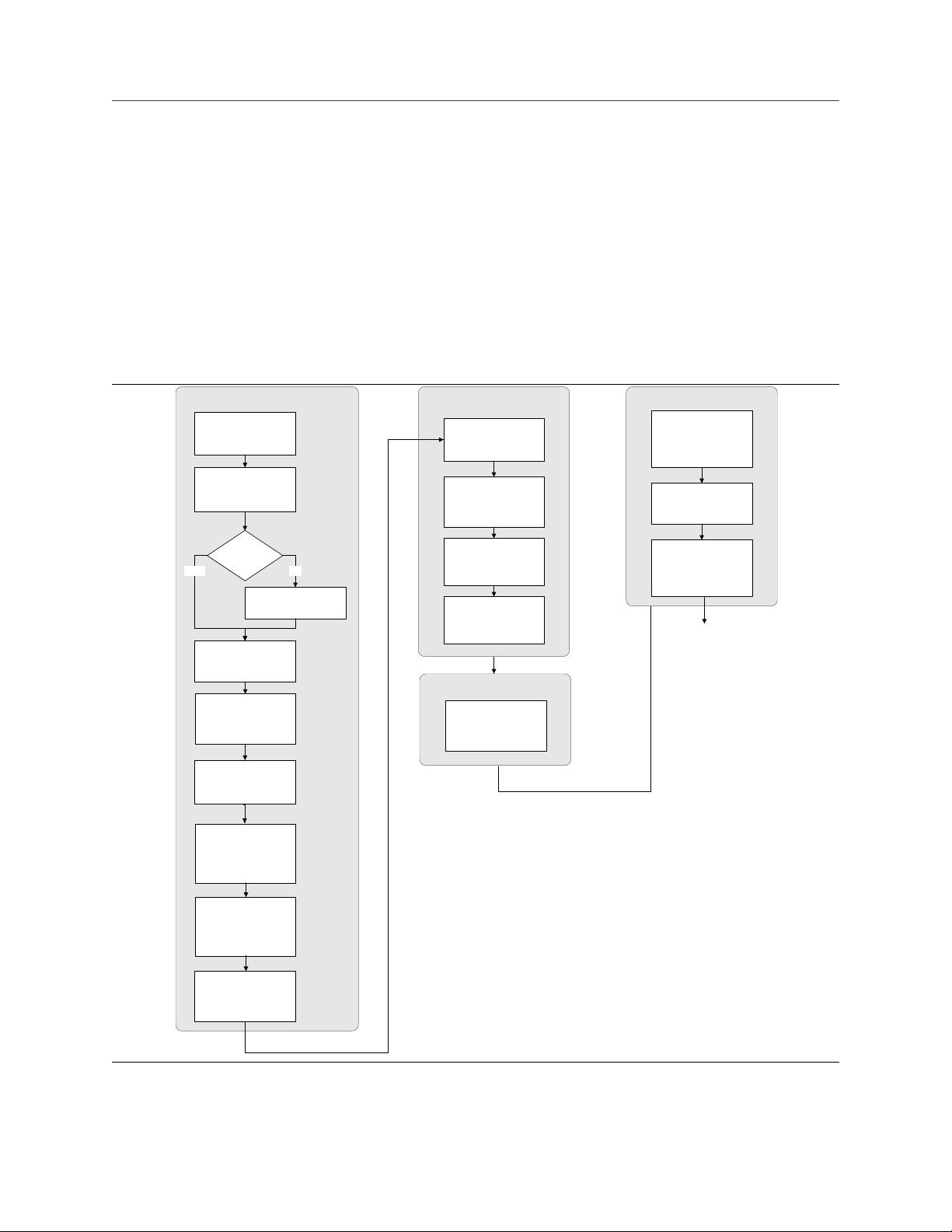
3.1
Configuration flowchart
Use the following flowchart as a general guide to the configuration and commissioning process.
Some options may not apply to your installation. Detailed information is provided in the remainder of this
manual.
Configure process measurement
Configure mass flow
measurement
Configure volume flow
meaurement
Volume flow type
Liquid
Configure flow direction
Configure density
measurement
Gas
Define gas properties
Configure device options and preferences
Configure display
parameters
Configure fault handling
parameters
Configure sensor
parameters
Configure device
parameters
Integrate device with control system
Configure digital
communications
Test and move to production
Test or tune transmitter
using sensor simulation
Back up transmitter
configuration
Enable write-protection on
transmitter configuration
Done
Configure temperature
measurement
Configure petroleum
measurement (API)
application (if available)
Configure concentration
measurement application (if
available)
Configure pressure
compensation (optional)
Configuration and Use Manual 13

Introduction to configuration and commissioning Configuration and Use Manual
August 2022 20000326
3.2 Default values and ranges
See Default values and ranges to view the default values and ranges for the most commonly used parameters.
3.3
Display OFF-LINE MAINT → OFF-LINE CONFG
ProLink III Device Tools → Configuration → Transmitter Display → Display Security
Field Communicator Configure → Manual Setup → Display → Display Menu → Offline Menu
Fieldbus host LDO TB → EN_LDO_OFFLINE_MENU (OD Index 17)
By default, access to the off-line menu of the display is enabled. If it is disabled, you must enable it if you want
to use the display to configure the transmitter.
Restriction
You cannot use the display to enable access to the off-line menu. You must make a connection from another
tool.
Enable access to the off-line menu of the display
3.4 Disable write-protection on the transmitter
configuration
ProLink III Device Tools → Configuration → Write-Protection
Fieldbus Communicator Service Tools → Maintenance → Security and Simulation → Write Lock Setup
If the transmitter is write-protected, the configuration is locked and you must unlock it before you can change
any configuration parameters. By default, the transmitter is not write-protected.
Tip
Write-protecting the transmitter prevents accidental changes to configuration. It does not prevent normal
operational use. You can always disable write-protection, perform any required configuration changes, then
re-enable write-protection.
3.5 Place function, transducer, and resource blocks in
OOS mode
Prerequisites
Before you modify parameters on the fieldbus function blocks, you must place the function blocks in OOS
mode.
Procedure
Option Description
Display Not available
14 Micro Motion 2700 Transmitters with FOUNDATION Fieldbus

Configuration and Use Manual Introduction to configuration and commissioning
20000326 August 2022
Option Description
ProLink III Device Tools → Configuration → Communications → Fieldbus
Field Communicator Overview → Mode
Fieldbus host (block name) → MODE_BLOCK (OD Index Number 005)
Postrequisites
Before you return the device to operation, you must place them back in service (Auto mode).
3.6
If you plan to use a fieldbus connection to configure the device, you can lock out fieldbus hosts. If you do this,
the fieldbus hosts will be able to read data from the device, but you will not be able to write data to the
device.
Restriction
This feature is available only if you are using the Field Communicator or AMS.
Procedure
Choose Service Tools → Maintenance → Security and Simulation → Write Lock Setup.
3.7
Display Not available
ProLink III Device Tools → Configuration Transfer → Restore Factory Configuration
Field communicator Service Tools → Maintenance → Reset/Restore → Master Reset
Fieldbus host Diagnostic TB → Restore Factory Config (OD Index 056)
Restoring the factory configuration returns the transmitter to the same configuration it had when it left the
factory. This may be useful if you experience problems during configuration.
Important
You cannot restore factory configurations with a 700 core.
Lockout FOUNDATION Fieldbus hosts
Restore the factory configuration
Tip
Restoring the factory configuration is not a common action. You may want to contact customer support to
see if there is a preferred method to resolve any issues.
3.8 Enable or disable fieldbus write lock
When locked, the fieldbus write lock prevents any configuration changes being written from the fieldbus
segment.
Procedure
Set the Write Lock parameter (OD index 34) of the Resource block to Locked (1) or Unlocked (0).
Configuration and Use Manual 15

Introduction to configuration and commissioning Configuration and Use Manual
August 2022 20000326
16 Micro Motion 2700 Transmitters with FOUNDATION Fieldbus

Configuration and Use Manual Configure process measurement
20000326 August 2022
4 Configure process measurement
4.1
The mass flow measurement parameters control how mass flow is measured and reported.
Configure mass flow measurement
4.1.1 Configure Mass Flow Measurement Unit
Display OFF-LINE MAINT → OFF-LINE CONFG → UNITS → MASS
ProLink III Device Tools → Configuration → Process Measurement → Flow
Field Communicator Configure → Manual Setup → Measurements → Flow → Mass Flow Unit
Fieldbus host Measurement TB → MFLOW_UNITS (OD Index 15)
Mass Flow Measurement Unit specifies the unit of measure that will be used for the mass flow rate. The unit
used for mass total and mass inventory is derived from this unit.
Procedure
Set Mass Flow Measurement Unit to the unit you want to use.
The default setting for Mass Flow Measurement Unit is g/sec (grams per second).
Tip
If the measurement unit you want to use is not available, you can define a special measurement unit.
Options for Mass Flow Measurement Unit
The transmitter provides a standard set of measurement units for Mass Flow Measurement Unit, plus one
user-defined special measurement unit. Different communications tools may use different labels for the
units.
Label
Unit description
Grams per second G/S g/sec g/s
Grams per minute G/MIN g/min g/min
Grams per hour G/H g/hr g/h
Kilograms per second KG/S kg/sec kg/s
Kilograms per minute KG/MIN kg/min kg/min
Kilograms per hour KG/H kg/hr kg/h
Kilograms per day KG/D kg/day kg/d
Metric tons per minute T/MIN mTon/min t/min
Metric tons per hour T/H mTon/hr t/h
Metric tons per day T/D mTon/day t/d
Pounds per second LB/S lbs/sec lb/s
Display ProLink III Field Communicator
Configuration and Use Manual 17

Configure process measurement Configuration and Use Manual
August 2022 20000326
Label
Unit description
Pounds per minute LB/MIN lbs/min lb/min
Pounds per hour LB/H lbs/hr lb/h
Pounds per day LB/D lbs/day lb/d
Short tons (2000 pounds) per minute ST/MIN sTon/min STon/min
Short tons (2000 pounds) per hour ST/H sTon/hr STon/h
Short tons (2000 pounds) per day ST/D sTon/day STon/d
Long tons (2240 pounds) per hour LT/H lTon/hr LTon/h
Long tons (2240 pounds) per day LT/D lTon/day LTon/d
Special unit SPECL special Special
Display ProLink III Field Communicator
Define a special measurement unit for mass flow
Display Not available
ProLink III Device Tools → Configuration → Process Measurement → Flow → Special Units
Field Communicator Configure → Manual Setup → Measurements → Special Units → Mass Special Units
Fieldbus host
Measurement TB → MFLOW_SPECIAL_UNIT_BASE (OD Index 16)
Measurement TB → MFLOW_SPECIAL_UNIT_TIME (OD Index 17)
Measurement TB → MFLOW_SPECIAL_UNIT_CONV (OD Index 18)
Measurement TB → MFLOW_SPECIAL_UNIT_STR (OD Index 19)
A special measurement unit is a user-defined unit of measure that allows you to report process data, totalizer
data, and inventory data in a unit that is not available in the transmitter. A special measurement unit is
calculated from an existing measurement unit using a conversion factor.
Note
Although you cannot define a special measurement unit using the display, you can use the display to select an
existing special measurement unit, and to view process data using the special measurement unit.
The special unit label displays only on the local display. The AI block uses and displays the actual engineering
unit (i.e. lb/min).
Procedure
1. Specify Base Mass Unit.
Base Mass Unit is the existing mass unit that the special unit will be based on.
2. Specify Base Time Unit.
Base Time Unit is the existing time unit that the special unit will be based on.
3. Calculate Mass Flow Conversion Factor as follows:
a) x base units = y special units
b) Mass Flow Conversion Factor = x ÷ y
18 Micro Motion 2700 Transmitters with FOUNDATION Fieldbus

Configuration and Use Manual Configure process measurement
20000326 August 2022
The original mass flow rate value is divided by this value.
4.
Enter Mass Flow Conversion Factor.
5. Set Mass Flow Label to the name you want to use for the mass flow unit.
6. Set Mass Total Label to the name you want to use for the mass total and mass inventory unit.
The special measurement unit is stored in the transmitter. You can configure the transmitter to use the
special measurement unit at any time.
Example: Defining a special measurement unit for mass flow
You want to measure mass flow in ounces per second (oz/sec).
1. Set Base Mass Unit to Pounds (lb).
2. Set Base Time Unit to Seconds (sec).
3. Calculate Mass Flow Conversion Factor:
a. 1 lb/sec = 16 oz/sec
b. Mass Flow Conversion Factor = 1 ÷ 16 = 0.0625
4. Set Mass Flow Conversion Factor to 0.0625.
5. Set Mass Flow Label to oz/sec.
6. Set Mass Total Label to oz.
4.1.2 Configure Flow Damping
Display Not available
ProLink III Device Tools → Configuration → Process Measurement → Flow
Field Communicator Configure → Manual Setup → Measurements → Flow → Flow Damping
Fieldbus host Measurement TB → FLOW_DAMPING → OD Index
Damping is used to smooth out small, rapid fluctuations in process measurement. Damping Value specifies
the time period (in seconds) over which the transmitter will spread changes in the process variable. At the end
of the interval, the internal value will reflect 63% of the change in the actual measured value.
Procedure
Set Flow Damping to the value you want to use.
• Default: 0.8 seconds
• Range: 0 seconds to 51.2 seconds
• Valid damping values: 0.0, 0.1, 0.2, 0.4, 0.8, 1.6, 3.2, 6.4, 12.8, 25.6, 51.2
Tip
• A high damping value makes the process variable appear smoother because the reported value changes
slowly.
• A low damping value makes the process variable appear more erratic because the reported value changes
more quickly.
Configuration and Use Manual 19

Configure process measurement Configuration and Use Manual
August 2022 20000326
• The combination of a high damping value and rapid, large changes in flow rate can result in increased
measurement error.
• Whenever the damping value is non-zero, the reported measurement will lag the actual measurement
because the reported value is being averaged over time.
• In general, lower damping values are preferable because there is less chance of data loss, and less lag time
between the actual measurement and the reported value.
The value you enter is automatically rounded off to the nearest valid value. For example, if the damping is
currently set to 0.8 seconds, any value entered up to 1.2 seconds will be rounded down to 0.8 seconds, and
any value entered from 1.21 to 1.59 seconds will be rounded up to 1.6 seconds.
Effect of flow damping on volume measurement
Flow damping affects volume measurement for liquid volume data. Flow damping also affects volume
measurement for gas standard volume data. The transmitter calculates volume data from the damped mass
flow data.
4.1.3
Display Not available
ProLink III Device Tools → Configuration → Process Measurement → Flow
Field Communicator Configure → Manual Setup → Measurements → Flow → Mass Flow Cutoff
Fieldbus host Measurement TB → MASS_LOW_CUT (OD Index 38)
Mass Flow Cutoff specifies the lowest mass flow rate that will be reported as measured. All mass flow rates
below this cutoff will be reported as 0.
Procedure
Set Mass Flow Cutoff to the value you want to use.
The default value for Mass Flow Cutoff is 0.0 g/sec or a sensor-specific value set at the factory. The
recommended value is 0.5% of the nominal flow rate of the attached sensor. See the sensor specifications. Do
not leave Mass Flow Cutoff at 0.0 g/sec.
Configure Mass Flow Cutoff
Effect of Mass Flow Cutoff on volume measurement
Mass Flow Cutoff does not affect volume measurement. Volume data is calculated from the actual mass data
rather than the reported value.
Volume flow has a separate Volume Flow Cutoff that is not affected by the Mass Flow Cutoff value.
20 Micro Motion 2700 Transmitters with FOUNDATION Fieldbus

Configuration and Use Manual Configure process measurement
20000326 August 2022
4.2 Configure volume flow measurement for liquid
applications
The volume flow measurement parameters control how liquid volume flow is measured and reported.
Restriction
You cannot implement both liquid volume flow and gas standard volume flow at the same time. Choose one
or the other.
4.2.1 Configure Volume Flow Type for liquid applications
Display Not available
ProLink III Device Tools → Configuration → Process Measurement → Flow
Field Communicator Configure → Manual Setup → Measurements → GSV → Volume Flow Type → Liquid
Fieldbus host Measurement TB → SNS_EnableGSV (OD Index 66)
Volume Flow Type controls whether liquid or gas standard volume flow measurement will be used.
Restriction
Gas standard volume measurement is incompatible with some applications. Set Volume Flow Type to Liquid
if you are using any of the following applications:
• Petroleum measurement
• Concentration measurement
Procedure
Set Volume Flow Type to Liquid.
4.2.2
Configure Volume Flow Measurement Unit for liquid
applications
Display OFF-LINE MAINT → OFF-LINE CONFG → UNITS → VOL
ProLink III Device Tools → Configuration → Process Measurement → Flow
Field Communicator Configure → Manual Setup → Measurements → Flow → Volume Flow Unit
Fieldbus host Measurement TB → VOLUME_FLOW_UNITS (OD Index 25)
Volume Flow Measurement Unit specifies the unit of measurement that will be displayed for the volume
flow rate. The unit used for the volume total and volume inventory is based on this unit.
Prerequisites
Before you configure Volume Flow Measurement Unit, be sure that Volume Flow Type is set to Liquid.
Procedure
Set Volume Flow Measurement Unit to the unit you want to use.
Configuration and Use Manual 21

Configure process measurement Configuration and Use Manual
August 2022 20000326
To read US gallons, select that unit from this menu. G/MIN stands for grams per minute (USGPM), not gallons
per minute. The default setting for Volume Flow Measurement Unit is l/sec (liters per second).
Tip
If the measurement unit you want to use is not available, you can define a special measurement unit.
Options for Volume Flow Measurement Unit for liquid applications
The transmitter provides a standard set of measurement units for Volume Flow Measurement Unit, plus one
user-defined measurement unit. Different communications tools may use different labels for the units.
Label
Unit description
Cubic feet per second CUFT/S ft3/sec CFS
Cubic feet per minute CUF/MN ft3/min CFM
Cubic feet per hour CUFT/H ft3/hr CFH
Cubic feet per day CUFT/D ft3/day ft3/d
Cubic meters per second M3/S m3/sec m3/s
Cubic meters per minute M3/MIN m3/min m3/min
Cubic meters per hour M3/H m3/hr m3/h
Cubic meters per day M3/D m3/day m3/d
U.S. gallons per second USGPS US gal/sec gal/s
U.S. gallons per minute USGPM US gal/min GPM
U.S. gallons per hour USGPH US gal/hr gal/h
U.S. gallons per day USGPD US gal/day gal/d
Million U.S. gallons per day MILG/D mil US gal/day Mgal/d
Liters per second L/S l/sec L/s
Liters per minute L/MIN l/min L/min
Liters per hour L/H l/hr L/h
Display ProLink III Field Communicator
Million liters per day MILL/D mil l/day ML/d
Imperial gallons per second UKGPS Imp gal/sec Impgal/s
Imperial gallons per minute UKGPM Imp gal/min Impgal/min
Imperial gallons per hour UKGPH Imp gal/hr Impgal/h
Imperial gallons per day UKGPD Imp gal/day Impgal/d
Barrels per second
Barrels per minute BBL/MN barrels/min barrel(US Beer)/min
Barrels per hour BBL/H barrels/hr barrel(US Beer)/h
Barrels per day BBL/D barrels/day barrel(US Beer)/d
Beer barrels per second
22 Micro Motion 2700 Transmitters with FOUNDATION Fieldbus
(1)
(2)
BBL/S barrels/sec barrel(US Beer)/s
BBBL/S Beer barrels/sec bbbl/s

Configuration and Use Manual Configure process measurement
20000326 August 2022
Label
Unit description
Beer barrels per minute BBBL/MN Beer barrels/min bbbl/min
Beer barrels per hour BBBL/H Beer barrels/hr bbbl/h
Beer barrels per day BBBL/D Beer barrels/day bbbl/d
(1) Unit based on oil barrels (42 U.S. gallons).
(2) Unit based on U.S. beer barrels (31 U.S. gallons).
Display ProLink III Field Communicator
Define a special measurement unit for volume flow
Display Not available
ProLink III Device Tools → Configuration → Process Measurement → Flow → Special Units
Field Communicator Configure → Manual Setup → Measurements → Special Units → Volume Special Units
Fieldbus host
A special measurement unit is a user-defined unit of measure that allows you to report process data, totalizer
data, and inventory data in a unit that is not available in the transmitter. A special measurement unit is
calculated from an existing measurement unit using a conversion factor.
Note
Although you cannot define a special measurement unit using the display, you can use the display to select an
existing special measurement unit, and to view process data using the special measurement unit.
The special unit label displays only on the local display. The AI block uses and displays the actual engineering
unit (i.e. L/min).
Measurement TB → VOL_SPECIAL_UNIT_BASE (OD Index 26)
Measurement TB → VOL _SPECIAL_UNIT_TIME (OD Index 27)
Measurement TB → VOL _SPECIAL_UNIT_CONV (OD Index 28)
Measurement TB → VOL _SPECIAL_UNIT_STR (OD Index 29)
Procedure
1. Specify Base Volume Unit.
Base Volume Unit is the existing volume unit that the special unit will be based on.
2. Specify Base Time Unit.
Base Time Unit is the existing time unit that the special unit will be based on.
3. Calculate Volume Flow Conversion Factor as follows:
a) x base units = y special units
b) Volume Flow Conversion Factor = x ÷ y
4. Enter Volume Flow Conversion Factor.
The original volume flow rate value is divided by this conversion factor.
5. Set Volume Flow Label to the name you want to use for the volume flow unit.
6. Set Volume Total Label to the name you want to use for the volume total and volume inventory unit.
Configuration and Use Manual 23

Configure process measurement Configuration and Use Manual
August 2022 20000326
The special measurement unit is stored in the transmitter. You can configure the transmitter to use the
special measurement unit at any time.
Defining a special measurement unit for volume flow
You want to measure volume flow in pints per second (pints/sec).
1.
Set Base Volume Unit to Gallons (gal).
2. Set Base Time Unit to Seconds (sec).
3. Calculate the conversion factor:
a. 1 gal/sec = 8 pints/sec
b. Volume Flow Conversion Factor = 1 ÷ 8 = 0.1250
4. Set Volume Flow Conversion Factor to 0.1250.
5. Set Volume Flow Label to pints/sec.
6. Set Volume Total Label to pints.
4.2.3 Configure Volume Flow Cutoff
Display Not available
ProLink III Device Tools → Configuration → Process Measurement → Flow
Field Communicator Configure → Manual Setup → Measurements → Flow → Volume Flow Cutoff
Fieldbus host Measurement TB → VOLUME_FLOW_LOW_CUTOFF (OD Index 39)
Volume Flow Cutoff specifies the lowest volume flow rate that will be reported as measured. All volume flow
rates below this cutoff are reported as 0.
Procedure
Set Volume Flow Cutoff to the value you want to use.
The default value for Volume Flow Cutoff is 0.0 l/sec (liters per second). The lower limit is 0. Leaving the
volume flow cutoff at 0 is not recommended.
4.3
The gas standard volume (GSV) flow measurement parameters control how volume flow is measured and
reported in a gas application.
Restriction
You cannot implement both liquid volume flow and gas standard volume flow at the same time. Choose one
or the other.
Configure GSV flow measurement
4.3.1 Configure Volume Flow Type for gas applications
Display Not available
ProLink III Device Tools → Configuration → Process Measurement → Flow
24 Micro Motion 2700 Transmitters with FOUNDATION Fieldbus

Configuration and Use Manual Configure process measurement
20000326 August 2022
Field Communicator Configure → Manual Setup → Measurements → GSV → Volume Flow Type → Standard Gas Volume
Fieldbus host
Measurement TB → GSV_Gas_Dens (OD Index 62)
Measurement TB → SNS_GSV_FlowUnits (OD Index 67)
Measurement TB → SNS_GSVflowFactor (OD Index 71)
Measurement TB → SNS_GSV_FlowCutoff (OD Index 74)
Volume Flow Type controls whether liquid or gas standard volume flow measurement is used.
Restriction
Gas standard volume measurement is incompatible with some applications. Set Volume Flow Type to Liquid
if you are using any of the following applications:
• Petroleum measurement
• Concentration measurement
Procedure
Set Volume Flow Type to Gas Standard Volume.
4.3.2
Display Not available
ProLink III Device Tools → Configuration → Process Measurement → Flow
Field Communicator Configure → Manual Setup → Measurements → GSV → Gas Ref Density
Fieldbus host Measurement TB → GSV_Gas_Dens (OD Index 62)
Configure Standard Density of Gas
The Standard Density of Gas value is the gas density at standard reference conditions. Use it to convert the
measured mass flow data to volume flow at reference conditions.
Prerequisites
Ensure that Density Measurement Unit is set to the measurement unit you want to use for Standard Density
of Gas.
Procedure
Set Standard Density of Gas to standard reference conditions.
4.3.3
Display OFF-LINE MAINT → OFF-LINE CONFG → UNITS → GSV
ProLink III Device Tools → Configuration → Process Measurement → Flow
Field Communicator Configure → Manual Setup → Measurements → GSV → GSV Flow Unit
Fieldbus host Measurement TB → SNS_GSV_FlowUnits (OD Index 67)
Configure Gas Standard Volume Flow Unit
Configuration and Use Manual 25

Configure process measurement Configuration and Use Manual
August 2022 20000326
Gas Standard Volume Flow Unit specifies the unit of measure that will be displayed for the gas standard
volume flow. The measurement unit used for the gas volume total and the gas volume inventory is derived
from this unit.
Prerequisites
Before you configure Gas Standard Volume Flow Unit, be sure that Volume Flow Type is set to Gas Standard
Volume.
Procedure
Set Gas Standard Volume Flow Unit to the unit you want to use.
The default setting for Gas Standard Volume Flow Unit is SCFM (Standard Cubic Feet per Minute).
Tip
If the measurement unit you want to use is not available, you can define a special measurement unit.
Options for Gas Standard Volume Flow Unit
The transmitter provides a standard set of measurement units for Gas Standard Volume Flow Unit, plus one
user-defined special measurement unit. Different communications tools may use different labels for the
units.
Label
Unit description
Normal cubic meters per second NM3/S Nm3/sec Nm3/s
Normal cubic meters per minute NM3/MN Nm3/sec Nm3/min
Normal cubic meters per hour NM3/H Nm3/hr Nm3/h
Normal cubic meters per day NM3/D Nm3/day Nm3/d
Normal liters per second NLPS NLPS NL/s
Normal liters per minute NLPM NLPM NL/min
Normal liters per hour NLPH NLPH NL/h
Normal liters per day NLPD NLPD NL/d
Standard cubic feet per second SCFS SCFS SCFS
Standard cubic feet per minute SCFM SCFM SCFM
Standard cubic feet per hour SCFH SCFH SCFH
Standard cubic feet per day SCFD SCFD SCFD
Standard cubic meters per second SM3/S Sm3/sec Sm3/s
Standard cubic meters per minute SM3/MN Sm3/min Sm3/min
Standard cubic meters per hour SM3/H Sm3/hr Sm3/h
Display ProLink III Field Communicator
Standard cubic meters per day SM3/D Sm3/day Sm3/d
Standard liters per second SLPS SLPS SL/s
Standard liters per minute SLPM SLPM SL/min
Standard liters per hour SLPH SLPH SL/h
26 Micro Motion 2700 Transmitters with FOUNDATION Fieldbus

Configuration and Use Manual Configure process measurement
20000326 August 2022
Label
Unit description
Standard liters per day SLPD SLPD SL/d
Special measurement unit SPECL special Special
Display ProLink III Field Communicator
Define a special measurement unit for gas standard volume flow
Display Not available
ProLink III Device Tools → Configuration → Process Measurement → Flow → Special Units
Field Communicator Configure → Manual Setup → Measurements → Special Units → Special GSV Units
Fieldbus host
A special measurement unit is a user-defined unit of measure that allows you to report process data, totalizer
data, and inventory data in a unit that is not available in the transmitter. A special measurement unit is
calculated from an existing measurement unit using a conversion factor.
Note
Although you cannot define a special measurement unit using the display, you can use the display to select an
existing special measurement unit, and to view process data using the special measurement unit.
The special unit label displays only on the local display. The AI block uses and displays the actual engineering
unit (i.e. SCFM).
Measurement TB → SNS_GSVflowBaseUnit (OD Index 69)
Measurement TB → SNS_GSVflowBaseTime (OD Index 70)
Measurement TB → SNS_GSVflowFactor (OD Index 71)
Measurement TB → SNS_GSVflowText (OD Index 72)
Procedure
1. Specify Base Gas Standard Volume Unit.
Base Gas Standard Volume Unit is the existing gas standard volume unit that the special unit will be
based on.
2. Specify Base Time Unit.
Base Time Unit is the existing time unit that the special unit will be based on.
3. Calculate Gas Standard Volume Flow Conversion Factor as follows:
a) x base units = y special units
b) Gas Standard Volume Flow Conversion Factor = x ÷ y
4. Enter the Gas Standard Volume Flow Conversion Factor.
The original gas standard volume flow value is divided by this conversion factor.
5. Set Gas Standard Volume Flow Label to the name you want to use for the gas standard volume flow
unit.
6. Set Gas Standard Volume Total Label to the name you want to use for the gas standard volume total
and gas standard volume inventory unit.
The special measurement unit is stored in the transmitter. You can configure the transmitter to use the
special measurement unit at any time.
Configuration and Use Manual 27

Configure process measurement Configuration and Use Manual
August 2022 20000326
Example: Defining a special measurement unit for gas standard volume flow
You want to measure gas standard volume flow in thousands of standard cubic feet per minute.
1.
Set Base Gas Standard Volume Unit to SCF.
2. Set Base Time Unit to minutes (min).
3. Calculate the conversion factor:
a. 1 thousands of standard cubic feet per minute = 1000 cubic feet per minute
b. Gas Standard Volume Flow Conversion Factor = 1 ÷ 1000 = 0.001 standard
4. Set Gas Standard Volume Flow Conversion Factor to 0.001.
5. Set Gas Standard Volume Flow Label to MSCFM.
6. Set Gas Standard Volume Total Label to MSCF.
4.3.4 Configure Gas Standard Volume Flow Cutoff
Display Not available
ProLink III Device Tools → Configuration → Process Measurement → Flow
Field Communicator Configure → Manual Setup → Measurements → GSV → GSV Cutoff
Fieldbus host Measurement TB → SNS_GSV_FlowCutoff (OD Index 74)
Gas Standard Volume Flow Cutoff specifies the lowest gas standard volume flow rate that will reported as
measured. All gas standard volume flow rates below this cutoff will be reported as 0.
Procedure
Set Gas Standard Volume Flow Cutoff to the value you want to use.
The default value for Gas Standard Volume Flow Cutoff is 0.0. The lower limit is 0.0. There is no upper limit.
The recommended value is 0.5% of the nominal flow rate of the attached sensor. See the sensor
specifications.
4.4
Display Not available
ProLink III Device Tools → Configuration → Process Measurement → Flow
Field Communicator Configure → Manual Setup → Measurements → Flow → Flow Direction
Fieldbus host Measurement TB → FLOW_DIRECTION {OD Index 41)
Flow Direction controls how forward flow and reverse flow affect flow measurement and reporting.
Flow Direction is defined with respect to the flow arrow on the sensor:
• Forward flow (positive flow) moves in the direction of the flow arrow on the sensor.
• Reverse flow (negative flow) moves in the direction opposite to the flow arrow on the sensor.
Configure Flow Direction
28 Micro Motion 2700 Transmitters with FOUNDATION Fieldbus

Configuration and Use Manual Configure process measurement
20000326 August 2022
Tip
Micro Motion sensors are bidirectional. Measurement accuracy is not affected by actual flow direction or the
setting of the Flow Direction parameter.
Procedure
Set Flow Direction to the value you want to use.
4.4.1
Forward Forward Appropriate when the Flow Direction arrow is in
Reverse Reverse Appropriate when the Flow Direction arrow is in
Absolute Value Absolute Value Flow Direction arrow is not relevant.
Bidirectional Bi directional Appropriate when both forward and reverse flow
Negate Forward Negate/Forward Only Appropriate when the Flow Direction arrow is in
Negate Bidirectional Negate/Bi-directional Appropriate when both forward and reverse flow
Options for Flow Direction
Flow Direction setting
Relationship to Flow Direction arrow on sensorProLink III Field Communicator
the same direction as the majority of flow.
the opposite direction from the majority of flow.
are expected, and forward flow will dominate, but
the amount of reverse flow will be significant.
the opposite direction from the majority of flow.
are expected, and reverse flow will dominate, but
the amount of forward flow will be significant.
Effect of flow direction on digital communications
Flow direction affects how flow values are reported via digital communications. The following table describes
the effect of the flow direction parameter and actual flow direction on flow values reported via digital
communications.
Table 4-1: Effect of the flow direction on flow values
Actual flow direction
Flow Direction setting
Forward Positive 0 Negative
Reverse Positive 0 Negative
Bidirectional Positive 0 Negative
Absolute Value Positive
Negate Forward Negative 0 Positive
Negate Bidirectional Negative 0 Positive
(1) Refer to the digital communications status bits for an indication of whether flow is positive or negative.
Configuration and Use Manual 29
Forward Zero flow Reverse
(1)
0 Positive
(1)

Configure process measurement Configuration and Use Manual
August 2022 20000326
Effect of flow direction on flow totals
Flow direction affects how flow totals and inventories are calculated.
Actual flow direction
Flow Direction setting
Forward Totals increase Totals do not change Totals do not change
Bidirectional Totals increase Totals do not change Totals decrease
Negate Forward Totals do not change Totals do not change Totals increase
Negate Bidirectional Totals decrease Totals do not change Totals increase
Forward Zero flow Reverse
4.5 Configure density measurement
The density measurement parameters control how density is measured and reported.
4.5.1
Display OFF-LINE MAINT → OFF-LINE CONFG → UNITS → DENS
ProLink III Device Tools → Configuration → Process Measurement → Density
Field Communicator Configure → Manual Setup → Measurements → Density → Density Unit
Fieldbus host Measurement TB → DENSITY_UNITS (OD Index 23)
Density Measurement Unit controls the measurement units that will be used in density calculations and
reporting.
Procedure
Configure Density Measurement Unit
Set Density Measurement Unit to the option you want to use.
The default setting for Density Measurement Unit is g/cm3 (grams per cubic centimeter).
Options for Density Measurement Unit
The transmitter provides a standard set of measurement units for Density Measurement Unit. Different
communications tools may use different labels.
Label
Unit description
Specific gravity
Grams per cubic centimeter G/CM3 g/cm3 g/cm3
Grams per liter G/L g/l g/L
Grams per milliliter G/mL g/ml g/ml
Kilograms per liter KG/L kg/l kg/L
Kilograms per cubic meter KG/M3 kg/m3 kg/m3
Pounds per U.S. gallon LB/GAL lbs/Usgal lb/gal
30 Micro Motion 2700 Transmitters with FOUNDATION Fieldbus
(1)
Display ProLink III Field Communicator
SGU SGU SGU
 Loading...