


Configuration and Use Manual
P/N 20002983, Rev. A
October 2005
Micro Motion
®
Model 3711
Gas Flow Computers
Configuration and Use Manual

©2005, Micro Motion, Inc. All rights reserved. ELITE, ProLink, and the Micro Motion logo are registered trademarks of Micro
Motion, Inc., Boulder, Colorado. MVD and MVD Direct Connect are trademarks of Micro Motion., Inc., Boulder, Colorado. Micro
Motion is a registered trade name of Micro Motion, Inc., Boulder, Colorado. The Emerson logo is a trademark of Emerson Electric
Co. All other trademarks are property of their respective owners.

Contents
Chapter 1 Before You Begin . . . . . . . . . . . . . . . . . . . . . . . . . . . . . . . . . . . . . 1
1.1 Overview . . . . . . . . . . . . . . . . . . . . . . . . . . . . . . . . . . . . . . . . . . . . . . . . . . . . . . . . . . . 1
1.2 Safety . . . . . . . . . . . . . . . . . . . . . . . . . . . . . . . . . . . . . . . . . . . . . . . . . . . . . . . . . . . . . 1
1.3 About the Model 3711 Gas Flow Computer . . . . . . . . . . . . . . . . . . . . . . . . . . . . . . . . 1
1.3.1 Model 3711 system components . . . . . . . . . . . . . . . . . . . . . . . . . . . . . . . . 1
1.3.2 User programs . . . . . . . . . . . . . . . . . . . . . . . . . . . . . . . . . . . . . . . . . . . . . . 1
1.3.3 Implementation overview . . . . . . . . . . . . . . . . . . . . . . . . . . . . . . . . . . . . . . 2
1.4 Communication tools. . . . . . . . . . . . . . . . . . . . . . . . . . . . . . . . . . . . . . . . . . . . . . . . . . 2
1.5 Model 3711 configuration overview. . . . . . . . . . . . . . . . . . . . . . . . . . . . . . . . . . . . . . . 2
1.5.1 Quick start . . . . . . . . . . . . . . . . . . . . . . . . . . . . . . . . . . . . . . . . . . . . . . . . . 2
1.5.2 Basic configuration. . . . . . . . . . . . . . . . . . . . . . . . . . . . . . . . . . . . . . . . . . . 3
1.5.3 Advanced options . . . . . . . . . . . . . . . . . . . . . . . . . . . . . . . . . . . . . . . . . . . 3
1.6 Model 3711 administration overview . . . . . . . . . . . . . . . . . . . . . . . . . . . . . . . . . . . . . . 4
1.7 Documentation resources . . . . . . . . . . . . . . . . . . . . . . . . . . . . . . . . . . . . . . . . . . . . . . 4
1.8 Micro Motion customer service . . . . . . . . . . . . . . . . . . . . . . . . . . . . . . . . . . . . . . . . . . 4
Chapter 2 Getting Started. . . . . . . . . . . . . . . . . . . . . . . . . . . . . . . . . . . . . . . 5
2.1 Overview . . . . . . . . . . . . . . . . . . . . . . . . . . . . . . . . . . . . . . . . . . . . . . . . . . . . . . . . . . . 5
2.2 Starting the Model 3711 . . . . . . . . . . . . . . . . . . . . . . . . . . . . . . . . . . . . . . . . . . . . . . . 5
2.3 Installing ROCLINK 800 . . . . . . . . . . . . . . . . . . . . . . . . . . . . . . . . . . . . . . . . . . . . . . . 6
2.3.1 PC requirements for ROCLINK 800 . . . . . . . . . . . . . . . . . . . . . . . . . . . . . . 6
2.3.2 Installing ROCLINK 800. . . . . . . . . . . . . . . . . . . . . . . . . . . . . . . . . . . . . . . 6
2.4 Using ROCLINK 800 . . . . . . . . . . . . . . . . . . . . . . . . . . . . . . . . . . . . . . . . . . . . . . . . . . 7
2.4.1 Starting ROCLINK 800 . . . . . . . . . . . . . . . . . . . . . . . . . . . . . . . . . . . . . . . 7
2.4.2 ROCLINK 800 user interface . . . . . . . . . . . . . . . . . . . . . . . . . . . . . . . . . . . 7
2.4.3 TLP system . . . . . . . . . . . . . . . . . . . . . . . . . . . . . . . . . . . . . . . . . . . . . . . 10
2.5 Configuration files . . . . . . . . . . . . . . . . . . . . . . . . . . . . . . . . . . . . . . . . . . . . . . . . . . . 11
2.5.1 Managing device configuration files . . . . . . . . . . . . . . . . . . . . . . . . . . . . . 11
2.5.2 Creating a new device configuration file . . . . . . . . . . . . . . . . . . . . . . . . . 11
2.5.3 Device configuration backup and duplication. . . . . . . . . . . . . . . . . . . . . . 13
2.6 Setting up devices and groups . . . . . . . . . . . . . . . . . . . . . . . . . . . . . . . . . . . . . . . . . 13
2.7 First connection to the Model 3711 . . . . . . . . . . . . . . . . . . . . . . . . . . . . . . . . . . . . . . 13
2.7.1 Disconnecting and closing . . . . . . . . . . . . . . . . . . . . . . . . . . . . . . . . . . . . 14
Chapter 3 System Configuration . . . . . . . . . . . . . . . . . . . . . . . . . . . . . . . . . 15
3.1 Overview . . . . . . . . . . . . . . . . . . . . . . . . . . . . . . . . . . . . . . . . . . . . . . . . . . . . . . . . . . 15
3.2 Setting the Model 3711 clock . . . . . . . . . . . . . . . . . . . . . . . . . . . . . . . . . . . . . . . . . . 15
3.3 Configuring security . . . . . . . . . . . . . . . . . . . . . . . . . . . . . . . . . . . . . . . . . . . . . . . . . 16
3.3.1 ROCLINK 800 security. . . . . . . . . . . . . . . . . . . . . . . . . . . . . . . . . . . . . . . 16
3.3.2 Device security. . . . . . . . . . . . . . . . . . . . . . . . . . . . . . . . . . . . . . . . . . . . . 17
3.3.3 Access level . . . . . . . . . . . . . . . . . . . . . . . . . . . . . . . . . . . . . . . . . . . . . . . 19
3.4 Configuring Model 3711 device information . . . . . . . . . . . . . . . . . . . . . . . . . . . . . . . 21
3.5 Configuring display options . . . . . . . . . . . . . . . . . . . . . . . . . . . . . . . . . . . . . . . . . . . . 23
Configuration and Use Manual i

Contents
Chapter 4 Setting Up Communications. . . . . . . . . . . . . . . . . . . . . . . . . . . . . 25
4.1 Overview . . . . . . . . . . . . . . . . . . . . . . . . . . . . . . . . . . . . . . . . . . . . . . . . . . . . . . . . . . 25
4.2 Communications overview . . . . . . . . . . . . . . . . . . . . . . . . . . . . . . . . . . . . . . . . . . . . 25
4.3 Connecting to the Model 3711 through the LOI . . . . . . . . . . . . . . . . . . . . . . . . . . . . 26
4.4 Connecting to the Model 3711 through COMM 2 . . . . . . . . . . . . . . . . . . . . . . . . . . . 26
4.4.1 Using ROCLINK 800 . . . . . . . . . . . . . . . . . . . . . . . . . . . . . . . . . . . . . . . . 26
4.4.2 Using a host program . . . . . . . . . . . . . . . . . . . . . . . . . . . . . . . . . . . . . . . 27
4.5 Configuring communications parameters . . . . . . . . . . . . . . . . . . . . . . . . . . . . . . . . . 27
4.5.1 Configuring COMM 2 on the Model 3711 . . . . . . . . . . . . . . . . . . . . . . . . 27
4.5.2 Configuring ROCLINK 800 communications parameters . . . . . . . . . . . . 30
4.6 Configuring communications for RBX alarming . . . . . . . . . . . . . . . . . . . . . . . . . . . . 32
4.7 Configuring passthrough mode. . . . . . . . . . . . . . . . . . . . . . . . . . . . . . . . . . . . . . . . . 34
Chapter 5 Configuring the Core Interface . . . . . . . . . . . . . . . . . . . . . . . . . . . 37
5.1 About this chapter . . . . . . . . . . . . . . . . . . . . . . . . . . . . . . . . . . . . . . . . . . . . . . . . . . . 37
5.2 Configuration overview . . . . . . . . . . . . . . . . . . . . . . . . . . . . . . . . . . . . . . . . . . . . . . . 37
5.3 Using ROCLINK 800 with the Micro Motion core interface . . . . . . . . . . . . . . . . . . . . 38
5.4 Core interface configuration panels . . . . . . . . . . . . . . . . . . . . . . . . . . . . . . . . . . . . . 38
5.4.1 Mass Flow panel . . . . . . . . . . . . . . . . . . . . . . . . . . . . . . . . . . . . . . . . . . . 38
5.4.2 Density panel . . . . . . . . . . . . . . . . . . . . . . . . . . . . . . . . . . . . . . . . . . . . . . 40
5.4.3 Temperature panel. . . . . . . . . . . . . . . . . . . . . . . . . . . . . . . . . . . . . . . . . . 41
5.5 Special topics in configuring the core interface. . . . . . . . . . . . . . . . . . . . . . . . . . . . . 43
5.5.1 Characterization . . . . . . . . . . . . . . . . . . . . . . . . . . . . . . . . . . . . . . . . . . . 43
5.5.2 Damping . . . . . . . . . . . . . . . . . . . . . . . . . . . . . . . . . . . . . . . . . . . . . . . . . 44
5.5.3 Meter factors . . . . . . . . . . . . . . . . . . . . . . . . . . . . . . . . . . . . . . . . . . . . . . 44
5.5.4 Slug flow . . . . . . . . . . . . . . . . . . . . . . . . . . . . . . . . . . . . . . . . . . . . . . . . . 45
5.6 Zeroing the meter . . . . . . . . . . . . . . . . . . . . . . . . . . . . . . . . . . . . . . . . . . . . . . . . . . . 46
Chapter 6 Configuring Volumetric Flow Measurement . . . . . . . . . . . . . . . . . . 49
6.1 About this chapter . . . . . . . . . . . . . . . . . . . . . . . . . . . . . . . . . . . . . . . . . . . . . . . . . . . 49
6.2 Terminology. . . . . . . . . . . . . . . . . . . . . . . . . . . . . . . . . . . . . . . . . . . . . . . . . . . . . . . . 49
6.3 Configuration overview . . . . . . . . . . . . . . . . . . . . . . . . . . . . . . . . . . . . . . . . . . . . . . . 49
6.3.1 Input Defs panel . . . . . . . . . . . . . . . . . . . . . . . . . . . . . . . . . . . . . . . . . . . 49
6.3.2 Mass Compensation panel . . . . . . . . . . . . . . . . . . . . . . . . . . . . . . . . . . . 51
6.4 Gas Quality panel . . . . . . . . . . . . . . . . . . . . . . . . . . . . . . . . . . . . . . . . . . . . . . . . . . . 53
6.4.1 Advanced panel . . . . . . . . . . . . . . . . . . . . . . . . . . . . . . . . . . . . . . . . . . . . 54
6.4.2 Sampler panel . . . . . . . . . . . . . . . . . . . . . . . . . . . . . . . . . . . . . . . . . . . . . 56
6.5 AO Assignment panel . . . . . . . . . . . . . . . . . . . . . . . . . . . . . . . . . . . . . . . . . . . . . . . . 57
6.5.1 Alarms panel . . . . . . . . . . . . . . . . . . . . . . . . . . . . . . . . . . . . . . . . . . . . . . 58
Chapter 7 Configuring I/O . . . . . . . . . . . . . . . . . . . . . . . . . . . . . . . . . . . . . 61
7.1 About this chapter . . . . . . . . . . . . . . . . . . . . . . . . . . . . . . . . . . . . . . . . . . . . . . . . . . . 61
7.2 Overview . . . . . . . . . . . . . . . . . . . . . . . . . . . . . . . . . . . . . . . . . . . . . . . . . . . . . . . . . . 61
7.3 Configuring I/O type . . . . . . . . . . . . . . . . . . . . . . . . . . . . . . . . . . . . . . . . . . . . . . . . . 62
7.4 Configuring analog inputs . . . . . . . . . . . . . . . . . . . . . . . . . . . . . . . . . . . . . . . . . . . . . 62
7.4.1 Filtering . . . . . . . . . . . . . . . . . . . . . . . . . . . . . . . . . . . . . . . . . . . . . . . . . . 63
7.4.2 Analog Input – General panel . . . . . . . . . . . . . . . . . . . . . . . . . . . . . . . . . 64
7.4.3 Analog Input – Advanced panel . . . . . . . . . . . . . . . . . . . . . . . . . . . . . . . . 64
7.4.4 Analog Input – Alarms panel . . . . . . . . . . . . . . . . . . . . . . . . . . . . . . . . . . 66
ii Micro Motion® Model 3711 Gas Flow Computers

Contents
7.5 Configuring an analog output . . . . . . . . . . . . . . . . . . . . . . . . . . . . . . . . . . . . . . . . . . 67
7.5.1 Analog Output – General panel . . . . . . . . . . . . . . . . . . . . . . . . . . . . . . . . 68
7.5.2 Analog Output – Advanced panel . . . . . . . . . . . . . . . . . . . . . . . . . . . . . . 68
7.6 Configuring discrete inputs . . . . . . . . . . . . . . . . . . . . . . . . . . . . . . . . . . . . . . . . . . . . 70
7.6.1 Discrete Input – General panel . . . . . . . . . . . . . . . . . . . . . . . . . . . . . . . . 70
7.6.2 Discrete Input – Advanced panel . . . . . . . . . . . . . . . . . . . . . . . . . . . . . . . 71
7.6.3 Discrete Input – Alarms panel . . . . . . . . . . . . . . . . . . . . . . . . . . . . . . . . . 72
7.7 Configuring the discrete outputs . . . . . . . . . . . . . . . . . . . . . . . . . . . . . . . . . . . . . . . . 74
7.7.1 Discrete Output – General panel . . . . . . . . . . . . . . . . . . . . . . . . . . . . . . . 74
7.7.2 Discrete Output – Advanced panel . . . . . . . . . . . . . . . . . . . . . . . . . . . . . 76
7.7.3 Discrete Output – TDO Parameters panel . . . . . . . . . . . . . . . . . . . . . . . . 76
7.8 DOUT Type options and examples . . . . . . . . . . . . . . . . . . . . . . . . . . . . . . . . . . . . . . 78
7.8.1 Accuracy of Time Duration and TDO Toggle . . . . . . . . . . . . . . . . . . . . . . 78
7.8.2 Durations . . . . . . . . . . . . . . . . . . . . . . . . . . . . . . . . . . . . . . . . . . . . . . . . . 78
7.8.3 Examples . . . . . . . . . . . . . . . . . . . . . . . . . . . . . . . . . . . . . . . . . . . . . . . . . 78
7.9 Configuring pulse inputs . . . . . . . . . . . . . . . . . . . . . . . . . . . . . . . . . . . . . . . . . . . . . . 79
7.9.1 Pulse Input – General panel . . . . . . . . . . . . . . . . . . . . . . . . . . . . . . . . . . 80
7.9.2 Pulse Input – Advanced panel . . . . . . . . . . . . . . . . . . . . . . . . . . . . . . . . . 81
7.9.3 Pulse Input – Alarms panel . . . . . . . . . . . . . . . . . . . . . . . . . . . . . . . . . . . 82
Chapter 8 Managing History, Events, and Alarms . . . . . . . . . . . . . . . . . . . . . 85
8.1 About this chapter . . . . . . . . . . . . . . . . . . . . . . . . . . . . . . . . . . . . . . . . . . . . . . . . . . . 85
8.2 Overview . . . . . . . . . . . . . . . . . . . . . . . . . . . . . . . . . . . . . . . . . . . . . . . . . . . . . . . . . . 85
8.2.1 History . . . . . . . . . . . . . . . . . . . . . . . . . . . . . . . . . . . . . . . . . . . . . . . . . . . 85
8.2.2 Events and alarms . . . . . . . . . . . . . . . . . . . . . . . . . . . . . . . . . . . . . . . . . . 85
8.3 Configuring history points . . . . . . . . . . . . . . . . . . . . . . . . . . . . . . . . . . . . . . . . . . . . . 86
8.3.1 Archive types . . . . . . . . . . . . . . . . . . . . . . . . . . . . . . . . . . . . . . . . . . . . . . 88
8.3.2 Standard history predefined points . . . . . . . . . . . . . . . . . . . . . . . . . . . . . 89
8.4 Using the historical databases . . . . . . . . . . . . . . . . . . . . . . . . . . . . . . . . . . . . . . . . . 90
8.4.1 Viewing history data. . . . . . . . . . . . . . . . . . . . . . . . . . . . . . . . . . . . . . . . . 90
8.4.2 Viewing alarm logs and event logs. . . . . . . . . . . . . . . . . . . . . . . . . . . . . . 91
8.4.3 Using the log display window . . . . . . . . . . . . . . . . . . . . . . . . . . . . . . . . . . 91
Chapter 9 Monitoring and Displays . . . . . . . . . . . . . . . . . . . . . . . . . . . . . . . 93
9.1 About this chapter . . . . . . . . . . . . . . . . . . . . . . . . . . . . . . . . . . . . . . . . . . . . . . . . . . . 93
9.2 Model 3711 display variables . . . . . . . . . . . . . . . . . . . . . . . . . . . . . . . . . . . . . . . . . . 93
9.2.1 Display rules . . . . . . . . . . . . . . . . . . . . . . . . . . . . . . . . . . . . . . . . . . . . . . 93
9.2.2 Configuring display variables . . . . . . . . . . . . . . . . . . . . . . . . . . . . . . . . . . 94
9.3 ROCLINK 800 I/O monitor . . . . . . . . . . . . . . . . . . . . . . . . . . . . . . . . . . . . . . . . . . . . 94
9.4 ROCLINK 800 custom displays. . . . . . . . . . . . . . . . . . . . . . . . . . . . . . . . . . . . . . . . . 96
9.4.1 Creating a custom display . . . . . . . . . . . . . . . . . . . . . . . . . . . . . . . . . . . . 96
9.4.2 Saving and loading custom displays . . . . . . . . . . . . . . . . . . . . . . . . . . . . 98
9.4.3 Editing a custom display . . . . . . . . . . . . . . . . . . . . . . . . . . . . . . . . . . . . . 99
9.4.4 Using custom displays . . . . . . . . . . . . . . . . . . . . . . . . . . . . . . . . . . . . . . . 99
Chapter 10 PID Control Loops . . . . . . . . . . . . . . . . . . . . . . . . . . . . . . . . . . 101
10.1 About this chapter . . . . . . . . . . . . . . . . . . . . . . . . . . . . . . . . . . . . . . . . . . . . . . . . . . 101
10.2 PID control loops overview . . . . . . . . . . . . . . . . . . . . . . . . . . . . . . . . . . . . . . . . . . . 101
10.2.1 PID control loop example . . . . . . . . . . . . . . . . . . . . . . . . . . . . . . . . . . . . 102
10.3 Configuring a PID control loop . . . . . . . . . . . . . . . . . . . . . . . . . . . . . . . . . . . . . . . . 102
10.4 Tuning the PID control loop . . . . . . . . . . . . . . . . . . . . . . . . . . . . . . . . . . . . . . . . . . . 105
10.5 Monitoring the PID control loop. . . . . . . . . . . . . . . . . . . . . . . . . . . . . . . . . . . . . . . . 106
Configuration and Use Manual iii

Contents
Chapter 11 Function Sequence Tables. . . . . . . . . . . . . . . . . . . . . . . . . . . . . 107
11.1 About this chapter. . . . . . . . . . . . . . . . . . . . . . . . . . . . . . . . . . . . . . . . . . . . . . . . . . 107
11.2 FST overview . . . . . . . . . . . . . . . . . . . . . . . . . . . . . . . . . . . . . . . . . . . . . . . . . . . . . 107
11.3 FSTs and Model 3711 points . . . . . . . . . . . . . . . . . . . . . . . . . . . . . . . . . . . . . . . . . 108
11.4 FST Editor. . . . . . . . . . . . . . . . . . . . . . . . . . . . . . . . . . . . . . . . . . . . . . . . . . . . . . . . 108
11.5 Developing an FST . . . . . . . . . . . . . . . . . . . . . . . . . . . . . . . . . . . . . . . . . . . . . . . . . 110
11.6 Monitoring and tracing . . . . . . . . . . . . . . . . . . . . . . . . . . . . . . . . . . . . . . . . . . . . . . 115
11.6.1 Monitor mode. . . . . . . . . . . . . . . . . . . . . . . . . . . . . . . . . . . . . . . . . . . . . 115
11.6.2 Trace mode and debugging . . . . . . . . . . . . . . . . . . . . . . . . . . . . . . . . . . 117
11.7 Using FSTs . . . . . . . . . . . . . . . . . . . . . . . . . . . . . . . . . . . . . . . . . . . . . . . . . . . . . . . 117
11.7.1 Saving, reading and downloading FSTs . . . . . . . . . . . . . . . . . . . . . . . . 117
11.7.2 Starting and stopping FSTs. . . . . . . . . . . . . . . . . . . . . . . . . . . . . . . . . . 117
11.7.3 FST storage and restart. . . . . . . . . . . . . . . . . . . . . . . . . . . . . . . . . . . . . 118
11.7.4 Deleting an FST. . . . . . . . . . . . . . . . . . . . . . . . . . . . . . . . . . . . . . . . . . . 118
11.7.5 Printing and exporting an FST. . . . . . . . . . . . . . . . . . . . . . . . . . . . . . . . 118
11.7.6 Editing an FST . . . . . . . . . . . . . . . . . . . . . . . . . . . . . . . . . . . . . . . . . . . . 118
11.7.7 Troubleshooting an FST. . . . . . . . . . . . . . . . . . . . . . . . . . . . . . . . . . . . . 119
11.8 FST command library . . . . . . . . . . . . . . . . . . . . . . . . . . . . . . . . . . . . . . . . . . . . . . . 119
11.8.1 Mathematical commands. . . . . . . . . . . . . . . . . . . . . . . . . . . . . . . . . . . . 120
11.8.2 Logical commands. . . . . . . . . . . . . . . . . . . . . . . . . . . . . . . . . . . . . . . . . 121
11.8.3 Comparison commands. . . . . . . . . . . . . . . . . . . . . . . . . . . . . . . . . . . . . 123
11.8.4 Time-related commands . . . . . . . . . . . . . . . . . . . . . . . . . . . . . . . . . . . . 124
11.8.5 Control-related commands . . . . . . . . . . . . . . . . . . . . . . . . . . . . . . . . . . 125
11.8.6 Database commands. . . . . . . . . . . . . . . . . . . . . . . . . . . . . . . . . . . . . . . 126
11.8.7 Miscellaneous commands . . . . . . . . . . . . . . . . . . . . . . . . . . . . . . . . . . . 127
11.9 FST examples . . . . . . . . . . . . . . . . . . . . . . . . . . . . . . . . . . . . . . . . . . . . . . . . . . . . . 128
11.9.1 Example 1 – Writing data to a history point . . . . . . . . . . . . . . . . . . . . . . 128
11.9.2 Example 2 – Stopping an FST after task completion . . . . . . . . . . . . . . 129
11.9.3 Example 3 – Cycling an FST on a periodic basis . . . . . . . . . . . . . . . . . 130
11.9.4 Example 4 – Calculate an FST’s approximate execution rate . . . . . . . . 131
Chapter 12 Modbus Interface . . . . . . . . . . . . . . . . . . . . . . . . . . . . . . . . . . . 133
12.1 About this chapter. . . . . . . . . . . . . . . . . . . . . . . . . . . . . . . . . . . . . . . . . . . . . . . . . . 133
12.2 Overview . . . . . . . . . . . . . . . . . . . . . . . . . . . . . . . . . . . . . . . . . . . . . . . . . . . . . . . . . 133
12.3 Modbus overview . . . . . . . . . . . . . . . . . . . . . . . . . . . . . . . . . . . . . . . . . . . . . . . . . . 133
12.4 Modbus and Model 3711 points . . . . . . . . . . . . . . . . . . . . . . . . . . . . . . . . . . . . . . . 134
12.5 Configuring the Modbus interface on the Model 3711 . . . . . . . . . . . . . . . . . . . . . . 135
12.5.1 Modbus scaling . . . . . . . . . . . . . . . . . . . . . . . . . . . . . . . . . . . . . . . . . . . 140
12.5.2 Datatype conversions . . . . . . . . . . . . . . . . . . . . . . . . . . . . . . . . . . . . . . 141
12.5.3 Modbus register ranges . . . . . . . . . . . . . . . . . . . . . . . . . . . . . . . . . . . . . 144
12.5.4 Modbus date and time formats . . . . . . . . . . . . . . . . . . . . . . . . . . . . . . . 145
12.6 Accessing Model 3711 data via the Modbus interface . . . . . . . . . . . . . . . . . . . . . . 145
12.6.1 Register addresses . . . . . . . . . . . . . . . . . . . . . . . . . . . . . . . . . . . . . . . . 145
12.6.2 Accessing history data. . . . . . . . . . . . . . . . . . . . . . . . . . . . . . . . . . . . . . 145
12.6.3 Accessing event and alarm data . . . . . . . . . . . . . . . . . . . . . . . . . . . . . . 146
Chapter 13 Model 3711 Operator Interface. . . . . . . . . . . . . . . . . . . . . . . . . . 149
13.1 About this chapter. . . . . . . . . . . . . . . . . . . . . . . . . . . . . . . . . . . . . . . . . . . . . . . . . . 149
13.2 Viewing process data and system information . . . . . . . . . . . . . . . . . . . . . . . . . . . . 149
13.2.1 Using the Rates & Totals windows. . . . . . . . . . . . . . . . . . . . . . . . . . . . . 149
13.2.2 Using the volumetric flow measurement configuration panels. . . . . . . . 151
13.2.3 Using the core interface configuration panels . . . . . . . . . . . . . . . . . . . . 151
iv Micro Motion® Model 3711 Gas Flow Computers

Contents
13.3 Initial calculations and recalculations . . . . . . . . . . . . . . . . . . . . . . . . . . . . . . . . . . . 153
13.4 Viewing sensor alarms and communication statistics . . . . . . . . . . . . . . . . . . . . . . . 153
13.5 Reading and writing to the core processor Modbus interface . . . . . . . . . . . . . . . . . 154
Chapter 14 Administration . . . . . . . . . . . . . . . . . . . . . . . . . . . . . . . . . . . . . 157
14.1 About this chapter . . . . . . . . . . . . . . . . . . . . . . . . . . . . . . . . . . . . . . . . . . . . . . . . . . 157
14.2 Initializing the Model 3711 and managing memory. . . . . . . . . . . . . . . . . . . . . . . . . 157
14.2.1 Using the jumpers . . . . . . . . . . . . . . . . . . . . . . . . . . . . . . . . . . . . . . . . . 157
14.2.2 Using ROCLINK 800 . . . . . . . . . . . . . . . . . . . . . . . . . . . . . . . . . . . . . . . 158
14.3 Model 3711 memory structure . . . . . . . . . . . . . . . . . . . . . . . . . . . . . . . . . . . . . . . . 160
14.4 Meter default values . . . . . . . . . . . . . . . . . . . . . . . . . . . . . . . . . . . . . . . . . . . . . . . . 161
14.5 Event log . . . . . . . . . . . . . . . . . . . . . . . . . . . . . . . . . . . . . . . . . . . . . . . . . . . . . . . . . 162
14.6 Alarm log. . . . . . . . . . . . . . . . . . . . . . . . . . . . . . . . . . . . . . . . . . . . . . . . . . . . . . . . . 163
14.7 Advanced communications and system controls . . . . . . . . . . . . . . . . . . . . . . . . . . 163
14.8 Using the optional dial-up modem. . . . . . . . . . . . . . . . . . . . . . . . . . . . . . . . . . . . . . 164
14.9 Managing user programs . . . . . . . . . . . . . . . . . . . . . . . . . . . . . . . . . . . . . . . . . . . . 164
14.10 Managing device configuration files . . . . . . . . . . . . . . . . . . . . . . . . . . . . . . . . . . . . 165
14.10.1 Opening a device configuration file . . . . . . . . . . . . . . . . . . . . . . . . . . . . 165
14.10.2 Closing a device configuration file . . . . . . . . . . . . . . . . . . . . . . . . . . . . . 166
14.10.3 Downloading a device configuration file to the Model 3711 . . . . . . . . . . 166
14.11 Printing and exporting a device configuration file . . . . . . . . . . . . . . . . . . . . . . . . . . 167
14.12 Updating firmware and user programs . . . . . . . . . . . . . . . . . . . . . . . . . . . . . . . . . . 167
14.12.1 Updating the Model 3711 device firmware. . . . . . . . . . . . . . . . . . . . . . . 167
14.12.2 Updating the user programs . . . . . . . . . . . . . . . . . . . . . . . . . . . . . . . . . 169
14.13 Upgrading hardware . . . . . . . . . . . . . . . . . . . . . . . . . . . . . . . . . . . . . . . . . . . . . . . . 170
Chapter 15 Maintenance and Troubleshooting . . . . . . . . . . . . . . . . . . . . . . . 171
15.1 About this chapter . . . . . . . . . . . . . . . . . . . . . . . . . . . . . . . . . . . . . . . . . . . . . . . . . . 171
15.2 Troubleshooting the connection between ROCLINK 800 and the Model 3711 . . . . 171
15.3 Debugging ROCLINK 800 communications . . . . . . . . . . . . . . . . . . . . . . . . . . . . . . 171
15.4 Dial-up modem and FCC compliance . . . . . . . . . . . . . . . . . . . . . . . . . . . . . . . . . . . 172
15.5 Diagnostic monitoring . . . . . . . . . . . . . . . . . . . . . . . . . . . . . . . . . . . . . . . . . . . . . . . 173
15.6 Low power shutdown mode. . . . . . . . . . . . . . . . . . . . . . . . . . . . . . . . . . . . . . . . . . . 173
15.7 MPU loading . . . . . . . . . . . . . . . . . . . . . . . . . . . . . . . . . . . . . . . . . . . . . . . . . . . . . . 173
15.8 Backup battery . . . . . . . . . . . . . . . . . . . . . . . . . . . . . . . . . . . . . . . . . . . . . . . . . . . . 174
15.9 Automatic self-tests . . . . . . . . . . . . . . . . . . . . . . . . . . . . . . . . . . . . . . . . . . . . . . . . . 174
15.10 Status alarms . . . . . . . . . . . . . . . . . . . . . . . . . . . . . . . . . . . . . . . . . . . . . . . . . . . . . 174
15.11 Checking process variables and test points . . . . . . . . . . . . . . . . . . . . . . . . . . . . . . 176
15.12 Checking slug flow . . . . . . . . . . . . . . . . . . . . . . . . . . . . . . . . . . . . . . . . . . . . . . . . . 179
15.13 Checking the characterization . . . . . . . . . . . . . . . . . . . . . . . . . . . . . . . . . . . . . . . . . 179
15.14 Checking the calibration . . . . . . . . . . . . . . . . . . . . . . . . . . . . . . . . . . . . . . . . . . . . . 179
15.15 Diagnosing wiring problems . . . . . . . . . . . . . . . . . . . . . . . . . . . . . . . . . . . . . . . . . . 179
15.15.1 Checking the power supply wiring . . . . . . . . . . . . . . . . . . . . . . . . . . . . . 180
15.15.2 Checking the sensor-to-transmitter wiring . . . . . . . . . . . . . . . . . . . . . . . 180
15.15.3 Checking grounding . . . . . . . . . . . . . . . . . . . . . . . . . . . . . . . . . . . . . . . . 180
15.16 Checking the test points . . . . . . . . . . . . . . . . . . . . . . . . . . . . . . . . . . . . . . . . . . . . . 181
15.16.1 Evaluating the test points . . . . . . . . . . . . . . . . . . . . . . . . . . . . . . . . . . . . 181
15.16.2 Drive gain problems . . . . . . . . . . . . . . . . . . . . . . . . . . . . . . . . . . . . . . . . 181
15.16.3 Low pickoff voltage. . . . . . . . . . . . . . . . . . . . . . . . . . . . . . . . . . . . . . . . . 182
15.17 Checking the core processor . . . . . . . . . . . . . . . . . . . . . . . . . . . . . . . . . . . . . . . . . 182
15.17.1 Checking the core processor LED . . . . . . . . . . . . . . . . . . . . . . . . . . . . . 182
15.17.2 Core processor resistance test . . . . . . . . . . . . . . . . . . . . . . . . . . . . . . . 183
Configuration and Use Manual v

Contents
15.18 Checking sensor pins . . . . . . . . . . . . . . . . . . . . . . . . . . . . . . . . . . . . . . . . . . . . . . . 184
15.18.1 Remote core processor with remote transmitter installation . . . . . . . . . 184
15.18.2 4-wire remote installation. . . . . . . . . . . . . . . . . . . . . . . . . . . . . . . . . . . . 186
Appendix A Installation Types and Components. . . . . . . . . . . . . . . . . . . . . . . 189
A.1 About this appendix . . . . . . . . . . . . . . . . . . . . . . . . . . . . . . . . . . . . . . . . . . . . . . . . 189
A.2 Installation architectures . . . . . . . . . . . . . . . . . . . . . . . . . . . . . . . . . . . . . . . . . . . . . 189
A.3 Remote core processor. . . . . . . . . . . . . . . . . . . . . . . . . . . . . . . . . . . . . . . . . . . . . . 190
A.4 I.S. barrier . . . . . . . . . . . . . . . . . . . . . . . . . . . . . . . . . . . . . . . . . . . . . . . . . . . . . . . . 190
A.5 Termination boards . . . . . . . . . . . . . . . . . . . . . . . . . . . . . . . . . . . . . . . . . . . . . . . . . 191
Appendix B Calibration . . . . . . . . . . . . . . . . . . . . . . . . . . . . . . . . . . . . . . . 193
B.1 About this appendix . . . . . . . . . . . . . . . . . . . . . . . . . . . . . . . . . . . . . . . . . . . . . . . . 193
B.2 Calibrating an analog input or RTD. . . . . . . . . . . . . . . . . . . . . . . . . . . . . . . . . . . . . 193
B.2.1 Preparing for calibration. . . . . . . . . . . . . . . . . . . . . . . . . . . . . . . . . . . . . 193
B.2.2 Calibration procedure . . . . . . . . . . . . . . . . . . . . . . . . . . . . . . . . . . . . . . 193
B.2.3 Verification procedure . . . . . . . . . . . . . . . . . . . . . . . . . . . . . . . . . . . . . . 195
B.2.4 Viewing calibration values for analog inputs or RTD . . . . . . . . . . . . . . . 197
B.3 Calibrating the analog output . . . . . . . . . . . . . . . . . . . . . . . . . . . . . . . . . . . . . . . . . 199
B.4 Density calibration. . . . . . . . . . . . . . . . . . . . . . . . . . . . . . . . . . . . . . . . . . . . . . . . . . 199
B.4.1 Preparing for calibration. . . . . . . . . . . . . . . . . . . . . . . . . . . . . . . . . . . . . 199
B.4.2 Calibration procedure . . . . . . . . . . . . . . . . . . . . . . . . . . . . . . . . . . . . . . 200
Appendix C Points and the TLP System . . . . . . . . . . . . . . . . . . . . . . . . . . . . 203
C.1 About this appendix . . . . . . . . . . . . . . . . . . . . . . . . . . . . . . . . . . . . . . . . . . . . . . . . 203
C.2 Points . . . . . . . . . . . . . . . . . . . . . . . . . . . . . . . . . . . . . . . . . . . . . . . . . . . . . . . . . . . 203
C.3 TLP system . . . . . . . . . . . . . . . . . . . . . . . . . . . . . . . . . . . . . . . . . . . . . . . . . . . . . . . 203
C.3.1 Points. . . . . . . . . . . . . . . . . . . . . . . . . . . . . . . . . . . . . . . . . . . . . . . . . . . 204
C.3.2 Logical numbers . . . . . . . . . . . . . . . . . . . . . . . . . . . . . . . . . . . . . . . . . . 204
C.3.3 Parameters . . . . . . . . . . . . . . . . . . . . . . . . . . . . . . . . . . . . . . . . . . . . . . 205
Appendix D Soft Points . . . . . . . . . . . . . . . . . . . . . . . . . . . . . . . . . . . . . . . 215
D.1 About this appendix . . . . . . . . . . . . . . . . . . . . . . . . . . . . . . . . . . . . . . . . . . . . . . . . 215
D.2 Soft point overview . . . . . . . . . . . . . . . . . . . . . . . . . . . . . . . . . . . . . . . . . . . . . . . . . 215
D.3 Configuring soft points . . . . . . . . . . . . . . . . . . . . . . . . . . . . . . . . . . . . . . . . . . . . . . 215
Appendix E Opcode Tables. . . . . . . . . . . . . . . . . . . . . . . . . . . . . . . . . . . . . 217
E.1 About this appendix . . . . . . . . . . . . . . . . . . . . . . . . . . . . . . . . . . . . . . . . . . . . . . . . 217
E.2 Opcode table overview . . . . . . . . . . . . . . . . . . . . . . . . . . . . . . . . . . . . . . . . . . . . . . 217
E.3 Configuring opcode tables . . . . . . . . . . . . . . . . . . . . . . . . . . . . . . . . . . . . . . . . . . . 217
Index . . . . . . . . . . . . . . . . . . . . . . . . . . . . . . . . . . . . . . . . . . . . . . . . . . . . 219
vi Micro Motion® Model 3711 Gas Flow Computers

Chapter 1
Before You Begin
1.1 Overview
This chapter provides an orientation to the use of this manual, and includes a pre-configuration
worksheet. This manual describes the procedures required to start, configure, use, maintain, and
troubleshoot the Micro Motion
1.2 Safety
Safety messages are provided throughout this manual to protect personnel and equipment. Read each
safety message carefully before proceeding to the next step.
1.3 About the Model 3711 Gas Flow Computer
The Micro Motion Model 3711 is a compact, high-performance gas flow computer specifically
designed to provide fiscal measurement data for gas applications. The Model 3711 uses a Micro
Motion Coriolis sensor with MVD
®
Model 3711 Gas Flow Computer system.
™
technology to measure the gas flow.
Getting Started CommunicationsSystemBefore You Begin
The Model 3711 system performs flow measurement compliant with API MPMS Chapter 21.1a in
accordance with the AGA8-92 gas measurement standard.
1.3.1 Model 3711 system components
The Model 3711 system includes the following components:
• Model 3711 Gas Flow Computer
• Micro Motion sensor
• Micro Motion core processor (may be mounted on sensor)
• MVD Direct Connect
See Figures A-1 and A-2 for diagrams.
1.3.2 User programs
The Model 3711 functionality is implemented via two user programs:
• Core Interface – handles communication between the Model 3711 and the sensor; performs
the sensor zero and density calibration procedures
• Gas Flow Computer Calculations – performs volumetric flow measurement and displays flow
rates and totals; manages pressure compensation on mass flow rate
These two programs are preloaded onto the Model 3711.
™
I.S. barrier
Configuration and Use Manual 1

Before You Begin
1.3.3 Implementation overview
A typical Model 3711 gas measurement system is configured to write measurement data to history at
minute, hourly, daily, and user-specified intervals. The history data is then delivered to an external
system for various accounting and analysis procedures. The delivery interval is controlled by the user.
The event and alarm logs contain information related to configuration changes and various system
conditions. Events and alarms are logged automatically. The event and alarm logs may also be
delivered to an external system.
Two methods for delivering history, event, and alarm data are available:
• Manual – The user manually saves the history, event, or alarm data to a file, and then sends the
• Remote communications – A host system connects to the Model 3711 and retrieves the history
Measurement data may also be viewed on the Model 3711 LCD, or on various ROCLINK
windows.
file to the appropriate parties.
data. The host communications program may use either Modbus or ROC protocol.
- If Modbus protocol will be used, the Modbus interface on the Model 3711 must be
configured.
- No special setup is required to use ROC protocol.
™
800
1.4 Communication tools
A special version of the ROCLINK 800 software program has been developed for configuration,
operation, and maintenance of the Model 3711. This version is written to include the two user
programs described in Section 1.3.2, which are presented as custom displays accessed via the Meter
menu. This version of ROCLINK 800 is available from Micro Motion. Installation and basic use of
ROCLINK 800 is discussed in Chapter 2.
If desired, a host program may be written to communicate with the Model 3711.
1.5 Model 3711 configuration overview
To get the Model 3711 system into operation using default values for most parameters, follow the
“quick start” steps in Section 1.5.1. The default values have been defined to provide the required
measurement and history data for most applications.
Section 1.5.2 lists the tasks involved in a basic setup and configuration. Chapters 2 through 8 of this
manual present the required tasks in the order listed here.
Section 1.5.3 lists configuration options which may or may not be implemented in your application.
More information on these options is provided in Chapters 9 through 12.
1.5.1 Quick start
1. Start the Model 3711 – see Section 2.2
2. Install ROCLINK 800 software – see Section 2.3
3. Make a direct connection to the Model 3711 – see Section 2.7
4. Set the Model 3711 clock – see Section 3.2
5. Configure the system of units to be used (U.S. or metric) – see Section 3.4
2 Micro Motion® Model 3711 Gas Flow Computers

Before You Begin
6. Configure the following parameters for volumetric flow measurement:
1.5.2 Basic configuration
To perform a complete basic setup, the following tasks are required:
• Start the Model 3711
• Install ROCLINK 800 software
• Make a direct connection to the Model 3711
• Averaging technique – see Section 6.3.1
• Pressure compensation – see Section 6.3.2
• Gas quality data – see Section 6.4
• Pressure data for pressure compensation – see Section 6.4.1
• Set the Model 3711 clock
• Define a device configuration file for the Model 3711
• Define all required devices and groups
• Configure security for ROCLINK 800
• Configure security for the Model 3711
• Configure device information for the Model 3711
• Configure the Auto Scan interval and TLP display options
• Configure communications
• Configure the sensor interface
• Configure volumetric flow measurement
• Configure I/O
• Configure history
Before configuring history, review any requirements for special history setup.
1.5.3 Advanced options
The following advanced options may or may not be implemented:
• Reconfigured or custom displays
• The I/O monitor
Getting Started CommunicationsSystemBefore You Begin
• PID control loops
•FSTs
• Remote communications access:
- Via Modbus protocol – requires configuration of the Model 3711 Modbus interface
- Via ROC protocol – no setup required
Configuration and Use Manual 3

Before You Begin
1.6 Model 3711 administration overview
To administer the Model 3711 effectively, you should know why, when, and how to perform the
following tasks:
• Writing to flash memory
• Saving configuration to a file
• Downloading configuration data to the Model 3711
• Removing and restoring power to the Model 3711
• Performing the different types of warm starts and cold starts
• Updating user programs
• Updating the Model 3711 firmware
• Upgrading the Model 3711 hardware
Information on these tasks is provided in Chapter 14.
1.7 Documentation resources
Table 1-1 lists documentation resources for other required or useful information. All listed documents
are available on the Micro Motion web site.
Tabl e 1-1 Documentation resources
Topic Document
Model 3711 installation Micro Motion Model 3711 Gas Flow Computers: Installation Manual
Sensor installation Appropriate sensor installation manual
Core processor installation (if not installed
with sensor)
Writing host programs using ROC protocol
TLP system
Using the Modbus host user program Modbus Host User Program Manual
Using the core processor Modbus interface Using Modbus Protocol with Micro Motion Transmitters (manual and map)
Micro Motion Model 3711 Gas Flow Computers: Installation Manual
ROC Protocol User Manual
Modbus Mapping Assignments for Micro Motion Transmitters (map only)
1.8 Micro Motion customer service
For customer service, phone the support center nearest you:
• In the U.S.A., phone 1-800-522-MASS (1-800-522-6277)
• In Canada and Latin America, phone (303) 527-5200
• In Asia, phone (65) 6770-8155
• In the U.K., phone 0800 - 966 180 (toll-free)
• Outside the U.K., phone +31 (0) 318 495 670
4 Micro Motion® Model 3711 Gas Flow Computers

Chapter 2
Getting Started
2.1 Overview
This chapter discusses the following topics:
• Starting the Model 3711
• Installing ROCLINK 800
•Using ROCLINK800
• Configuration files
• Defining groups and devices
• Connecting to the Model 3711
2.2 Starting the Model 3711
To start the Model 3711:
1. Supply power to the unit. See the installation manual for power requirements.
Getting Started CommunicationsSystemBefore You Begin
2. Unscrew the front cover from the Model 3711.
3. Insert the reset jumper on the face of the Model 3711 into the NORM (left and center) slots.
See Figure 2-1.
4. Insert the power jumper on the face of the Model 3711 into the ON (center and right) slots.
5. Replace the front cover. Tighten securely but do not over-tighten.
Figure 2-1 Power and reset jumpers
Power jumper
Reset jumper
Configuration and Use Manual 5

Getting Started
On initial power-up, all configuration parameters are set to default values. If your unit includes the
optional dial-up modem card, set it to Auto Answer before supplying power. (Auto Answer is the
default setting.)
To remove power from the unit, insert the power jumper into the OFF slots (the left and center slots).
After initial power-up, there are several ways to initialize the Model 3711. See Section 14.2.
2.3 Installing ROCLINK 800
This section describes the PC requirements for ROCLINK 800 and the ROCLINK 800 installation
procedure.
2.3.1 PC requirements for ROCLINK 800
To install and run ROCLINK 800 on a PC, the PC must meet the following minimum requirements:
• Pentium-class processor (233 MHz or greater recommended)
•CD-ROM drive
• Windows 98, ME, NT 4.0 (SP6), 2000 (SP2), or XP
• 64 MB of RAM
• SVGA color monitor, 800 by 600 pixels, small fonts
• 15-50 MB of available hard disk space depending on operating system and revision level
• EIA-232 (RS-232) serial port
2.3.2 Installing ROCLINK 800
Insert the ROCLINK 800 CD into your PC’s CD-ROM drive.
If the installation program starts automatically (AutoRun):
1. Click the
2. Click the
Install a ROCLINK Product button in the main menu.
Install ROCLINK 800 button in the installation screen.
3. Follow the instructions on the screen.
4. Once you have exited the main menu, remove the installation CD-ROM.
Note: A restart may be necessary.
If the installation program does not start automatically:
1. Click the Windows
2. Navigate to the CD-ROM drive, and select
location will be
3. Click
4. Click
OK in the Navigation window.
OK in the Run window.
START button.
Setup.exe. If the CD-ROM drive is drive D, the
D:\Installs\ROCLINK800_W68130\Setup.exe.
5. Follow the steps in the preceding installation procedure (AutoRun).
6 Micro Motion® Model 3711 Gas Flow Computers
Getting Started
2.4 Using ROCLINK 800
This section describes how to start ROCLINK 800, how to log into ROCLINK 800, and how to
connect from ROCLINK 800 to the Model 3711.
2.4.1 Starting ROCLINK 800
You can start ROCLINK 800 using any of the following methods:
• Double-clicking the
• Selecting
Start > Programs > ROCLINK 800 > ROCLINK 800
• Double-clicking the file ROCLINK.EXE. In typical installations, this file is located in
C:\Program Files\ROCLINK 800.
Enter your ROCLINK 800 operator ID and password, and click
ROCLINK 800 operator IDs and passwords, use the ROCLINK 800 default values:
• Operator ID:
•Password:
Note: This operator ID allows you to start ROCLINK 800. It does not provide access to the
Model 3711.
LOI
1000
ROCLINK 800 shortcut on the desktop
OK. If you have not yet defined
Getting Started CommunicationsSystemBefore You Begin
Note: To enter the default values (LOI and 1000) automatically, press ALT-ENTER or CTRL-ENTER
at the sign-on screen.
Note: For information on defining ROCLINK 800 operator IDs and passwords, see Section 3.3.1. For
information on defining Model 3711 operator IDs and passwords, see Section 3.3.2.
2.4.2 ROCLINK 800 user interface
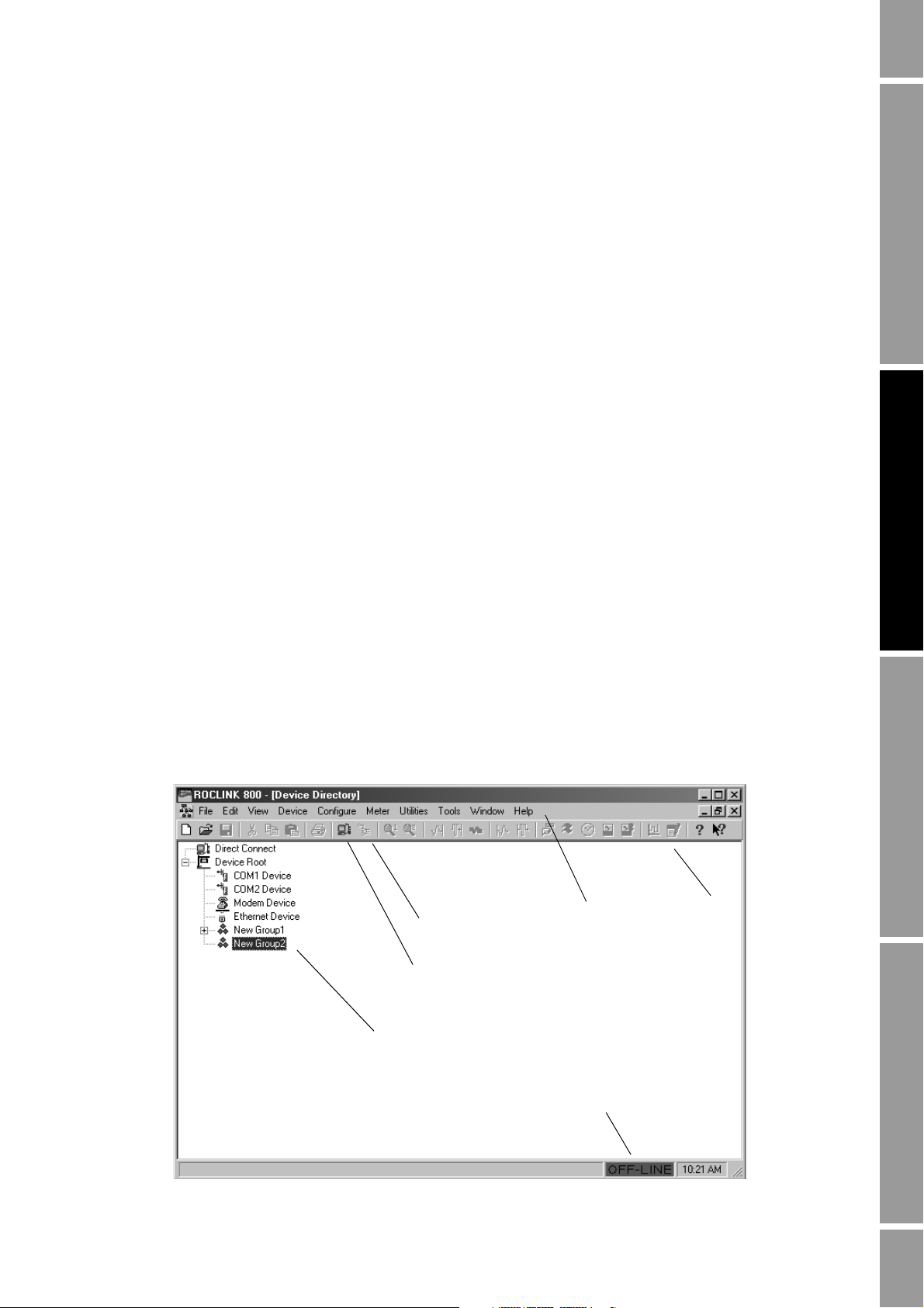
Upon successful login, the Device Directory window, shown in Figure 2-2, is displayed.
Figure 2-2 Device Directory window
Menu bar
Connect icon
Direct Connect icon
Toolbar
Device directory
Connection indicator
Configuration and Use Manual 7

Getting Started
ROCLINK 800 uses a standard Windows interface. Use standard Windows techniques to open and
close windows and dialog boxes, expand and hide options, etc.
ROCLINK 800 windows
ROCLINK 800 windows can be maximized, minimized, or resized, using the standard Windows
controls.
In addition, the Windows menu lists all windows that are currently open, and allows you to arrange
them on the screen or bring a specific window to the top. Figure 2-3 shows ROCLINK 800 with three
windows open and cascaded.
Figure 2-3 Cascaded windows
8 Micro Motion® Model 3711 Gas Flow Computers

Getting Started
ROCLINK 800 buttons
Several buttons are used to manage the ROCLINK 800 interface or data exchange with the
Model 3711 component. They do not interact with the core processor component. These buttons are
found on many ROCLINK 800 windows and dialog boxes (see Figure 2-4):
•
OK – Closes the current window or dialog box. If there are any unsaved changes on the screen,
a popup is displayed, asking the user if the changes should be saved to the Model 3711
configuration.
Apply – Writes the configuration parameters that are currently shown on the ROCLINK 800
•
display to the Model 3711 configuration.
•
Cancel – Closes the current window or dialog box without changing any parameters, and
without displaying a confirmation popup.
•
Update – Updates the display from current values in the Model 3711.
•
Auto Scan and Stop Scan – Enables and disables the Auto Scan feature. Auto Scan
automatically updates the display from the Model 3711, at configured intervals. See
Section 3.5 for information on configuring the Auto Scan interval.
Getting Started CommunicationsSystemBefore You Begin
If Auto Scan is not enabled, it may be useful to click
Apply, then click Update, so that the screen
displays the results of your actions.
Figure 2-4 Common buttons
Two additional buttons – the
Write Config and Read Config buttons – manage data exchange with
the core processor component as well as the Model 3711 component:
•The
Write Config Data button writes the displayed configuration parameters to the core
processor. If you have changed a parameter in ROCLINK 800, but not written it to the
Model 3711, a popup is displayed to allow you to save the change to the Model 3711.
- If you click
Yes, the change is saved to the Model 3711, and then written to the core
processor.
- If you click
No, the change is discarded and nothing is written to the Model 3711 or the
core processor.
•The
Read Config Data button reads configuration parameters from the core processor and
updates the ROCLINK 800 display. If you have changed a parameter in ROCLINK 800 but
not written it to the Model 3711, a popup is displayed to allow you to save the change.
- If you click
Yes, the change is written to the Model 3711 and the core processor before
values are read back to the display.
- If you click
No, the change is discarded and the existing values in the core processor are
read back to the display.
These buttons appear only on the Mass Flow, Density, and Temperature panels (see Section 5.4).
Note: The core processor is the component which provides preprocessing of the sensor data. In the
Model 3711 system, ROCLINK 800 communicates with the Model 3711 component, which in turn
communicates with the core processor component, which communicates with the sensor.
Configuration and Use Manual 9
Getting Started
2.4.3 TLP system
Particular locations, or “points,” in Model 3711 memory are identified using a TLP system, where:
For example, a TLP value of
output associated with point B3 in the Model 3711’s physical memory.
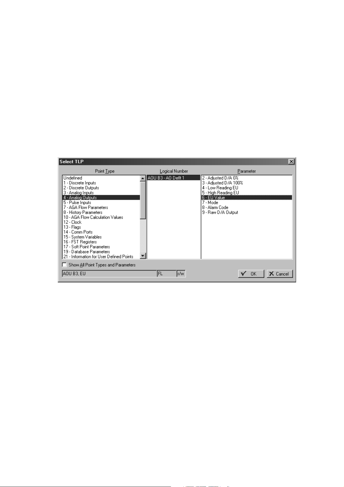
ROCLINK 800 uses the TLP system during configuration. When the TLP symbol (an ellipsis, or
displayed on a button, the button provides access to the Select TLP dialog box, shown in Figure 2-5.
Figure 2-5 Select TLP dialog box
•T = Type
• L = Logical number
•P = Parameter
AOU B3, EU represents the value, in engineering units, of the analog
...) is
TLP notation can be text, as shown here, or numeric. For example, if numeric notation is configured,
AOU B3, EU will be represented as 4 18, 6. See Section 3.5 for information on configuring TLP
notation.
To use the Select TLP dialog box:
1. Highlight the point type of the desired point.
2. Highlight the logical number of the desired point.
3. Highlight the desired parameter associated with the specified point.
See Appendix C for additional information on points and the TLP system.
10 Micro Motion® Model 3711 Gas Flow Computers

Getting Started
2.5 Configuration files
When using ROCLINK 800 to configure the Model 3711, two types of configuration files are
involved:
• The ROCLINK 800 configuration file is specific to each installation of ROCLINK 800 on a
PC. It is created automatically, and automatically saved to a file each time that ROCLINK 800
is closed. It contains device and group definitions (see Section 2.6), and other items that are
specific to the ROCLINK 800 software, rather than to a device. No user actions are required to
create and maintain the ROCLINK 800 configuration file.
• A device configuration file is a set of operating parameters that are defined in ROCLINK 800,
then applied or downloaded to the Model 3711. Multiple device configuration files may be
defined in ROCLINK 800, and stored as files on the PC; however, only one device
configuration file can be loaded into the Model 3711 at any one time. A device configuration
file must be specifically created and saved by the user.
2.5.1 Managing device configuration files
The ROCLINK 800 File menu is used to open and close device configuration files within
ROCLINK 800, and to save a device configuration file to the PC. The File menu is also used to print a
device configuration file (see Section 14.11) and to download a device configuration file into the
Model 3711 (see Section 14.10.3).
All device configuration files use the .800 extension. You can create as many device configuration
files as you need. Each device configuration file contains information describing one Model 3711,
including its interaction with the sensor, its I/O configuration, its history setup, and so on.
Note: If you use this installation of ROCLINK 800 to interact with other devices, including
non–Model 3711 devices, their device configuration files will also use the .800 extension. Be sure to
name the device configuration files so that you will be able to identify the device and device type.
Only one device configuration file can be loaded to a Model 3711. However, multiple device
configuration files can be open within ROCLINK 800 at one time. Each device configuration file
displayed in a separate Configuration Tree window. The Window menu can be used to select the
device configuration file that you want to view or use.
Saving a device configuration file to the PC is not the same as saving it to flash memory in the
Model 3711. To save a device configuration to flash memory, click
Save Configuration
. The configuration data in flash memory is used in all cold restarts, and may be
Device > Flags >
used in warm restarts. For more information on flash memory and restart options, see Section 14.2.
Getting Started CommunicationsSystemBefore You Begin
2.5.2 Creating a new device configuration file
You do not have to be connected to a Model 3711 to create a device configuration file. However, you
will need to be connected to a Model 3711 to configure many of the properties that are saved in a
device configuration file.
To create a new device configuration file:
1. Click
2. In the upper left corner of the New Configuration File window, set
Configuration and Use Manual 11
File > New.
Configuration Type to
FB104/3711. The shown in Figure 2-6 is displayed.

Getting Started
Figure 2-6 New Configuration File dialog box
3. Specify your I/O type.
• If your Model 3711 was ordered without the optional 6-point I/O expansion termination
board, select
6-point no I/O.
• If your Model 3711 was ordered with the optional 6-point I/O expansion termination
board, select
4. If you specified
6-point with I/O.
6-point with I/O, an External I/O frame is displayed. Use the options in this
frame to specify how five of the six I/O channels will be used (the sixth channel is always used
as a discrete output). The I/O types specified here must be compatible with the I/O wiring and
switches (see the Model 3711 installation manual for wiring instructions). You can change
these specifications later (see Section 7.3).
5. Specify the number of PID control loops that will be configured for this Model 3711. The
maximum value is 1. This value can be changed later. See Chapter 10 for more information.
6. Specify the maximum number of history points to be used for standard history and extended
history. If you add history points later, you will lose all existing history, so make sure that the
number specified will be sufficient for your Model 3711. See Chapter 8 for more information
about history.
7. Click
8. Specify a name and location to be used for the configuration file, and click
Start.
Save. All
ROCLINK 800 configuration files use the .800 extension.
9. If you want to continue with configuration, open the file when prompted. If you will perform
configuration later, close the file.
12 Micro Motion® Model 3711 Gas Flow Computers

Getting Started
2.5.3 Device configuration backup and duplication
Once a device configuration file has been saved to your PC, it can be downloaded to any Model 3711.
This feature allows you to replicate a configuration across multiple Model 3711 installations. When
downloading, you can select specific types of configuration data as required (see Section 14.10.3).
2.6 Setting up devices and groups
Each Model 3711 is a ROCLINK 800 device. All ROCLINK 800 devices can be organized into
groups. Typically, a group contains all Model 3711 devices within one geographical area.
You do not need to be connected to a Model 3711 to add devices or groups. Device and group
definitions are stored within ROCLINK 800.
The Device Directory window (see Figure 2-2) shows the predefined entities. To open the Device
Directory window, click
Window > Device Directory or View > Directory.
Add the appropriate groups and devices for all Model 3711 devices that you will connect to from this
ROCLINK 800 installation.
Getting Started CommunicationsSystemBefore You Begin
• Right-click on
Device Root to:
- Add a device in Device Root
- Add a group in Device Root
- Delete all devices in Device Root
• Right-click on a group name to:
- Add a device to the current group
- Add a group within the current group
- Delete the current group (including all lower-level groups and devices)
- Delete all devices in the current group
- Rename the current group
• Right-click on a device name to:
- Set properties for the current device
- Rename the current device
- Delete the current device
2.7 First connection to the Model 3711
The first connection to the Model 3711 must be made through the Local Operator Interface (LOI)
port, so that default settings can be used. The LOI port always responds to connection requests made
to Device Address
240, Device Group 240. The Direct Connect function uses these default settings.
This connection can be used to configure address information, baud rate, etc., for use with subsequent
connections. For information on configuring communications, see Chapter 4.
To make the first connection to the Model 3711:
1. Ensure that the LOI cable from the Model 3711 is correctly wired to your PC (see the
Model 3711 installation manual).
Configuration and Use Manual 13

Getting Started
CAUTION
Removing the termination board cover in hazardous environments could
result in personal injury or property damage.
Any procedure that requires removal of the enclosure end caps must be performed
only in an area known to be non-hazardous. Performance of these procedures in a
hazardous area could result in personal injury or property damage.
2. Ensure that the COM port on the PC is configured for 8 data bits.
3. Ensure that the Model 3711 is powered up.
4. Click the
Direct Connect
Direct Connect icon in the toolbar (see Figure 2-2), or click Device >
.
ROCLINK 800 makes connection attempts, beginning with COM port 1 on the PC at baud rates
between 1200 and 19.2K. It works through all COM ports on the PC, at all baud rates, until the
connection attempt succeeds.
When a successful connection is made, ROCLINK 800 displays the Configuration Tree window (see
Figure 2-7). This window displays data from the currently connected Model 3711.
Figure 2-7 Configuration Tree window
Close ROCLINK 800
Disconnect from device
2.7.1 Disconnecting and closing
To disconnect from the Model 3711, close the Configuration Tree window by clicking on the
upper right corner of the window (see Figure 2-7), or by clicking
To close ROCLINK 800, either click on the
File > Exit.
14 Micro Motion® Model 3711 Gas Flow Computers
X in the upper right corner of the main window, or click
File > Close.
X in the

Chapter 3
System Configuration
3.1 Overview
This chapter discusses the following topics:
• Setting the Model 3711 clock
• Configuring security
• Configuring device information
• Configuring the Auto Scan interval
• Configuring TLP display options
Note: During the configuration process, save your data frequently, both to the PC and to the
Model 3711’s flash memory. To save your data to a file, click File > Save Configuration. To save your
data to flash memory, click Device > Flags > Save Configuration. For information on flash memory,
see Section 14.3.
Getting Started CommunicationsSystemBefore You Begin
3.2 Setting the Model 3711 clock
Setting the Model 3711 clock is required for accurate timestamping and control of the historical
databases, event log, and alarm log.
To set the Model 3711 clock:
1. Connect to the Model 3711.
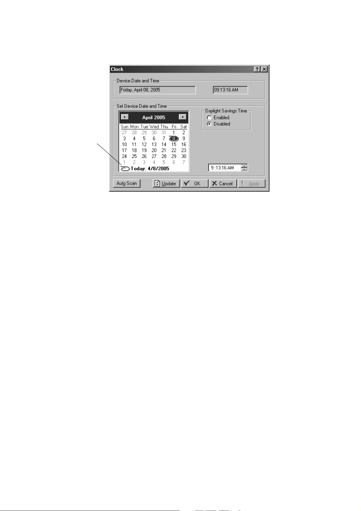
2. Click
3. If the clock in your PC is set correctly, click the red circle in the lower left corner of the
4. If you want the clock in the Model 3711 to automatically adjust for daylight savings time,
5. Click
6. Click
7. Click
Device > Clock, or click the Clock icon in the toolbar. The dialog box shown in
Figure 3-1 is displayed.
calendar to synchronize the Model 3711 clock to the PC clock. If the clock in your PC is not
set correctly, use the ROCLINK 800 calendar to select the day, month, and year. Then enter the
time in the time field, or use the arrows. Use
click
Enabled.
Apply.
Update to update the ROCLINK 800 screen to the current Model 3711 value.
OK.
A and P for AM and PM.
Configuration and Use Manual 15
System Configuration
Figure 3-1 Clock dialog box
Red circle
3.3 Configuring security
Using ROCLINK 800 with the Model 3711 requires two types of security:
• Access to the ROCLINK 800 software (ROCLINK 800 security)
• Access to the COM ports on the Model 3711 (device security)
The ROCLINK 800 operator ID and password are required when you start the ROCLINK 800
program. The Model 3711 device operator ID and password are required when you connect to the
Model 3711 if device security is enabled on the com port that you are using.
3.3.1 ROCLINK 800 security
Up to 21 ROCLINK 800 operator IDs may be defined. To define a ROCLINK 800 operator ID:
1. Click
Utilities > ROCLINK 800 Security. The dialog box shown in Figure 3-2 is displayed,
showing the default operator ID and password. This operator ID is used for initial setup of the
Model 3711.
Note: Access level 5 is required to open the ROCLINK 800 Security dialog box. If you want to change
security settings after initial setup is complete, you must use an operator ID with this access level.
16 Micro Motion® Model 3711 Gas Flow Computers

System Configuration
Figure 3-2 ROCLINK 800 Security dialog box
Getting Started CommunicationsSystemBefore You Begin
2. To add an operator ID:
a. Enter a 1–3 character value in the
Operator ID column. Any alphanumeric character may
be used. All operator IDs must be unique on this ROCLINK 800 installation. The field is
case-sensitive.
b. Enter a 1–4 character value in the
Password column. Only numeric characters may be
used. Passwords do not have to be unique.
c. Enter the access level to be assigned to this operator ID. See Section 3.3.3.
3. When all desired operator IDs have been defined, click
Save.
Note: You cannot save an operator ID without a password, or a password without an operator ID.
You can save an operator ID and password without an access level.
4. To delete an operator ID, password, or access level, highlight the cell and press
Delete, or
backspace over the value.
Note: For security reasons, Micro Motion recommends that the default operator ID be deleted after
appropriate administrative operator IDs have been defined.
3.3.2 Device security
You can enable or disable device security for the LOI and for COM1 and COM2. For each comm
port, you can enable security by operator ID or by access level.
The operator ID and password used to login to ROCLINK 800 will automatically be used for the
Model 3711 login attempt. Therefore, for each ROCLINK 800 operator ID which will be used to
access the Model 3711, define a matching Model 3711 operator ID. Up to 16 Model 3711 operator
IDs may be defined.
Configuration and Use Manual 17
System Configuration
To manage device security:
1. Connect to the Model 3711.
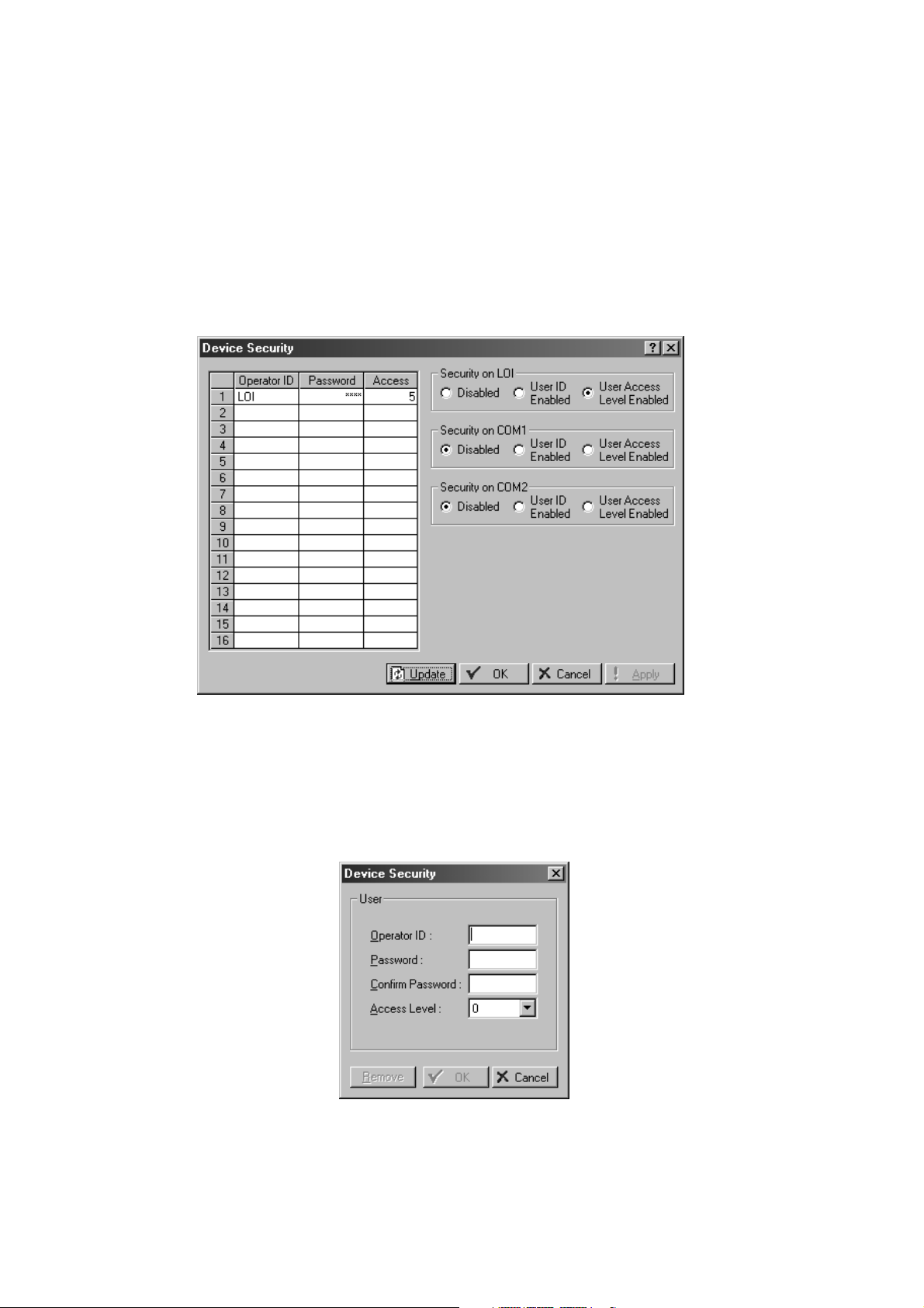
2. Click
showing the default operator ID. Passwords are concealed. The default password is
Note: Access level 5 is required to open the Device Security dialog box. If you want to change security
settings after initial setup is complete, you must use an operator ID with this access level.
Figure 3-3 Device Security dialog box
Device > Security. The Device Security dialog box shown in Figure 3-3 is displayed,
1000.
3. To add an operator ID:
a. Click on any empty cell in the table. The Device Security popup will be displayed (see
Figure 3-4).
Figure 3-4 Device Security popup
18 Micro Motion® Model 3711 Gas Flow Computers

System Configuration
b. Enter values as required.
c. Click
4. To edit an entry, click on any cell in that entry. Using the Device Security popup, edit the
values and click
5. To remove an entry, click on any cell in that entry. Using the Device Security popup, click
Remove.
6. To enable or disable security for LOI, COM 1, and COM 2, click the radio button for the type
of security to be enforced:
•
•
• The operator ID must be a 1–3 character value. Any alphanumeric character may be
used. The operator ID should be unique; however, no check is performed. The field is
case-sensitive.
• The password must be a 1–4 character value. Only numeric characters may be used.
The password does not have to be unique.
• See Section 3.3.3 for information about access level.
OK.
OK.
Getting Started CommunicationsSystemBefore You Begin
Disabled – All login requests are accepted.
User ID Enabled – Login requests are accepted if the operator ID and password are valid
on the Model 3711. Upon successful login, full access is allowed to all ROCLINK 800
screens and functions.
•
User Access Level Enabled – Login requests are accepted only if both of the following
are true:
- The operator ID and password are valid.
- The access level of the Model 3711 operator ID is equal to or higher than the access
level of the ROCLINK 800 operator ID.
Upon successful login, the access level of the ROCLINK 800 operator ID and the
Model 3711 operator ID are compared, and the user is limited to the lower access level.
Note: If security is enabled on any port, at least one user must be defined with access level 5.
3.3.3 Access level
For each operator ID, an access level is specified. The access levels control access to specific
ROCLINK 800 screens. Both ROCLINK 800 security and Model 3711 security use access levels.
Any access level implicitly includes all lower access levels; i.e., if access level 3 has been assigned to
an operator ID, that operator ID can also perform all actions that require access level 1 or 2.
Table 3-1 lists the ROCLINK 800 screens and the required access levels.
Configuration and Use Manual 19

System Configuration
Tabl e 3-1 Access levels for ROCLINK 800 security and device security
Menu Option Access level required
File New 3
Edit All 0
View Directory 0
Device Direct Connect 0
Configure All 3
Meter All 2
Open 1
Download 3
Close 2
Save Configuration 3
Print Configuration 1
Print Setup 0
Recent Files 0
Exit 1
EFM Report 3
Calibration Report 2
History > From ROC 2
History > From File 1
History > Between Dates 1
Alarms > From ROC 2
Alarms > From File 1
Events > From ROC 2
Events > From File 1
Audit Log > From ROC 1
Audit Log > From File 1
Display > New 3
Display > Display 1 0
Display > Display 2 0
Display > From File 0
I/O Monitor 2
Toolbar 0
Connect 0
Collect Data 2
Clock 3
Security 5
Comm Ports 3
Memory 1
ROC Information 3
ROC Flags 3
20 Micro Motion® Model 3711 Gas Flow Computers

System Configuration
Tabl e 3-1 Access levels for ROCLINK 800 security and device security continued
Menu Option Access level required
Utilities Upgrade Firmware 4
Tools Customize 0
Window All 0
Help All 0
Upgrade Hardware 4
Upgrade to FlashPAC 4
License Key Administrator 5
Convert EFM File 3
User Program Administrator 4
ROCLINK Security 5
AI Calibration Values 3
RTD Calibration Values 3
MVS Calibration Values 3
FST Editor 3
Debug Communications 0
Options 3
Getting Started CommunicationsSystemBefore You Begin
3.4 Configuring Model 3711 device information
Model 3711 device information includes Model 3711 address information and several other types of
information.
To configure device information parameters:
1. Click
Device > Information. The Device Information dialog box shown in Figure 3-5 is
displayed.
Configuration and Use Manual 21
System Configuration
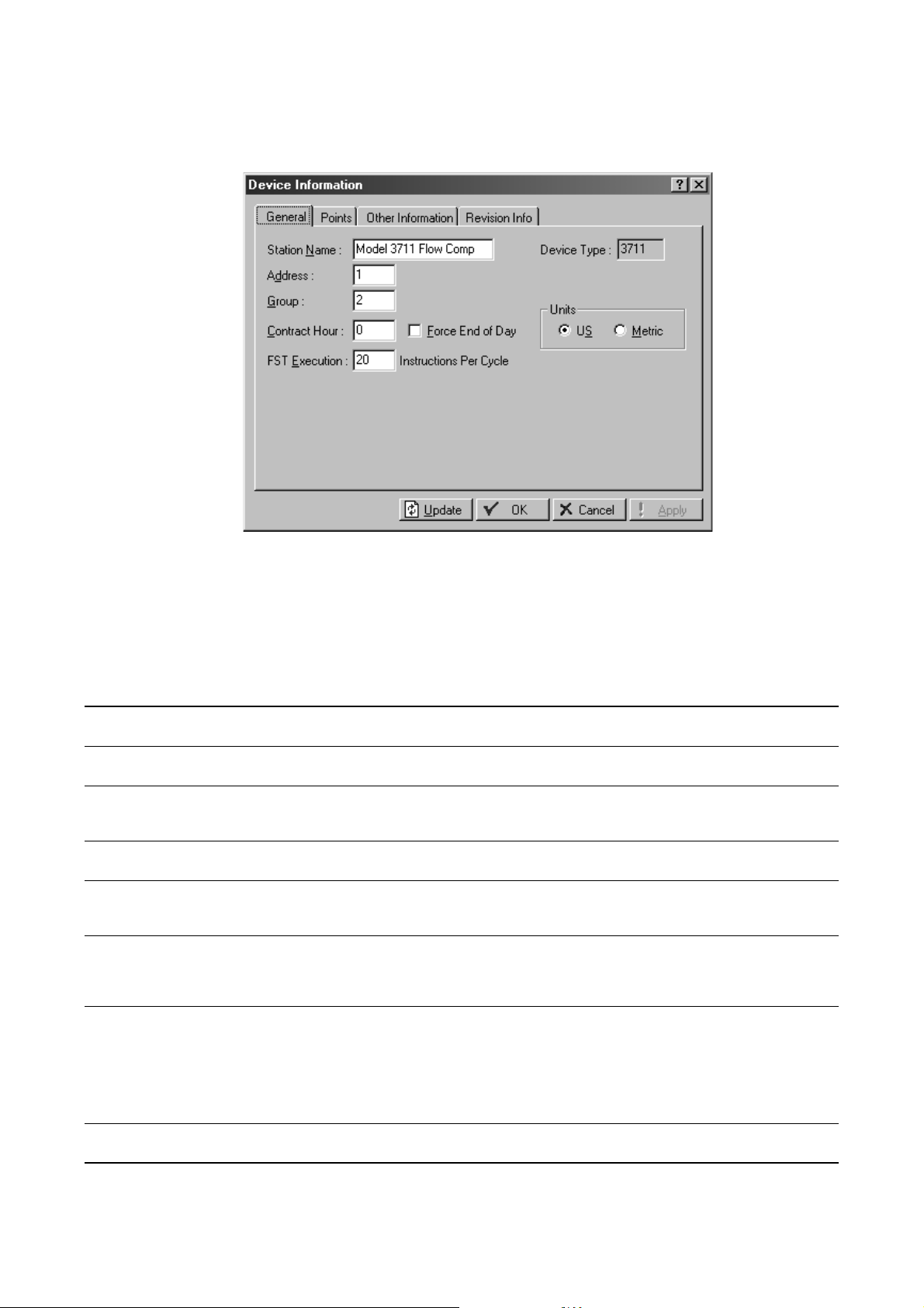
Figure 3-5 Device Information dialog box
2. On the General tab, configure parameters as required. Parameters are listed and defined in
Tabl e 3 -2 .
Tabl e 3-2 Device Information dialog box – General panel
Parameter Description Comments
Station Name Name of this Model 3711 Corresponds to Tag value in Communication
Properties dialog box
Address Address to be assigned to this Model 3711.
This value must be unique within the group.
Group Group to which this Model 3711 belongs. A
group typically describes a set of devices in
the same geographical area.
Device Type Read-only. Displays the device type of the
Model 3711.
Contract Hour Time at which values are totaled for a
single day of production and data is logged
to Daily History database
Force End of Day Current day and hourly values will be
logged into memory for all historical data
except station totals. Resets daily and
hourly accumulators.
FST Execution Controls the number of FST instructions to
be executed during one FST execution
period (one second). See Section 11.2.
Units Controls the type of unit used for display
and for calculations.
Corresponds to Device address value in
Communication Parameters dialog box
Corresponds to Device group value in Communication
Parameters dialog box, and to Group number in Device
Directory window
Uses one of the 35 available slots in the standard
history database.
Default: 20. Range: 1–100.
Changes to this parameter take effect in the next FST
execution period. Restart is not required.
To reduce the risk of overloading the Model 3711,
monitor the MPU (Micro Processor Unit) loading when
changes to this parameter are made. See
Section 15.7.
Enter all values in units appropriate to the system of
units specified here.
22 Micro Motion® Model 3711 Gas Flow Computers
 Loading...