


Configuration and Use Manual
MMI-20020959, Rev AC
Micro Motion® Fork Density Meters (FDM)
Configuration and Use Manual
April 2016

Safety messages
Safety messages are provided throughout this manual to protect personnel and equipment. Read each safety message carefully
before proceeding to the next step.
Emerson Flow customer service
Email:
• Worldwide: flow.support@emerson.com
• Asia-Pacific: APflow.support@emerson.com
Telephone:
North and South America Europe and Middle East Asia Pacific
United States 800-522-6277 U.K. 0870 240 1978 Australia 800 158 727
Canada +1 303-527-5200 The Netherlands +31 (0) 704 136 666 New Zealand 099 128 804
Mexico +41 (0) 41 7686 111 France 0800 917 901 India 800 440 1468
Argentina +54 11 4837 7000 Germany 0800 182 5347 Pakistan 888 550 2682
Brazil +55 15 3413 8000 Italy 8008 77334 China +86 21 2892 9000
Venezuela +58 26 1731 3446 Central & Eastern +41 (0) 41 7686 111 Japan +81 3 5769 6803
Russia/CIS +7 495 981 9811 South Korea +82 2 3438 4600
Egypt 0800 000 0015 Singapore +65 6 777 8211
Oman 800 70101 Thailand 001 800 441 6426
Qatar 431 0044 Malaysia 800 814 008
Kuwait 663 299 01
South Africa 800 991 390
Saudi Arabia 800 844 9564
UAE 800 0444 0684

Contents
Contents
Part I Getting Started
Chapter 1 Before you begin ............................................................................................................3
1.1 About this manual ....................................................................................................................... 3
1.2 Model codes and device types ..................................................................................................... 3
1.3 Communications tools and protocols .......................................................................................... 4
1.4 Additional documentation and resources .................................................................................... 5
Chapter 2 Quick start .....................................................................................................................7
2.1 Power up the transmitter .............................................................................................................7
2.2 Check meter status ......................................................................................................................7
2.3 Make a startup connection to the transmitter ..............................................................................8
Part II Configuration and commissioning
Chapter 3 Introduction to configuration and commissioning ....................................................... 13
3.1 Default values ............................................................................................................................13
3.1.1 FDM default values ..................................................................................................... 13
3.2 Enable access to the off-line menu of the display ....................................................................... 14
3.3 Disable HART security ................................................................................................................15
3.4 Set the HART lock ...................................................................................................................... 17
3.5 Restore the factory configuration .............................................................................................. 17
Chapter 4 Configure process measurement ..................................................................................19
4.1 Verify the calibration factors ......................................................................................................19
4.1.1 Calibration factors ...................................................................................................... 20
4.2 Configure line density measurement ........................................................................................ 20
4.2.1 Configure Density Measurement Unit ................................................................................20
4.2.2 Configure Density Damping ........................................................................................... 22
4.2.3 Configure Density Cutoff ................................................................................................ 23
4.2.4 Configure two-phase flow parameters ........................................................................24
4.3 Configure temperature measurement .......................................................................................25
4.3.1 Configure Temperature Measurement Unit ........................................................................ 25
4.3.2 Configure Temperature Damping .....................................................................................26
4.3.3 Configure Temperature Input .......................................................................................... 27
4.4 Configure the pressure input ..................................................................................................... 30
4.4.1 Configure the pressure input using ProLink III ............................................................. 30
4.4.2 Configure the pressure input using the Field Communicator .......................................32
4.4.3 Options for Pressure Measurement Unit ........................................................................... 33
4.5 Set up the API referral application ..............................................................................................34
4.5.1 Set up the API referral application using ProLink III ...................................................... 34
4.5.2 Set up the API referral application using the Field Communicator ............................... 40
4.6 Set up concentration measurement .......................................................................................... 47
4.6.1 Preparing to set up concentration measurement ........................................................47
4.6.2 Set up concentration measurement using ProLink III ...................................................48
Configuration and Use Manual i

Contents
4.6.3 Set up concentration measurement using the Field Communicator ............................55
4.6.4 Using equations to calculate specific gravity, °Baumé, °Brix, °Plato, and °Twaddell ......60
4.6.5 Matrix switching ......................................................................................................... 61
4.6.6 Measuring Net Mass Flow Rate and Net Volume Flow Rate ..........................................63
4.7 Set up flow rate measurement ...................................................................................................63
4.7.1 Set up flow rate measurement using ProLink III ...........................................................63
4.7.2 Set up flow rate measurement using the Field Communicator .................................... 65
Chapter 5 Configure device options and preferences ....................................................................67
5.1 Configure the transmitter display .............................................................................................. 67
5.1.1 Configure the language used for the display ............................................................... 67
5.1.2 Configure the process variables and diagnostic variables shown on the display ...........68
5.1.3 Configure the number of decimal places (precision) shown on the display ..................68
5.1.4 Configure the refresh rate of data shown on the display ..............................................69
5.1.5 Enable or disable automatic scrolling through the display variables ............................ 69
5.2 Enable or disable the Acknowledge All Alerts display command ......................................................70
5.3 Configure security for the display menus .................................................................................. 71
5.4 Configure alert handling ............................................................................................................72
5.4.1 Configure Fault Timeout .................................................................................................72
5.4.2 Configure Alert Severity ................................................................................................. 73
5.5 Configure informational parameters ......................................................................................... 75
Chapter 6 Integrate the meter with the control system ................................................................77
6.1 Configure Channel B ..................................................................................................................77
6.2 Configure the mA output .......................................................................................................... 78
6.2.1 Configure mA Output Process Variable ............................................................................. 78
6.2.2 Configure Lower Range Value (LRV) and Upper Range Value (URV) ....................................80
6.2.3 Configure Added Damping ............................................................................................. 81
6.2.4 Configure mA Output Fault Action and mA Output Fault Level ...............................................82
6.3 Configure the discrete output ................................................................................................... 84
6.3.1 Configure Discrete Output Source ....................................................................................84
6.3.2 Configure Discrete Output Polarity ................................................................................... 85
6.3.3 Configure Discrete Output Fault Action ............................................................................. 86
6.4 Configure an enhanced event ....................................................................................................87
6.5 Configure HART/Bell 202 communications ............................................................................... 88
6.5.1 Configure basic HART parameters ...............................................................................88
6.5.2 Configure HART variables (PV, SV, TV, QV) ..................................................................89
6.5.3 Configure burst communications ............................................................................... 91
6.6 Configure Modbus communications ..........................................................................................95
6.7 Configure Digital Communications Fault Action ................................................................................. 97
6.7.1 Options for Digital Communications Fault Action .................................................................97
Chapter 7 Complete the configuration ......................................................................................... 99
7.1 Test or tune the system using sensor simulation ........................................................................99
7.2 Back up transmitter configuration ............................................................................................. 99
7.3 Enable HART security ...............................................................................................................100
Part III Operations, maintenance, and troubleshooting
Chapter 8 Transmitter operation ................................................................................................105
8.1 Record the process variables ................................................................................................... 105
8.2 View process variables and diagnostic variables ...................................................................... 105
ii Micro Motion® Fork Density Meters (FDM)

Contents
8.2.1 View process variables using the display ................................................................... 105
8.2.2 View process variables and other data using ProLink III ............................................. 106
8.2.3 View process variables using the Field Communicator .............................................. 106
8.3 View and acknowledge status alerts ........................................................................................ 107
8.3.1 View and acknowledge alerts using the display ........................................................ 107
8.3.2 View and acknowledge alerts using ProLink III ...........................................................109
8.3.3 View alerts using the Field Communicator ................................................................ 110
8.3.4 Alert data in transmitter memory ............................................................................. 110
Chapter 9 Measurement support ............................................................................................... 113
9.1 Perform the inline calibration check procedure ....................................................................... 113
9.1.1 Perform the inline calibration check using ProLink III .................................................114
9.1.2 Perform the inline calibration check using the Field Communicator ..........................115
9.2 Perform the Known Density Verification procedure .................................................................115
9.2.1 Perform the Known Density Verification procedure using the display ....................... 116
9.2.2 Perform the Known Density Verification procedure using ProLink III ......................... 117
9.2.3 Perform the Known Density Verification procedure using the
Field Communicator ................................................................................................. 117
9.3 Adjust density measurement with Density Offset or Density Meter Factor ....................................... 118
9.4 Perform density offset calibration ............................................................................................119
9.4.1 Perform density offset calibration using the display .................................................. 120
9.4.2 Perform density offset calibration using ProLink III ....................................................121
9.4.3 Perform density offset calibration using the Field Communicator ............................. 121
9.5 Perform temperature calibration .............................................................................................122
9.5.1 Perform temperature calibration using the display ................................................... 122
9.5.2 Perform temperature calibration using ProLink III .................................................... 123
9.5.3 Perform temperature calibration using the Field Communicator ..............................123
9.6 Adjust concentration measurement with Trim Offset .................................................................124
9.7 Adjust concentration measurement with Trim Slope and Trim Offset ........................................... 125
9.8 Set up user-defined calculations .............................................................................................. 127
9.8.1 Equations used in user-defined calculations ..............................................................129
9.8.2 Measurement units used in user-defined calculations ............................................... 129
Chapter 10 Troubleshooting ........................................................................................................ 131
10.1 Quick guide to troubleshooting ...............................................................................................131
10.2 Check power supply wiring ......................................................................................................132
10.3 Check grounding .....................................................................................................................133
10.4 Perform loop tests ...................................................................................................................133
10.4.1 Perform loop tests using the display ......................................................................... 134
10.4.2 Perform loop tests using ProLink III ........................................................................... 135
10.4.3 Perform loop tests using the Field Communicator .................................................... 136
10.5 Status LED states ..................................................................................................................... 137
10.6 Status alerts, causes, and recommendations ........................................................................... 138
10.7 Density measurement problems ............................................................................................. 143
10.8 Temperature measurement problems .....................................................................................144
10.9 API referral problems ...............................................................................................................145
10.10 Concentration measurement problems ...................................................................................145
10.11 Milliamp output problems ....................................................................................................... 146
10.12 Discrete output problems ........................................................................................................148
10.13 Time Period Signal (TPS) output problems ...............................................................................148
10.14 Using sensor simulation for troubleshooting ........................................................................... 149
10.15 Trim mA outputs ..................................................................................................................... 149
Configuration and Use Manual iii

Contents
10.15.1 Trim mA outputs using ProLink III ..............................................................................149
10.15.2 Trim mA outputs using the Field Communicator .......................................................150
10.16 Check HART communications ................................................................................................. 151
10.17 Check Lower Range Value and Upper Range Value ......................................................................... 152
10.18 Check mA Output Fault Action ...................................................................................................... 153
10.19 Check for radio frequency interference (RFI) ............................................................................153
10.20 Check the cutoffs .................................................................................................................... 153
10.21 Check for two-phase flow (slug flow) .......................................................................................154
10.22 Check the drive gain ................................................................................................................ 154
10.22.1 Collect drive gain data .............................................................................................. 155
10.23 Check for internal electrical problems ..................................................................................... 155
10.24 Locate a device using the HART 7 Squawk feature ................................................................... 156
Appendices and reference
Appendix A Calibration certificate ................................................................................................ 157
A.1 Sample calibration certificate ................................................................................................. 157
Appendix B Using the transmitter display ..................................................................................... 159
B.1 Components of the transmitter interface ................................................................................ 159
B.2 Use the optical switches .......................................................................................................... 159
B.3 Access and use the display menu system .................................................................................160
B.3.1 Enter a floating-point value using the display ............................................................161
B.4 Display codes for process variables ..........................................................................................164
B.5 Codes and abbreviations used in display menus ...................................................................... 164
Appendix C Using ProLink III with the transmitter .........................................................................177
C.1 Basic information about ProLink III ...........................................................................................177
C.2 Connect with ProLink III ........................................................................................................... 178
C.2.1 Connection types supported by ProLink III ................................................................ 178
C.2.2 Connect with ProLink III over Modbus/RS-485 ...........................................................179
C.2.3 Connect with ProLink III over HART/Bell 202 ............................................................. 182
Appendix D Using the Field Communicator with the transmitter ................................................... 191
D.1 Basic information about the Field Communicator ....................................................................191
D.2 Connect with the Field Communicator .................................................................................... 192
Appendix E Concentration measurement matrices, derived variables, and process variables ........ 195
E.1 Standard matrices for the concentration measurement application ........................................ 195
E.2 Concentration measurement matrices available by order ........................................................196
E.3 Derived variables and calculated process variables .................................................................. 198
iv Micro Motion® Fork Density Meters (FDM)

Part I
Getting Started
Chapters covered in this part:
• Before you begin
• Quick start
Getting Started
Configuration and Use Manual 1

Getting Started
2 Micro Motion® Fork Density Meters (FDM)

1 Before you begin
Topics covered in this chapter:
• About this manual
• Model codes and device types
• Communications tools and protocols
• Additional documentation and resources
1.1 About this manual
This manual provides information to help you configure, commission, use, maintain, and
troubleshoot the Micro Motion Fork Density Meter (FDM).
The following versions of the FDM are documented in this manual:
• Fork Density Meter with Analog Outputs
• Fork Density Meter with Analog Output and Discrete Output
• Fork Density Meter with Time Period Signal Output
Before you begin
For the Fork Density Meter with FOUNDATION™ Fieldbus, see Micro Motion® Fork Density
Meters with FOUNDATION™ Fieldbus: Configuration and Use Manual.
Important
This manual assumes that the following conditions apply:
• The meter has been installed correctly and completely, according to the instructions in the
installation manual.
• The installation complies with all applicable safety requirements.
• The user is trained in all government and corporate safety standards.
1.2 Model codes and device types
Your device can be identified by the model code on the device tag.
Model codes and device typesTable 1-1:
Model code Device nickname I/O
FDM*****C FDM mA • Two mA outputs
• RS-485 terminals
FDM*****D FDM DO • One mA output
• One discrete output
• RS-485 terminals
Electronics mounting
Integral
Integral
Configuration and Use Manual 3

Before you begin
Model codes and device types (continued)Table 1-1:
Model code Device nickname I/O
FDM*****B FDM TPS • One mA output
• One Time Period Sig-
nal output
FDM*****A FDM FF • FOUNDATION™ field-
bus
Restriction
The FDM and FDM FF support a complete set of application and configuration options. The FDM DO
and FDM TPS support a subset of configuration options. Refer to the product data sheet for details.
1.3 Communications tools and protocols
You can use several different communications tools and protocols to interface with the
device. You may use different tools in different locations or for different tasks.
Electronics mounting
Integral
4-wire remote
transmitter
Communications tools, protocols, and related informationTable 1-2:
Communications tool Supported protocols Scope In this manual For more information
Display Not applicable Basic configuration and
commissioning
ProLink III • Modbus/RS-485
• HART/Bell 202
• Service port
Field Communicator
• HART/Bell 202 Complete configuration
Tip
You may be able to use other communications tools from Emerson Process Management, such as
AMS Suite: Intelligent Device Manager, or the Smart Wireless THUM™ Adapter. Use of AMS or the
Smart Wireless THUM Adapter is not discussed in this manual. For more information on the Smart
Wireless THUM Adapter, refer to the documentation available at www.micromotion.com.
Complete configuration
and commissioning
and commissioning
Complete user information. See Appendix B.
Basic user information.
See Appendix C.
Basic user information.
See Appendix D.
Not applicable
User manual
• Installed with soft-
ware
• On Micro Motion
user documentation
CD
• On Micro Motion
web site
(www.micromo‐
tion.com)
User manual on
Micro Motion web site
(www.micromo‐
tion.com )
4 Micro Motion® Fork Density Meters (FDM)

1.4 Additional documentation and resources
Micro Motion provides additional documentation to support the installation and operation
of the device.
Additional documentation and resourcesTable 1-3:
Topic Document
Device installation Micro Motion Fork Density Meters (FDM): Installation Manual
Product data sheet Micro Motion Fork Density Meters: Product Data Sheet
All documentation resources are available on the Micro Motion web site at
www.micromotion.com or on the Micro Motion user documentation DVD.
Before you begin
Configuration and Use Manual 5

Before you begin
6 Micro Motion® Fork Density Meters (FDM)

2 Quick start
Topics covered in this chapter:
• Power up the transmitter
• Check meter status
• Make a startup connection to the transmitter
2.1 Power up the transmitter
The transmitter must be powered up for all configuration and commissioning tasks, or for
process measurement.
1. Ensure that all transmitter and sensor covers and seals are closed.
WARNING!
To prevent ignition of flammable or combustible atmospheres, ensure that all covers
and seals are tightly closed. For hazardous area installations, applying power while
housing covers are removed or loose can cause an explosion.
Quick start
2. Turn on the electrical power at the power supply.
The transmitter will automatically perform diagnostic routines. During this period,
Alert 009 is active. The diagnostic routines should complete in approximately
30 seconds.
Postrequisites
Although the sensor is ready to receive process fluid shortly after power-up, the electronics
can take up to 10 minutes to reach thermal equilibrium. Therefore, if this is the initial
startup, or if power has been off long enough to allow components to reach ambient
temperature, allow the electronics to warm up for approximately 10 minutes before
relying on process measurements. During this warm-up period, you may observe minor
measurement instability or inaccuracy.
2.2 Check meter status
Check the meter for any error conditions that require user action or that affect
measurement accuracy.
1. Wait approximately 10 seconds for the power-up sequence to complete.
Immediately after power-up, the transmitter runs through diagnostic routines and
checks for error conditions. During the power-up sequence, Alert A009 is active.
This alert should clear automatically when the power-up sequence is complete.
2. Check the status LED on the transmitter.
Configuration and Use Manual 7

Quick start
Transmitter status reported by status LEDTable 2-1:
LED state Description Recommendation
Green No alerts are active. Continue with configuration or process meas-
urement.
Yellow One or more low-severity alerts are active. A low-severity alert condition does not affect
measurement accuracy or output behavior.
You can continue with configuration or process measurement. If you choose, you can identify and resolve the alert condition.
Flashing yellow Calibration in progress, or Known Density Veri-
fication in progress.
Red One or more high-severity alerts are active. A high-severity alert condition affects meas-
The measurement can fluctuate during the
calibration process or change as a result of the
calibration process. The alert will clear when
the calibration is complete. Check the calibration results before continuing.
urement accuracy and output behavior. Resolve the alert condition before continuing.
• View and acknowledge status alerts (Section 8.3)
• Status alerts, causes, and recommendations (Section 10.6)
2.3 Make a startup connection to the transmitter
For all configuration tools except the display, you must have an active connection to the
transmitter to configure the transmitter.
Identify the connection type to use, and follow the instructions for that connection type in
the appropriate appendix. Use the default communications parameters shown in the
appendix.
Communications tool Connection type to use Instructions
ProLink III Modbus/RS-485
HART/Bell 202
Field Communicator HART/Bell 202 Appendix D
Postrequisites
(Optional) Change the communications parameters to site-specific values.
Appendix C
• To change the communications parameters using ProLink III, choose Device Tools >
Configuration > Communications.
• To change the communications parameters using the Field Communicator, choose
Configure > Manual Setup > HART > Communications.
8 Micro Motion® Fork Density Meters (FDM)

Quick start
Important
If you are changing communications parameters for the connection type that you are using, you will
lose the connection when you write the parameters to the transmitter. Reconnect using the new
parameters.
Configuration and Use Manual 9

Quick start
10 Micro Motion® Fork Density Meters (FDM)

Configuration and commissioning
Part II
Configuration and commissioning
Chapters covered in this part:
• Introduction to configuration and commissioning
• Configure process measurement
• Configure device options and preferences
• Integrate the meter with the control system
• Complete the configuration
Configuration and Use Manual 11

Configuration and commissioning
12 Micro Motion® Fork Density Meters (FDM)

Introduction to configuration and commissioning
3 Introduction to configuration and
commissioning
Topics covered in this chapter:
• Default values
• Enable access to the off‐line menu of the display
• Disable HART security
• Set the HART lock
• Restore the factory configuration
3.1 Default values
Default values for your meter are configured at the factory.
Important
Default values are based on your purchase order options. Therefore, the default values described in
the following tables may not be the factory default values configured for your system. For absolute
accuracy, refer to the configuration sheet that was shipped with your meter.
3.1.1 FDM default values
FDM default mA scaling valuesTable 3-1:
Variable Default 4 mA Default 20 mA
Density 0.500 g/cc 1.500 g/cc
Temperature -50.000°C
Drive gain 0.000 % 100.000 %
External temperature -50.000°C
External pressure 0.000 PSIg 1450.377 PSIg
Sensor time period 400 us 2900 us
Special equation output 0 100
API Referral option enabled
API density 0.500 g/cc 1.500 g/cc
-58.000°F
-58.000°F
200.000°C
392.000°F
200.000°C
392.000°F
Concentration Measurement option enabled
CM density @ ref 0.500 g/cc 1.500 g/cc
CM specific gravity 0.500 1.500
Configuration and Use Manual 13

Introduction to configuration and commissioning
FDM default mA scaling values (continued)Table 3-1:
Variable Default 4 mA Default 20 mA
CM concentration 0.000 % 100.000 %
External volume flow rate input enabled
Mass flow rate (calculated) -0.2 kg/s 0.2 kg/s
Volume flow rate (external) -0.2 l/s 0.2 l/s
Net mass flow -0.2 kg/s 0.2 kg/s
Net volume flow -0.2 l/s 0.2 l/s
Mass flow (mag input) -0.2 kg/s 0.2 kg/s
FDM default variablesTable 3-2:
Default variable Output option A Output options B and C
Primary Variable (PV), mA1 Sample Temperature Density
Secondary Variable (SV),
mA2
Tertiary Variable (TV) Density Sensor Time Period
Quaternary Variable (QV) Drive Gain Drive Gain
Sensor Time Period Temperature
3.2 Enable access to the off-line menu of the display
Display Not available
ProLink III Device Tools > Configuration > Transmitter Display > Display Security
Field Communicator Configure > Manual Setup > Display > Display Menus > Offline Menu
Overview
By default, access to the off-line menu of the display is enabled. If it is disabled, you must
enable it if you want to use the display to configure the transmitter.
Restriction
You cannot use the display to enable access to the off-line menu. You must make a connection from
another tool.
14 Micro Motion® Fork Density Meters (FDM)
3.3 Disable HART security
A
If you plan to use HART protocol to configure the device, HART security must be disabled.
HART security is disabled by default, so you may not need to do this.
Prerequisites
• Strap wrench
• 3 mm hex key
Procedure
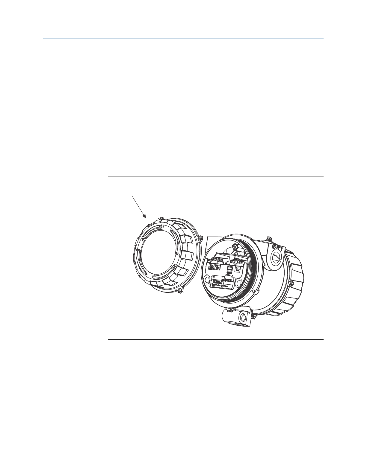
1. Power down the meter.
2. Using the strap wrench, loosen the grub screws and remove the transmitter end-
cap.
Transmitter with end-cap removedFigure 3-1:
Introduction to configuration and commissioning
A. Transmitter end‐cap
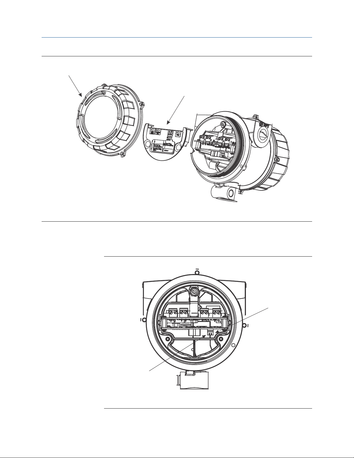
3. Using the hex key, remove the safety spacer.
Configuration and Use Manual 15
A
B
A
B
Introduction to configuration and commissioning
Transmitter with end-cap and safety spacer removedFigure 3-2:
A. Transmitter end‐cap
B. Safety spacer
4. Move the HART security switch to the OFF position (up).
The HART security switch is the switch on the left.
HART security switchFigure 3-3:
A. HART security switch
B. Unused
16 Micro Motion® Fork Density Meters (FDM)

5. Replace the safety spacer and end-cap.
6. Power up the meter.
3.4 Set the HART lock
If you plan to use a HART connection to configure the device, you can lock out all other
HART masters. If you do this, other HART masters will be able to read data from the device
but will not be able to write data to the device.
Restrictions
• This feature is available only when you are using the Field Communicator or AMS.
• This feature is available only with a HART 7 host.
Procedure
1. Choose Configure > Manual Setup > Security > Lock/Unlock Device.
2. If you are locking the meter, set Lock Option as desired.
Introduction to configuration and commissioning
Option Description
Permanent Only the current HART master can make changes to the device. The device will
remain locked until manually unlocked by a HART master. The HART master can
also change Lock Option to Temporary.
Temporary Only the current HART master can make changes to the device. The device will
remain locked until manually unlocked by a HART master, or a power-cycle or
device reset is performed. The HART master can also change Lock Option to Perma-
nent.
Lock All No HART masters are allowed to make changes to the configuration. Before
changing Lock Option to Permanent or Temporary, the device must be unlocked. Any
HART master can be used to unlock the device.
Postrequisites
To avoid future confusion or difficulties, ensure that the device is unlocked after you have
completed your tasks.
3.5 Restore the factory configuration
Display Not available
ProLink III Device Tools > Configuration Transfer > Restore Factory Configuration
Field Communicator Service Tools > Maintenance > Reset/Restore > Restore Factory Configuration
Configuration and Use Manual 17

Introduction to configuration and commissioning
Overview
Restoring the factory configuration returns the transmitter to a known operational
configuration. This may be useful if you experience problems during configuration.
Tip
Restoring the factory configuration is not a common action. You may want to contact Micro Motion
to see if there is a preferred method to resolve any issues.
18 Micro Motion® Fork Density Meters (FDM)

Configure process measurement
4 Configure process measurement
Topics covered in this chapter:
• Verify the calibration factors
• Configure line density measurement
• Configure temperature measurement
• Configure the pressure input
• Set up the API referral application
• Set up concentration measurement
• Set up flow rate measurement
4.1 Verify the calibration factors
Display Not available
ProLink III Device Tools > Calibration Data
Field Communicator Configure > Manual Setup > Calibration Factors
Overview
The calibration factors are used to adjust measurement for the unique traits of the sensor.
Your device was calibrated at the factory. However, you should verify that the calibration
factors that are configured in your device match the factory values.
Prerequisites
You will need the factory values for the calibration factors. These are provided in two
locations:
• The calibration certificate shipped with your meter
• The label inside the transmitter's end-cap
Important
If the transmitter is not the original component, do not use the values from the transmitter label.
Procedure
1. View the calibration factors that are stored in the device.
2. Compare them to the factory values.
• If the values match, no action is required.
• If the values do not match, contact Micro Motion customer service.
Configuration and Use Manual 19

Configure process measurement
Related information
Sample calibration certificate
4.1.1 Calibration factors
The original calibration factors are obtained from factory calibration, and are unique to
each device. They are used to adjust measurements for the specific physical properties of
the device.
The calibration certificate contains two sets of factors:
Density calibration
coefficients
Temperature
compensation coefficients
The calibration certificate also provides the results of the Known Density Verification
procedure that was performed at the factory.
For each calibration performed at the factory, the calibration certificate contains the data
used to calculate the calibration coefficients.
Related information
Sample calibration certificate
Define the relationship between density and the response
of your sensor
Adjust density measurement for the effect of temperature
on sensor response
4.2 Configure line density measurement
The density measurement parameters control how density is measured and reported.
• Configure Density Measurement Unit (Section 4.2.1)
• Configure Density Damping (Section 4.2.2)
• Configure Density Cutoff (Section 4.2.3)
• Configure two‐phase flow parameters (Section 4.2.4)
4.2.1 Configure Density Measurement Unit
Display OFF-LINE MAINT > OFF-LINE CONFG > UNITS > DENS
ProLink III Device Tools > Configuration > Process Measurement > Line Density > Density Unit
Field Communicator Configure > Manual Setup > Measurements > Density > Density Unit
Overview
Density Measurement Unit controls the measurement units that will be used in density
calculations and reporting.
20 Micro Motion® Fork Density Meters (FDM)

Configure process measurement
Restriction
If the API referral application is enabled, you cannot change the density measurement unit here. The
density measurement unit is controlled by the API table selection.
Procedure
Set Density Measurement Unit to the option you want to use.
The default setting for Density Measurement Unit is g/cm3 (grams per cubic centimeter).
Related information
Set up the API referral application
Options for Density Measurement Unit
The transmitter provides a standard set of measurement units for Density Measurement Unit.
Different communications tools may use different labels.
Options for Density Measurement UnitTable 4-1:
Label
Unit description
Specific gravity SGU SGU SGU
Grams per cubic centimeter G/CM3 g/cm3 g/Cucm
Grams per liter G/L g/l g/L
Grams per milliliter G/mL g/ml g/mL
Kilograms per liter KG/L kg/l kg/L
Kilograms per cubic meter KG/M3 kg/m3 kg/Cum
Pounds per U.S. gallon LB/GAL lbs/Usgal lb/gal
Pounds per cubic foot LB/CUF lbs/ft3 lb/Cuft
Pounds per cubic inch LB/CUI lbs/in3 lb/CuIn
Short ton per cubic yard ST/CUY sT/yd3 STon/Cuyd
Degrees API D API degAPI degAPI
Special unit SPECL special Spcl
Display (standard) ProLink III Field Communicator
Define a special measurement unit for density
Display Not available
ProLink III Device Tools > Configuration > Process Measurement > Line Density > Special Units
Field Communicator Configure > Manual Setup > Measurements > Special Units
Configuration and Use Manual 21

Configure process measurement
Overview
A special measurement unit is a user-defined unit of measure that allows you to report
process data in a unit that is not available in the transmitter. A special measurement unit is
calculated from an existing measurement unit using a conversion factor.
Procedure
1. Specify Density Special Unit Base.
2. Calculate Density Special Unit Conversion Factor as follows:
3. Enter Density Special Unit Conversion Factor.
4. Set User-Defined Label to the name you want to use for the density unit.
Density Special Unit Base is the existing density unit that the special unit will be based
on.
a. x base units = y special units
b. Density Special Unit Conversion Factor = x÷y
The original density value is divided by this conversion factor.
The special measurement unit is stored in the transmitter. You can configure the
transmitter to use the special measurement unit at any time.
Example: Defining a special measurement unit for density
You want to measure density in ounces per cubic inch.
1. Set Density Special Unit Base to g/cm3.
2. Calculate Density Special Unit Conversion Factor:
a. 1 g/cm3 = 0.578 oz/in3
b. 1÷0.578 = 1.73
3. Set Density Special Unit Conversion Factor to 1.73.
4. Set User-Defined Label to oz/in3.
4.2.2 Configure Density Damping
Display Not available
ProLink III Device Tools > Configuration > Process Measurement > Line Density > Density Damping
Field Communicator Configure > Manual Setup > Measurements > Density > Density Damping
Overview
Density Damping controls the amount of damping that will be applied to the line density
value.
22 Micro Motion® Fork Density Meters (FDM)

Configure process measurement
Damping is used to smooth out small, rapid fluctuations in process measurement. Damping
Value specifies the time period (in seconds) over which the transmitter will spread changes
in the process variable. At the end of the interval, the internal value will reflect 63% of the
change in the actual measured value.
Tip
Density damping affects all process variables that are calculated from line density.
Procedure
Set Density Damping to the value you want to use.
The default value is 1.6 seconds. The range is 0 to 60 seconds.
Interaction between Density Damping and Added Damping
When the mA output is configured to report density, both Density Damping and Added
Damping are applied to the reported density value.
Density Damping controls the rate of change in the value of the process variable in
transmitter memory. Added Damping controls the rate of change reported via the mA
output.
If mA Output Process Variable is set to Density, and both Density Damping and Added Damping are
set to non-zero values, density damping is applied first, and the added damping
calculation is applied to the result of the first calculation. This value is reported over the
mA output.
Related information
Interaction between mA Output Damping and process variable damping
4.2.3 Configure Density Cutoff
Display Not available
ProLink III Device Tools > Configuration > Process Measurement > Line Density > Density Cutoff Low
Field Communicator Configure > Manual Setup > Measurements > Density > Density Cutoff
Overview
Density Cutoff Low specifies the lowest density value that will be reported as measured. All
density values below this cutoff will be reported as 0.
Procedure
Set Density Cutoff Low to the value you want to use.
The default value is 0.2 g/cm³. The range is 0.0 g/cm³ to 0.5 g/cm³.
Configuration and Use Manual 23

Configure process measurement
4.2.4 Configure two-phase flow parameters
Display Not available
ProLink III Device Tools > Configuration > Process Measurement > Line Density
Field Communicator Configure > Manual Setup > Measurements > Density
Overview
The two-phase flow parameters control how the transmitter detects and reports twophase flow (gas in a liquid process or liquid in a gas process).
Note
Two-phase flow is sometimes referred to as slug flow.
Procedure
1. Set Two-Phase Flow Low Limit to the lowest density value that is considered normal in
your process.
Values below this will cause the transmitter to post Alert A105 (Two-Phase Flow).
Tip
Gas entrainment can cause your process density to drop temporarily. To reduce the
occurrence of two-phase flow alerts that are not significant to your process, set Two-Phase Flow
Low Limit slightly below your expected lowest process density.
You must enter Two-Phase Flow Low Limit in g/cm³, even if you configured another unit
for density measurement.
2. Set Two-Phase Flow High Limit to the highest density value that is considered normal in
your process.
Values above this will cause the transmitter to post Alert A105 (Two-Phase Flow).
Tip
To reduce the occurrence of two-phase flow alerts that are not significant to your process, set
Two-Phase Flow High Limit slightly above your expected highest process density.
You must enter Two-Phase Flow High Limit in g/cm³, even if you configured another
unit for density measurement.
3. Set Two-Phase Flow Timeout to the number of seconds that the transmitter will wait for
a two-phase flow condition to clear before posting the alert.
The default value for Two-Phase Flow Timeout is 0.0 seconds, meaning that the alert
will be posted immediately. The range is 0.0 to 60.0 seconds.
24 Micro Motion® Fork Density Meters (FDM)
 Loading...