

Micro Motion Manual: Field-Mount Transmitter - Model RFT9739 | Micro Motion Manuals & Guides

Model RFT9739
Field-Mount Transmitter
Instruction Manual
Version 3 Transmitters
February 2000


Model RFT9739
Copyright ©2000, Micro Motion, Inc. All rights res erved.
Micro Motion, ELITE, and ProLink are registered trademarks of Micro Motion, Inc.,
Boulder, Colorado. Rosemount and SMART FAMILY are registered tradema r k s of
Rosemount, Inc., Eden Prair i e, Minn eso ta . Fis her -Rosemount is a trademark o f
Fisher-Rosemount, C layton, Missouri. HART is a registered trademar k of the HART
Communication Foundation, Austin, Texas. Modbus is a registered tra dem ark of
Modicon, Inc., North Andover, Massachusetts. Tefzel is a registered trademark of E.I.
Du Pont de Nemours Co., Inc., Wilmington, Delaware.
Field-Mount Transmitter
Instruction Manual
Version 3 Transmitters
For technical assistance, phone the Micro Motion Customer
Service Department:
• In the U.S.A., phone 1-800-522-6277, 24 hours
• Outside the U.S.A., phone 30 3-530-8400, 24 hours
• In Europe, phone +31 (0) 318 549 443
• In Asia, phone 65-770-8155


Contents
1 Before You Begin
1.1 About this manual . . . . . . . . . . . . . . . . . . . . . . . . . . . . 1
1.2 About the transmitter . . . . . . . . . . . . . . . . . . . . . . . . . . 1
2 Getting Started
2.1 Hazardous area installations. . . . . . . . . . . . . . . . . . . . 3
Installations in Europe. . . . . . . . . . . . . . . . . . . . . . . . . 4
2.2 Configuration, calibration, and characterization . . . . . 4
2.3 Switch settings. . . . . . . . . . . . . . . . . . . . . . . . . . . . . . . 5
Security modes . . . . . . . . . . . . . . . . . . . . . . . . . . . . . . 5
Security mode 8. . . . . . . . . . . . . . . . . . . . . . . . . . . . . . 6
Communication settings . . . . . . . . . . . . . . . . . . . . . . . 9
Milliamp output scaling . . . . . . . . . . . . . . . . . . . . . . . . 9
3 Transmitter Mounting
3.1 General guidelines. . . . . . . . . . . . . . . . . . . . . . . . . . . . 11
3.2 Mounting to a wall . . . . . . . . . . . . . . . . . . . . . . . . . . . . 12
3.3 Mounting to an instrument pole. . . . . . . . . . . . . . . . . . 13
4 Power-Supply and Sensor Wiring
4.1 General guidelines. . . . . . . . . . . . . . . . . . . . . . . . . . . . 15
Installations in Europe. . . . . . . . . . . . . . . . . . . . . . . . . 17
4.2 Power supply and grounding. . . . . . . . . . . . . . . . . . . . 18
Power-supply options . . . . . . . . . . . . . . . . . . . . . . . . . 18
Wiring . . . . . . . . . . . . . . . . . . . . . . . . . . . . . . . . . . . . . 18
Grounding . . . . . . . . . . . . . . . . . . . . . . . . . . . . . . . . . . 19
4.3 Sensor wiring. . . . . . . . . . . . . . . . . . . . . . . . . . . . . . . . 21
Cable connections to sensor and transmitter . . . . . . . 21
. . . . . . . . . . . . . . . . . . . . . . . . . . . . . .
. . . . . . . . . . . . . . . . . . . . . . . . . . . . . . . . .
. . . . . . . . . . . . . . . . . . . . . . . . . .
. . . . . . . . . . . . .
1
3
11
15
RFT9739 Field-Mount Tra nsm it te r Instruction Manual
i

Contents
continued
5 Output Wiring
5.1 General guidelines. . . . . . . . . . . . . . . . . . . . . . . . . . . . 25
5.2 Maximum wire length. . . . . . . . . . . . . . . . . . . . . . . . . . 25
5.3 Primary and secondary mA outputs. . . . . . . . . . . . . . . 27
Connections for HART
5.4 Frequency/pulse output . . . . . . . . . . . . . . . . . . . . . . . . 30
Default configuration . . . . . . . . . . . . . . . . . . . . . . . . . . 31
Configuration for increased current . . . . . . . . . . . . . . . 31
Configuration for constant current . . . . . . . . . . . . . . . . 32
Configuration for open collector mode. . . . . . . . . . . . . 33
5.5 Control output . . . . . . . . . . . . . . . . . . . . . . . . . . . . . . . 35
Control output in open collector mode . . . . . . . . . . . . . 36
5.6 Peripheral device wiring. . . . . . . . . . . . . . . . . . . . . . . . 38
5.7 Pressure transmitter wiring . . . . . . . . . . . . . . . . . . . . . 44
5.8 Remote-zero switch . . . . . . . . . . . . . . . . . . . . . . . . . . . 46
5.9 RS-485 multidrop network . . . . . . . . . . . . . . . . . . . . . . 47
5.10 Bell 202 multidrop network. . . . . . . . . . . . . . . . . . . . . . 48
6Startup
6.1 Initialization . . . . . . . . . . . . . . . . . . . . . . . . . . . . . . . . . 51
6.2 Using the optional display . . . . . . . . . . . . . . . . . . . . . . 51
6.3 Custody transfer event registers . . . . . . . . . . . . . . . . . 56
6.4 Flowmeter zeroing . . . . . . . . . . . . . . . . . . . . . . . . . . . . 57
6.5 Totalizer control . . . . . . . . . . . . . . . . . . . . . . . . . . . . . . 60
6.6 Process measurement. . . . . . . . . . . . . . . . . . . . . . . . . 61
. . . . . . . . . . . . . . . . . . . . . . . . . . . . . . . . . . . . . . . . . .
Initialization with display. . . . . . . . . . . . . . . . . . . . . . . . 51
Adjusting the sight window. . . . . . . . . . . . . . . . . . . . . . 52
Process variables mode. . . . . . . . . . . . . . . . . . . . . . . . 52
Communication configuration mode . . . . . . . . . . . . . . 54
Zeroing procedure . . . . . . . . . . . . . . . . . . . . . . . . . . . . 57
Diagnosing zero failure . . . . . . . . . . . . . . . . . . . . . . . . 59
Additional information about flowmeter zeroing. . . . . . 59
. . . . . . . . . . . . . . . . . . . . . . . . . . . . . . . . . . .
®
communication devices. . . . . 29
25
51
ii
RFT9739 Field-Mou nt Tra nsm i t t er Instruction Manual

Contents
continued
7 Troubleshooting
7.1 General guidelines. . . . . . . . . . . . . . . . . . . . . . . . . . . . 63
7.2 Transmitter diagnostic tools. . . . . . . . . . . . . . . . . . . . . 64
Diagnostic LED . . . . . . . . . . . . . . . . . . . . . . . . . . . . . . 64
Fault outputs . . . . . . . . . . . . . . . . . . . . . . . . . . . . . . . . 65
Diagnostic messages . . . . . . . . . . . . . . . . . . . . . . . . . 65
7.3 Interrogation with a HART
7.4 Troubleshooting using the transmitter display. . . . . . . 68
Not configured. . . . . . . . . . . . . . . . . . . . . . . . . . . . . . . 68
Transmitter failure messages . . . . . . . . . . . . . . . . . . . 68
Overrange and sensor error messages. . . . . . . . . . . . 69
Slug flow . . . . . . . . . . . . . . . . . . . . . . . . . . . . . . . . . . . 69
Output saturated messages . . . . . . . . . . . . . . . . . . . . 69
Informational messages . . . . . . . . . . . . . . . . . . . . . . . 71
7.5 Power supply. . . . . . . . . . . . . . . . . . . . . . . . . . . . . . . . 73
7.6 Wiring . . . . . . . . . . . . . . . . . . . . . . . . . . . . . . . . . . . . . 73
7.7 Master reset. . . . . . . . . . . . . . . . . . . . . . . . . . . . . . . . . 74
7.8 Additional information about troubleshooting . . . . . . . 76
7.9 Customer service. . . . . . . . . . . . . . . . . . . . . . . . . . . . . 76
. . . . . . . . . . . . . . . . . . . . . . . . . . . . . . . .
®
device . . . . . . . . . . . . . . . 66
Appendixes
Appendix A RFT9739 Specifications . . . . . . . . . . . . . . . . . . 77
Appendix B Ordering Information. . . . . . . . . . . . . . . . . . . . . 85
Appendix C Theory of Operation . . . . . . . . . . . . . . . . . . . . . 87
Appendix D HART
Appendix E Label Maintenance and Replacement . . . . . . . 95
Appendix F Transmitter Version Identification. . . . . . . . . . . 97
Appendix G Replacing Older Transmitters. . . . . . . . . . . . . . 99
Appendix H Return Policy . . . . . . . . . . . . . . . . . . . . . . . . . . 105
®
Communicator Menu Trees. . . . . . . . . 91
63
Index
RFT9739 Field-Mount Tra nsm it te r Instruction Manual
. . . . . . . . . . . . . . . . . . . . . . . . . . . . . . . . . . . . . . . . . . . . . .
107
iii

Contents
continued
Tables
Table 2-1 Security modes . . . . . . . . . . . . . . . . . . . . . . . . . 6
Table 2-2 Communications configuration . . . . . . . . . . . . . 10
Table 4-1 Terminal designations . . . . . . . . . . . . . . . . . . . . 22
Table 5-1 Output wiring terminal designations . . . . . . . . . 26
Table 5-2 Peripheral wiring diagrams . . . . . . . . . . . . . . . . 38
Table 5-3 Sensors affected by pressure . . . . . . . . . . . . . . 44
Table 6-1 Display screens. . . . . . . . . . . . . . . . . . . . . . . . . 53
Table 6-2 Parameters that affect event registers . . . . . . . 56
Table 6-3 Effect of security modes on flowmeter zeroing . 59
Table 6-4 Effect of security modes on totalizer control . . . 60
Table 7-1 Conditions indicated by diagnostic LED . . . . . . 64
Table 7-2 Fault output levels. . . . . . . . . . . . . . . . . . . . . . . 65
Table 7-3 Using transmitter failure messages. . . . . . . . . . 68
Table 7-4 Using overrange and sensor error messages. . 70
Table 7-5 Using slug flow and output saturated messages 70
Table 7-6 Using informational messages . . . . . . . . . . . . . 72
Table 7-7 Normal resistance for flowmeter circuits . . . . . . 73
Table 7-8 Default values after a master reset . . . . . . . . . . 75
Tables in appendixes
Table G-1 Resistance values for determining RTD type . . 100
Table G-2 RE-01 to RFT9739 terminal conversions . . . . . 102
Table G-3 RFT9712 to RFT9739 terminal conversions . . . 103
iv
RFT9739 Field-Mou nt Tra nsm i t t er Instruction Manual

Contents
continued
Figures
Figure 1-1 RFT9739 exploded view. . . . . . . . . . . . . . . . . . 2
Figure 2-1 Hazardous area approvals tag . . . . . . . . . . . . . 3
Figure 2-2 Switches . . . . . . . . . . . . . . . . . . . . . . . . . . . . . . 5
Figure 3-1 RFT9739 dimensions . . . . . . . . . . . . . . . . . . . . 12
Figure 3-2 Instrument-pole mounting. . . . . . . . . . . . . . . . . 13
Figure 4-1 RFT9739 exploded view. . . . . . . . . . . . . . . . . . 16
Figure 4-2 Lockout clamp for CENELEC transmitters . . . . 17
Figure 4-3 Power-supply wiring terminals . . . . . . . . . . . . . 19
Figure 4-4a Grounding detail — typical . . . . . . . . . . . . . . . . 20
Figure 4-4b Grounding detail — European installations . . . 20
Figure 4-5 Wiring to ELITE
Figure 4-6 Wiring to F-Series, Model D, and DL sensors . 23
Figure 4-7 Wiring to Model DT sensors . . . . . . . . . . . . . . . 23
Figure 5-1 Output terminals . . . . . . . . . . . . . . . . . . . . . . . . 26
Figure 5-2 4-20 mA output performance . . . . . . . . . . . . . . 27
Figure 5-3 Primary and secondary mA output wiring. . . . . 28
Figure 5-4 HART
®
Communicator, ProLink® PC-Interface,
and AMS modem connections . . . . . . . . . . 29
Figure 5-5 Frequency/pulse output wiring . . . . . . . . . . . . . 31
Figure 5-6 Frequency/pulse output wiring for increased
current . . . . . . . . . . . . . . . . . . . . . . . . . . . . 31
Figure 5-7 Frequency/pulse output wiring for constant
current . . . . . . . . . . . . . . . . . . . . . . . . . . . . 32
Figure 5-8 Frequency/pulse output wiring for open
collector mode . . . . . . . . . . . . . . . . . . . . . . 34
Figure 5-9 Location of resistor R14 (R1) on output board . 34
Figure 5-10 Control output wiring. . . . . . . . . . . . . . . . . . . . . 35
Figure 5-11 Control output wiring for open collector mode . 37
Figure 5-12 Location of resistor R15 (R2) on output board . 37
Figure 5-13 Wiring to DMS. . . . . . . . . . . . . . . . . . . . . . . . . . 38
Figure 5-14a Wiring to DRT with LED . . . . . . . . . . . . . . . . . . 39
Figure 5-14b Wiring to DRT with LCD . . . . . . . . . . . . . . . . . . 39
Figure 5-15a Wiring to FMS-3 with LED . . . . . . . . . . . . . . . . 40
Figure 5-15b Wiring to FMS-3 with LCD . . . . . . . . . . . . . . . . 40
Figure 5-16 Wiring to NFC . . . . . . . . . . . . . . . . . . . . . . . . . . 41
Figure 5-17a Wiring to AC-powered NOC . . . . . . . . . . . . . . . 42
Figure 5-17b Wiring to DC-powered NOC . . . . . . . . . . . . . . . 42
Figure 5-18a Wiring to Model 3300 with screw-type or
solder-tail terminals . . . . . . . . . . . . . . . . . . 43
Figure 5-18b Wiring to Model 3300 with I/O cable. . . . . . . . . 43
Figure 5-19 Wiring to Model 3350 . . . . . . . . . . . . . . . . . . . . 43
Figure 5-20a Wiring to pressure transmitter — analog input . 45
Figure 5-20b Wiring to pressure transmitter — external
power, analog input . . . . . . . . . . . . . . . . . . 45
Figure 5-20c Wiring to pressure transmitter — digital
communications . . . . . . . . . . . . . . . . . . . . . 46
Figure 5-21 Wiring to remote-zero switch . . . . . . . . . . . . . . 46
Figure 5-22 RS-485 wiring . . . . . . . . . . . . . . . . . . . . . . . . . . 48
Figure 5-23 Typical HART
Figure 6-1 Diagnostic LED and zero button. . . . . . . . . . . . 58
®
CMF sensors . . . . . . . . . . . . 22
®
network wiring . . . . . . . . . . . . . 49
RFT9739 Field-Mount Tra nsm it te r Instruction Manual
v

Contents
continued
Figure 7-1 Diagnostic LED and communicator loops . . . . . 64
Figure 7-2 HART
®
Communicator, ProLink® PC-Interface,
and AMS modem connections . . . . . . . . . . 67
Figures in appendixes
Figure C-1 Coriolis mass flow sensor . . . . . . . . . . . . . . . . . 87
Figure D-1 On-line menu. . . . . . . . . . . . . . . . . . . . . . . . . . . 91
Figure E-1 Label number 3002168 . . . . . . . . . . . . . . . . . . . 95
Figure F-1 Switches on RFT9739 transmitters. . . . . . . . . . 97
Figure G-1 RFT9739 terminals . . . . . . . . . . . . . . . . . . . . . . 101
Figure G-2 RE-01 Remote Electronics Unit terminals. . . . . 102
Figure G-3 RFT9712 Remote Flow Transmitter terminals . 103
vi
RFT9739 Field-Mou nt Tra nsm i t t er Instr uc t io n M anual

1 Before You Begin
1.1 About this manual
1.2 About the transmitter
This instruction manual explains how to:
• Install the Micro Motion
use with Micro Motion Coriolis flow sensors, including instructions for:
-
Transmitter mounting
-
Power-supply, sensor, and output wiring
• Initialize the transmitter
• Diagnose and troubleshoot problems with the transmitter
For information about Micro Motion sensors, see the appropriate sensor
instruction manuals.
Instructions in this manual pertain to Version 3 transmitters. Do not use
this manual for transmitters shipped before January 1996. To identify the
transmitter version, see
Micro Motion sensors and transmitters with enhanced EMI immunity
comply with EMC directive 89/336/EEC and low-voltage directive
73/23/EEC, when properly installed in accordance with the guidelines
and instructions in this manual.
The Model RFT9739 transmitter is a microprocessor-based transmitter
for fluid process measurement. The transmitter works with Micro Motion
sensors to measure mass or volume flow, density, and temperature.
An optional display is available, and comes installed on the removable
housing cover. Scroll and Reset knobs on the cover enable the user to
perform the following operations (see
• View flow rate, density, temperature, mass and volume totals and
inventory levels, and status messages
• Set the transmitter's flow totalizers
• Reset communication paramete rs
• Zero the flowmeter
®
Model RFT9739 field-mount transmitter for
Appendix F
, page 97.
Section 6.2
, page 51):
Pow er-Supply and
Sensor Wiring
Output Wiring Startup TroubleshootingBefore You Begin Getting Started Mounting
Components of the transmitter are shown in
RFT9739 Field-Mount Tra nsm it te r Instruction Manual
Figure 1-1
, page 2.
1

continued
Before You Begin
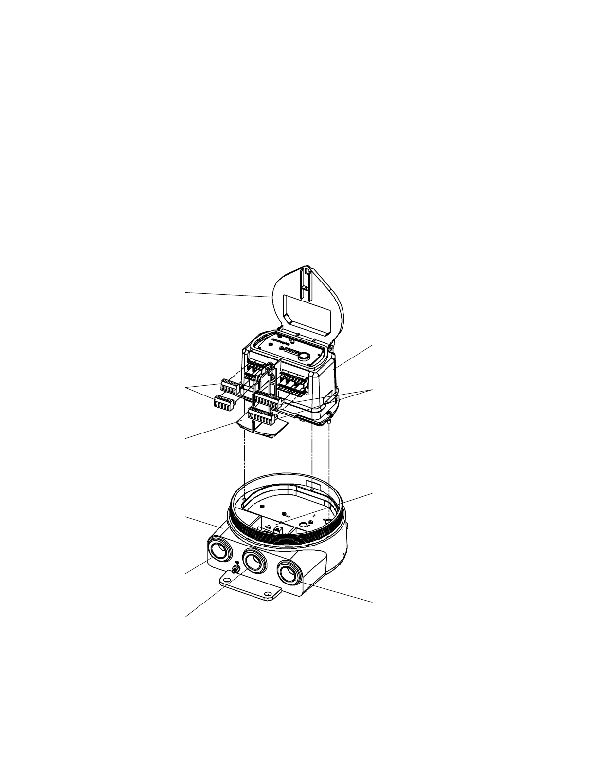
Figure 1-1. RFT9739 exploded view
Removable cover
of housing
Hinged cover of
electronics module
Diagnostic LED
Electronics modu le
Intrinsically safe
terminals for wiring
to sensor
Partition (safety barrier)
Must be in place during
operation of transmitter
Housing base
Switches 1 through 10
Zero button
Non-intrinsically safe
output termina l s
Power-supply wiring
and equipment ground
terminals
2
RFT9739 Field-Mou nt Tra nsm i t t er Instruction Manual

2 Getting Started
Hazardous area
approvals tag
2.1 Hazardous area installations
WARNING
Failure to comply with requirements for intrinsic
safety in a hazardous area could result in an
explosion.
• Install the transmitter in an environment that is
compatible with the hazardous area specified on the
approvals tag. See
• For intrinsically safe inst allati ons , use this docu me nt with
Micro Motion UL, CSA, or SAA installation instructions.
• For hazardous area installations in Europe, refer to
standard EN 60079-14 if nation al standards do not apply.
• Read the approvals tag before installing the RFT9739. The approvals
tag is attached to the transmitter housing. See
• For a complete list of UL, CSA, SAA, and European approvals, see
page 82.
• For intrinsically safe installations, use this manual with the appropriate
Micro Motion intrinsically safe installation instructions:
-
UL-D-IS Installation Instructions
-
CSA-D-IS Installation Instructions
-
SAA-D-IS Installation Instructions
• In Europe, refer to standard EN60079-14 if national standards do not
apply. To comply with CENELEC standards, see page 4.
Figure 2-1
.
Figure 2-1
.
Pow er-Supply and
Sensor Wiring
Output Wiring Startup TroubleshootingBefore You Begin Getting Started Mounting
Figure 2-1.
Hazardous area approvals
tag
RFT9739 Field-Mount Tra nsm it te r Instruction Manual
3

Getting Started
continued
Installations in Europe
2.2 Configuration, calibration, and characterization
To comply with CENELEC standards for hazardous area installations in
Europe, adhere to the following CENELEC conditions for safe use.
Cable glands and conduit seals
• Use 3/4"-14 NPT cable glands or conduit fittings, rated flameproof for
EEx d IIC areas and certified by an authorized test station. Flameproof
glands supplied by Micro Motion meet these requirements.
• Conduit openings that are not used should be sealed with blanking
plugs of type PLG 2.
• For installation in a nonhazardous area, cable glands or conduit fittings
that do not carry a flameproof rating are acceptable.
Potential equalization
To achiev e potential equalization, the RFT9739 ground conductor should
be connected to the appropriate ground terminals within the hazardous
area, using a potential equalizing line.
Output wiring
Nonintrinsically-safe connections between the RFT9739 and other
devices may be made
or equal to 250 V.
The following information explains the differences among configuration,
calibration, and characterization. Certain parameters might require
configuration
even when
only
to devices that maintain a voltage less than
calibration
is not necessary.
Configuration parameters
measurement units, flow direction, damping values, slug flow
parameters, and span values for the milliamp and frequency outputs. If
requested at time of order, the transmitter is configured at the factory
according to customer specifications.
Calibration
density, and temperature. Field calibration is optional.
Characterization
density, and temperature directly into transmitter memory. Calibration
factors can be found on the sensor serial number tag and on the
certificate that is shipped with the sensor.
For configuration, calibration, or characterization procedures, see one of
the following communications manuals:
Using the HART Communicator with Micro Motion Transmitters
•
Using ProLink Software with Micro Motion Transmitters
•
Using Modbus Protocol with Micro Motion Transmitters
•
You can also use Fisher-Rosemount™ Asset Management Solutions
(AMS) software for configuration, calibration, and characterization. For
more information, see the AMS on-line help.
A basic software tree for the HART Communicator is shown in
Appendix D
accounts for an individual sensor’s sensitivity to flow,
is the process of entering calibration factors for flow,
, page 91.
include items such as flowmeter tag,
4
RFT9739 Field-Mou nt Tra nsm i t t er Instruction Manual

Getting Started
continued
2.3 Switch settings
Security modes
Switches 1 through 10 on the electronics module control the following
transmitter functions:
• Baud rate
• Stop bits and parity
• Data bits, communication protocol, and physical layer
• mA outputs
• Zeroing method
• Write-protection of transmitter configuration
Switches 1 through 10 are illustrated in
Figure 2-2
, and described in the
following sections. Normally, switch settings do not require adjustment.
Switches 1, 2, and 3 are security switches, which enable the user to
disable flowmeter zeroing, disable resetting of totalizers, and writeprotect all configuration and calibration parameters.
Switch settings enable any of eight possible security modes. Different
modes determine which functions are disabled and whether
configuration and calibration parameters are write-protected. The
following functions can be disabled:
• Flowmeter zeroing using digital communications
• Flowmeter zeroing using the zero button and, if the transmitter has a
display, the Scroll and Reset knobs
• Totalizer reset, with flow, using digital communications
• Totalizer reset, with flow, using the Scroll and Reset knobs, if the
transmitter has a display
• Totalizer control, with zero flow, using digital communications
• Totalizer control, with zero flow, using the Scroll and Reset knobs, if the
transmitter has a display
• Ability to change configuration or calibration factors
Pow er-Supply and
Sensor Wiring
Table 2-1
are disabled for each security mode. Security modes 1 through 7 are
entered immediately when switches 1 through 3 are set.
For information about security mode 8, see pages 6 through 8.
Figure 2-2. Switches
RFT9739 Field-Mount Tra nsm it te r Instruction Manual
lists the parameters that are write-protected and functions that
Switches 1 through 10 at left
are shown in the OFF position.
Output Wiring Startup TroubleshootingBefore You Begin Getting Started Mounting
5

continued
Getting Started
Table 2-1. Security modes
Switch settings
Switch 1
Switch 2
Switch 3
Function/
parameter
Flowmeter
zeroing
Totalize r
control,
no flow
Totalize r
control,
with flow
Configuration and
calibration parameters
* C hanging the settings of switches 1, 2, and 3 does not immediately impl em ent security mode 8. For more information about
security mode 8, see pages 6 through 8.
Performed
with
Zero but t on or
Reset knob
HART or
Modbus
Scroll and
Reset knobs
HART or
Modbus
Scroll and
Reset knobs
HART or
Modbus
Mode
1
OFF
OFF
OFF
Mode
1
Mode
2
OFF
OFF
ON
Mode
2
Disabled Disabled Disabled Disabled Disabled Disabled Disabled
Disabled Disabled Disabled Disabled
Disabled Disabled Disabled Disabled Disabled Disabled Disabled
Mode
3
OFF
ON
OFF
Mode
3
Disabled Disabled Disabled Disabled
Disabled Disabled Disabled
Disabled Disabled Disabled Disabled Disabled Disabled
Write-
protected
Mode
4
OFF
ON
ON
Mode
4
Write-
protected
Mode
5
ON
OFF
OFF
Mode
5
Write-
protected
Mode
6
ON
OFF
ON
Mode
6
Write-
protected
Mode
7
ON
ON
OFF
Mode
7
Write-
protected
Mode
8*
ON
ON
ON
Mode
8
Write-
protected
Security mode 8
When transmitter security is set for mode 8, the transmitter meets
security requirements for custody transfer described in National Institute
of Standards and Technology (NIST) Handbook 44.
Once the transmitter is configured for security mode 8, the security
mode cannot be changed unless a master reset is performed. A master
reset causes all configuration parameters to return to their default
values, and
requires complete characterization and reconfiguration
of the trans m i tt e r.
If the user attempts to enter a new security mode or change the
transmitter configuration after entering security mode 8:
• Internal totalizers stop counting
• The frequency/pulse output goes to 0 Hz
• mA outputs go to 4 mA
• The optional display reads, "SECURITY BREACH; SENSOR OK"
• Custody transfer event registers record changes made to defined
configuration and calibration parameters. (For a list of these
parameters, see
Table 6-2
, page 56.)
The security breach continues, and totalizers and outputs remain
inactive, until the transmitter is reconfigured for security mode 8, or until
a master reset has been performed. Custody transfer ev ent registers are
not affected by a master reset.
• For information about event registers, see
• To perform a master reset, see instructions in
Section 6.3
Section 7.7
, page 56.
, page 74.
6
RFT9739 Field-Mou nt Tra nsm i t t er Instruction Manual

Getting Started
continued
Milliamp output trim, milliamp output test, and frequency/pulse output
test procedures cannot be performed after security mode 8 is entered.
Before entering security mode 8,
perform milliamp trim and/or test
procedures, if necessary , as described in any of the following manuals or
in AMS on-line help:
Using the HART Communicator with Micro Motion Transmitters
•
Using ProLink Software with Micro Motion Transmitters
•
Using Modbus Protocol with Micro Motion Transmitters
•
To enter security mode 8:
1. Note the position of switch 5.
2. Set switch 10 to the ON position. The diagnostic LED on the
transmitter electronics module flashes on 3 times and pauses, which
indicates the transmitter is in the configuration mode.
3. Set switches 1, 2, and 3 to the ON position.
4. Set switches 4, 5, and 6 to the OFF position.
5. Locate the ZERO button on the transmitter electronics module.
6. Press and hold the ZERO button for five seconds. The diagnostic LED
will remain on for two to three seconds to indicate security mode 8
has been entered.
7. Reset switch 5 to the desired position (as noted in Step 1).
8. Reset switch 10 to the OFF (OPERATE) position. The diagnostic LED
flashes on once per second (25% on, 75% off), which indicates the
transmitter is in the normal operating mode.
9. Leave switches 1, 2, and 3 in the ON position to remain in security
mode 8.
Pow er-Supply and
Sensor Wiring
To verify the transmitter is in security mode 8:
• If the transmitter has a display, use the Scroll knob to scroll through
process variable screens to event register screens. If event register
screens appear, the transmitter is in security mode 8. For more
information about using the Scroll knob and transmitter display, see
Section 6.2
, page 51.
• If the transmitter does not have a display:
1. Configure the transmitter.
2. Wait until the diagnostic LED blinks ON once per second.
3. Move switch 1, 2, or 3 to the OFF position.
4. If the diagnostic LED blinks ON 4 times per second, the transmitter
is in security mode 8.
Output Wiring Startup TroubleshootingBefore You Begin Getting Started Mounting
RFT9739 Field-Mount Tra nsm it te r Instruction Manual
7

Getting Started
continued
To make changes to configuration or calibration parameters once
security mode 8 is entered:
1. Set switches 1, 2, and 3 to the OFF position.
2. Make changes through digital communication or, if the transmitter has
a display, with the Scroll and Reset knobs (see "Communication
configuration mode," page 54). Custody transfer event registers
record changes made to defined configuration and calibration
parameters (see
Table 6-2
, page 56). For more information about
digital com m uni cati ons , see th e following ins truc tion m an ual s or AM S
on-line help:
Using the HART Communicator with Micro Motion Transmitters
•
Using ProLink Software with Micro Motion Transmitters
•
Using Modbus Protocol with Micro Motion Transmitters
•
3. Set switches 1, 2, and 3 to the ON position.
To reenter security mode 8:
If security mode 8 has been established previously, and the security
mode has been temporarily changed, it is not necessary to use the
ZERO button to reenter security mode 8. In such a case, resetting
switches 1, 2, and 3 to the ON position will reenter security mode 8
immediately.
If a master reset has been performed, it is necessary to use the ZERO
button method to reenter security mode 8. See procedure, page 7.
To change from security mode 8 to another security mode:
1. Perform a master reset (see
Section 7.7
, page 74, for master reset
procedure).
2. Perform characterization and reconfiguration procedures as
described in any of the following instruction manuals:
Using the HART Communicator with Micro Motion Transmitters
•
Using ProLink Software with Micro Motion Transmitters
•
Using Modbus Protocol with Micro Motion Transmitters
•
3. Set switches 1, 2, and 3 to the desired positions (see
Table 2-1
,
page 6).
8
RFT9739 Field-Mou nt Tra nsm i t t er Instruction Manual

Getting Started
continued
Communication settings
Switch 5 enables the user to choose the standard communication
configuration or user-defined parameters. With switch 10 in the ON
(CONFIG) position, switches 1 through 6 can be used for setting userdefined communication parameters.
Standard communication setting
To use the standard communication configuration, set switch 5 to the
STD COMM position. Setting the switch in this position establishes the
following communication parameters:
• HART protocol on the Bell 202 standard, at 1200 baud, on the primary
mA output
• Modbus protocol in RTU mode, at 9600 baud, on the RS-485 output
• 1 stop bit, odd parity
For RFT9739 software versions 3.6 and later, if switch 5 is in the STD
COMM position, and the RFT9739 has a display, an error message will
appear on the display when an attempt is made to change the
communication configuration using the RFT9739 display controls.
User-defined communication settings
To establish user-defined settings, set switches as instructed in
Table 2-2
, page 10. With switches 1 through 6, the user can set baud
rate; stop bits and parity; data bits, protocol, and physical layer. The
default settings are HART protocol, over RS-485, at 1200 baud, with
1 stop bit and odd parity.
Pow er-Supply and
Sensor Wiring
Milliamp output scaling
Switches 7, 8, and 9 allow the user to choose 0-20 mA or 4-20 mA
scaling for mA outputs, and upscale or downscale fault outputs.
Switch 7 defines the primary mA output scaling. Switch 8 defines the
secondary mA output scaling. Either switch may be set in the 0-20
position or the 4-20 position.
• The mA outputs are NAMUR compliant when switches 7 and 8 are in
the 4-20 position. See
Section 5.3
, page 27.
• Communication using the HART protocol over the primary mA output
requires switch 7 to be set in the 4-20 position.
• If switch 7 is in the 0-20 mA position, communication may be lost if
output is less than 2 mA. T o re-establish communication, move s witch 7
to the 4-20mA position.
Switch 9 defines the RFT9739 fault outputs. Fault outputs can be set for
downscale or upscale levels.
• If switch 9 is set to the DWNSCALE position, mA outputs go to 0 mA if
they produce a 0-20 mA current, or to 0-2 mA if they produce a
4-20 mA current; the frequency/pulse output goes to 0 Hz.
• If switch 9 is set to the UPSCALE position, mA outputs go to 22-24 mA;
the frequency/pulse output goes to 15-19 kHz.
• For more information, see "Fault outputs," page 65.
Output Wiring Startup TroubleshootingBefore You Begin Getting Started Mounting
RFT9739 Field-Mount Tra nsm it te r Instruction Manual
9

continued
Getting Started
Table 2-2. Communications configuration
Instructions
Before beginning, make note of the positions of switches 1, 2, and 3. Then, for each setting:
1. Begin with switch 10 in the CONFIG position, and switches 1 through 6 in the OFF position. The LED flashes ON 3 times and
pauses, which indicates th e transm i t te r is i n th e communication configuration mo de.
2. Set designated switches to the ON position as indicated below.
3. Press and hold the ZERO button for five seconds, until the LED remains ON for 3 seconds, which indicates the setting ha s
been accepted by the transmitter.
When done:
1. Reset switches 1, 2, and 3 to the appropriate positions.
2. Set switch 5 to the USER DEFINED position.
3. Set switches 4 and 6 to the OFF position.
4. Set switch 10 to the OPERATE position.
Note
If switches 4, 5, 6, and 10 are left in the ON position after configuration, a master reset will occur the next time power to the
transmitter is shut off and the n re st or ed. To avoid an unexpected mast er reset, make sure switches 4, 6, and 10 are left in the
OFF position after con fig urati on.
Baud rate
1200 baud ON ON
2400 baud ON ON ON
4800 baud ON ON
9600 baud ON ON ON
19,200 baud ON ON ON
38,400 baud ON ON
Stop bits and parity
1 stop bit, no parity ON
1 stop bit, odd parity ON ON
1 stop bit, even parity ON ON ON
2 stop bits, no parity ON ON
2 stop bits, odd parity ON ON ON
2 stop bits, even parity ON ON
Data bits, protocol, physical layer
HART on primary mA ON ON ON ON
HART on RS-485 ON ON ON
Modbus RTU mode (8 bits) on RS-485 ON ON
Modbus ASCII mode (7 bits) on RS-485 ON ON ON
Modbus RTU mode (8 bits) on RS-485
and HART on primary mA
Modbus ASCII mode (7 bits) on RS-485
and HART on primary mA
Switch
1
Switch
1
Switch
1
ON ON ON
ON ON ON ON
Switch
2
Switch
2
Switch
2
Switch
3
Switch
3
Switch
3
Switch
4
Switch
4
Switch
4
Switch
5
Switch
5
Switch
5
Switch
6
Switch
6
Switch
6
10
RFT9739 Field-Mou nt Tra nsm i t t er Instr uc t io n M anual
3 Transmitter Mounting
3.1 General guidelines
Follow these guidelines when installing the field-mount RFT9739
transmitter:
• Locate the transmitter where it is accessible for service and calibration.
• In hazardous areas, install the transmitter in a location that is specified
Section 2.1
in
• Total length of cable from the sensor to the transmitter must not exceed
1000 feet (300 meters).
• Locate the transmitter where the ambient temperature remains
between –22 and 131°F (–30 and 55°C). If the transmitter has a
display, the display might become difficult to read below 14°F (–10°C).
• Mount the transmitter to a stable, flat surface or instrument pole.
• The cover of the transmitter housing requires 11½ inches (292 mm)
clearance for removal. If the transmitter has a display, the cover
requires 13 3/16 inches (335 mm) clearance.
The base of the transmitter has three ¾-inch NPT female conduit
openings (see
keep the transmitter watertight.
, page 3.
Figure 3-1
, next page), which must remain sealed to
CAUTION
Failure to seal transmitter housing could cause a
short circuit, which w ould result i n measuremen t err or
or flowmeter failure.
Pow er-Supply and
Sensor Wiring
To avoid risk of condensation or excessive moisture
entering the transmitter housing, fully seal all conduit
openings when installing the transmitter.
• Install conduit that allows a complete seal with the conduit openings.
• If possible, orient the transmitter with its conduit openings pointed
downward. If this is not possible, seal the conduit to prevent
condensation and other moisture from entering the housing.
• To comply with CENELEC standards for hazardous area installations in
Europe:
-
Use cable glands or conduit fittings rated flameproof for EEx d IIC
areas and certified by an authorized test station. Flameproof glands
supplied by Micro Motion meet these requirements.
-
Conduit openings that are not used should be sealed with blanking
plugs of type PLG 2.
-
For installation in a nonhazardous area, cable glands or conduit
fittings that do not carry a flameproof rating are acceptable.
• If the transmitter has a display, the display will be right-side-up only if
the transmitter is oriented with its conduit openings pointed downward.
RFT9739 Field-Mount Tra nsm it te r Instruction Manual
Output Wiring Startup TroubleshootingBefore You Begin Getting Started Mounting
11
Transmitter Mounting
continued
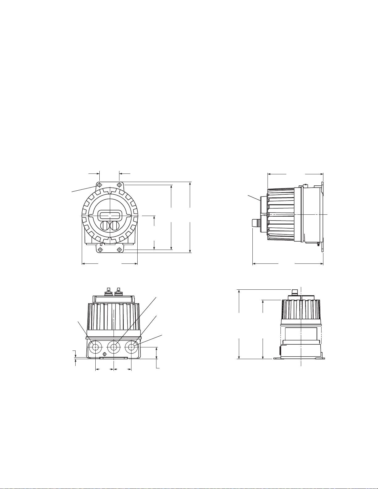
3.2 Mounting to a wall
Figure 3-1. RFT9739 dimensions
4X Ø
inches
(mm)
2 13/16
(71)
23/64
(9)
Dimensions in
Follow these guidelines and refer to
Figure 3-1
to mount the transmitter
to a wall or other flat, rigid surface.
• Use four 5/16-inch diameter (or M8) bolts and nuts to mount the
transmitter to a wall or other flat, rigid surface. Use bolts and nuts that
can withstand the process environment. Micro Motion does not supply
bolts or nuts (such bolts and nuts are available as an option).
• To minimize stress on the housing, secure all four mounting bolts to the
same structure, which should be flat and should not vibrate or move
excessively. Do not secure bolts to separate girders, beams, or wall
studs, which can move independently.
7 19/64
(185)
Optional
display
8 3/8
9 11/64
(213)
4 33/64
(115)
(233)
Sensor cable
conduit opening
3/16
(5)
7 15/64
(184)
2 3/8
(60)
2 3/8
(60)
Power-supply wiring
conduit opening
Output wiring
conduit opening
3x
3/4"-14 NPT
conduit opening
1 17/32
(39)
9 1/8
(232)
Removal of cover required for
access to wiring compartments
With
display
13 3/16
(335)
Without
display
11 1/2
(292)
12
RFT9739 Field-Mou nt Tra nsm i t t er Instr uc t io n M anual
Transmitter Mounting
continued
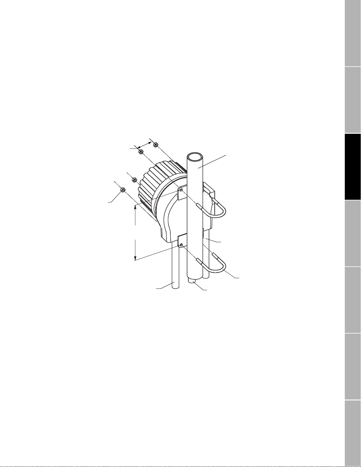
3.3 Mounting to an instrument pole
Figure 3-2. Instrument-pole mounting
Dimensions in
inches
(mm)
4X
5/16
(8)
2X
2 13/16
(71)
Follow these guidelines and refer to
Figure 3-2
to mount the transmitter
to an instrument pole:
• Use two 5/16-inch U-bolts for 2-inch pipe, and four matching nuts, to
mount the transmitter to a rigid instrument pole. Use U-bolts and nuts
that can withstand the process environment. Micro Motion does not
supply U-bolts or nuts.
• The instrument pole should extend at least 12 inches (305 mm) from a
rigid base, and be no more than 2 inches (50.8 mm) in diameter.
2-inch pipe
Pow er-Supply and
Sensor Wiring
2X
8 3/8
(213)
Output wiring
conduit
Sensor cable
wiring conduit
Power-supply
wiring conduit
5/16"-18 U-bolt
2X
for 2-inch pipe
Output Wiring Startup TroubleshootingBefore You Begin Getting Started Mounting
RFT9739 Field-Mount Tra nsm it te r Instruction Manual
13

14
RFT9739 Field-Mou nt Tra nsm i t t er Instr uc t io n M anual
4 Power-Supply and Sensor
Wiring
4.1 General guidelines
WARNING
Failure to comply with requirements for intrinsic
safety in a hazardous area could result in an
explosion.
Sensor wiring is intrinsically safe.
• Keep intrinsically safe sensor wiring separated from
power-supply wiring and output wiring.
• For intrinsically safe sensor inst allations, use this
document with Micro Motion UL, CSA, or SAA installat ion
instructions.
• For hazardous area installations in Europe, refer to
standard EN 60079-14 if nation al standards do not apply.
• Make sure the safety barrier partition is in place before
operating the transmitter.
CAUTION
Failure to seal transmitter housing and sensor
junction box could cause a short circuit, which would
result in measurement error or flowmeter failure.
To avoid risk of condensation or excessive moisture in the
junction box or transmitter housing:
• Seal all conduit openings.
• Install drip legs in cable or conduit.
• Ensure integrity of gaskets and O-rings, and fully tighten
all covers.
Pow er-Supply and
Sensor Wiring
Output Wiring Startup TroubleshootingBefore You Begin Getting Started Mounting
A removable partition on the electronics module keeps intrinsically safe
wiring to the sensor separated from nonintrinsically safe output wiring.
The module has a hinged, clear plastic cover. To access power-supply
wiring terminals, unlatch the cover of the module, then remove the
partition.
Figure 4-1
•
the sensor, output wiring terminals, and power-supply wiring terminals.
• Terminal blocks may be unplugged from the module for easier
installation of wiring.
• Install cable and wiring to meet local code requirements.
• A switch may be installed in the power-supply line. For compliance with
low-voltage directive 73/23/EEC, a switch in close proximity to the
transmitter is required for AC-powered transmitters.
• Do not install AC power cable or unfiltered DC power cable in the same
conduit or cable tray as sensor cable or output wiring.
RFT9739 Field-Mount Tra nsm it te r Instruction Manual
, page 16, shows the locations of the terminals for wiring to
15
continued
Power-Supply and Sensor Wiring
Figure 4-1. RFT9739 exploded view
Hinged cover of
electronics module
The base of the transmitter has three ¾-inch NPT female conduit
openings, indicated in
Figure 4-1
, which must rem ain seal ed to k eep the
transmitter watertight.
• Use conduit that allows a complete seal with the conduit openings.
• If possible, orient the transmitter with its conduit openings pointed
downward. Seal the conduit to prevent condensation and other
moisture from entering the housing.
• To comply with requirements for explosion-proof installations approved
by UL or CSA, install approved explosion-proof conduit seals on all
three conduit openings.
• To comply with CENELEC requirements for installations in Europe, see
page 17.
Intrinsically safe
terminals for wiring
to sensor
Partition (safety barrier)
Must be in place during
operation of transmitter
Housing base
Sensor wiring
conduit opening
Power-supply
conduit opening
Electronics module
Non-intrinsically safe
output terminals
Power-supply wiring
and equipment ground
terminals
Output wiring
conduit opening
16
RFT9739 Field-Mou nt Tra nsm i t t er Instr uc t io n M anual
Power-Supply and Sensor Wiring
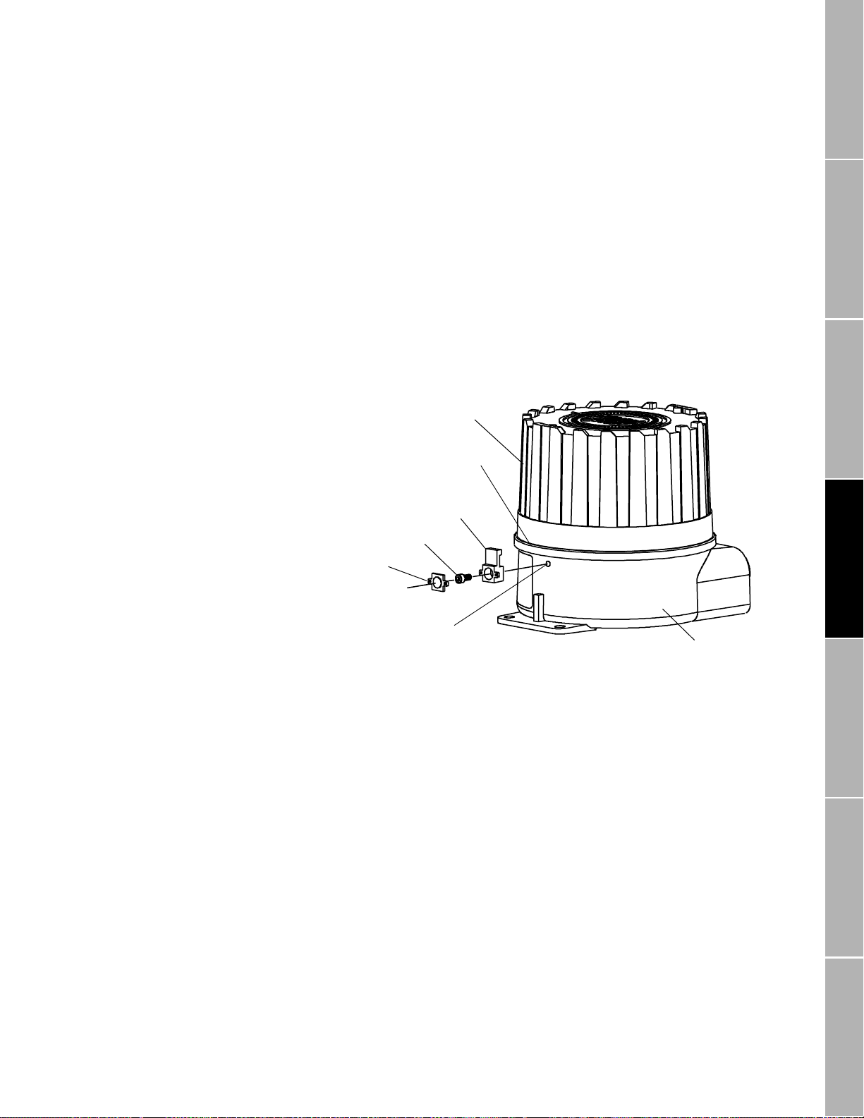
Housing cover
Lip
Clamp
Mounting screw
Cap
Threaded hole
Housing base
continued
Installations in Europe
Figure 4-2.
Lockout clamp for
CENELEC transmitters
To comply with CENELEC standards for hazardous area installations in
Europe, adhere to the following CENELEC conditions for safe use:
• Use 3/4"-14 NPT cable glands or conduit fittings, rated flameproof for
EEx d IIC areas and certified by an authorized test station. Flameproof
glands supplied by Micro Motion meet these requirements.
• Conduit openings that are not used should be sealed with blanking
plugs of type PLG 2.
• For installation in a nonhazardous area, cable glands or conduit fittings
that do not carry a flameproof rating are acceptable.
A CENELEC-compliant RFT9739 includes a lockout clamp on the
transmitter housing. See
Figure 4-2
. The clamp adds secondary
protection against accessing the power-supply terminals, and is required
to meet CENELEC standards.
Pow er-Supply and
Sensor Wiring
RFT9739 Field-Mount Tra nsm it te r Instruction Manual
Output Wiring Startup TroubleshootingBefore You Begin Getting Started Mounting
17

Power-Supply and Sensor Wiring
continued
4.2 Power supply and grounding
Power-supply options
Wiring
CAUTION
Incorrect vol tage, or install ation with po wer s upply on,
will cause transmitter damage or failure.
• Turn off power before installing transmitter.
• Match power-supply voltage with voltage indicated in
transmitter power terminals compartment.
The AC transmitter accepts an 85 to 250 VAC power supply. The DC
transmitter accepts a 12 to 30 VDC power supply.
• A label inside the power-supply wiring compartment indicates the
correct power-supply voltage.
Figure 4-3
•
terminals in the base of the transmitter housing.
• A lockout clamp on the transmitter housing (see
provides secondary protection against accessing the power-supply
terminals, and is required by CENELEC.
To install power-supply wiring, follow these steps:
1. To access power-supply wiring, unlatch the hinged cover of the
module, then remove the partition that separates intrinsically safe
sensor wiring from non-intrinsically safe output wiring.
2. Make input power connections at the two labeled terminals, as
indicated in
labeled as follows:
• If the terminals are labeled "L" (line) and "N" (neutral), install an
85 to 250 VAC power supply.
• If the terminals are labeled "+" (positive) and "–" (negative), install a
12 to 30 VDC power supply.
3. Ground the transmitter as instructed on page 19.
(next page) shows the location of power-supply wiring
Figure 4-3
Figure 4-2
(next page). The power supply terminals are
, page 17)
18
RFT9739 Field-Mou nt Tra nsm i t t er Instr uc t io n M anual

Power-Supply and Sensor Wiring
Equipment
ground
Power-supply conduit opening
Equipment
ground
Transmitter
power rating
Terminal
labels
85-250 VAC 50/60 H z L N
12-30 VDC +
−
Figure 4-3.
Power-supply wiring
terminals
continued
Grounding
WARNING
Failure to comply with requirements for intrinsic
safety in a hazardous area could result in an
explosion.
• T he transmitter must be properly grounded.
• Follow the instructions below to ground the transmitter.
• For hazardous area installations in Europe, refer to
standard EN 60079-14 if nation al standards do not apply.
To ensure proper grounding:
• If the installation must comply with UL, CSA, or SAA standards, refer to
the instructions in one of the following Micro Motion documents:
-
UL-D-IS Installation Instructions
-
CSA-D-IS Installation Instructions
-
SAA-D-IS Installation Instructions
• In most installations, install grounding as illustrated in
(next page).
• For installations in Europe, and to comply with CENELEC standards,
install grounding as illustrated in
Figure 4-4b
(next page).
• To achieve potential equalization and comply with CENELEC
standards for hazardous area installations in Europe, the RFT9739
external ground terminal (see
Figure 4-4b
) should be connected to the
appropriate ground terminals within the hazardous area, using a
potential equalizing line.
Figure 4-4a
Pow er-Supply and
Sensor Wiring
Output Wiring Startup TroubleshootingBefore You Begin Getting Started Mounting
RFT9739 Field-Mount Tra nsm it te r Instruction Manual
19
continued
Power-Supply and Sensor Wiring
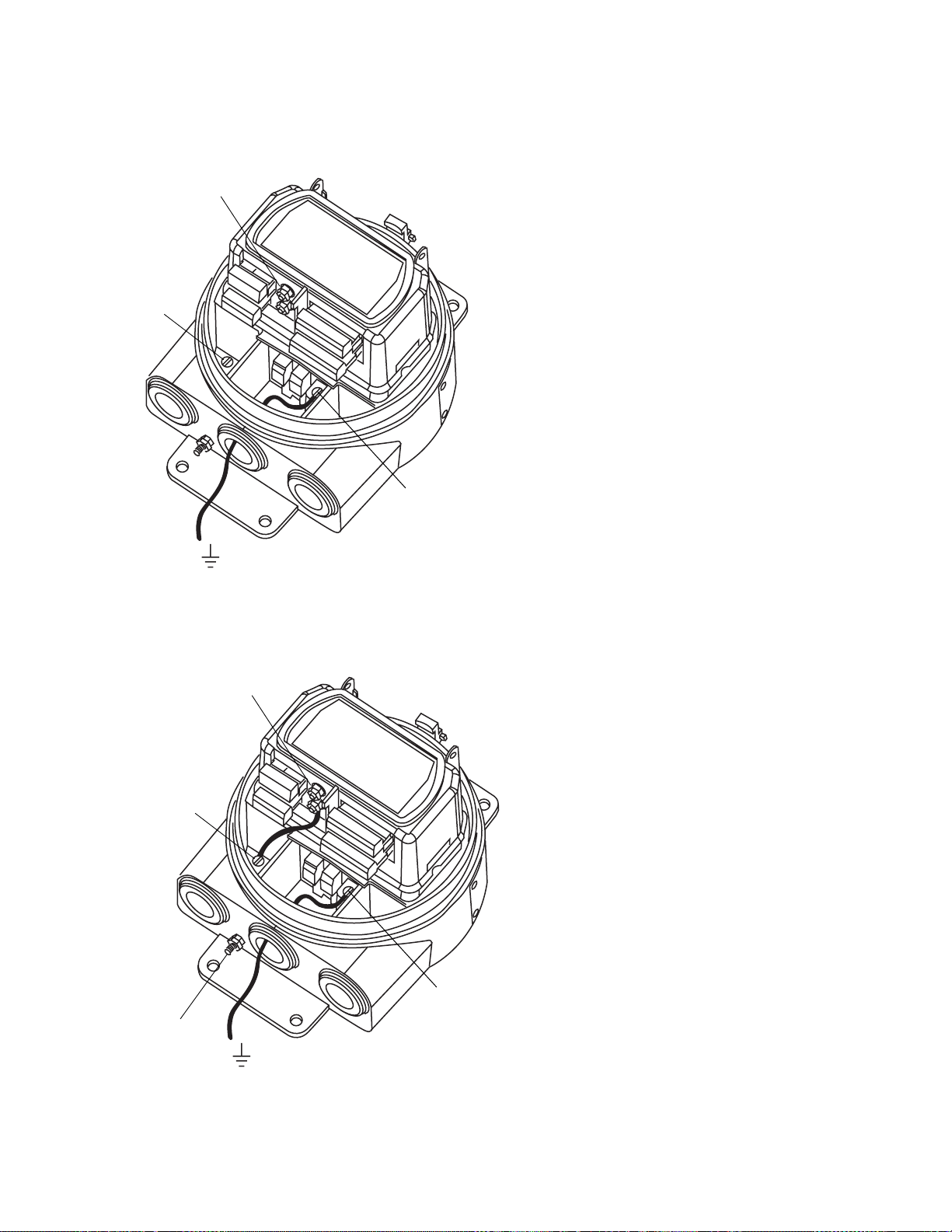
Figure 4-4a. Grounding detail — typical
I.S. ground
terminals
Internal
case ground
terminal
Power ground
terminal
Earth ground
Figure 4-4b. Grounding detail — European installations
I.S. ground
terminals
If national standards are not in e ffect, adhere to
these guidelines for grounding:
• Use copper wire, 14 AWG (2.5 mm²) or larger
wire size.
• Keep all ground leads as short as pos si ble, less
than 1 ohm impe dance.
• Connect I.S. ground terminals di r ect l y to in te rnal
case ground termi nal.
• Connect ground lead from power ground terminal
directly to earth ground.
• Follow plant standards, instead of this standard, if
a separate high-integrit y in trinsically safe ground
scheme is used.
Internal
case ground
terminal
External ground
terminal
20
Earth ground
Power ground
terminal
If national standards ar e not in effect, adhere to
these guidelines for grounding:
• Use copper wire, 14 AWG (2.5 mm²) or larger
wire size.
• Keep all ground leads as short as possible, less
than 1 ohm impedance.
• A factory-installed ground wire, connecting the
I.S. ground and internal case-ground terminals,
must remain i n p l ace.
• Connect ground lead from power ground terminal
directly to earth ground.
• Follow plant standards, instead of this standard, if
a separate high-integr ity intrinsically safe ground
scheme is used.
• To achieve potential equalization and comply with
CENELEC standar ds for hazardous area
installations in Europe, connect the external
ground terminal to the appropriate ground
terminals withi n t he hazardous area, using a
potential equalizing line.
• For hazardous area installation in Europe, use
standard EN 60079-1 4 as a guideline.
RFT9739 Field-Mou nt Tra nsm i t t er Instr uc t io n M anual
 Loading...