

Manual: FDM Meters with Foundation Fieldbus Configuration and Use Manual | Micro Motion
Table of contents
 Loading...
Micro Motion Manual: FDM Meters with Foundation Fieldbus Configuration and Use Manual | Micro Motion Manuals & Guides
Configuration and Use Manual
MMI-20024640, Rev AA
June 2014
Micro Motion® Fork Density Meters (FDM) with
Foundation™ Fieldbus
Configuration and Use Manual

Safety and approval information
This Micro Motion product complies with all applicable European directives when properly installed in accordance with the
instructions in this manual. Refer to the EC declaration of conformity for directives that apply to this product. The EC declaration of
conformity, with all applicable European directives, and the complete ATEX Installation Drawings and Instructions are available on
the internet at www.micromotion.com or through your local Micro Motion support center.
Information affixed to equipment that complies with the Pressure Equipment Directive can be found on the internet at
www.micromotion.com/documentation.
For hazardous installations in Europe, refer to standard EN 60079-14 if national standards do not apply.
Emerson Flow customer service
Email:
• Worldwide: flow.support@emerson.com
• Asia-Pacific: APflow.support@emerson.com
Telephone:
North and South America Europe and Middle East Asia Pacific
United States 800-522-6277 U.K. 0870 240 1978 Australia 800 158 727
Canada +1 303-527-5200 The Netherlands +31 (0) 318 495 555 New Zealand 099 128 804
Mexico +41 (0) 41 7686 111 France 0800 917 901 India 800 440 1468
Argentina +54 11 4837 7000 Germany 0800 182 5347 Pakistan 888 550 2682
Brazil +55 15 3413 8000 Italy 8008 77334 China +86 21 2892 9000
Venezuela +58 26 1731 3446 Central & Eastern +41 (0) 41 7686 111 Japan +81 3 5769 6803
Russia/CIS +7 495 981 9811 South Korea +82 2 3438 4600
Egypt 0800 000 0015 Singapore +65 6 777 8211
Oman 800 70101 Thailand 001 800 441 6426
Qatar 431 0044 Malaysia 800 814 008
Kuwait 663 299 01
South Africa 800 991 390
Saudia Arabia 800 844 9564
UAE 800 0444 0684

Contents
Contents
Part I Getting Started
Chapter 1 Before you begin ............................................................................................................3
1.1 About this manual ....................................................................................................................... 3
1.2 Model codes and device types ..................................................................................................... 3
1.3 Communications tools and protocols .......................................................................................... 4
1.4 Additional documentation and resources .................................................................................... 5
Chapter 2 Quick start .....................................................................................................................7
2.1 Power up the transmitter .............................................................................................................7
2.2 Check meter status ......................................................................................................................7
2.3 Make a startup connection to the transmitter ..............................................................................8
Part II Configuration and commissioning
Chapter 3 Introduction to configuration and commissioning ....................................................... 11
3.1 Default values ............................................................................................................................11
3.2 Enable access to the off-line menu of the display ....................................................................... 11
3.3 Place function blocks in Out of Service mode .............................................................................12
3.4 Restore the factory configuration .............................................................................................. 12
Chapter 4 Integrate the meter with the network ..........................................................................13
4.1 Assign function block channels to transducer block channels .................................................... 13
4.2 Configure AI Linearization .............................................................................................................14
4.3 Configure process alert limits for the AI blocks .......................................................................... 16
4.4 Configure the timeout for Field Diagnostic alerts .......................................................................17
Chapter 5 Configure process measurement ..................................................................................19
5.1 Verify the calibration factors ......................................................................................................19
5.1.1 Calibration factors ...................................................................................................... 20
5.2 Configure line density measurement ........................................................................................ 20
5.2.1 Configure Density Measurement Unit ................................................................................21
5.2.2 Configure Density Damping ............................................................................................ 23
5.2.3 Configure Density Cutoff ................................................................................................ 23
5.2.4 Configure two-phase flow parameters ........................................................................24
5.3 Configure temperature measurement .......................................................................................25
5.3.1 Configure Temperature Measurement Unit ........................................................................ 25
5.3.2 Configure Temperature Damping .....................................................................................26
5.3.3 Configure Temperature Input .......................................................................................... 27
5.4 Configure the pressure input ..................................................................................................... 29
5.4.1 Configure the pressure input using a fieldbus host ......................................................29
5.4.2 Options for Pressure Measurement Unit ........................................................................... 30
5.5 Set up the API referral application ..............................................................................................31
5.5.1 Set up the API referral application using ProLink III ...................................................... 31
5.5.2 Set up the API referral application using a fieldbus host ...............................................35
5.6 Set up concentration measurement .......................................................................................... 39
Configuration and Use Manual i

Contents
5.6.1 Preparing to set up concentration measurement ........................................................39
5.6.2 Set up concentration measurement using ProLink III ...................................................40
5.6.3 Using equations to calculate specific gravity, °Baumé, °Brix, °Plato, and °Twaddell ......47
5.6.4 Matrix switching ......................................................................................................... 48
Chapter 6 Configure device options and preferences ....................................................................51
6.1 Configure the transmitter display .............................................................................................. 51
6.1.1 Configure the language used for the display ............................................................... 51
6.1.2 Configure the process variables and diagnostic variables shown on the display ...........52
6.1.3 Configure the number of decimal places (precision) shown on the display ..................53
6.1.4 Configure the refresh rate of data shown on the display ..............................................53
6.1.5 Enable or disable automatic scrolling through the display variables ............................ 54
6.2 Enable or disable operator actions from the display ...................................................................55
6.2.1 Enable or disable the Acknowledge All Alerts display command ....................................... 55
6.3 Configure security for the display menus .................................................................................. 56
6.4 Configure alert handling ............................................................................................................57
6.4.1 Configure Fault Timeout .................................................................................................57
6.4.2 Configure Status Alert Severity ........................................................................................58
6.5 Configure informational parameters ......................................................................................... 60
Chapter 7 Completing the configuration ......................................................................................63
7.1 Back up transmitter configuration ............................................................................................. 63
7.2 Return function blocks to In Service (Auto) mode ......................................................................63
Part III Operations, maintenance, and troubleshooting
Chapter 8 Transmitter operation ................................................................................................. 67
8.1 Record the process variables ..................................................................................................... 67
8.2 View process variables ...............................................................................................................67
8.2.1 View process variables using the display .....................................................................67
8.2.2 View process variables and other data using ProLink III ............................................... 68
8.3 View and acknowledge status alerts .......................................................................................... 69
8.3.1 View and acknowledge alerts using the display .......................................................... 69
8.3.2 View and acknowledge alerts using ProLink III .............................................................71
8.3.3 View alerts using a fieldbus host ................................................................................. 72
8.3.4 Alert data in transmitter memory ............................................................................... 72
Chapter 9 Measurement support ................................................................................................. 75
9.1 Perform the Known Density Verification procedure ................................................................... 75
9.1.1 Perform the Known Density Verification procedure using the display ......................... 75
9.1.2 Perform the Known Density Verification procedure using ProLink III ........................... 76
9.1.3 Perform the Known Density Verification procedure using a fieldbus host ....................77
9.2 Adjust density measurement with Density Offset or Density Meter Factor ......................................... 78
9.3 Perform density offset calibration ..............................................................................................80
9.3.1 Perform density offset calibration using the display .................................................... 80
9.3.2 Perform density offset calibration using ProLink III ......................................................81
9.3.3 Perform density offset calibration using a fieldbus host .............................................. 83
9.4 Adjust temperature measurement with Temperature Offset or Temperature Slope ........................... 84
9.5 Perform temperature calibration ...............................................................................................85
9.5.1 Perform temperature calibration using the display ..................................................... 85
9.5.2 Perform temperature calibration using ProLink III ....................................................... 86
9.5.3 Perform temperature calibration using a fieldbus host ................................................87
ii Micro Motion® Fork Density Meters (FDM) with Foundation™ Fieldbus

Contents
9.6 Adjust concentration measurement with Trim Offset ...................................................................89
9.7 Adjust concentration measurement with Trim Offset and Trim Slope ............................................. 90
9.8 Set up user-defined calculations ................................................................................................ 92
9.8.1 Equations used in user-defined calculations ................................................................94
9.8.2 Measurement units used in user-defined calculations ................................................. 95
Chapter 10 Troubleshooting .......................................................................................................... 97
10.1 Quick guide to troubleshooting .................................................................................................97
10.2 Check power supply wiring ........................................................................................................98
10.3 Check grounding .......................................................................................................................99
10.4 Status LED states ....................................................................................................................... 99
10.5 Status alerts, causes, and recommendations ........................................................................... 100
10.6 Density measurement problems ............................................................................................. 105
10.7 Temperature measurement problems .....................................................................................106
10.8 API referral problems ...............................................................................................................107
10.9 Concentration measurement problems ...................................................................................107
10.10 Check sensor-to-transmitter wiring ......................................................................................... 108
10.11 Check the cutoffs .................................................................................................................... 109
10.12 Check for two-phase flow (slug flow) .......................................................................................109
10.13 Check the drive gain ................................................................................................................ 109
10.13.1 Collect drive gain data .............................................................................................. 110
10.14 Check the pickoff voltage ........................................................................................................ 111
10.14.1 Collect pickoff voltage data ...................................................................................... 111
10.15 Check for internal electrical problems ..................................................................................... 111
Appendices and reference
Appendix A Calibration certificate ................................................................................................ 113
A.1 Sample calibration certificate .................................................................................................. 113
Appendix B Using the transmitter display ..................................................................................... 115
B.1 Components of the transmitter interface ................................................................................ 115
B.2 Use the optical switches .......................................................................................................... 116
B.3 Access and use the display menu system .................................................................................117
B.3.1 Enter a floating-point value using the display ............................................................118
B.4 Display codes for process variables ..........................................................................................122
B.5 Codes and abbreviations used in display menus ...................................................................... 122
Appendix C Using ProLink III with the transmitter .........................................................................135
C.1 Basic information about ProLink III ...........................................................................................135
C.2 Connect with ProLink III ........................................................................................................... 136
C.2.1 Connection types supported by ProLink III ................................................................ 136
C.2.2 Connect with ProLink III to the service port ............................................................... 136
Appendix D Foundation™ fieldbus resource block and transducer blocks ....................................... 139
D.1 Resource block ........................................................................................................................ 139
D.2 Transducer blocks and views ................................................................................................... 144
D.2.1 Measurement transducer block and related information .......................................... 145
D.2.2 Calibration transducer block and related information ............................................... 150
D.2.3 Diagnostic transducer block and related information ................................................154
D.2.4 Device Information transducer block and related information .................................. 164
D.2.5 Local Display transducer block and related information ............................................ 169
D.2.6 API Referral transducer block and related information .............................................. 176
Configuration and Use Manual iii

Contents
D.2.7 Concentration Measurement transducer block and related information ................... 182
D.2.8 Density Viscosity Meter transducer block and related information ............................192
Appendix E Concentration measurement matrices, derived variables, and process variables ........ 211
E.1 Standard matrices for the concentration measurement application ........................................ 211
E.2 Concentration measurement matrices available by order ........................................................212
E.3 Derived variables and calculated process variables .................................................................. 214
iv Micro Motion® Fork Density Meters (FDM) with Foundation™ Fieldbus

Part I
Getting Started
Chapters covered in this part:
• Before you begin
• Quick start
Getting Started
Configuration and Use Manual 1

Getting Started
2 Micro Motion® Fork Density Meters (FDM) with Foundation™ Fieldbus

1 Before you begin
Topics covered in this chapter:
• About this manual
• Model codes and device types
• Communications tools and protocols
• Additional documentation and resources
1.1 About this manual
This manual provides information to help you configure, commission, use, maintain, and
troubleshoot the Micro Motion Fork Density Meter (FDM).
The following version of the FDM is documented in this manual: Fork Density Meter with
Foundation Fieldbus.
Before you begin
See Micro Motion® Fork Density Meters: Configuration and Use Manual for the following
versions of the FDM:
• Fork Density Meter with Analog Outputs
• Fork Density Meter with Analog Output and Discrete Output
• Fork Density Meter with Time Period Signal Output
Important
This manual assumes that your meter has been installed correctly and completely, according to the
instructions in the installation manual, and that the installation complies with all applicable safety
requirements.
1.2 Model codes and device types
Your device can be identified by the model code on the device tag.
Model codes and device typesTable 1-1:
Model code Device nickname I/O
FDM*****C FDM mA • Two mA outputs
• RS-485 terminals
FDM*****D FDM DO • One mA output
• One discrete output
• RS-485 terminals
Electronics mounting
Integral
Integral
Configuration and Use Manual 3

Before you begin
Model codes and device types (continued)Table 1-1:
Model code Device nickname I/O
FDM*****B FDM TPS • One mA output
• One Time Period Sig-
nal output
FDM*****A FDM FF • Foundation fieldbus 4-wire remote
Restriction
The FDM and FDM FF meters support a complete set of application and configuration options. The
FDM DO and FDM TPS meters support a subset of configuration options. Refer to the product data
sheet for details.
1.3 Communications tools and protocols
Electronics mounting
Integral
transmitter
You can use several different communications tools and protocols to interface with the
device. You may use different tools in different locations or for different tasks.
Communications tools, protocols, and related informationTable 1-2:
Communications tool Supported protocols Scope In this manual For more information
Display Not applicable Basic configuration and
commissioning
ProLink III Service port Complete configuration
and commissioning
Fieldbus host Foundation fieldbus Complete configuration
and commissioning
Complete user information. See Appendix B.
Basic user information.
See Appendix C.
Resource block, transducer blocks and information about the function blocks related to
user tasks. See
Appendix D.
Not applicable
User manual
• Installed with soft-
ware
• On Micro Motion
user documentation
CD
• On Micro Motion
web site
(www.micromo‐
tion.com)
Foundation fieldbus
documentation
4 Micro Motion® Fork Density Meters (FDM) with Foundation™ Fieldbus

Tip
You may be able to use other communications tools from Emerson Process Management, such as
AMS Suite: Intelligent Device Manager, or the Smart Wireless THUM™ Adapter. Use of AMS or the
Smart Wireless THUM Adapter is not discussed in this manual. For more information on the Smart
Wireless THUM Adapter, refer to the documentation available at www.micromotion.com.
1.4 Additional documentation and resources
Micro Motion provides additional documentation to support the installation and operation
of the transmitter.
Additional documentation and resourcesTable 1-3:
Topic Document
Device installation Micro Motion Fork Density Meters (FDM): Installation Manual
Micro Motion Model 1700 and Model 2700 Transmitters: Installation
Manual
Product data sheet Micro Motion Fork Density Meters: Product Data Sheet
Micro Motion Model 1700 and Model 2700 Transmitters: Product
Data Sheet
Before you begin
All documentation resources are available on the Micro Motion web site at
www.micromotion.com or on the Micro Motion user documentation DVD.
Configuration and Use Manual 5

Before you begin
6 Micro Motion® Fork Density Meters (FDM) with Foundation™ Fieldbus

2 Quick start
Topics covered in this chapter:
• Power up the transmitter
• Check meter status
• Make a startup connection to the transmitter
2.1 Power up the transmitter
The transmitter must be powered up for all configuration and commissioning tasks, or for
process measurement.
1. Ensure that all transmitter and sensor covers and seals are closed.
CAUTION!
To prevent ignition of flammable or combustible atmospheres, ensure that all covers
and seals are tightly closed. For hazardous area installations, applying power while
housing covers are removed or loose can cause an explosion.
Quick start
2. Turn on the electrical power at the power supply.
The transmitter will automatically perform diagnostic routines. During this period,
Alert 009 is active. The diagnostic routines should complete in approximately
30 seconds.
Postrequisites
Although the sensor is ready to receive process fluid shortly after power-up, the electronics
can take up to 10 minutes to reach thermal equilibrium. Therefore, if this is the initial
startup, or if power has been off long enough to allow components to reach ambient
temperature, allow the electronics to warm up for approximately 10 minutes before
relying on process measurements. During this warm-up period, you may observe minor
measurement instability or inaccuracy.
2.2 Check meter status
Check the meter for any error conditions that require user action or that affect
measurement accuracy.
1. Wait approximately 10 seconds for the power-up sequence to complete.
Immediately after power-up, the transmitter runs through diagnostic routines and
checks for error conditions. During the power-up sequence, Alert A009 is active.
This alert should clear automatically when the power-up sequence is complete.
2. Check the status LED on the transmitter.
Configuration and Use Manual 7

Quick start
Transmitter status reported by status LEDTable 2-1:
LED state Description Recommendation
Green No alerts are active. Continue with configuration or process meas-
urement.
Flashing green No alerts are active. One or more previously
active alerts have not been acknowledged.
Yellow One or more low-severity alerts are active, and
have been acknowledged.
Flashing yellow One or more low-severity alerts are active and
have not been acknowledged.
Red One or more high-severity alerts are active,
and have been acknowledged.
Flashing red One or more high-severity alerts are active and
have not been acknowledged.
Continue with configuration or process measurement. If you choose, you can acknowledge
the alerts.
A low-severity alert condition does not affect
measurement accuracy or output behavior.
You can continue with configuration or process measurement. If you choose, you can identify and resolve the alert condition.
A low-severity alert condition does not affect
measurement accuracy or output behavior.
You can continue with configuration or process measurement. If you choose, you can identify and resolve the alert condition. You may
also acknowledge the alert.
A high-severity alert condition affects measurement accuracy and output behavior. Resolve the alert condition before continuing.
A high-severity alert condition affects measurement accuracy and output behavior. Resolve the alert condition before continuing.
You may also acknowledge the alert.
Related information
View and acknowledge status alerts
Status alerts, causes, and recommendations
2.3 Make a startup connection to the transmitter
Identify the connection type to use, and follow the instructions for that connection type in
the appropriate appendix.
8 Micro Motion® Fork Density Meters (FDM) with Foundation™ Fieldbus

Configuration and commissioning
Part II
Configuration and commissioning
Chapters covered in this part:
• Introduction to configuration and commissioning
• Integrate the meter with the network
• Configure process measurement
• Configure device options and preferences
• Completing the configuration
Configuration and Use Manual 9

Configuration and commissioning
10 Micro Motion® Fork Density Meters (FDM) with Foundation™ Fieldbus

Introduction to configuration and commissioning
3 Introduction to configuration and
commissioning
Topics covered in this chapter:
• Default values
• Enable access to the off‐line menu of the display
• Place function blocks in Out of Service mode
• Restore the factory configuration
3.1 Default values
Default values for your meter are configured at the factory. The specific values are
determined by the options that were specified on the purchase order. These are provided
on the configuration sheet that was shipped with your meter.
3.2 Enable access to the off-line menu of the display
Display Not available
ProLink III Device Tools > Configuration > Transmitter Display > Display Security
Fieldbus host Local Display TB > Offline Menu (OD Index 011)
Overview
By default, access to the off-line menu of the display is enabled. If it is disabled, you must
enable it if you want to use the display to configure the transmitter.
Restriction
You cannot use the display to enable access to the off-line menu. You must make a connection from
another tool.
Configuration and Use Manual 11

Introduction to configuration and commissioning
3.3 Place function blocks in Out of Service mode
Display Not available
ProLink III Not applicable
Fieldbus host (block name) > MODE_BLOCK (OD Index Number 005)
Overview
Before you modify parameters on the fieldbus function blocks, you must place the
function blocks in Out of Service (O/S) mode. Before you return the device to operation,
you must place them back in service (Auto mode). If you are using ProLink III to modify
parameters, ProLink III handles this automatically.
3.4 Restore the factory configuration
Display Not available
ProLink III Device Tools > Configuration Transfer > Restore Factory Configuration
Fieldbus host Diagnostic TB > Restore Factory Config (OD Index 050)
Overview
Restoring the factory configuration returns the transmitter to a known operational
configuration. This may be useful if you experience problems during configuration.
Tip
Restoring the factory configuration is not a common action. You may want to contact Micro Motion
to see if there is a preferred method to resolve any issues.
12 Micro Motion® Fork Density Meters (FDM) with Foundation™ Fieldbus
Integrate the meter with the network
4 Integrate the meter with the network
Topics covered in this chapter:
• Assign function block channels to transducer block channels
• Configure AI Linearization
• Configure process alert limits for the AI blocks
• Configure the timeout for Field Diagnostic alerts
4.1 Assign function block channels to transducer
block channels
Fieldbus host AI or AO function block > CHANNEL
AI or AO function block > XD_SCALE (OD Index 10)
AI or AO function block > OUT_SCALE (OD Index 11)
Overview
Each of the four AI function blocks and the AO function block can be assigned to a
transducer block channel. Each transducer block channel is used for a single process
variable. The AI function blocks are used for input data (data sent from the transmitter to
the host). The AO function block is used for output data (data sent from the host to the
transmitter).
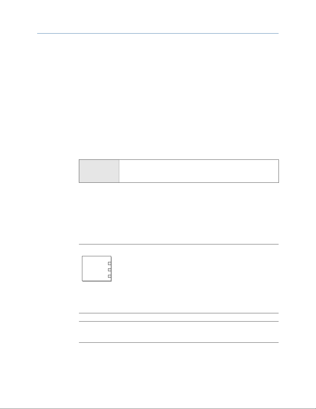
Channel assignment for the function blocksFigure 4-1:
A
A. AO function block or AI function block
B. AI channel or AO channel (CHANNEL)
C. Transducer scale: units index (XD_SCALE)
D. Output scale: units index (OUT_SCALE)
Note
Perform these steps for each AI function block channel (1–4) and the AO function block channel, as
needed.
B
C
D
Configuration and Use Manual 13

Integrate the meter with the network
Procedure
1. Set the (AI or AO) function block channel to the transducer block channel this block
should report.
2. Make sure the transducer scale is set to the correct units, and change it if necessary.
3. Make sure the output scale units matches the transducer scale units, and change it if
necessary.
4.2 Configure AI Linearization
Fieldbus host AI function block > L_TYPE (OD Index 16)
Overview
AI Linearization is used to rescale a process variable. It can also be used to change the
measurement units. The default setting (Direct) is appropriate for most applications.
Procedure
1. Set AI Linearization as desired.
Option Description
Direct The AI block reports process variables directly from the Measurement trans-
ducer block.
Indirect The value from the Measurement transducer block is rescaled as specified by
the Transducer Scale parameters and the Output Scale parameters. The AI
block reports the inverse of the result.
Indirect
Square Root
Important
AI linearization affects only the process variable reported by the AI block. It has no effect on
the Measurement block. Therefore:
• If you set AI Linearization to Indirect or Indirect Square Root, the process variable reported by the
AI block will be different from the process variable read directly from the Measurement
block. Both the display and ProLink III read data directly from the Measurement block.
• Measurement parameters such as Density Damping and Density Cutoff are processed by the
Measurement block, and the result is passed through AI linearization. Using Ai
linearization to implement damping or cutoff processing may not be possible, and is not
recommended.
The value from the Measurement transducer block is rescaled as specified by
the Transducer Scale parameters and the Output Scale parameters. The AI
block reports the square root of the result. This setting is not applicable to
most Micro Motion meters.
2. If you selected Indirect or Indirect Square Root, set the Transducer Scale and Output
Scale parameters:
14 Micro Motion® Fork Density Meters (FDM) with Foundation™ Fieldbus

Integrate the meter with the network
a. Set Transducer Scale: EU at 0% to the value of the process variable when the
transducer block reports 0%.
b. Set Transducer Scale: EU at 100% to the value of the process variable when the
transducer block reports 100%.
c. Set Output Scale: EU at 0% to the value of the process variable when the AI block
reports 0%.
d. Set Output Scale: EU at 100% to the value of the process variable when the AI block
reports 100%.
Specify the two transducer scale parameters in the measurement unit configured
for the transducer block. Specify the two output scale parameters in the
measurement unit configured for the AI block. In most cases, the transducer block
and the AI block use the same measurement unit.
Example: Using scaling to change the measurement unit
The transducer block is configured to measure density in g/cm³. You want the AI block to
report density in oz/in³.
Your lowest expected density value is 0.5 g/cm³. This is equivalent to 0.289 oz/in³.
Your highest expected density value is 0.85 g/cm³. This is equivalent to 0.491 oz/in³.
Set parameters as follows:
• AI Linearization = Indirect
• Transducer Scale: EU at 0% = 0.5
• Transducer Scale: EU at 100% = 0.85
• Output Scale: EU at 0% = 0.289
• Output Scale: EU at 100% = 0.491
Result: As line density varies between 0.5 g/cm³ and 0.85 g/cm³:
• The transducer block varies between 0% and 100%.
• The Measurement block converts this value to a value between 0.5 g/cm³ and
0.85 g/cm³. The result is reported on the display and set to the AI block.
• The AI block applies AI linearization, and reports a value between 0.289 oz/in³ and
0.85 oz/in³.
Configuration and Use Manual 15

Integrate the meter with the network
4.3 Configure process alert limits for the AI blocks
Fieldbus host AI function block > HI_HI_LIM (OD Index 26)
AI function block > HI_HI_PRI (OD Index 25)
AI function block > HI_LIM (OD Index 28)
AI function block > HI_PRI (OD Index 27)
AI function block > LO_LIM (OD Index 30)
AI function block > LO_PRI (OD Index 29)
AI function block > LO_LO_LIM (OD Index 32)
AI function block > LO_LO_PRI (OD Index 31)
AI function block > ALARM_HYS (OD Index 24)
Overview
Process alerts are used to indicate that a process variable is outside the specified limits.
Each AI block has four alert limits: High-High, High, Low, and Low-Low. In general, the
range between High and Low represents the normal process range.
Process alerts are reported only by the affected AI block. They are not shown on the display
or reported by ProLink III.
Prerequisites
Before setting process alert limits, ensure that the four AI blocks are configured for the
appropriate transducer channel (process variable) and measurement unit.
Procedure
1. Select AI Block 1.
2. Set process alert limits:
a. Set the High-High alert to the value of the process variable that will cause the
transmitter to post a High-High alert for this AI block.
b. Set the High alert to the value of the process variable that will cause the
transmitter to post a High alert for this AI block.
c. Set the Low alert to the value of the process variable that will cause the
transmitter to post a Low alert for this AI block.
d. Set the Low-Low alert to the value of the process variable that will cause the
transmitter to post a Low-Low alert for this AI block.
3. For each process alert limit, set the alert priority.
The alert priority is a value between 0 and 15. Higher numbers represent higher
priorities. These values are used for fieldbus network management. They do not
affect transmitter operation: The transmitter will post the alert as soon as the
condition is detected.
4. Repeat for all other AI blocks.
5. Set the alert hysteresis.
16 Micro Motion® Fork Density Meters (FDM) with Foundation™ Fieldbus

Integrate the meter with the network
The alert hysteresis defines a range around the alert limit that operates as a
deadband. The range is defined in terms of % of the output scale. Alert hysteresis is
used to suppress repetitive alerts when the process variable is hovering around the
alert limit.
• A higher value suppresses alerts across a wider range.
• A lower value suppresses alerts across a narrower range. Therefore, alerts may be
posted more frequently.
Important
The alert hysteresis applies to all AI blocks and to all process alert limits.
Example:
AI Block 1 is configured to report line density. The High alert is set at 1.0 g/cm³. The
alert hysteresis is set at 5%.
If line density goes above 1.05 g/cm³, the transmitter posts a High alert. The High
alert remains active until density goes below 0.95 g/cm³.
4.4 Configure the timeout for Field Diagnostic alerts
Fieldbus host DiagnosticsTB > Alert Index (OD Index 017)
Diagnostic TB > Alert timeout (OD Index 083)
Overview
Each Field Diagnostic alert has an individual Timeout parameter. If the alert occurs, it is not
sent to the host until the timeout has expired. Additionally, any associated AI blocks do not
go into fault until the timeout has expired. In other words, the process quality for the AI
block is reported as Good until the timeout expires.
Procedure
1. Set the alert index to the alert you want to configure.
2. Set the timeout as desired:
• Default: 0 seconds
• Range: 0 to 300 seconds
Configuration and Use Manual 17

Integrate the meter with the network
18 Micro Motion® Fork Density Meters (FDM) with Foundation™ Fieldbus

Configure process measurement
5 Configure process measurement
Topics covered in this chapter:
• Verify the calibration factors
• Configure line density measurement
• Configure temperature measurement
• Configure the pressure input
• Set up the API referral application
• Set up concentration measurement
5.1 Verify the calibration factors
Display Not available
ProLink III Device Tools > Calibration Data
Fieldbus host Density Viscosity Meter TB > DEN_A1 (OD Index 035)
Density Viscosity Meter TB > DEN_A2 (OD Index 036)
Density Viscosity Meter TB > DEN_A3 (OD Index 037)
Density Viscosity Meter TB > DEN_A4 (OD Index 038)
Density Viscosity Meter TB > DEN_A5 (OD Index 039)
Density Viscosity Meter TB > DEN_A6 (OD Index 040)
Density Viscosity Meter TB > DEN_A7 (OD Index 041)
Density Viscosity Meter TB > DEN_A8 (OD Index 042)
Density Viscosity Meter TB > DEN_A9 (OD Index 043)
Overview
The calibration factors are used to adjust measurement for the unique traits of the sensor.
Your device was calibrated at the factory. However, you should verify that the calibration
factors that are configured in your device match the factory values.
Prerequisites
You will need the factory values for the calibration factors. These are provided in two
locations:
• The calibration certificate shipped with your meter
• The label inside the transmitter's end-cap
Important
If the transmitter is not the original component, do not use the values from the transmitter label.
Configuration and Use Manual 19

Configure process measurement
Procedure
1. View the calibration factors that are stored in the device.
2. Compare them to the factory values.
• If the values match, no action is required.
• If the values do not match, contact Micro Motion customer service.
Related information
Sample calibration certificate
5.1.1 Calibration factors
The original calibration factors are obtained from factory calibration, and are unique to
each device. They are used to adjust measurements for the specific physical properties of
the device.
The calibration certificate contains two sets of factors:
Density calibration
coefficients
Temperature
compensation coefficients
The calibration certificate also provides the results of the Known Density Verification
procedure that was performed at the factory.
For each calibration performed at the factory, the calibration certificate contains the data
used to calculate the calibration coefficients.
Related information
Sample calibration certificate
Define the relationship between density and the response
of your sensor
Adjust density measurement for the effect of temperature
on sensor response
5.2 Configure line density measurement
The density measurement parameters control how density is measured and reported.
• Configure Density Measurement Unit (Section 5.2.1)
• Configure Density Damping (Section 5.2.2)
• Configure Density Cutoff (Section 5.2.3)
• Configure two‐phase flow parameters (Section 5.2.4)
20 Micro Motion® Fork Density Meters (FDM) with Foundation™ Fieldbus

5.2.1 Configure Density Measurement Unit
Display OFF-LINE MAINT > OFF-LINE CONFG > UNITS > DENS
ProLink III Device Tools > Configuration > Process Measurement > Line Density > Density Unit
Fieldbus host Measurement TB > Density Unit (OD Index 017)
Overview
Density Measurement Unit controls the measurement units that will be used in density
calculations and reporting.
Restriction
If the API referral application is enabled, you cannot change the density measurement unit here. The
density measurement unit is controlled by the API table selection.
Note
"Display" refers to the display on the remotely mounted transmitter, not directly mounted to the
meter. If there is a display directly on the meter, it can only view process variables, and it cannot be
used for any other operation.
Configure process measurement
Procedure
Set Density Measurement Unit to the option you want to use.
The default setting for Density Measurement Unit is g/cm3 (grams per cubic centimeter).
Related information
Set up the API referral application
Options for Density Measurement Unit
The transmitter provides a standard set of measurement units for Density Measurement Unit.
Different communications tools may use different labels.
Options for Density Measurement UnitTable 5-1:
Label Code
Unit description
Specific gravity
Grams per cubic centimeter G/CM3 g/cm3 1100
Grams per liter G/L g/l 1105
Grams per milliliter G/mL g/ml 1104
Kilograms per liter KG/L kg/l 1103
Kilograms per cubic meter KG/M3 kg/m3 1097
(1)
Display ProLink III Fieldbus host
SGU SGU 1114
Configuration and Use Manual 21

Configure process measurement
Options for Density Measurement Unit (continued)Table 5-1:
Label Code
Unit description
Pounds per U.S. gallon LB/GAL lbs/Usgal 1108
Pounds per cubic foot LB/CUF lbs/ft3 1107
Pounds per cubic inch LB/CUI lbs/in3 1106
Short ton per cubic yard ST/CUY sT/yd3 1109
Degrees API D API degAPI 1113
Special unit SPECL special 253
(1) Non‐standard calculation. This value represents line density divided by the density of water at 60 °F.
Display ProLink III Fieldbus host
Define a special measurement unit for density
Display Not available
ProLink III Device Tools > Configuration > Process Measurement > Line Density > Special Units
Fieldbus host Density Viscosity Meter TB > Base Unit (OD Index 081)
Density Viscosity Meter TB > Conversion Factor (OD Index 083)
Density Viscosity Meter TB > Label (OD Index 080)
Procedure
1. Specify Density Special Unit Base.
Density Special Unit Base is the existing density unit that the special unit will be based
on.
2. Calculate Density Special Unit Conversion Factor as follows:
a. x base units = y special units
b. Density Special Unit Conversion Factor = x/y
3. Enter Density Special Unit Conversion Factor.
4. Set User-Defined Label to the name you want to use for the density unit.
The special measurement unit is stored in the transmitter. You can configure the
transmitter to use the special measurement unit at any time.
Example: Defining a special measurement unit for density
You want to measure density in ounces per cubic inch.
1. Set Density Special Unit Base to g/cm3.
2. Calculate Density Special Unit Conversion Factor: 1 g/cm3 = 0.578 oz/in3
22 Micro Motion® Fork Density Meters (FDM) with Foundation™ Fieldbus

3. Set Density Special Unit Conversion Factor to 0.578.
4. Set User-Defined Label to oz/in3.
5.2.2 Configure Density Damping
Display Not available
ProLink III Device Tools > Configuration > Process Measurement > Line Density > Density Damping
Fieldbus host Measurement TB > Density_Damping (OD Index 028)
Overview
Density Damping controls the amount of damping that will be applied to the line density
value.
Damping is used to smooth out small, rapid fluctuations in process measurement. Damping
Value specifies the time period (in seconds) over which the transmitter will spread changes
in the process variable. At the end of the interval, the internal value will reflect 63% of the
change in the actual measured value.
Configure process measurement
Tip
Density damping affects all process variables that are calculated from line density.
Procedure
Set Density Damping to the value you want to use.
The default value is 0 seconds. The range is 0 to 60 seconds.
5.2.3 Configure Density Cutoff
Display Not available
ProLink III Device Tools > Configuration > Process Measurement > Line Density > Density Cutoff Low
Fieldbus host Measurement TB > Density_Low_Cutoff (OD Index 034))
Overview
Density Cutoff Low specifies the lowest density value that will be reported as measured. All
density values below this cutoff will be reported as 0.
Procedure
Set Density Cutoff Low to the value you want to use.
The default value is 0.2 g/cm³. The range is 0.0 g/cm³ to 0.5 g/cm³.
Configuration and Use Manual 23

Configure process measurement
5.2.4 Configure two-phase flow parameters
Display Not available
ProLink III Device Tools > Configuration > Process Measurement > Line Density
Fieldbus host Diagnostic TB > Two-Phase Flow Low Limit (OD Index 009)
Diagnostic TB > Two-Phase Flow High Limit (OD Index 010)
Diagnostic TB > Two-Phase Flow Timeout (OD Index 008)
Overview
The two-phase flow parameters control how the transmitter detects and reports twophase flow (gas in a liquid process or liquid in a gas process).
Note
Two-phase flow is sometimes referred to as slug flow.
Procedure
1. Set Two-Phase Flow Low Limit to the lowest density value that is considered normal in
your process.
Values below this will cause the transmitter to post Alert A105 ().
Tip
Gas entrainment can cause your process density to drop temporarily. To reduce the
occurrence of two-phase flow alerts that are not significant to your process, set Two-Phase Flow
Low Limit slightly below your expected lowest process density.
You must enter Two-Phase Flow Low Limit in g/cm³, even if you configured another unit
for density measurement.
2. Set Two-Phase Flow High Limit to the highest density value that is considered normal in
your process.
Values above this will cause the transmitter to post Alert A105 (Two-Phase Flow).
Tip
To reduce the occurrence of two-phase flow alerts that are not significant to your process, set
Two-Phase Flow High Limit slightly above your expected highest process density.
You must enter Two-Phase Flow High Limit in g/cm³, even if you configured another
unit for density measurement.
3. Set Two-Phase Flow Timeout to the number of seconds that the transmitter will wait for
a two-phase flow condition to clear before posting the alert.
24 Micro Motion® Fork Density Meters (FDM) with Foundation™ Fieldbus
Loading...