

Page 1

快速安装指南
MMI-20032808, Rev AB
2016 年 12
月
高准(
Micro Motion®)LNG 系列 科里奥利质量流量计和仪表
Page 2

其他信息
如需了解完整的产品规格,请参阅产品样本。如需获得故障排查信息,请参阅组态手册。各产品样本和各手册都可访问高准网站
www.micromotion.com/documentation 获取。
返修政策
根据高准规定的程序返修设备。遵循这些程序可确保符合政府运输机构的法规要求,同时有助于为高准员工提供安全的工作环境。
如未遵循高准返修程序,高准将不会接受返回的设备。
有关于返修程序和返修表格,请登录 www.micromotion.com 获取,或致电高准客户服务部门获取。
Emerson Flow 客户服务
电子邮件:
• 全球: flow.support@emerson.com
• 亚太地区: APflow.support@emerson.com
电话:
北美和南美 欧洲和中东 亚太地区
美国
加拿大
墨西哥
阿根廷
巴西
委内瑞拉
800-522-6277
+1 303-527-5200
+41 (0) 41 7686 111
+54 11 4837 7000
+55 15 3413 8000
+58 26 1731 3446
英国
荷兰
法国
德国
意大利
中欧和东欧
俄罗斯/独联体 +7 495 981 9811
埃及
阿曼
卡塔尔
科威特
南非
沙特阿拉伯
阿联酋
0870 240 1978
+31 (0) 704 136 666
0800 917 901
0800 182 5347
8008 77334
+41 (0) 41 7686 111
0800 000 0015
800 70101
431 0044
663 299 01
800 991 390
800 844 9564
800 0444 0684
澳大利亚
新西兰
印度
巴基斯坦
中国
日本
韩国
新加坡
泰国
马来西亚
800 158 727
099 128 804
800 440 1468
888 550 2682
+86 21 2892 9000
+81 3 5769 6803
+82 2 3438 4600
+65 6 777 8211
001 800 441 6426
800 814 008
Page 3

目录
目录
第 1 章 安装准备 ................................................................................................................................1
1.1 部件标识 .............................................................................................................................................. 1
1.2 安装检查表 ...........................................................................................................................................1
1.3 电源要求 .............................................................................................................................................. 2
第 2 章 安装方式 ................................................................................................................................4
2.1 安装传感器 ...........................................................................................................................................4
2.2 安装双核处理器(选项 1) ..................................................................................................................4
2.3 安装带 MVD Direct Connect 本安型安全栅的增强型核心处理器(选项 2) ........................................5
第 3 章 接线 .......................................................................................................................................8
3.1 将核心处理器连接到传感器 ................................................................................................................. 8
3.2 双核处理器接线(选项 1) ................................................................................................................14
3.3 增强型核心处理器接线(选项 2) .....................................................................................................16
第 4 章 接地 .....................................................................................................................................19
4.1 双核处理器接地 ................................................................................................................................. 19
4.2 增强型核心处理器接地 ...................................................................................................................... 20
第 5 章 基础组态 ..............................................................................................................................21
5.1 通电 ................................................................................................................................................... 21
5.2 传感器启动检查表 ..............................................................................................................................21
5.3 规格 ................................................................................................................................................... 22
快速安装指南 i
Page 4

目录
ii 高准 LNG 系列科里奥利质量流量计
Page 5
1 安装准备
本章所涉及的主题:
部件标识
•
安装检查表
•
电源要求
•
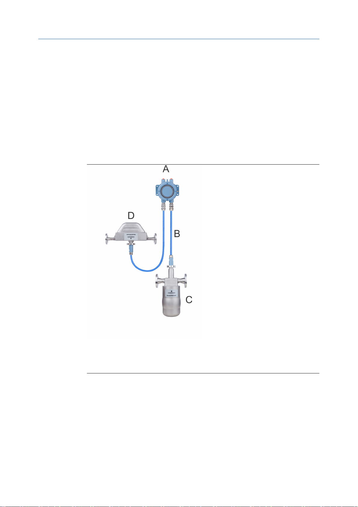
1.1 部件标识
安装准备
双核处理器
A.
B. 9 线电缆
C. 适用于灌装测量应用的 LNGM10 型仪表
D. 适用于回流测量应用的 LNGS06 型仪表
1.2
快速安装指南 1
安装检查表
确保认证标签上规定的危险区域适合于 LNG 仪表的安装环境。
□
检查当前环境和过程温度,确保其在仪表的限制范围内。
□
确保核心处理器使用的是低压直流电源。过高的电压可能会损坏核心处理器。
□
有关本安型应用,请参阅 Micro Motion ATEX、UL 或 CSA 安装说明。
□
只要导线管的开口不是朝上,您就可以在任何方向安装 LNG 电子元件。
□
Page 6

安装准备
注意!
若导线管开口朝上,冷凝液可能进入外壳,进而可能损坏内部的电子元件。
安装传感器时,要保证外壳上的流向箭头与过程介质的实际流向一致。(流向也可使
□
用软件进行选择。)
LNGS06
气体回流传感器
1.3 电源要求
• 18 至 30 V 直流,3 W(典型),5 W(最大)
• 最小 28 VDC,随附长度为 300 米的 1 mm2 电源线
• 启动时,电源在电气部件电源输入端最低电压为 18 V 的条件下必须提供至少 0.5 A
的短暂电流。
• 最大稳态电流为 0.2A
• 安装(过电压)类别为 II 类,污染等级为 2 级
LNGM10
灌装传感器
注
电源要求假设每根电缆仅向单台核心处理器供电。
•
• 必须选择适宜的电源线长度和导体线径,以便在电源端子获得 0.2 A 的负载电流及至少 18 V
直流电压。
电缆选型公式
M = 18V + (R x L x 0.2A)
• M:最低电源电压
• R:电缆电阻
• L:电缆长度
68 °F (20 °C)
线规 电阻
14 AWG 0.0050 欧/英尺
16 AWG 0.0080 欧/英尺
下的典型电源线电阻表 1-1:
2 高准 LNG 系列科里奥利质量流量计
Page 7

68 °F (20 °C) 下的典型电源线电阻 (续)表 1-1:
线规 电阻
18 AWG 0.0128 欧/英尺
20 AWG 0.0204 欧/英尺
2.5 平方毫米 0.0136 欧/米
1.5 平方毫米 0.0228 欧/米
1.0 平方毫米 0.0340 欧/米
0.75 平方毫米 0.0460 欧/米
0.50 平方毫米 0.0680 欧/米
安装准备
快速安装指南 3
Page 8
安装方式
2 安装方式
本章所涉及的主题:
安装传感器
•
• 安装双核处理器(选项 1)
• 安装带 MVD Direct Connect 本安型安全栅的增强型核心处理器(选项 2)
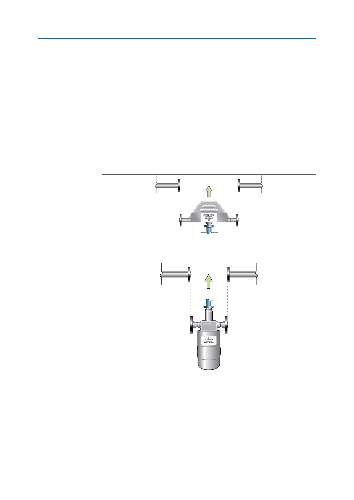
2.1 安装传感器
1. 安装 LNGS06。
2.2
2. 安装 LNGM10。
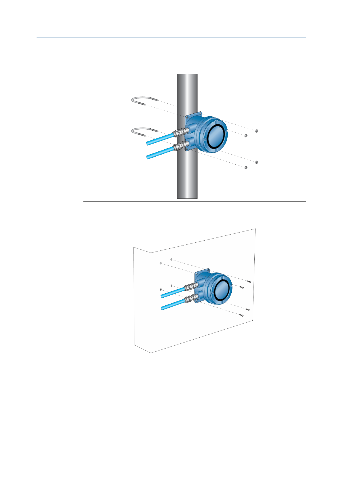
安装双核处理器(选项 1)
将双核处理器安装在管道或墙壁上。
4 高准 LNG 系列科里奥利质量流量计
Page 9
安装方式
图 2-1:
图 2-2:
双核处理器:管道安装型
双核处理器:墙壁安装型
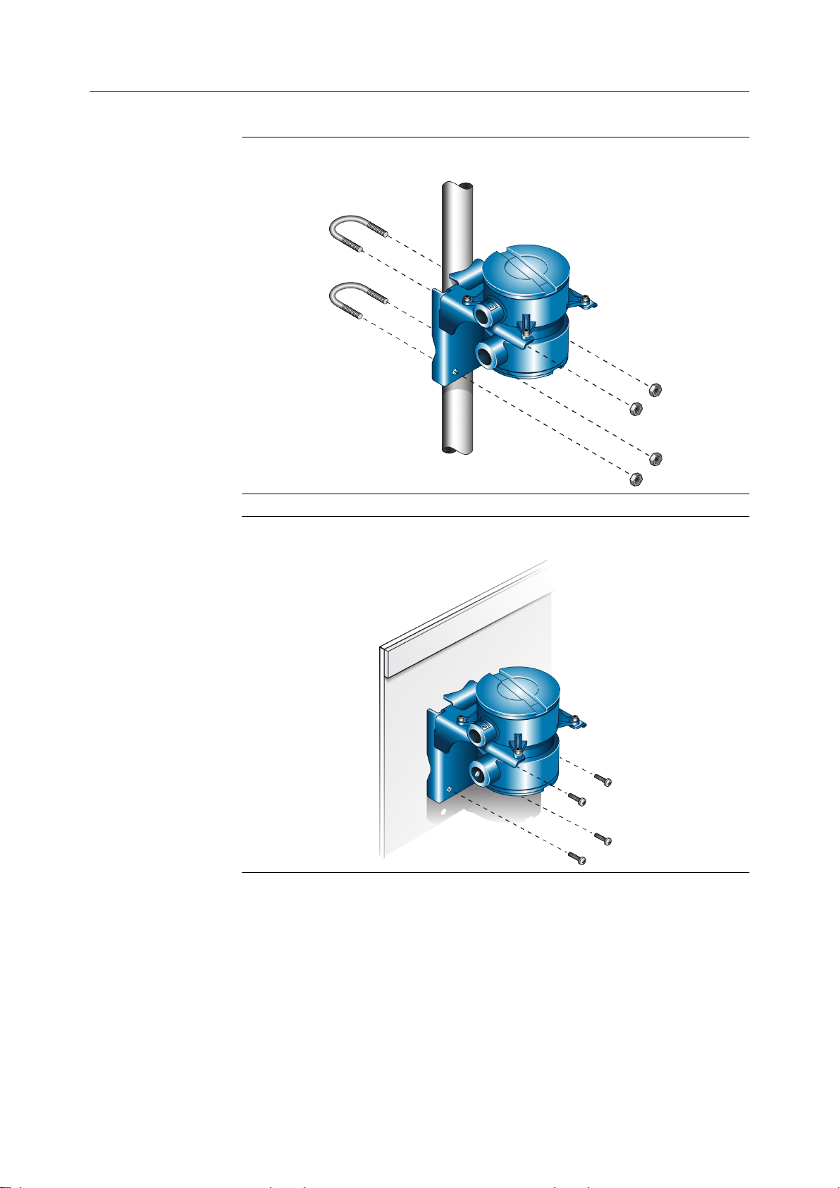
2.3 安装带 MVD Direct Connect 本安型安全栅的增
强型核心处理器(选项 2)
将增强型核心处理器安装在管道或墙壁上。
1.
快速安装指南 5
Page 10
安装方式
图 2-3:
图 2-4:
增强型核心处理器:管道安装型
增强型核心处理器:墙壁安装型
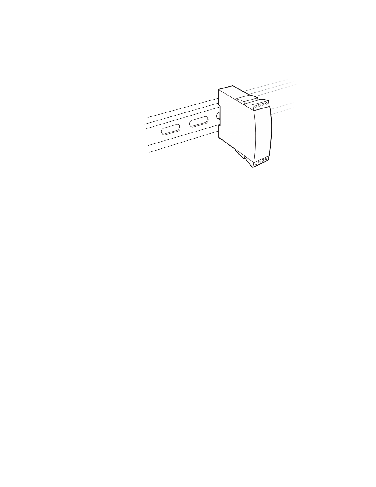
2. 将安全栅安装在 DIN 导轨上。
6 高准 LNG 系列科里奥利质量流量计
Page 11

安装方式
DIN 导轨上的安全栅安装图 2-5:
快速安装指南 7
Page 12

接线
3 接线
本章所涉及的主题:
将核心处理器连接到传感器
•
• 双核处理器接线(选项 1)
• 增强型核心处理器接线(选项 2)
3.1 将核心处理器连接到传感器
3.1.1 使用护套电缆连接核心处理器与传感器
先决条件
对于危险区域的安装,请将护套电缆安装在用户自备的密封金属导线管中,该导线管为封
闭的电缆提供 360°端子屏蔽。
注意!
传感器接线是本安型。为保持传感器接线是本安型,请使传感器接线独立于电源接线和输出
•
接线。
使电缆远离诸如变压器、电机和电源线等设备,这些设备都会产生大磁场。电缆、电缆密封
•
接头或导管安装不当,可能会导致测量不精确或流量计故障。
外壳密封不当可能会使电子部件受潮,进而可能导致测量误差或流量计故障的产生。将滴水
•
管安装在导管和电缆上(如有必要)。检查并润滑所有密封垫圈和 O 型圈。完全关闭并拧紧
所有外壳盖和导线管开口。
步骤
将电缆穿过导线管。
1.
在核心处理器处,将各接线的裸端按颜色插入核心处理器末端相应的端子。不得露
2.
出任何裸线。请参见下表。
表 3-1:
导线颜色 功能
黑色 屏蔽线
棕色
红色
橙色
黄色 温度回升
绿色
蓝色
紫色
灰色
核心处理器端子标识
驱动 +
驱动 –
温度 –
左检测 +
右检测 +
温度 +
右检测 –
8 高准 LNG 系列科里奥利质量流量计
Page 13
接线
表 3-1:
导线颜色 功能
白色
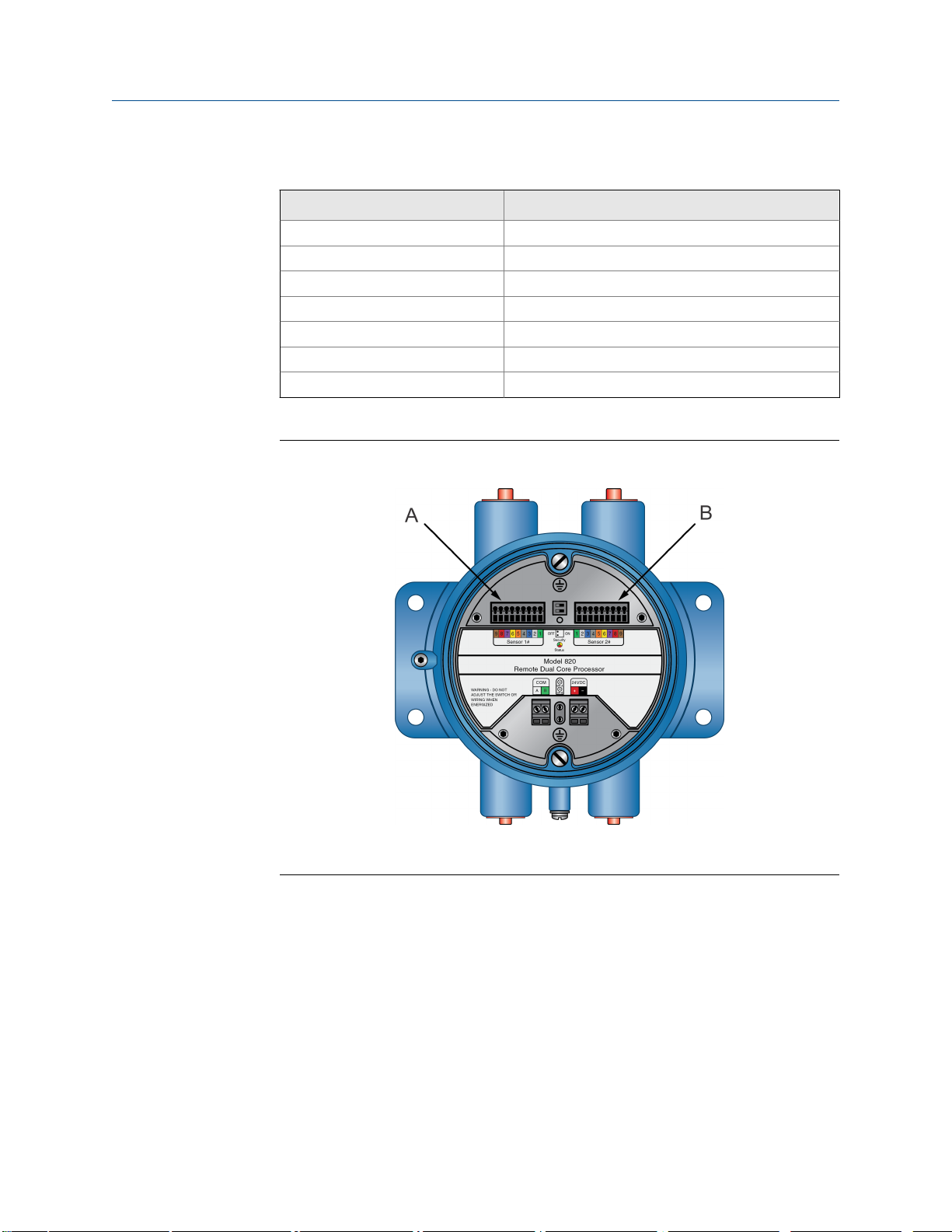
图 3-1:
核心处理器端子标识 (续)
左检测 –
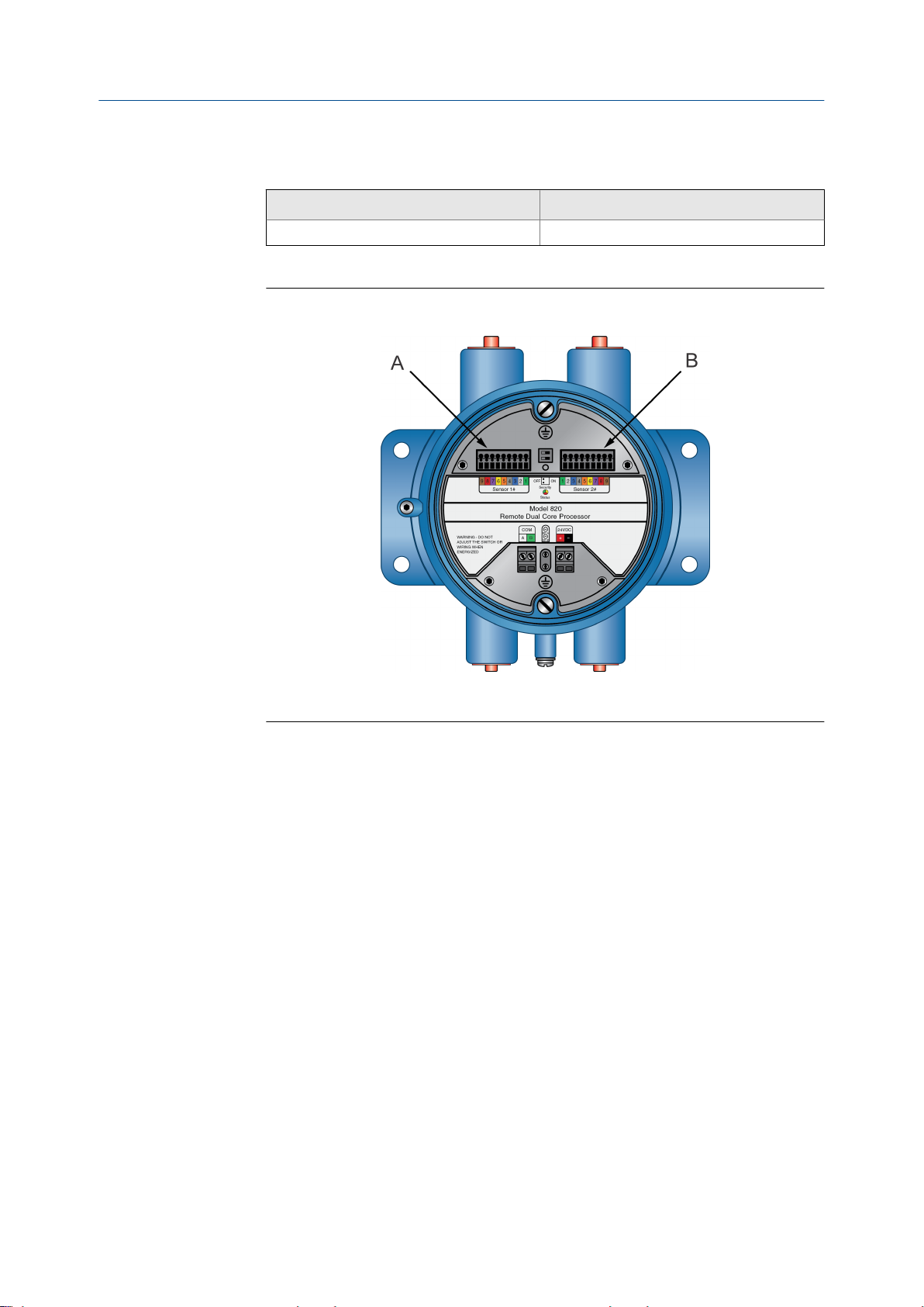
双核处理器端子
A. 传感器 1
B. 传感器 2
快速安装指南 9
Page 14

A
B
I
H
G
F
E
D
C
J
接线
图 3-2:
A.
B.
C.
D.
E.
F.
G.
H.
I.
J.
增强型核心处理器端子
棕色
紫色
黄色
橙色
灰色
蓝色
白色
绿色
红色
接地螺钉(黑色)
3.1.2
使用屏蔽电缆连接核心处理器与传感器
先决条件
对于危险区域的安装,核心处理器末端处的屏蔽电缆安装必须配合使用电缆接头。您可以
从高准购买符合危险区域使用要求的电缆接头。也可以使用其他供应商的电缆接头。
注意!
传感器接线是本安型。为保持传感器接线是本安型,请使传感器接线独立于电源接线和输出
•
接线。
使电缆远离诸如变压器、电机和电源线等设备,这些设备都会产生大磁场。电缆、电缆密封
•
接头或导管安装不当,可能会导致测量不精确或流量计故障。
外壳密封不当可能会使电子部件受潮,进而可能导致测量误差或流量计故障的产生。将滴水
•
管安装在导管和电缆上(如有必要)。检查并润滑所有密封垫圈和 O 型圈。完全关闭并拧紧
所有外壳盖和导线管开口。
步骤
识别电缆接头组件和电缆。
1.
10 高准 LNG 系列科里奥利质量流量计
Page 15
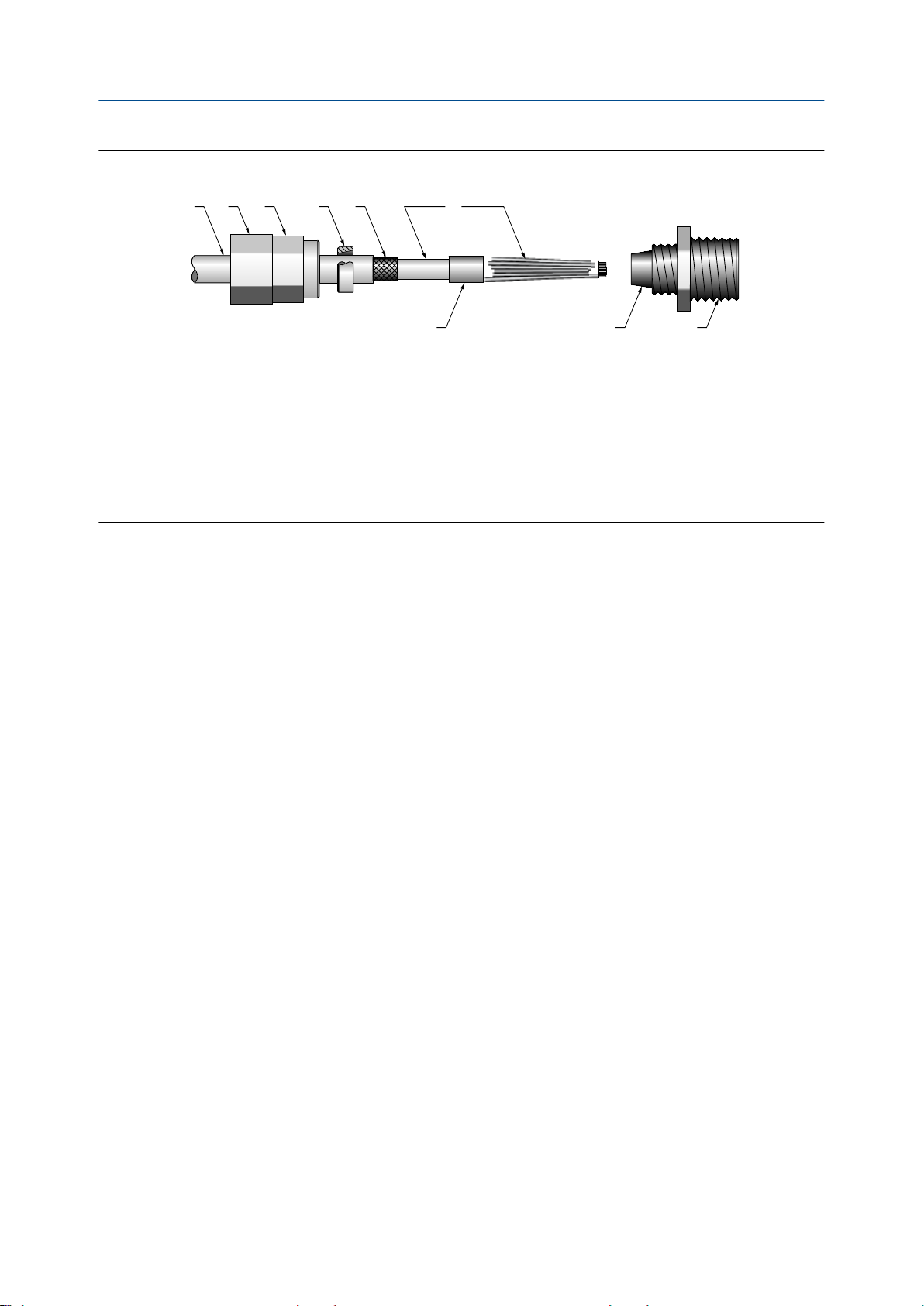
电缆接头和电缆(分解图)图 3-3:
A B C D E F
G H I
电缆
A.
密封螺母
B.
压紧螺母
C.
黄铜压缩环
D.
编织屏蔽层
E.
电缆
F.
胶带或热缩管
G.
卡座(图示为螺纹接头的组成部分)
H.
螺纹接头
I.
接线
拧松压紧螺母中的螺纹接头。
2.
3. 将螺纹接头拧到 9 线制电缆的导线管开口上。用手拧紧它后再转一圈。
将压缩环、压紧螺母和密封螺母滑到电缆上。确保压缩环正确定向,以便锥形部分
4.
与螺纹接头的锥形端正确接合。
将电缆末端穿过螺纹接头,使编织屏蔽层滑到螺纹接头的锥形端上。
5.
将压缩环滑到编织屏蔽层上。
6.
将压紧螺母拧到螺纹接头上。用手拧紧密封螺母和压紧螺母,确保压缩环可以固定
7.
编织屏蔽层。
8. 使用 25 毫米(1 英寸)扳手拧紧密封螺母和压紧螺母,扭矩为 20–25 英尺磅
(27–34 牛顿-米)。参见图 3-4, 了解一个完整的电缆接头装配图示。
快速安装指南 11
Page 16

A
B
C
E
D
F
G A
接线
图 3-4:
A.
B.
C.
D.
E.
F.
G.
拆下核心处理器盖。
9.
在核心处理器处,根据以下程序连接电缆:
10.
组装的电缆接头和电缆的横截面
电缆
密封螺母
密封件
压紧螺母
编织屏蔽层
黄铜压缩环
螺纹接头
将各接线的裸端按颜色插入核心处理器末端相应的端子。不得露出任何裸线。
a.
请参见下表。
表 3-2:
导线颜色 功能
黑色 屏蔽线
棕色
红色
橙色
黄色 温度回升
绿色
蓝色
紫色
灰色
白色
核心处理器端子标识
驱动 +
驱动 –
温度 –
左检测 +
右检测 +
温度 +
右检测 –
左检测 –
12 高准 LNG 系列科里奥利质量流量计
Page 17
A
B
I
H
G
F
E
D
C
J
接线
图 3-5:
双核处理器端子
A. 传感器 1
B. 传感器 2
图 3-6:
A.
B.
C.
D.
E.
F.
G.
H.
I.
J.
增强型核心处理器端子
棕色
紫色
黄色
橙色
灰色
蓝色
白色
绿色
红色
接地螺钉(黑色)
快速安装指南 13
拧紧螺钉,以将接线固定到位。
b.
c. 请确保垫圈完好,并为所有 O 型圈涂抹润滑脂,然后装回核心处理器外壳盖并
根据需要拧紧所有螺钉。
Page 18

接线
3.2 双核处理器接线(选项 1)
根据本节说明来安装双核处理器。
3.2.1 在双核处理器上连接 9 线电缆
先决条件
根据高准 LNG 系列科里奥利质量流量计安装指南中的说明来准备和安装电缆。
步骤
拆下双核处理器外壳盖。
1.
将各条线的裸端插入接线端子中。确保没有任何线缆暴露在外。
2.
3. 按照匹配的颜色接线(参见表 3-1)。
A. 传感器 1
B. 传感器 2
4. 如果线长不是 3 米,则使用 ProLink III 来寄存不同的长度。有关更多信息,请参阅
高准® (Micro Motion®) LNG 系列科里奥利质量流量计和密度仪表组态和使用手册。
3.2.2
14 高准 LNG 系列科里奥利质量流量计
双核处理器电源接线
先决条件
根据高准 LNG 系列科里奥利质量流量计安装指南中的说明来准备和安装电缆。
步骤
将电源线连接至正极 (+) 端子和负极 (-) 端子。
将正极线连接到红色正极 (+) 端子,将负极线连接到黑色负极 (-) 端子。
Page 19

A.
接线
电源
3.2.3 双核处理器输出接线
先决条件
根据高准 LNG 系列科里奥利质量流量计安装指南中的说明来准备和安装电缆。
步骤
将 RS-485 线连接至白色 RS485A 和绿色 RS485B 接口。
A. RS-485
服务端口
B.
快速安装指南 15
Page 20

接线
3.3 增强型核心处理器接线(选项 2)
根据本节说明来安装增强型核心处理器。
3.3.1 在增强型核心处理器上连接 9 线电缆
先决条件
根据高准 LNG 系列科里奥利质量流量计安装指南中的说明来准备和安装电缆。
步骤
将各条线的裸端插入接线端子中。确保没有任何线缆暴露在外。
1.
2. 按照匹配的颜色接线(参加表 3-1)。
拧紧螺钉,以将接线固定到位。
3.
确保垫圈完好,然后紧紧关闭并密封所有外壳盖。
4.
3.3.2 MVD Direct Connect 本安型安全栅接线
先决条件
根据高准 LNG 系列科里奥利质量流量计安装指南中的说明来准备和安装电缆。
步骤
将增强型核心处理器连接到安全栅:
a. 将 RS-485 线从增强型核心处理器连接到安全栅上的本安型 RS-485 端子(端子 43 和
44),匹配 A 和 B。请参见下表和下图。
b. 将电源线从核心处理器连接到安全栅上的本安型 VDC 端子(端子 42 和 41)之间的电
源线,匹配正极和负极(+ 和 –)。切勿端接安全栅的屏蔽线。请参见下表和下图。
表 3-3:
功能 核心处理器端子 安全栅本安端子
RS-485 A 3 43
RS-485 B 4 44
VDC + 1 42
VDC – 2 41
c. 将 RS-485 线连接到安全栅上的非本安型 RS-485 端子(端子 13 和 14)。这些线将在下
一步中用于将安全栅连接到远程主机。切勿端接安全栅的屏蔽线。
d. 将电源线连接到安全栅上的非本安型 VDC 端子(端子 11 和 12)。这些线将在下一步
中用于将安全栅连接到电源。
增强型核心处理器和安全栅本安型端子
16 高准 LNG 系列科里奥利质量流量计
Page 21

接线
图 3-7:
A.
B.
安全栅端子
用于连接至增强型核心处理器的本安型端子
用于连接至远程主机和电源的非本安型端子
3.3.3 将电源连接到 MVD Direct Connect 本安型安全栅
• 只要每个装置都能获得足够的电能,您可以将多个 MVD Direct Connect 装置连接到
单个电源。
本安型安全栅的电源同时也可以用于对其他设备供电。
•
3.3.4
步骤
从安全栅连接电源线,匹配正极和负极(+ 和 –)。
图 3-8:
A.
B.
安全栅端子
用于连接至增强型核心处理器的本安型端子
用于连接至远程主机和电源的非本安型端子
将远程主机连接到 MVD Direct Connect 本安型安全栅
1. 将 RS-485 线从安全栅连接到远程主机的 RS-485 端子。
快速安装指南 17
Page 22

接线
图 3-9:
A.
B.
远程主机上屏蔽线端接。
2.
安全栅端子
用于连接至增强型核心处理器的本安型端子
用于连接至远程主机和电源的非本安型端子
切勿增加外部电阻。安全栅包含内部上拉/下拉电阻和端接电阻。
18 高准 LNG 系列科里奥利质量流量计
Page 23

4 接地
本章所涉及的主题:
双核处理器接地
•
增强型核心处理器接地
•
仪表必须按照现场适用的标准进行接地。客户有责任了解并遵守所有适用标准。
高准建议根据以下指导进行接地操作:
• 使用铜线,2.0 mm2 或更大线径。
• 所有接地导线应尽可能短,阻抗小于 1 欧姆。
将接地导线直接接地,或者按照工厂标准操作。
•
4.1 双核处理器接地
接地
如需安装双核处理器,请遵循本程序。
注
将处理器接地,或者遵照设备的接地网络要求。接地不当可能导致测量误差。
步骤
如果管道中的接头未接地,则将接地线连接到双核处理器上的内部或外部接地螺钉。
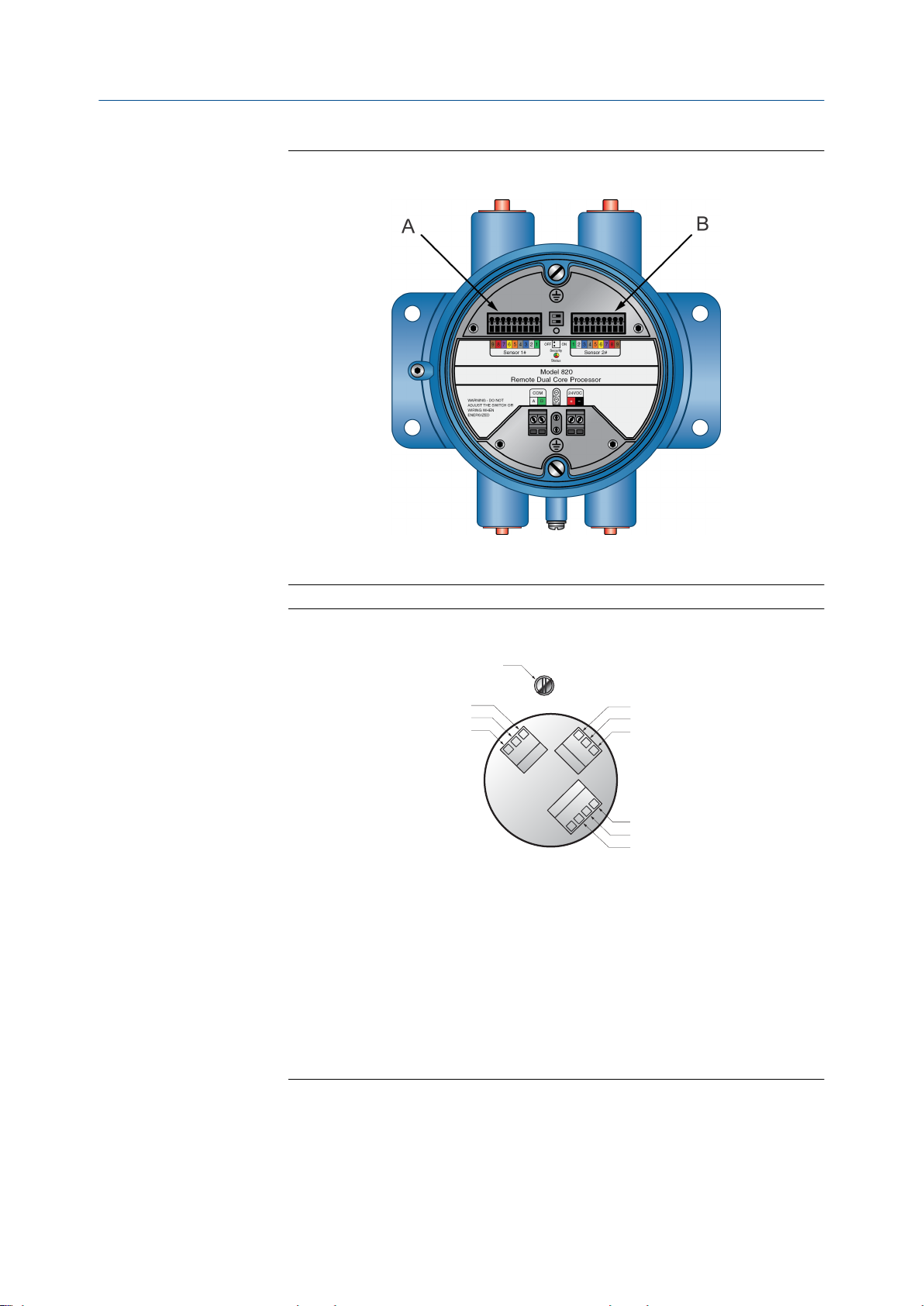
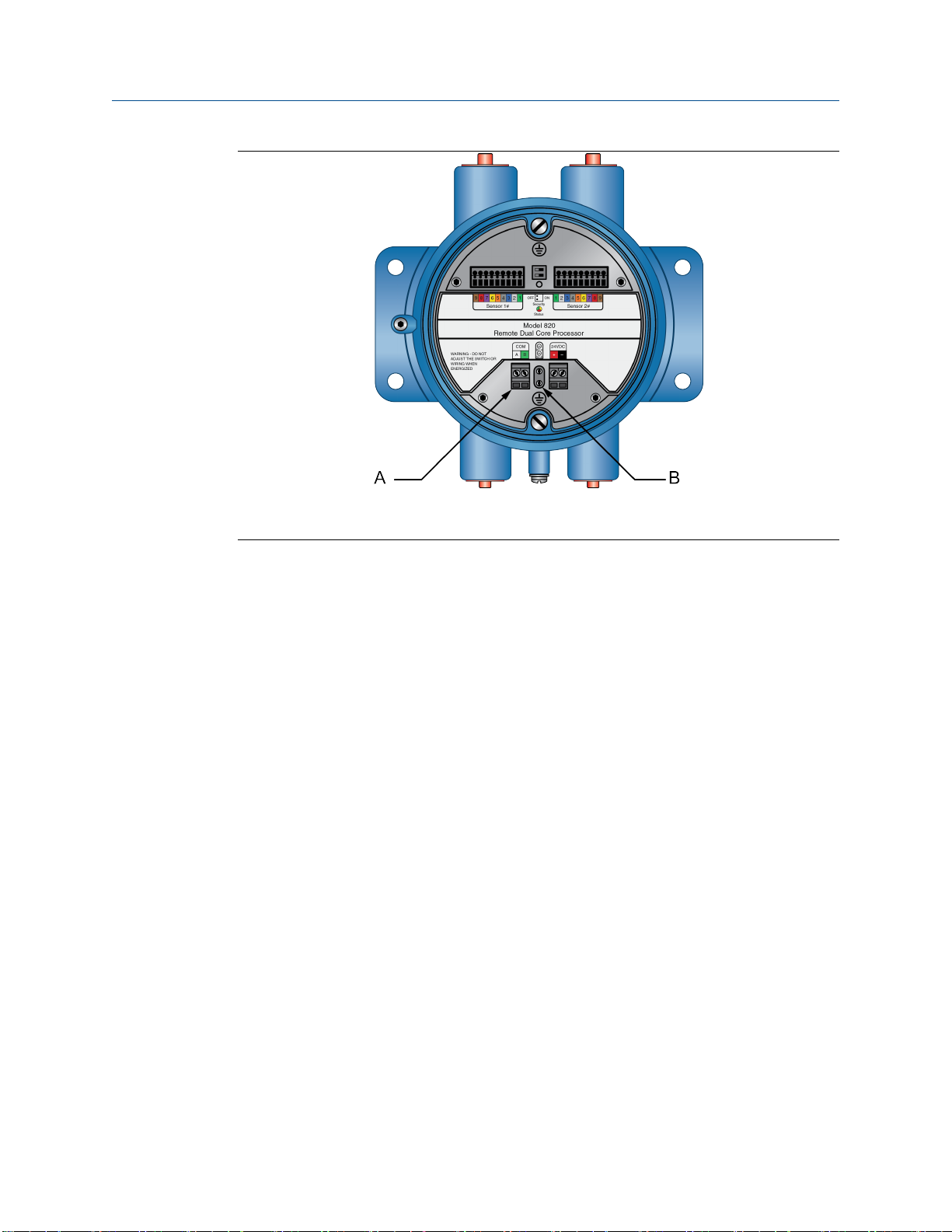
图 4-1:
双核处理器接地螺钉
内部接地螺钉
A.
外部接地螺钉
B.
快速安装指南 19
Page 24

接地
4.2 增强型核心处理器接地
如需安装增强型核心处理器,请遵循本程序。
注
将处理器接地,或者遵照设备的接地网络要求。接地不当可能导致测量误差。
步骤
如果管道中的接头未接地,则将接地线连接到增强型核心处理器上的内部或外部接地螺
钉。
图 4-2:
内部接地螺钉
A.
外部接地螺钉
B.
内部接地螺钉
C.
增强型核心处理器接地螺钉
20 高准 LNG 系列科里奥利质量流量计
Page 25

5 基础组态
本章所涉及的主题:
通电
•
传感器启动检查表
•
规格
•
5.1 通电
给流量计通电之前,请关闭并拧紧所有外壳盖。
1.
警告!
在盖子尚未安装到位的情况下运行传感器会产生触电危险,进而导致死亡、伤害或财产损失。
确保用于现场接线的安全栅隔离和保护盖、以及电路板所在腔体、电子元件模块及外壳在处
理器通电之前全都安装到位。
基础组态
5.2
警告!
若在危险区域使用服务端口进行通讯,则可能引起爆炸。在危险区域使用服务端口与核心处
理器通讯之前,确保周围气体中不含有爆炸性气体。
打开供电电源。传感器将自动执行诊断例程。传感器通电程序结束后,核心处理器
2.
将在贸易交接安全模式下工作,不会产生报警。
注
随后,传感器即可在通电大约一分钟(这个时间因具体型号而异)之后开始接收过程介质。
但电子元件要预热到平衡状态,则需要大约十分钟。在这十分钟内,处理器可能稍微有点不
稳定或不准确。
传感器启动检查表
安装检查表
将法兰和垫圈牢固地安装在仪表两侧
□
对仪表上下游的管道进行支撑
□
流向箭头与过程流向一致
□
上下游阀门正确打开或关闭
□
电缆连接点已密封且连接牢固
□
电源接线检查表
正极端子 (+) 和负极端子 (-)
□
接地端子
□
DC
□
电源
□
快速安装指南 21
Page 26

基础组态
18 至 30 VDC
□
5.3 规格
物理特性
传感器外壳
电子元件外壳 聚氨酯涂层铝质
接液材料
LNGS06 重量 4.6 kg
LNGM10 重量 7.9 kg
电缆密封接头入口
304L 不锈钢
316L 不锈钢
含 EN1092-1 PN40 F316/316L 对焊法兰
入口:两个 3/4″ NPT 导管母口用于供 9 线制接
线连接至 LNG 传感器
出口:两个 1/2”— 14 NPT 或 M20 X 1.5 导管母
口用于输出和电源
电气
输出连接 非本安型:
一对接线端子用于 RS-485 信号线连接(双核处
理器,对于带 MVD Direct Connect 本安型安全
栅的增强型核心处理器)
电源连接
数字通讯
一对接线端子接收 24V DC 电源(双核处理器,
对于带 MVD Direct Connect 本安型安全栅的增
强型核心处理器)
Modbus / RS-485 支持 4800、9600、19200 和
38400 波特的数据传输率(双核处理器,对于带
MVD Direct Connect 本安型安全栅的增强型核
心处理器)
输出信号
测量变量
质量流量
•
温度
•
精度和流量
精度和流量
批量精度
LNGS06 LNGM10
批量的 ±1.0% 批量的 ±0.5%
22 高准 LNG 系列科里奥利质量流量计
Page 27

基础组态
精度和流量
温度精度
液体的最大流量
注
如要确定仪表性能,典型的批量测量/配送流量如下:
• 批处理时间不少于 3 分钟。
• LNGM10 流量不低于 20 kg/min,LNGS06 流量不低于 2 kg/min。
流体为液氮或液化天然气。
•
LNGS06 LNGM10
±1.0℃ 加/减(±) 读数的 0.5%
(过程温度范围:–100℃至
60℃)
±1.0℃ 加/减(±) 读数的 1.0%
(过程温度范围:-196℃
至-100℃)
1800 kg/hr 18000 kg/hr
±1.0℃ 加/减(±) 读数的 0.5%
(过程温度范围:–100℃至
60℃)
±1.0℃ 加/减(±) 读数的 1.0%
(过程温度范围:-196℃
至-100℃)
快速安装指南 23
Page 28

*MMI-20032808*
MMI-20032808
Rev AB
2016
艾默生过程控制有限公司
上海市浦东新区新金桥路
邮编:201206
电话:86-21-2892 9000
传真:86-21-2892 9001
服务热线: 400-820-1996(免费)
广州办事处
广州市东风中路 410-412 号
时代地产中心 2107 室
邮编:510030
电话:86-20-2883 8900
传真:86-20-2883 8901
成都办事处
成都市科华北路 62 号
力宝大厦 S-10-10 室
邮编:610041
电话:86-28-6235 0188
传真:86-28-6235 0199
西安办事处
西安市高新区锦业一路 34 号
西安软件园研发大厦 9 层
邮编:710065
电话:86-29-8865 0888
传真:86-29-8865 0899
1277 号
艾默生过程控制流量技术有限公司
江苏南京江宁区兴民南路 111 号
邮编: 211100
电话: 86-25-5117 7888
传真: 86-25-5117 7999
北京办事处
北京市朝阳区雅宝路 10 号
凯威大厦 13 层
邮编: 100020
电话: 86-10-5821 1188
传真: 86-10-5821 11 00
乌鲁木齐办事处
乌鲁木齐市五一路 160 号
鸿福大饭店 C 座 1001 室
邮编:830000
电话:86-991-580 2277
传真:86-991-580 3377
深圳办事处
深圳市南山区海德三道
天利中央商务广场 B 座 1803
邮编: 518054
电话:86-755-8659 5099
传真:86-755-8659 5095
©
2016
Micro Motion, Inc. 保留所有权利
Micro Motion 和 Emerson 标志是艾默生电气公司的注册商标和服
务商标。
以及 PlantWeb 均为艾默生过程管理子公司的标志。所有其他商标
均为它们各自所有者的资产。
Micro Motion、ELITE、MVD、ProLink、MVD Direct Connect
Page 29
Quick Start Guide
MMI-20032808, Rev AB
December 2016
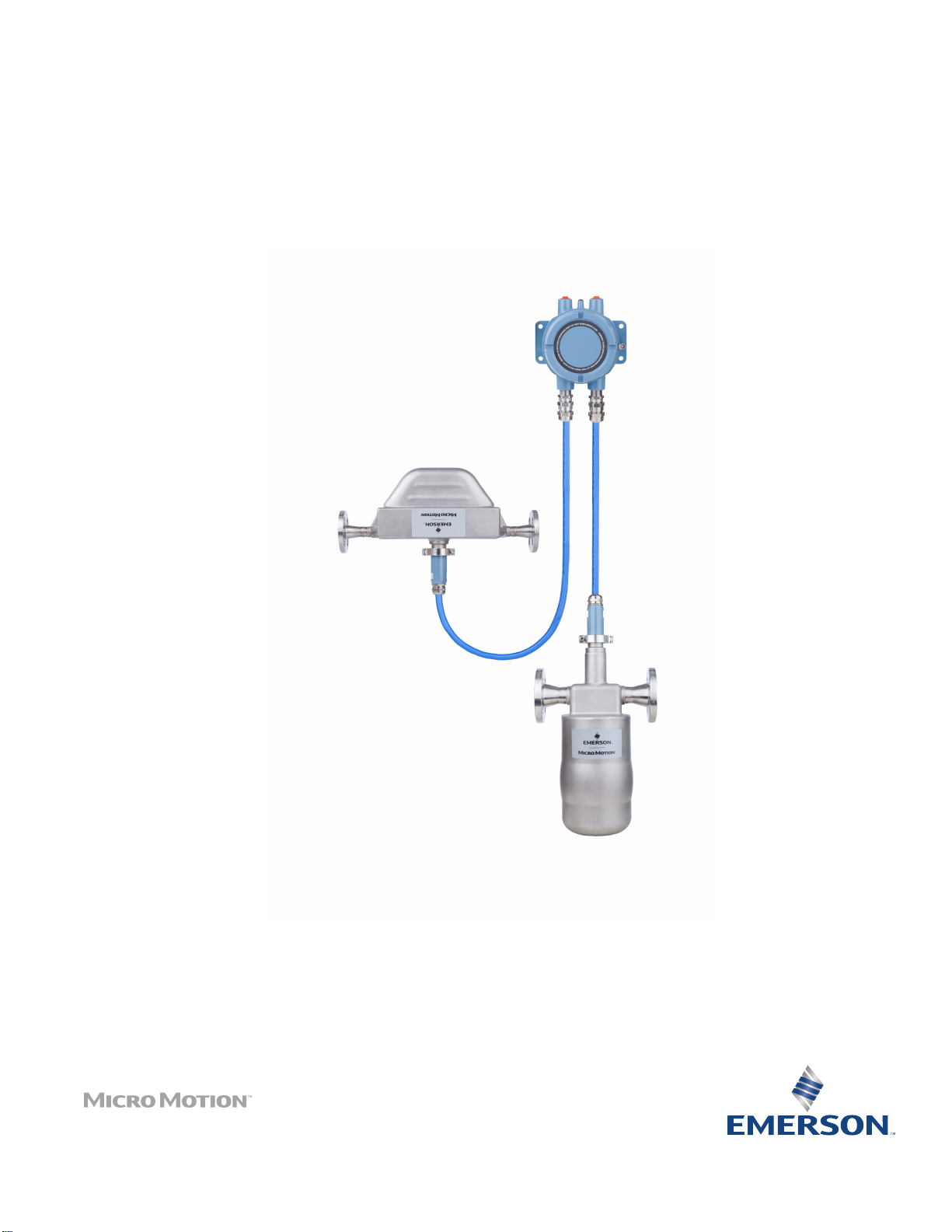
Micro Motion® Liquified Natural Gas Meter
Page 30

Other information
Full product specifications can be found in the product data sheet. Troubleshooting information can be found in the configuration
manual. Product data sheets and manuals are available from the Micro Motion web site at www.micromotion.com/documentation.
Return policy
Follow Micro Motion procedures when returning equipment. These procedures ensure legal compliance with government
transportation agencies and help provide a safe working environment for Micro Motion employees. Micro Motion will not accept
your returned equipment if you fail to follow Micro Motion procedures.
Return procedures and forms are available on our web support site at www.micromotion.com, or by phoning the Micro Motion
Customer Service department.
Emerson Flow customer service
Email:
• Worldwide: flow.support@emerson.com
• Asia-Pacific: APflow.support@emerson.com
Telephone:
North and South America Europe and Middle East Asia Pacific
United States 800-522-6277 U.K. 0870 240 1978 Australia 800 158 727
Canada +1 303-527-5200 The Netherlands +31 (0) 704 136 666 New Zealand 099 128 804
Mexico +41 (0) 41 7686 111 France 0800 917 901 India 800 440 1468
Argentina +54 11 4837 7000 Germany 0800 182 5347 Pakistan 888 550 2682
Brazil +55 15 3413 8000 Italy 8008 77334 China +86 21 2892 9000
Venezuela +58 26 1731 3446 Central & Eastern +41 (0) 41 7686 111 Japan +81 3 5769 6803
Russia/CIS +7 495 981 9811 South Korea +82 2 3438 4600
Egypt 0800 000 0015 Singapore +65 6 777 8211
Oman 800 70101 Thailand 001 800 441 6426
Qatar 431 0044 Malaysia 800 814 008
Kuwait 663 299 01
South Africa 800 991 390
Saudi Arabia 800 844 9564
UAE 800 0444 0684
Page 31

Contents
Contents
Chapter 1 Planning ...........................................................................................................................1
1.1 Component identification .............................................................................................................. 1
1.2 Installation checklist .......................................................................................................................1
1.3 Power requirements .......................................................................................................................2
Chapter 2 Mounting ......................................................................................................................... 4
2.1 Mount the sensors ..........................................................................................................................4
2.2 Mount the dual core processor (option 1) .......................................................................................4
2.3 Mount the enhanced core processor with MVD Direct Connect I.S. Barrier (option 2) .....................5
Chapter 3 Wiring ............................................................................................................................. 8
3.1 Wire the core processor to the sensor ............................................................................................ 8
3.2 Wire the dual core processor (option 1) ........................................................................................14
3.3 Wire the enhanced core processor (option 2) ...............................................................................16
Chapter 4 Grounding ......................................................................................................................20
4.1 Ground a dual core processor .......................................................................................................20
4.2 Ground the enhanced core processor ...........................................................................................21
Chapter 5 Basic configuration ........................................................................................................ 23
5.1 Power on ......................................................................................................................................23
5.2 Sensor start up checklist ...............................................................................................................23
5.3 Specifications ...............................................................................................................................24
Quick Start Guide i
Page 32

Contents
ii Micro Motion Liquified Natural Gas Meter
Page 33

1 Planning
Topics covered in this chapter:
Component identification
•
Installation checklist
•
Power requirements
•
1.1 Component identification
Planning
A. Dual core processor
B. 9-wire cable
C. Model LNGM10 for filling measurement
D. Model LNGS06 for returning measurement
1.2
Quick Start Guide 1
Installation checklist
□
Make sure that the hazardous area specified on the approval tag is suitable for the
environment in which the LNG meters will be installed.
Page 34

Planning
□
Verify that the local ambient and process temperatures are within the limits of the
LNG meters.
□
Verify that you are using low-voltage DC power for the core processor. Excess
voltage can damage the core processor.
□
For I.S. applications, refer to Micro Motion ATEX, UL, or CSA installation instructions.
□
Mount the LNG electronics in any orientation as long as the conduit openings do not
point upward.
CAUTION!
Upward-facing conduit openings risk condensation entering the housing that can
damage the electronics.
□
Install the sensors so that the flow direction arrow on the case matches the actual
forward flow of the process. (Flow direction is also software-selectable.)
LNGS06
Gas return sensor
LNGM10
Filling sensor
1.3 Power requirements
•
18 to 30 VDC, 3 watts typical, 5 watts maximum
• Minimum 28 VDC with 300 meters of 1 mm2 power-supply cable
• At startup, power source must provide a minimum of 0.5 amperes of short term
current at a minimum of 18 volts at the electrical parts power input terminals
• The maximum steady state current is 0.2A
• Complies with Installation (Overvoltage) Category II, Pollution Degree 2
Note
• Power requirements assume a single core processor per cable.
• Length and conductor diameter of the power cable must be sized to provide 18 VDC
minimum at the power terminals, at a load current of 0.2 amps.
2 Micro Motion Liquified Natural Gas Meter
Page 35

Cable sizing formula
M = 18V + (R x L x 0.2A)
• M: minimum supply voltage
• R: cable resistance
• L: cable length
Typical power cable resistance at 68 °F (20 °C)Table 1-1:
Wire gauge Resistance
14 AWG 0.0050 Ω/ft
16 AWG 0.0080 Ω/ft
18 AWG 0.0128 Ω/ft
20 AWG 0.0204 Ω/ft
2.5 mm
1.5 mm
1.0 mm
0.75 mm
0.50 mm
2
2
2
2
2
0.0136 Ω/m
0.0228 Ω/m
0.0340 Ω/m
0.0460 Ω/m
0.0680 Ω/m
Planning
Quick Start Guide 3
Page 36

Mounting
2 Mounting
Topics covered in this chapter:
Mount the sensors
•
Mount the dual core processor (option 1)
•
Mount the enhanced core processor with MVD Direct Connect I.S. Barrier
•
(option 2)
2.1 Mount the sensors
1. Mount the LNGS06.
2.2
2. Mount the LNGM10.
Mount the dual core processor (option 1)
Mount the dual core processor on either a pipe or a wall.
4 Micro Motion Liquified Natural Gas Meter
Page 37

Mounting
Dual core processor: pipe mountFigure 2-1:
Dual core processor: wall mountFigure 2-2:
2.3 Mount the enhanced core processor with MVD
Direct Connect I.S. Barrier (option 2)
1. Mount the enhanced core processor on either a pipe or a wall.
Quick Start Guide 5
Page 38

Mounting
Enhanced core processor: pipe mountFigure 2-3:
Enhanced core processor: wall mountFigure 2-4:
2. Mount the barrier on a DIN rail.
6 Micro Motion Liquified Natural Gas Meter
Page 39
Mounting
Barrier mount on DIN railFigure 2-5:
Quick Start Guide 7
Page 40

Wiring
3 Wiring
Topics covered in this chapter:
Wire the core processor to the sensor
•
Wire the dual core processor (option 1)
•
Wire the enhanced core processor (option 2)
•
3.1 Wire the core processor to the sensor
3.1.1 Wire the core processor to the sensor using jacketed
cable
Prerequisites
For hazardous area installations, install the jacketed cable inside a user-supplied sealed
metallic conduit that provides 360° termination shielding for the enclosed cable.
CAUTION!
• Sensor wiring is intrinsically safe. To keep sensor wiring intrinsically safe, keep the
sensor wiring separated from power supply wiring and output wiring.
• Keep cable away from devices such as transformers, motors, and power lines, which
produce large magnetic fields. Improper installation of cable, cable gland, or conduit
could cause inaccurate measurements or flow meter failure.
• Improperly-sealed housings can expose electronics to moisture, which can cause
measurement error or flowmeter failure. Install drip legs in conduit and cable, if
necessary. Inspect and grease all gaskets and O-rings. Fully close and tighten all housing
covers and conduit openings.
Procedure
1. Run the cable through the conduit.
2. At the core processor, insert the stripped end of each wire into the corresponding
terminal at the core processor ends, matching by color. No bare wires should remain
exposed. See the following table.
Core processor terminal designationsTable 3-1:
Wire color Function
Black Drain wires
Brown Drive +
Red Drive –
8 Micro Motion Liquified Natural Gas Meter
Page 41
Core processor terminal designations (continued)Table 3-1:
Wire color Function
Orange Temperature –
Yellow Temperature return
Green Left pickoff +
Blue Right pickoff +
Violet Temperature +
Gray Right pickoff –
White Left pickoff –
Dual core processor terminalsFigure 3-1:
Wiring
A. Sensor 1
B. Sensor 2
Quick Start Guide 9
Page 42

A
B
I
H
G
F
E
D
C
J
Wiring
Enhanced core processor terminalsFigure 3-2:
A. Brown
B. Violet
C. Yellow
D. Orange
E. Gray
F. Blue
G. White
H. Green
I. Red
J. Ground screw (black)
3.1.2
Wire the core processor to the sensor using shielded
cable
Prerequisites
For hazardous area installations, shielded cable must be installed with cable glands at the
core processor end. Cable glands that meet hazardous area requirements can be
purchased from Micro Motion. Cable glands from other vendors can be used.
CAUTION!
• Sensor wiring is intrinsically safe. To keep sensor wiring intrinsically safe, keep the
sensor wiring separated from power supply wiring and output wiring.
• Keep cable away from devices such as transformers, motors, and power lines, which
produce large magnetic fields. Improper installation of cable, cable gland, or conduit
could cause inaccurate measurements or flow meter failure.
• Improperly-sealed housings can expose electronics to moisture, which can cause
measurement error or flowmeter failure. Install drip legs in conduit and cable, if
necessary. Inspect and grease all gaskets and O-rings. Fully close and tighten all housing
covers and conduit openings.
Procedure
1. Identify the components of the cable gland and cable.
10 Micro Motion Liquified Natural Gas Meter
Page 43
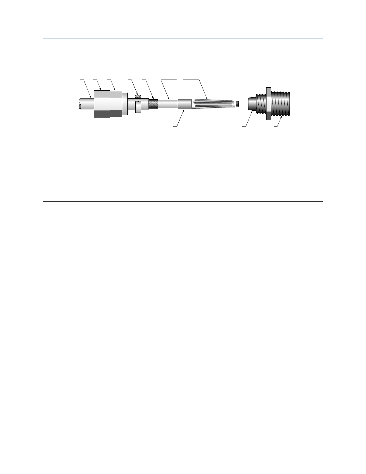
Cable gland and cable (exploded view)Figure 3-3:
A B C D E F
G H I
A. Cable
B. Sealing nut
C. Compression nut
D. Brass compression ring
E. Braided shield
F. Cable
G. Tape or heat-shrink tubing
H. Clamp seat (shown as integral to nipple)
I. Nipple
Wiring
2. Unscrew the nipple from the compression nut.
3. Screw the nipple into the conduit opening for the 9-wire cable. Tighten it to one turn
past hand-tight.
4. Slide the compression ring, compression nut, and sealing nut onto the cable. Make
sure the compression ring is oriented so the taper will mate properly with the
tapered end of the nipple.
5. Pass the cable end through the nipple so the braided shield slides over the tapered
end of the nipple.
6. Slide the compression ring over the braided shield.
7. Screw the compression nut onto the nipple. Tighten the sealing nut and
compression nut by hand to ensure that the compression ring traps the braided
shield.
8. Use a 25-mm (1-inch) wrench to tighten the sealing nut and compression nut to
20–25 foot-pounds (27–34 N-m) of torque.
Quick Start Guide 11
Page 44

A
B
C
E
D
F
G A
Wiring
Cross-section of assembled cable gland with cableFigure 3-4:
A. Cable
B. Sealing nut
C. Seal
D. Compression nut
E. Braided shield
F. Brass compression ring
G. Nipple
9. Remove the core processor cover.
10. At the core processor, connect the cable according to the following procedure:
a. Insert the stripped end of each wire into the corresponding terminal at the core
processor ends, matching by color. No bare wires should remain exposed. See
the following table.
Core processor terminal designationsTable 3-2:
Wire color Function
Black Drain wires
Brown Drive +
Red Drive –
Orange Temperature –
Yellow Temperature return
Green Left pickoff +
Blue Right pickoff +
Violet Temperature +
Gray Right pickoff –
White Left pickoff –
12 Micro Motion Liquified Natural Gas Meter
Page 45

A
B
I
H
G
F
E
D
C
J
Wiring
Dual core processor terminalsFigure 3-5:
A. Sensor 1
B. Sensor 2
Enhanced core processor terminalsFigure 3-6:
A. Brown
B. Violet
C. Yellow
D. Orange
E. Gray
F. Blue
G. White
H. Green
I. Red
J. Ground screw (black)
Quick Start Guide 13
Page 46

Wiring
b. Tighten the screws to hold the wires in place.
c. Ensure integrity of gaskets, grease all O-rings, then replace the core processor
housing cover and tighten all screws, as required.
3.2 Wire the dual core processor (option 1)
Use this section for a dual core processor installation.
3.2.1 Connect the 9-wire cable on a dual core processor
Prerequisites
Prepare and install the cable according to the instructions in the Micro Motion Liquified
Natural Gas Meter Installation Guide.
Procedure
1. Remove the dual processor housing cover.
2. Insert the stripped ends of the individual wires into the terminal blocks. Ensure that
no bare wires remain exposed.
3. Match the wires color for color.
A. Sensor 1
B. Sensor 2
4. If the wire length is not 3m, use ProLink III to register a different length. For more
information, see the Micro Motion LNG Series Meters Configuration and Use Manual.
14 Micro Motion Liquified Natural Gas Meter
Page 47

3.2.2 Wire the dual core processor power supply
Prerequisites
Prepare and install the cable according to the instructions in the Micro Motion Liquified
Natural Gas Meter Installation Guide.
Procedure
Connect the power supply wires to the positive (+) and negative (–) terminals.
Terminate the positive (line) wire on the positive (+) red terminal and the return (neutral)
wire on the negative (–) black terminal.
Wiring
A. Power supply
3.2.3
Quick Start Guide 15
Wire the dual core processor outputs
Prerequisites
Prepare and install the cable according to the instructions in the Micro Motion Liquified
Natural Gas Meter Installation Guide.
Procedure
Connect the RS-485 wires to the white RS485A and green RS485B connectors.
Page 48
Wiring
A. RS-485
B. Service port
3.3 Wire the enhanced core processor (option 2)
Use this section for an enhanced core processor installation.
3.3.1
3.3.2
Connect the 9-wire cable on an enhanced core processor
Prerequisites
Prepare and install the cable according to the instructions in the Micro Motion Liquified
Natural Gas Meter Installation Guide.
Procedure
1. Insert the stripped ends of the individual wires into the terminal blocks. Ensure that
no bare wires remain exposed.
2. Match the wires color for color.
3. Tighten the screws to hold the wires in place.
4. Ensure integrity of gaskets, then tightly close and seal all housing covers.
Wire the MVD Direct Connect I.S. barrier
Prerequisites
Prepare and install the cable according to the instructions in the Micro Motion Liquified
Natural Gas Meter Installation Guide.
16 Micro Motion Liquified Natural Gas Meter
Page 49

Wiring
Procedure
Connect the enhanced core processor to the barrier:
a. Connect the RS-485 wires from the enhanced core processor to the I.S. RS-485
terminals at the barrier (terminals 43 and 44), matching A and B. See the following
table and figure.
b. Connect the power supply wires from the core processor to the I.S. VDC terminals at
the barrier (terminals 42 and 41), matching positive and negative (+ and –). Do not
terminate the shields at the barrier. See the following table and figure.
Enhanced core processor and barrier I.S. terminalsTable 3-3:
Function Core processor terminals Barrier I.S. terminals
RS-485 A 3 43
RS-485 B 4 44
VDC + 1 42
VDC – 2 41
c. Connect the RS-485 wires to the non-I.S. RS-485 terminals at the barrier (terminals 13
and 14). These wires will be used in the next step to connect the barrier to the remote
host. Do not terminate the shields at the barrier.
d. Connect the power supply wires to the non-I.S. VDC terminals at the barrier (terminals
11 and 12). These wires will be used in the next step to connect the barrier to the power
supply.
Barrier terminalsFigure 3-7:
A. I. S. terminals for connection to enhanced core processor
B. Non I.S. terminals for connection to remote host and power supply
Quick Start Guide 17
Page 50

Wiring
3.3.3 Wire the power supply to the MVD Direct Connect I.S.
barrier
• You can connect multiple MVD Direct Connect installations to a single power
supply, as long as each installation receives sufficient power.
• For power supply to I.S. barrier connections, the power supply can be used to power
other equipment.
Procedure
Connect the power supply wires from the barrier, matching positive and negative (+
and –).
Barrier terminalsFigure 3-8:
3.3.4
A. I.S. terminals for connection to enhanced core processor
B. Non I.S. terminals for connection to remote host and power supply
Wire the remote host to the MVD Direct Connect I.S.
Barrier
1. Connect the RS-485 wire from the barrier to the RS-485 terminals at the remote
host.
18 Micro Motion Liquified Natural Gas Meter
Page 51

Barrier terminalsFigure 3-9:
A. I.S. terminals for connection to enhanced core processor
B. Non I.S. terminals for connection to remote host and power supply
2. Terminate the shields at the remote host.
Do not add external resistors. The barrier contains internal pull-up/pull-down and
termination resistors.
Wiring
Quick Start Guide 19
Page 52

Grounding
4 Grounding
Topics covered in this chapter:
Ground a dual core processor
•
Ground the enhanced core processor
•
The meter must be grounded according to the standards that are applicable at the site.
The customer is responsible for knowing and complying with all applicable standards.
Micro Motion suggests the following guides for grounding practices:
• Use copper wire, 2,0 mm2 or larger wire size.
• Keep all ground leads as short as possible, less than 1 Ω impedance.
• Connect ground leads directly to earth, or follow plant standards.
4.1 Ground a dual core processor
Use this procedure if your installation contains a dual core processor.
Note
Ground the processor to earth, or follow ground network requirements for the facility. Improper
grounding can cause measurement error.
Procedure
If the joints in the pipeline are not grounded, connect a ground wire to the internal or
external grounding screw located on the dual core processor.
20 Micro Motion Liquified Natural Gas Meter
Page 53

Grounding
Dual core processor grounding screwsFigure 4-1:
4.2
A. Internal grounding screws
B. External grounding screw
Ground the enhanced core processor
Use this procedure if your installation contains an enhanced core processor.
Note
Ground the processor to earth, or follow ground network requirements for the facility. Improper
grounding can cause measurement error.
Procedure
If the joints in the pipeline are not grounded, connect a ground wire to the internal or
external grounding screw located on the enhanced core processor.
Quick Start Guide 21
Page 54

Grounding
Enhanced core processor grounding screwsFigure 4-2:
A. Internal ground screw
B. External ground screw
C. Internal ground screw
22 Micro Motion Liquified Natural Gas Meter
Page 55

5 Basic configuration
Topics covered in this chapter:
Power on
•
Sensor start up checklist
•
Specifications
•
5.1 Power on
1. Before you apply power to the sensors, close and tighten all housing covers.
WARNING!
Operating the sensor without covers in place creates electrical hazards that can cause
death, injury, or property damage. Make sure safety barrier partition and covers for the
field-wiring, circuit board compartments, electronics module, and housing are all in
place before applying power to the processor.
Basic configuration
5.2
WARNING!
Using the service port to communicate in a hazardous area can cause an explosion.
Before using the service port to communicate with the core processor in a hazardous
area, make sure the atmosphere is free from explosive gases.
2. Turn on the electrical power at the power supply. The sensors will automatically
perform diagnostic routines. When the sensors have completed their power-up
sequence, the core processor should work in custody transfer secure mode without
alarms.
Note
The sensor is ready to receive process fluid approximately one minute after power-up (time
varies with models). However, approximately ten minutes are required for the electronics to
warm up to equilibrium. During this ten-minute period, the processor may exhibit minor
instability or inaccuracy.
Sensor start up checklist
Mounting checklist
□
Flange and gasket are securely installed on both sides of meter
□
Piping is supported upstream and downstream of the meter
□
Flow arrow same as the process flow direction
□
Upstream and downstream valves correctly opened or closed
Quick Start Guide 23
Page 56

Basic configuration
□
Cable connection is sealed and secure
Power wiring checklist
□
Terminals positive (+) and negative (–)
□
Ground terminal
□
DC
□
Power
□
18 to 30 VDC
5.3 Specifications
Physical
Sensor housing 304L stainless steel
Electronics housing Polyurethane-painted aluminum
Wetted materials 316L stainless steel
LNGS06 weight 4.6 kg
LNGM10 weight 7.9 kg
Cable gland entrances Inlets: Two 3/4” NPT female conduit ports for 9-
With EN1092-1 PN40 F316/316L weld neck
flanges
wire connection to LNG sensors
Outlets: Two 1/2” — 14 NPT or M20 x 1.5 female
conduit ports for outputs and power supply
Electrical
Output connections
Power connections One pair of wiring terminals accepts 24V DC
Digital communications Modbus / RS-485 accepts data rates 4800,
24 Micro Motion Liquified Natural Gas Meter
Not intrinsically safe type:
One pair of wiring terminals for RS-485 signal
cable connection for dual core processor and
enhanced core processor with MVD Direct Connect I.S. barrier
power for dual core processor and enhanced
core processor with MVD Direct Connect I.S.
barrier
9600, 19200, and 38400 baud for dual core processor and enhanced core processor with MVD
Direct Connect I.S. barrier
Page 57

Output signals
Measurement variables • Mass flow
• Temperature
Accuracy and flow rate
Accuracy and flow rate LNGS06 LNGM10
Batch accuracy ±1.0% of batch ±0.5% of batch
Temperature accuracy ±1.0 °C ±0.5% of reading (proc-
ess temperature: -100 to 60 °C)
±1.0 °C ±1.0% of reading (process temperature: -196 to
-100 °C)
Maximum flow rates for liquids 1800 kg/hr 18000 kg/hr
±1.0 °C ±0.5% of reading (process temperature: -100 to 60 °C)
±1.0 °C ±1.0% of reading (process temperature: -196 to
-100 °C)
Basic configuration
Note
For determining the performance capabilities of our meters, the typical batch/dispensing flow rates
are defined as follows:
• Batch time is no less than 3 minutes.
• The LNGM10 flow rate is no less than 20 kg/min and the LNGS06 flow rate is no less than 2 kg/
min.
• Fluid is liquid nitrogen or LNG.
Quick Start Guide 25
Page 58

Micro Motion Inc. USA
Worldwide Headquarters
7070 Winchester Circle
Boulder, Colorado 80301
T +1 303-527-5200
T +1 800-522-6277
F +1 303-530-8459
www.micromotion.com
Micro Motion Europe
Emerson Automation Solutions
Neonstraat 1
6718 WX Ede
The Netherlands
T +31 (0) 70 413 6666
F +31 (0) 318 495 556
www.micromotion.nl
*MMI-20032808*
MMI-20032808
Rev AB
2016
Micro Motion Asia
Emerson Automation Solutions
1 Pandan Crescent
Singapore 128461
Republic of Singapore
T +65 6777-8211
F +65 6770-8003
Micro Motion United Kingdom
Emerson Automation Solutions
Emerson Process Management Limited
Horsfield Way
Bredbury Industrial Estate
Stockport SK6 2SU U.K.
T +44 0870 240 1978
F +44 0800 966 181
Micro Motion Japan
Emerson Automation Solutions
1-2-5, Higashi Shinagawa
Shinagawa-ku
Tokyo 140-0002 Japan
T +81 3 5769-6803
F +81 3 5769-6844
©
2016 Micro Motion, Inc. All rights reserved.
The Emerson logo is a trademark and service mark of Emerson
Electric Co. Micro Motion, ELITE, ProLink, MVD and MVD Direct
Connect marks are marks of one of the Emerson Automation
Solutions family of companies. All other marks are property of their
respective owners.
 Loading...