

Page 1

Instruction Manual
P/N 20002373, Rev. B
May 2008
Micro Motion
®
LF-Series Transmitters
Configuration and Use Manual
• Field-mount transmitter with 1 mA/1 FO flow-only
• Field-mount transmitter with 1 mA/1 FO multivariable
• Field-mount transmitter with 2 mA/1 FO multivariable
• DIN rail mount transmitter with 1 mA/1 FO flow-only
• DIN rail mount transmitter with 2 mA/ 1FO multivariable
Page 2

Page 3

Contents
Chapter 1 Before You Begin . . . . . . . . . . . . . . . . . . . . . . . . . . . . . . . . . . . . . 1
1.1 Overview . . . . . . . . . . . . . . . . . . . . . . . . . . . . . . . . . . . . . . . . . . . . . . . . . . . . . . . . . . . 1
1.2 Safety . . . . . . . . . . . . . . . . . . . . . . . . . . . . . . . . . . . . . . . . . . . . . . . . . . . . . . . . . . . . . 1
1.3 Transmitter codes used in this manual . . . . . . . . . . . . . . . . . . . . . . . . . . . . . . . . . . . . 1
1.4 Determining your transmitter type and version . . . . . . . . . . . . . . . . . . . . . . . . . . . . . . 2
1.4.1 Transmitter type and outputs option board. . . . . . . . . . . . . . . . . . . . . . . . . 2
1.4.2 Version . . . . . . . . . . . . . . . . . . . . . . . . . . . . . . . . . . . . . . . . . . . . . . . . . . . . 2
1.5 Flowmeter documentation . . . . . . . . . . . . . . . . . . . . . . . . . . . . . . . . . . . . . . . . . . . . . . 3
1.6 Using this manual . . . . . . . . . . . . . . . . . . . . . . . . . . . . . . . . . . . . . . . . . . . . . . . . . . . . 3
1.6.1 Communication tools . . . . . . . . . . . . . . . . . . . . . . . . . . . . . . . . . . . . . . . . . 3
1.7 Planning the configuration. . . . . . . . . . . . . . . . . . . . . . . . . . . . . . . . . . . . . . . . . . . . . . 4
1.8 Pre-configuration worksheet . . . . . . . . . . . . . . . . . . . . . . . . . . . . . . . . . . . . . . . . . . . . 4
1.9 Customer service . . . . . . . . . . . . . . . . . . . . . . . . . . . . . . . . . . . . . . . . . . . . . . . . . . . . 5
Chapter 2 Using the Transmitter Display . . . . . . . . . . . . . . . . . . . . . . . . . . . . 7
2.1 Overview . . . . . . . . . . . . . . . . . . . . . . . . . . . . . . . . . . . . . . . . . . . . . . . . . . . . . . . . . . . 7
2.2 Components . . . . . . . . . . . . . . . . . . . . . . . . . . . . . . . . . . . . . . . . . . . . . . . . . . . . . . . . 7
2.3 Using the optical switches . . . . . . . . . . . . . . . . . . . . . . . . . . . . . . . . . . . . . . . . . . . . . . 8
2.4 Using the display . . . . . . . . . . . . . . . . . . . . . . . . . . . . . . . . . . . . . . . . . . . . . . . . . . . . . 8
2.4.1 Display menus . . . . . . . . . . . . . . . . . . . . . . . . . . . . . . . . . . . . . . . . . . . . . . 8
2.4.2 Display password. . . . . . . . . . . . . . . . . . . . . . . . . . . . . . . . . . . . . . . . . . . . 8
2.4.3 Entering milliamp and frequency range values with the display. . . . . . . . . 9
Chapter 3 Connecting with ProLink II Software . . . . . . . . . . . . . . . . . . . . . . . 11
3.1 Overview . . . . . . . . . . . . . . . . . . . . . . . . . . . . . . . . . . . . . . . . . . . . . . . . . . . . . . . . . . 11
3.2 Requirements . . . . . . . . . . . . . . . . . . . . . . . . . . . . . . . . . . . . . . . . . . . . . . . . . . . . . . 11
3.3 ProLink II configuration upload/download . . . . . . . . . . . . . . . . . . . . . . . . . . . . . . . . . 12
3.4 Connecting from a PC to an LF-Series field-mount transmitter . . . . . . . . . . . . . . . . 12
3.4.1 Connecting to the service port . . . . . . . . . . . . . . . . . . . . . . . . . . . . . . . . . 12
3.4.2 Connecting to the RS-485 terminals or an RS-485 network . . . . . . . . . . 14
3.4.3 Connecting to the primary mA terminals or to a
HART multidrop network . . . . . . . . . . . . . . . . . . . . . . . . . . . . . . . . . . . . . 16
3.5 Connecting from a PC to an LF-Series DIN rail mount transmitter . . . . . . . . . . . . . . 17
3.5.1 Connecting to the RS-485 terminals or an RS-485 network . . . . . . . . . . 17
3.5.2 HART/Bell202 connections . . . . . . . . . . . . . . . . . . . . . . . . . . . . . . . . . . . 19
Chapter 4 Connecting with the 375 Field Communicator. . . . . . . . . . . . . . . . . 21
4.1 Overview . . . . . . . . . . . . . . . . . . . . . . . . . . . . . . . . . . . . . . . . . . . . . . . . . . . . . . . . . . 21
4.2 Communicator device descriptions . . . . . . . . . . . . . . . . . . . . . . . . . . . . . . . . . . . . . . 21
4.3 Connecting to a transmitter . . . . . . . . . . . . . . . . . . . . . . . . . . . . . . . . . . . . . . . . . . . . 22
4.3.1 Connecting to communication terminals . . . . . . . . . . . . . . . . . . . . . . . . . 22
4.3.2 Connecting to a multidrop network . . . . . . . . . . . . . . . . . . . . . . . . . . . . . 24
4.4 Conventions used in this manual . . . . . . . . . . . . . . . . . . . . . . . . . . . . . . . . . . . . . . . 24
4.5 HART Communicator safety messages and notes . . . . . . . . . . . . . . . . . . . . . . . . . . 24
Configuration and Use Manual iii
Page 4

Contents continued
Chapter 5 Flowmeter Startup . . . . . . . . . . . . . . . . . . . . . . . . . . . . . . . . . . . 25
5.1 Overview . . . . . . . . . . . . . . . . . . . . . . . . . . . . . . . . . . . . . . . . . . . . . . . . . . . . . . . . . . 25
5.2 Applying power . . . . . . . . . . . . . . . . . . . . . . . . . . . . . . . . . . . . . . . . . . . . . . . . . . . . . 26
5.2.1 Communication methods after power-up . . . . . . . . . . . . . . . . . . . . . . . . . 26
5.3 Performing a loop test. . . . . . . . . . . . . . . . . . . . . . . . . . . . . . . . . . . . . . . . . . . . . . . . 26
5.3.1 Loop testing with the display . . . . . . . . . . . . . . . . . . . . . . . . . . . . . . . . . . 27
5.3.2 Loop testing with ProLink II . . . . . . . . . . . . . . . . . . . . . . . . . . . . . . . . . . . 29
5.3.3 Loop testing with a Communicator . . . . . . . . . . . . . . . . . . . . . . . . . . . . . 30
5.4 Trimming the milliamp outputs . . . . . . . . . . . . . . . . . . . . . . . . . . . . . . . . . . . . . . . . . 31
5.4.1 Milliamp output trim with ProLink II . . . . . . . . . . . . . . . . . . . . . . . . . . . . . 31
5.4.2 Milliamp output trim with a Communicator. . . . . . . . . . . . . . . . . . . . . . . . 33
5.5 Zeroing the flowmeter . . . . . . . . . . . . . . . . . . . . . . . . . . . . . . . . . . . . . . . . . . . . . . . . 34
5.5.1 Preparing for zero . . . . . . . . . . . . . . . . . . . . . . . . . . . . . . . . . . . . . . . . . . 34
5.5.2 Zeroing with the display . . . . . . . . . . . . . . . . . . . . . . . . . . . . . . . . . . . . . . 35
5.5.3 Zeroing with ProLink II . . . . . . . . . . . . . . . . . . . . . . . . . . . . . . . . . . . . . . . 36
5.5.4 Zeroing with a Communicator . . . . . . . . . . . . . . . . . . . . . . . . . . . . . . . . . 37
5.5.5 Zeroing with the Zero button . . . . . . . . . . . . . . . . . . . . . . . . . . . . . . . . . . 38
Chapter 6 Required Transmitter Configuration . . . . . . . . . . . . . . . . . . . . . . . 39
6.1 Overview . . . . . . . . . . . . . . . . . . . . . . . . . . . . . . . . . . . . . . . . . . . . . . . . . . . . . . . . . . 39
6.2 Configuring transmitter terminals . . . . . . . . . . . . . . . . . . . . . . . . . . . . . . . . . . . . . . . 39
6.2.1 Configuring the channels. . . . . . . . . . . . . . . . . . . . . . . . . . . . . . . . . . . . . 40
6.2.2 Configuring the channels for the Filling and Dosing application . . . . . . . 41
6.2.3 Configuring terminals 3 and 4 . . . . . . . . . . . . . . . . . . . . . . . . . . . . . . . . . 42
6.3 Configuring the measurement units . . . . . . . . . . . . . . . . . . . . . . . . . . . . . . . . . . . . . 42
6.3.1 Mass flow units . . . . . . . . . . . . . . . . . . . . . . . . . . . . . . . . . . . . . . . . . . . . 43
6.3.2 Volume flow units . . . . . . . . . . . . . . . . . . . . . . . . . . . . . . . . . . . . . . . . . . . 44
6.3.3 Density units . . . . . . . . . . . . . . . . . . . . . . . . . . . . . . . . . . . . . . . . . . . . . . 45
6.3.4 Temperature units . . . . . . . . . . . . . . . . . . . . . . . . . . . . . . . . . . . . . . . . . . 45
6.4 Configuring the mA output(s) . . . . . . . . . . . . . . . . . . . . . . . . . . . . . . . . . . . . . . . . . . 46
6.4.1 Configuring the process variable . . . . . . . . . . . . . . . . . . . . . . . . . . . . . . . 47
6.4.2 Configuring the mA output range (LRV and URV) . . . . . . . . . . . . . . . . . . 47
6.4.3 Configuring the AO cutoff(s) . . . . . . . . . . . . . . . . . . . . . . . . . . . . . . . . . . 48
6.4.4 Configuring the fault indicator and fault value . . . . . . . . . . . . . . . . . . . . . 49
6.4.5 Configuring added damping . . . . . . . . . . . . . . . . . . . . . . . . . . . . . . . . . . 49
6.5 Configuring the frequency output(s) . . . . . . . . . . . . . . . . . . . . . . . . . . . . . . . . . . . . . 50
6.5.1 Configuring the process variable . . . . . . . . . . . . . . . . . . . . . . . . . . . . . . . 51
6.5.2 Configuring the output scale . . . . . . . . . . . . . . . . . . . . . . . . . . . . . . . . . . 52
6.5.3 Configuring the maximum pulse width. . . . . . . . . . . . . . . . . . . . . . . . . . . 53
6.5.4 Configuring the frequency output polarity . . . . . . . . . . . . . . . . . . . . . . . . 54
6.5.5 Configuring mode . . . . . . . . . . . . . . . . . . . . . . . . . . . . . . . . . . . . . . . . . . 55
6.5.6 Configuring the fault indicator . . . . . . . . . . . . . . . . . . . . . . . . . . . . . . . . . 56
6.6 Configuring the discrete output(s). . . . . . . . . . . . . . . . . . . . . . . . . . . . . . . . . . . . . . . 56
6.6.1 Flow switch . . . . . . . . . . . . . . . . . . . . . . . . . . . . . . . . . . . . . . . . . . . . . . . 58
6.7 Configuring the discrete input . . . . . . . . . . . . . . . . . . . . . . . . . . . . . . . . . . . . . . . . . . 58
Chapter 7 Using the Transmitter . . . . . . . . . . . . . . . . . . . . . . . . . . . . . . . . . 61
7.1 Overview . . . . . . . . . . . . . . . . . . . . . . . . . . . . . . . . . . . . . . . . . . . . . . . . . . . . . . . . . . 61
7.2 Recording process variables. . . . . . . . . . . . . . . . . . . . . . . . . . . . . . . . . . . . . . . . . . . 61
7.3 Viewing process variables. . . . . . . . . . . . . . . . . . . . . . . . . . . . . . . . . . . . . . . . . . . . . 61
7.3.1 With the display . . . . . . . . . . . . . . . . . . . . . . . . . . . . . . . . . . . . . . . . . . . . 62
7.3.2 With ProLink II . . . . . . . . . . . . . . . . . . . . . . . . . . . . . . . . . . . . . . . . . . . . . 62
7.3.3 With a Communicator . . . . . . . . . . . . . . . . . . . . . . . . . . . . . . . . . . . . . . . 62
iv Micro Motion® LF-Series Transmitters
Page 5

Contents continued
7.4 Viewing transmitter status and alarms . . . . . . . . . . . . . . . . . . . . . . . . . . . . . . . . . . . 62
7.4.1 Using the status LED . . . . . . . . . . . . . . . . . . . . . . . . . . . . . . . . . . . . . . . . 62
7.4.2 Using the display . . . . . . . . . . . . . . . . . . . . . . . . . . . . . . . . . . . . . . . . . . . 63
7.4.3 Using ProLink II . . . . . . . . . . . . . . . . . . . . . . . . . . . . . . . . . . . . . . . . . . . . 64
7.4.4 Using the Communicator . . . . . . . . . . . . . . . . . . . . . . . . . . . . . . . . . . . . . 64
7.5 Acknowledging alarms . . . . . . . . . . . . . . . . . . . . . . . . . . . . . . . . . . . . . . . . . . . . . . . 65
7.6 Using the totalizers and inventories . . . . . . . . . . . . . . . . . . . . . . . . . . . . . . . . . . . . . 65
7.6.1 Viewing the totalizers and inventories . . . . . . . . . . . . . . . . . . . . . . . . . . . 65
7.6.2 Controlling totalizers and inventories . . . . . . . . . . . . . . . . . . . . . . . . . . . . 67
Chapter 8 Optional Configuration . . . . . . . . . . . . . . . . . . . . . . . . . . . . . . . . 71
8.1 Overview . . . . . . . . . . . . . . . . . . . . . . . . . . . . . . . . . . . . . . . . . . . . . . . . . . . . . . . . . . 71
8.2 Configuration map . . . . . . . . . . . . . . . . . . . . . . . . . . . . . . . . . . . . . . . . . . . . . . . . . . . 71
8.3 How to access a parameter for configuration . . . . . . . . . . . . . . . . . . . . . . . . . . . . . . 71
8.4 Creating special measurement units. . . . . . . . . . . . . . . . . . . . . . . . . . . . . . . . . . . . . 73
8.4.1 About special measurement units . . . . . . . . . . . . . . . . . . . . . . . . . . . . . . 73
8.4.2 Special mass flow unit . . . . . . . . . . . . . . . . . . . . . . . . . . . . . . . . . . . . . . . 74
8.4.3 Special volume flow unit . . . . . . . . . . . . . . . . . . . . . . . . . . . . . . . . . . . . . 74
8.4.4 Special unit for gas . . . . . . . . . . . . . . . . . . . . . . . . . . . . . . . . . . . . . . . . . 74
8.5 Configuring cutoffs . . . . . . . . . . . . . . . . . . . . . . . . . . . . . . . . . . . . . . . . . . . . . . . . . . 75
8.5.1 Cutoffs and volume flow. . . . . . . . . . . . . . . . . . . . . . . . . . . . . . . . . . . . . . 75
8.5.2 Interaction with the AO cutoffs . . . . . . . . . . . . . . . . . . . . . . . . . . . . . . . . . 76
8.6 Configuring the damping values . . . . . . . . . . . . . . . . . . . . . . . . . . . . . . . . . . . . . . . . 76
8.6.1 Damping and volume measurement . . . . . . . . . . . . . . . . . . . . . . . . . . . . 76
8.6.2 Interaction with the added damping parameter . . . . . . . . . . . . . . . . . . . . 77
8.6.3 Interaction with the update rate . . . . . . . . . . . . . . . . . . . . . . . . . . . . . . . . 77
8.7 Configuring the update rate. . . . . . . . . . . . . . . . . . . . . . . . . . . . . . . . . . . . . . . . . . . . 77
8.8 Configuring the flow direction parameter . . . . . . . . . . . . . . . . . . . . . . . . . . . . . . . . . 77
8.9 Configuring events . . . . . . . . . . . . . . . . . . . . . . . . . . . . . . . . . . . . . . . . . . . . . . . . . . 81
8.9.1 Reporting event status . . . . . . . . . . . . . . . . . . . . . . . . . . . . . . . . . . . . . . . 82
8.10 Configuring slug flow limits and duration. . . . . . . . . . . . . . . . . . . . . . . . . . . . . . . . . . 82
8.11 Configuring entrained air handling . . . . . . . . . . . . . . . . . . . . . . . . . . . . . . . . . . . . . . 82
8.12 Configuring fault timeout . . . . . . . . . . . . . . . . . . . . . . . . . . . . . . . . . . . . . . . . . . . . . . 83
8.13 Configuring meter factors . . . . . . . . . . . . . . . . . . . . . . . . . . . . . . . . . . . . . . . . . . . . . 83
8.13.1 Calculating meter factors . . . . . . . . . . . . . . . . . . . . . . . . . . . . . . . . . . . . . 83
8.14 Configuring the display . . . . . . . . . . . . . . . . . . . . . . . . . . . . . . . . . . . . . . . . . . . . . . . 84
8.14.1 Enabling and disabling display parameters . . . . . . . . . . . . . . . . . . . . . . . 84
8.14.2 Changing the scroll rate . . . . . . . . . . . . . . . . . . . . . . . . . . . . . . . . . . . . . . 84
8.14.3 Changing the off-line password . . . . . . . . . . . . . . . . . . . . . . . . . . . . . . . . 84
8.14.4 Changing the display variables . . . . . . . . . . . . . . . . . . . . . . . . . . . . . . . . 84
8.15 Configuring digital communications . . . . . . . . . . . . . . . . . . . . . . . . . . . . . . . . . . . . . 85
8.15.1 Changing the fault indicator . . . . . . . . . . . . . . . . . . . . . . . . . . . . . . . . . . . 86
8.15.2 Changing the HART polling address . . . . . . . . . . . . . . . . . . . . . . . . . . . . 86
8.15.3 Changing the Modbus address . . . . . . . . . . . . . . . . . . . . . . . . . . . . . . . . 87
8.15.4 Changing the RS-485 parameters . . . . . . . . . . . . . . . . . . . . . . . . . . . . . . 87
8.15.5 Configuring HART burst mode . . . . . . . . . . . . . . . . . . . . . . . . . . . . . . . . . 88
8.15.6 Configuring the PV, SV, TV, and QV assignments . . . . . . . . . . . . . . . . . . 89
8.16 Configuring device settings . . . . . . . . . . . . . . . . . . . . . . . . . . . . . . . . . . . . . . . . . . . . 90
8.17 Configuring sensor parameters. . . . . . . . . . . . . . . . . . . . . . . . . . . . . . . . . . . . . . . . . 91
Configuration and Use Manual v
Page 6

Contents continued
Chapter 9 Configuring the Filling and Dosing Application. . . . . . . . . . . . . . . . 93
9.1 About this chapter . . . . . . . . . . . . . . . . . . . . . . . . . . . . . . . . . . . . . . . . . . . . . . . . . . . 93
9.2 User interface requirements . . . . . . . . . . . . . . . . . . . . . . . . . . . . . . . . . . . . . . . . . . . 93
9.3 About the filling and dosing application. . . . . . . . . . . . . . . . . . . . . . . . . . . . . . . . . . . 93
9.3.1 Purge . . . . . . . . . . . . . . . . . . . . . . . . . . . . . . . . . . . . . . . . . . . . . . . . . . . . 96
9.3.2 Cleaning . . . . . . . . . . . . . . . . . . . . . . . . . . . . . . . . . . . . . . . . . . . . . . . . . 96
9.4 Configuring the filling and dosing application . . . . . . . . . . . . . . . . . . . . . . . . . . . . . . 96
9.4.1 Flow source . . . . . . . . . . . . . . . . . . . . . . . . . . . . . . . . . . . . . . . . . . . . . . . 99
9.4.2 Filling control options. . . . . . . . . . . . . . . . . . . . . . . . . . . . . . . . . . . . . . . 100
9.4.3 Valve control parameters . . . . . . . . . . . . . . . . . . . . . . . . . . . . . . . . . . . . 101
9.5 Overshoot compensation . . . . . . . . . . . . . . . . . . . . . . . . . . . . . . . . . . . . . . . . . . . . 102
9.5.1 Configuring overshoot compensation . . . . . . . . . . . . . . . . . . . . . . . . . . 104
9.5.2 Standard AOC calibration . . . . . . . . . . . . . . . . . . . . . . . . . . . . . . . . . . . 104
9.5.3 Rolling AOC calibration . . . . . . . . . . . . . . . . . . . . . . . . . . . . . . . . . . . . . 105
Chapter 10 Using the Filling and Dosing Application . . . . . . . . . . . . . . . . . . . 107
10.1 About this chapter. . . . . . . . . . . . . . . . . . . . . . . . . . . . . . . . . . . . . . . . . . . . . . . . . . 107
10.2 User interface requirements . . . . . . . . . . . . . . . . . . . . . . . . . . . . . . . . . . . . . . . . . . 107
10.3 Operating the filling and dosing application from ProLink II . . . . . . . . . . . . . . . . . . 107
10.3.1 Using the Run Filler window . . . . . . . . . . . . . . . . . . . . . . . . . . . . . . . . . 108
10.3.2 Using a discrete input . . . . . . . . . . . . . . . . . . . . . . . . . . . . . . . . . . . . . . 110
10.3.3 Fill sequences with PAUSE and RESUME . . . . . . . . . . . . . . . . . . . . . . 112
Chapter 11 Troubleshooting . . . . . . . . . . . . . . . . . . . . . . . . . . . . . . . . . . . . 117
11.1 Overview . . . . . . . . . . . . . . . . . . . . . . . . . . . . . . . . . . . . . . . . . . . . . . . . . . . . . . . . . 117
11.2 Guide to troubleshooting topics . . . . . . . . . . . . . . . . . . . . . . . . . . . . . . . . . . . . . . . 117
11.3 Micro Motion customer service . . . . . . . . . . . . . . . . . . . . . . . . . . . . . . . . . . . . . . . . 118
11.4 Transmitter does not operate . . . . . . . . . . . . . . . . . . . . . . . . . . . . . . . . . . . . . . . . . 118
11.5 Transmitter does not communicate . . . . . . . . . . . . . . . . . . . . . . . . . . . . . . . . . . . . . 118
11.6 Zero or calibration failure . . . . . . . . . . . . . . . . . . . . . . . . . . . . . . . . . . . . . . . . . . . . 118
11.7 Fault conditions. . . . . . . . . . . . . . . . . . . . . . . . . . . . . . . . . . . . . . . . . . . . . . . . . . . . 118
11.8 HART output problems . . . . . . . . . . . . . . . . . . . . . . . . . . . . . . . . . . . . . . . . . . . . . . 119
11.9 Milliamp and frequency output problems . . . . . . . . . . . . . . . . . . . . . . . . . . . . . . . . 119
11.10 Transmitter status LED . . . . . . . . . . . . . . . . . . . . . . . . . . . . . . . . . . . . . . . . . . . . . . 121
11.10.1 DIN rail mount transmitters . . . . . . . . . . . . . . . . . . . . . . . . . . . . . . . . . . 122
11.10.2 Field-mount transmitters with displays. . . . . . . . . . . . . . . . . . . . . . . . . . 122
11.11 Status alarms . . . . . . . . . . . . . . . . . . . . . . . . . . . . . . . . . . . . . . . . . . . . . . . . . . . . . 122
11.12 Checking process variables . . . . . . . . . . . . . . . . . . . . . . . . . . . . . . . . . . . . . . . . . . 126
11.13 Diagnosing wiring problems . . . . . . . . . . . . . . . . . . . . . . . . . . . . . . . . . . . . . . . . . . 128
11.13.1 Checking the power supply wiring . . . . . . . . . . . . . . . . . . . . . . . . . . . . . 129
11.13.2 Checking the sensor-to-transmitter wiring . . . . . . . . . . . . . . . . . . . . . . . 129
11.13.3 Checking grounding. . . . . . . . . . . . . . . . . . . . . . . . . . . . . . . . . . . . . . . . 129
11.13.4 Checking for RF interference. . . . . . . . . . . . . . . . . . . . . . . . . . . . . . . . . 130
11.13.5 Checking the HART communication loop . . . . . . . . . . . . . . . . . . . . . . . 131
11.14 Checking the communication device. . . . . . . . . . . . . . . . . . . . . . . . . . . . . . . . . . . . 131
11.15 Checking the output wiring and receiving device . . . . . . . . . . . . . . . . . . . . . . . . . . 131
11.16 Checking slug flow . . . . . . . . . . . . . . . . . . . . . . . . . . . . . . . . . . . . . . . . . . . . . . . . . 132
11.17 Checking output saturation . . . . . . . . . . . . . . . . . . . . . . . . . . . . . . . . . . . . . . . . . . . 132
11.18 Setting the HART polling address to zero. . . . . . . . . . . . . . . . . . . . . . . . . . . . . . . . 133
11.19 Checking the flow measurement unit . . . . . . . . . . . . . . . . . . . . . . . . . . . . . . . . . . . 133
11.20 Checking the upper and lower range values. . . . . . . . . . . . . . . . . . . . . . . . . . . . . . 133
11.21 Checking the frequency output scale and method . . . . . . . . . . . . . . . . . . . . . . . . . 133
11.22 Checking the calibration . . . . . . . . . . . . . . . . . . . . . . . . . . . . . . . . . . . . . . . . . . . . . 133
vi Micro Motion® LF-Series Transmitters
Page 7

Contents continued
11.23 Checking the test points . . . . . . . . . . . . . . . . . . . . . . . . . . . . . . . . . . . . . . . . . . . . . 133
11.23.1 Obtaining the test points . . . . . . . . . . . . . . . . . . . . . . . . . . . . . . . . . . . . 134
11.23.2 Evaluating the test points . . . . . . . . . . . . . . . . . . . . . . . . . . . . . . . . . . . . 134
11.23.3 Excessive drive gain . . . . . . . . . . . . . . . . . . . . . . . . . . . . . . . . . . . . . . . 134
11.23.4 Erratic drive gain . . . . . . . . . . . . . . . . . . . . . . . . . . . . . . . . . . . . . . . . . . 135
11.23.5 Low pickoff voltage. . . . . . . . . . . . . . . . . . . . . . . . . . . . . . . . . . . . . . . . . 135
11.24 Checking the sensor . . . . . . . . . . . . . . . . . . . . . . . . . . . . . . . . . . . . . . . . . . . . . . . . 135
11.24.1 Checking the sensor LED . . . . . . . . . . . . . . . . . . . . . . . . . . . . . . . . . . . 136
11.24.2 Sensor resistance test . . . . . . . . . . . . . . . . . . . . . . . . . . . . . . . . . . . . . . 136
Appendix A Default Values and Ranges . . . . . . . . . . . . . . . . . . . . . . . . . . . . 139
A.1 Overview . . . . . . . . . . . . . . . . . . . . . . . . . . . . . . . . . . . . . . . . . . . . . . . . . . . . . . . . . 139
A.2 Most frequently used defaults and ranges . . . . . . . . . . . . . . . . . . . . . . . . . . . . . . . 139
Appendix B Flowmeter Illustrations . . . . . . . . . . . . . . . . . . . . . . . . . . . . . . . 143
B.1 Overview . . . . . . . . . . . . . . . . . . . . . . . . . . . . . . . . . . . . . . . . . . . . . . . . . . . . . . . . . 143
B.2 LF-Series field-mount transmitters . . . . . . . . . . . . . . . . . . . . . . . . . . . . . . . . . . . . . 143
B.3 LF-Series DIN rail mount transmitters. . . . . . . . . . . . . . . . . . . . . . . . . . . . . . . . . . . 146
Appendix C Calibrating the Transmitter . . . . . . . . . . . . . . . . . . . . . . . . . . . . 149
C.1 Overview . . . . . . . . . . . . . . . . . . . . . . . . . . . . . . . . . . . . . . . . . . . . . . . . . . . . . . . . . 149
C.2 About calibration . . . . . . . . . . . . . . . . . . . . . . . . . . . . . . . . . . . . . . . . . . . . . . . . . . . 149
C.3 Density calibration . . . . . . . . . . . . . . . . . . . . . . . . . . . . . . . . . . . . . . . . . . . . . . . . . . 149
C.3.1 Preparing for density calibration . . . . . . . . . . . . . . . . . . . . . . . . . . . . . . 150
C.3.2 Density calibration procedures. . . . . . . . . . . . . . . . . . . . . . . . . . . . . . . . 150
C.4 Temperature calibration. . . . . . . . . . . . . . . . . . . . . . . . . . . . . . . . . . . . . . . . . . . . . . 153
Appendix D Menu Flowcharts – FM AN Transmitters. . . . . . . . . . . . . . . . . . . . 155
D.1 Overview . . . . . . . . . . . . . . . . . . . . . . . . . . . . . . . . . . . . . . . . . . . . . . . . . . . . . . . . . 155
D.2 Version information . . . . . . . . . . . . . . . . . . . . . . . . . . . . . . . . . . . . . . . . . . . . . . . . . 155
Appendix E Menu Flowcharts – FM CIO Transmitters . . . . . . . . . . . . . . . . . . . 171
E.1 Overview . . . . . . . . . . . . . . . . . . . . . . . . . . . . . . . . . . . . . . . . . . . . . . . . . . . . . . . . . 171
E.2 Version information . . . . . . . . . . . . . . . . . . . . . . . . . . . . . . . . . . . . . . . . . . . . . . . . . 171
Appendix F Menu Flowcharts – DIN AN Transmitters . . . . . . . . . . . . . . . . . . . 187
F.1 Overview . . . . . . . . . . . . . . . . . . . . . . . . . . . . . . . . . . . . . . . . . . . . . . . . . . . . . . . . . 187
F.2 Outputs option board. . . . . . . . . . . . . . . . . . . . . . . . . . . . . . . . . . . . . . . . . . . . . . . . 187
F.3 Communication tool requirements . . . . . . . . . . . . . . . . . . . . . . . . . . . . . . . . . . . . . 187
F.3.1 ProLink II . . . . . . . . . . . . . . . . . . . . . . . . . . . . . . . . . . . . . . . . . . . . . . . . 187
F.3.2 Communicator . . . . . . . . . . . . . . . . . . . . . . . . . . . . . . . . . . . . . . . . . . . . 187
F.4 Version information . . . . . . . . . . . . . . . . . . . . . . . . . . . . . . . . . . . . . . . . . . . . . . . . . 187
Configuration and Use Manual vii
Page 8

Contents continued
Appendix G Menu Flowcharts – DIN CIO and DIN CIO FD Transmitters . . . . . . . 197
G.1 Overview. . . . . . . . . . . . . . . . . . . . . . . . . . . . . . . . . . . . . . . . . . . . . . . . . . . . . . . . . 197
G.2 Communication tool requirements . . . . . . . . . . . . . . . . . . . . . . . . . . . . . . . . . . . . . 197
G.2.1 ProLink II . . . . . . . . . . . . . . . . . . . . . . . . . . . . . . . . . . . . . . . . . . . . . . . . 197
G.2.2 Communicator . . . . . . . . . . . . . . . . . . . . . . . . . . . . . . . . . . . . . . . . . . . . 197
G.3 Version information . . . . . . . . . . . . . . . . . . . . . . . . . . . . . . . . . . . . . . . . . . . . . . . . . 197
Appendix H Display Codes and Abbreviations . . . . . . . . . . . . . . . . . . . . . . . . 207
H.1 Overview . . . . . . . . . . . . . . . . . . . . . . . . . . . . . . . . . . . . . . . . . . . . . . . . . . . . . . . . . 207
H.2 Codes and abbreviations . . . . . . . . . . . . . . . . . . . . . . . . . . . . . . . . . . . . . . . . . . . . 207
Index . . . . . . . . . . . . . . . . . . . . . . . . . . . . . . . . . . . . . . . . . . . . . . . . . . . . 211
viii Micro Motion® LF-Series Transmitters
Page 9

Chapter 1
Before You Begin
1.1 Overview
This chapter provides an orientation to the use of this manual, and includes a pre-configuration
worksheet. This manual describes the procedures required to start, configure, use, maintain, and
troubleshoot the following LF-Series transmitters:
• LF-Series field-mount transmitter with the 1 mA/1 FO outputs option board (flow-only)
• LF-Series field-mount transmitter with the 1 mA/1 FO outputs option board (multivariable)
• LF-Series field-mount transmitter with the 2 mA/1 FO outputs option board (multivariable,
configurable)
• LF-Series DIN rail mount transmitter with the 1 mA/1 FO outputs option board (flow-only)
• LF-Series DIN rail mount transmitter with the 2 mA/1 FO outputs option board (multivariable,
configurable), with or without the Filling and Dosing application
Using Display Using HART CommunicatorUsing ProLink IIBefore You Begin
If you do not know what transmitter you have, see Section 1.4 for instructions on identifying the
transmitter type from the model number on the transmitter’s tag.
Note: Information on configuration and use of LF-Series transmitters with F
outputs is provided in a separate manual. See the manual for your transmitter.
1.2 Safety
Safety messages are provided throughout this manual to protect personnel and equipment. Read each
safety message carefully before proceeding to the next step.
1.3 Transmitter codes used in this manual
In this manual, codes are used to identify specific LF-Series transmitter types. The codes are listed in
Tabl e 1 -1 .
Table 1-1 Transmitter codes
Transmitter type Code
All LF-Series field-mount transmitters FM
LF-Series field-mount transmitter with the 1 mA/1 FO outputs option board (flow-only) FM AN F
LF-Series field-mount transmitter with the 1 mA/1 FO outputs option board (multivariable) FM AN M
LF-Series field-mount transmitter with the 2 mA/1 FO outputs option board (multivariable,
configurable)
LF-Series field-mount transmitter with the FOUNDATION fieldbus outputs option board FM FB
All LF-Series DIN rail mount transmitters DIN
OUNDATION
™
fieldbus
FM CIO
Configuration and Use Manual 1
Page 10

Before You Begin
Table 1-1 Transmitter codes continued
Transmitter type Code
LF-Series DIN rail mount transmitter with the 1 mA/1 FO outputs option board (flow-only) DIN AN
LF-Series DIN rail mount transmitter with the 2 mA/1 FO outputs option board (multivariable,
configurable)
LF-Series DIN rail mount transmitter with the 2 mA/1 FO outputs option board (multivariable,
configurable) with the Filling and Dosing Application
1.4 Determining your transmitter type and version
To configure, use, and troubleshoot the transmitter, you must know your transmitter type. This section
provides instructions for this information. Record this information in the pre-configuration worksheet
in Section 1.8.
1.4.1 Transmitter type and outputs option board
To determine your transmitter type:
1. Obtain the transmitter's model number, which is provided on a tag attached to the side of the
transmitter.
DIN CIO
DIN CIO FD
2. The fourth character in the model number (
LFTXxxxxxxx) represents the transmitter type
that was ordered:
•
1 = FM AN flow-only
•
2 = DIN AN
•
3 = FM AN multivariable
4 = FM CIO
•
•
5 = DIN CIO
•
6 = FM FB
8 = DIN CIO with the Filling and Dosing application
•
1.4.2 Version
Different configuration options are available with different versions of the components. Table 1-2 lists
the version information that you may need and describes how to obtain the information.
Table 1-2 Obtaining version information
Component With ProLink II With Communicator With Display
Transmitter software View/Installed Options/
Software Revision
Sensor software Not available Review/Device info/
ProLink II Help/About ProLink II Not applicable Not applicable
Communicator
device description
Not applicable See Section 4.2 Not applicable
Review/Device info/
Software rev
Hardware rev
OFF-LINE MAINT/VER
OFF-LINE MAINT/VER
2 Micro Motion® LF-Series Transmitters
Page 11

Before You Begin
•FM AN F
•FM AN M
•FM CIO
•DIN AN
•DIN CIO
• DIN CIO FD
1.5 Flowmeter documentation
Table 1-3 lists documentation sources for additional information.
Table 1-3 Flowmeter documentation resources
Topic Document
Sensor installation LF-Series Flowmeters: Sensor/Transmitter Installation Manual
Transmitter installation LF-Series Flowmeters: Sensor/Transmitter Installation Manual
1.6 Using this manual
This manual describes features and procedures that apply to most or all of the
LF-Series transmitters. To help you identify the topics that apply to your transmitter,
a list of transmitters is supplied with topic headings (see the example to the left of
this paragraph). If no list is supplied with the topic heading, the topic is applicable
to all transmitters.
1.6.1 Communication tools
Most of the procedures described in this manual require the use of a communication tool. Table 1-4
lists the transmitters discussed in this manual, and the communication tools that can be used with
them.
Using Display Using HART CommunicatorUsing ProLink IIBefore You Begin
Table 1-4 Transmitters and communication tools
Transm itter
Transm itter
FM AN F ✓✓✓
FM AN M ✓✓✓
FM CIO ✓✓✓
DIN AN ✓
DIN CIO ✓
DIN CIO FD ✓
(1) LF-Series FM transmitters may be ordered with or without a display.
(2) Requires ProLink II v2.1 or later.
(3) Requires ProLink II v2.3 or later.
display
(1)
ProLink II
software Communicator
(2)
(2)
(3)
✓
✓
In this manual:
• Basic information on using the display is provided in Chapter 2.
• Basic information on ProLink II and connecting ProLink II to your transmitter is provided in
Chapter 3. For more information, see the ProLink II manual, available on the Micro Motion
website (www.micromotion.com).
• Basic information on the 375 Field Communicator and connecting the Communicator to your
transmitter is provided in Chapter 4. For more information, see the Field Communicator
documentation available on the Micro Motion web site (www.micromotion.com).
Configuration and Use Manual 3
You may be able to use other tools from Emerson Process Management, such as AMS. Use of AMS is
not dicussed in this manual; however, the user interface that AMS provides is similar to the ProLink II
user interface.
Page 12

Before You Begin
1.7 Planning the configuration
The pre-configuration worksheet in Section 1.8 provides a place to record information about your
flowmeter (transmitter and sensor) and your application. This information will affect your
configuration options as you work through this manual. Fill out the pre-configuration worksheet and
refer to it during configuration. You may need to consult with transmitter installation or application
process personnel to obtain the required information.
If you are configuring multiple transmitters, make copies of this worksheet and fill one out for each
individual transmitter.
1.8 Pre-configuration worksheet
Note: Not all options are available for all transmitters.
Item Configuration data
Transmitter model number
Transmitter model
Transmitter software
version
Sensor software version
______________________________________
FM AN F
FM AN M
FM CIO
DIN AN
DIN CIO
DIN CIO FD
______________________________________
Outputs Terminals 1 & 2
Process variable or
assignment
Terminals 21 & 22 or
Channel A
Terminals 3 & 4
Terminals 23 & 24 or
Channel B
Terminals 5 & 6
Terminals 31 & 32 or
Channel C
Terminals 1 & 2
Terminals 21 & 22 or
Channel A ______________________________________
Terminals 3 & 4 or
Terminals 23 & 24 or
Channel B ______________________________________
Terminals 5 & 6 or
Terminals 31 & 32 or
Channel C ______________________________________
or
or
or
or
______________________________________
Milliamp (no options)
Used for HART/Bell202 digital communications
Milliamp
Frequency
Discrete output
Frequency
RS-485
Discrete output
Discrete input
Internal power
External power
Internal power
External power
4 Micro Motion® LF-Series Transmitters
Page 13

Before You Begin
Item Configuration data
Measurement units Mass flow
ProLink II version
Communicator device
description version ______________________________________
1.9 Customer service
For technical assistance, phone the Micro Motion Customer Service department:
______________________________________
Volume flow
______________________________________
Density
______________________________________
Pressure
______________________________________
Temperature
______________________________________
______________________________________
Using Display Using HART CommunicatorUsing ProLink IIBefore You Begin
• In the U.S.A., phone 800-522-MASS (800-522-6277) (toll free)
• In Canada and Latin America, phone +1 303-527-5200 (U.S.A.)
•In Asia:
- In Japan, phone 3 5769-6803
- In other locations, phone +65 6777-8211 (Singapore)
•In Europe:
- In the U.K., phone 0870 240 1978 (toll-free)
- In other locations, phone +31 (0) 318 495 555 (The Netherlands)
Customers outside the U.S.A. can also email Micro Motion customer service at
International.MMISupport@Emerson.com.
Configuration and Use Manual 5
Page 14

6 Micro Motion® LF-Series Transmitters
Page 15
Chapter 2
•FM AN F
•FM AN M
•FM CIO
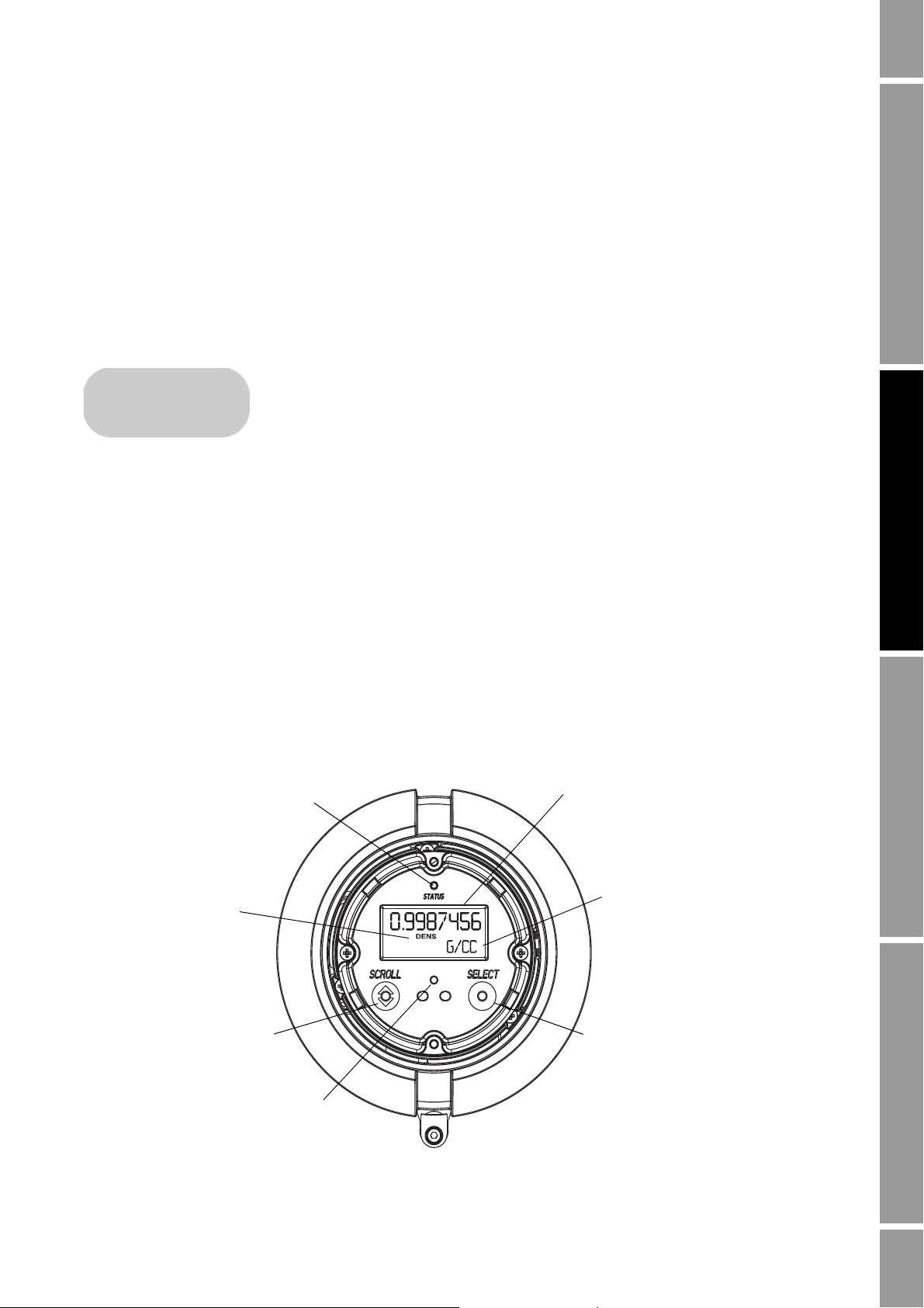
Current value
Units of measure
Process variable
Scroll optical switch Select optical switch
Optical switch indicator
Status LED
Using the Transmitter Display
2.1 Overview
The transmitter display provides basic configuration and management functionality.
This chapter describes the user interface of the transmitter display. The following
topics are discussed:
• Display components (see Section 2.2)
•Using the
• Using the display (see Section 2.4.2)
Note: The DIN rail mount transmitters do not have displays, and the field-mount transmitters can be
ordered with or without displays.
Not all configuration and use functions are available through the display. If you need the added
functionality, or if your transmitter does not have a display, you must use either ProLink II or the
Communicator to communicate with the transmitter.
Scroll and Select optical switches (see Section 2.3)
Using Display Using HART CommunicatorUsing ProLink IIBefore You Begin
2.2 Components
Figure 2-1 illustrates the display components.
Figure 2-1 Display components
Configuration and Use Manual 7
Page 16

Using the Transmitter Display
2.3 Using the optical switches
The
Scroll and Select optical switches are used to navigate the transmitter display. To activate an
optical switch, touch the glass in front of the optical switch or move your finger over the optical
switch close to the glass. The optical switch indicator will be solid red when a single switch is
activated, and will flash red when both switches are activated simultaneously.
Removing the display cover in an explosive atmosphere can cause an explosion. When using the
optical switches, do not remove the display cover. To activate an optical switch, touch the glass of the
display cover or move your finger over the switch close to the glass.
2.4 Using the display
In ordinary use, the
Units of measure line shows the measurement unit for that process variable.
the
Process variable line on the display shows the configured display variables, and
• See Section 8.14.4 for information on configuring the display variables.
• See Appendix H for information on the codes and abbreviations used for display variables.
If more than one line is required to describe the display variable, the
between the measurement unit and the additional description. For example, if the display is showing a
mass inventory value, the
name of the inventory (
MASSI).
Auto scroll may or may not be enabled:
Units of measure line alternates
Units of measure line alternates between the measurement unit (G) and the
• If Auto scroll is enabled, each configured display variable will be shown for the number of
seconds specified for Scroll rate.
• Whether Auto scroll is enabled or not, the operator can manually scroll through the configured
display variables by activating
Scroll.
For more information on using the display to view process variables or manage totalizers and
inventories, see Chapter 7.
2.4.1 Display menus
To enter the display menus, activate
will flash. Hold
Scroll and Select until the words SEE ALARM or OFF-LINE MAINT appear.
To move through a list of options, activate
To select from a list, scroll to the desired option, then activate
Scroll and Select simultaneously. The optical switch indicator
Scroll.
Select.
To exit a display menu without making any changes:
•Use the
• If the
EXIT option if available.
EXIT option is not available, activate Scroll and Select simultaneously, and hold until
the screen returns to the previous display.
2.4.2 Display password
Some of the display functions, such as the off-line menu and resetting totalizers, can be protected by a
password. For information about enabling and setting the password, refer to Section 8.14.
Note: If the petroleum measurement application is enabled on your transmitter, an off-line password
is always required to start, stop, or reset a totalizer, even if the display off-line password parameter is
disabled.
8 Micro Motion® LF-Series Transmitters
Page 17

Using the Transmitter Display
SX.XXXESY
Sign
For positive numbers,
leave this space
blank. For negative
numbers, enter a
dash (–).
Digits
Enter a four-digit
number; three digits
must fall to the right
of the decimal point.
E
Indicates
exponents.
Sign
Exponent
Enter the
power of 10 by
which the
digits will be
multiplied.
–8.100E 5
If a password is required, the word CODE? appears at the top of the password screen. Enter the digits
of the password one at a time by using
digit.
If you encounter the display password screen but do not know the password, wait 60 seconds without
activating any of the display optical switches. The password screen will time out automatically and
you will be returned to the previous screen.
2.4.3 Entering milliamp and frequency range values with the display
If you are using the display to change transmitter settings, the display uses a standard format and
procedure for entering range values for either mA or frequency outputs.
Enter range and scale values in scientific notation according to the following format:
Scroll to choose a number and Select to move to the next
Using Display Using HART CommunicatorUsing ProLink IIBefore You Begin
Example of range value format
The correct format for the number –810,000 is shown below:
To enter mA or frequency range values with the display:
Note: This procedure assumes that you are already at the correct point in the display menu to begin
entering the range values.
Scroll, if necessary, until the first space is either a minus sign (–) for a negative number or a
1.
blank space for a positive number.
2.
Select.
Scroll until the first digit is the correct number.
3.
4.
Select.
5.
Scroll until the second digit is the correct number.
Select.
6.
7.
Scroll until the third digit is the correct number.
8.
Select.
Scroll until the fourth digit is the correct number.
9.
10.
Select.
11.
Scroll, if necessary, until the sign for the exponent is either a dash (–) for a negative exponent
or a blank space for a positive exponent.
Configuration and Use Manual 9
Page 18

Using the Transmitter Display
12. Select.
13.
Scroll until the exponent is the correct power of 10.
14.
Scroll and Select simultaneously for four seconds to save and exit.
10 Micro Motion® LF-Series Transmitters
Page 19

Chapter 3
•FM AN F
•FM AN M
•FM CIO
•DIN AN
•DIN CIO
• DIN CIO FD
Connecting with ProLink II Software
3.1 Overview
ProLink II is a Microsoft
Micro Motion transmitters. It provides complete access to transmitter functions and
data.
This chapter provides basic information for connecting ProLink II to your
transmitter. The following topics and procedures are discussed:
• Requirements (see Section 3.2)
• Configuration upload/download (see Section 3.3)
• Connecting to a field-mount transmitter (see Section 3.4)
• Connecting to a DIN rail mount transmitter (see Section 3.5)
The instructions in this manual assume that users are already familiar with ProLink II software. For
more information on using ProLink II, or for detailed instructions on installing ProLink II, see the
ProLink II software manual, which is available on the Micro Motion web site
(www.micromotion.com).
®
Windows-based configuration and management tool for
Using Display Using HART CommunicatorUsing ProLink IIBefore You Begin
Note: ProLink II uses the Model 1500/1700/2500/2700 device descriptions for the LF-Series
field-mount transmitters. Accordingly, when you connect to an LF-Series transmitter, you will see a
Model 1500/1700/2500/2700 model code on the ProLink II screen.
3.2 Requirements
To use ProLink II with an LF-Series transmitter, the following are required:
• ProLink II v2.0 or later (some LF models require later versions of ProLink II)
• Signal converter, to convert the PC’s serial port signal to the signal used by the transmitter
- For RS-485 connections, an RS-485 to RS-232 signal converter. The Black Box
RS-232 <-> 2-wire RS-485 Interface Converter (Code IC521A-F) signal converter is
available from Micro Motion. Contact Micro Motion if you need an RS-485 signal
converter.
- For Bell 202 connections, a HART interface. The MACTek
Interface is available from Micro Motion. Contact Micro Motion if you need a HART
interface.
• 25-pin to 9-pin adapter (if required by your PC)
®
®
Viator® RS232 HART®
Async
Configuration and Use Manual 11
Page 20

Connecting with ProLink II Software
•FM AN F
•FM AN M
•FM CIO
3.3 ProLink II configuration upload/download
ProLink II provides a configuration upload/download function which allows you to save configuration
sets to your PC. This allows:
• Easy backup and restore of transmitter configuration
• Easy replication of configuration sets
Micro Motion recommends that all transmitter configurations be downloaded to a PC as soon as the
configuration is complete.
To access the configuration upload/download function:
1. Connect ProLink II to your transmitter as described in this chapter.
2. Open the
• To save a configuration file to a PC, use the
File menu.
Load from Xmtr to File option.
• To restore or load a configuration file to a transmitter, use the
option.
3.4 Connecting from a PC to an LF-Series field-mount transmitter
Depending on your transmitter, there are several options for connecting ProLink II to your transmitter.
See Table 3-1.
Note: Service port connections use standard settings, do not require transmitter configuration, and
are always available. Therefore, they are easy and convenient. However, service port connections
require opening the power supply compartment. Accordingly, service port connections should be used
only for temporary connections, and may require extra safety precautions.
Note: Due to the design of HART protocol, connections made using HART protocol are slower than
connections that use Modbus protocol. If you use HART protocol, you cannot open more than one
ProLink II window at a time.
Table 3-1 Connection options for field-mount transmitters
Connection Physical layer Protocol
Service port
(see Section 3.4.1)
RS-485 terminals or
RS-485 network
(see Section 3.4.2)
Primary mA terminals or
HART network
(see Section 3.4.3)
RS-485 Modbus ✓✓
RS-485 Modbus ✓
RS-485 HART ✓
Bell 202 HART ✓✓
FM AN A FM CIO
Send to Xmtr from File
Transm itter
12 Micro Motion® LF-Series Transmitters
3.4.1 Connecting to the service port
To connect to the service port, which is located in the non-intrinsically safe power
supply compartment (see Figure 3-1):
1. Attach the signal converter to the serial port of your PC, using a 25-pin to
9-pin adapter if required.
2. Open the cover to the wiring compartment.
Page 21
Connecting with ProLink II Software
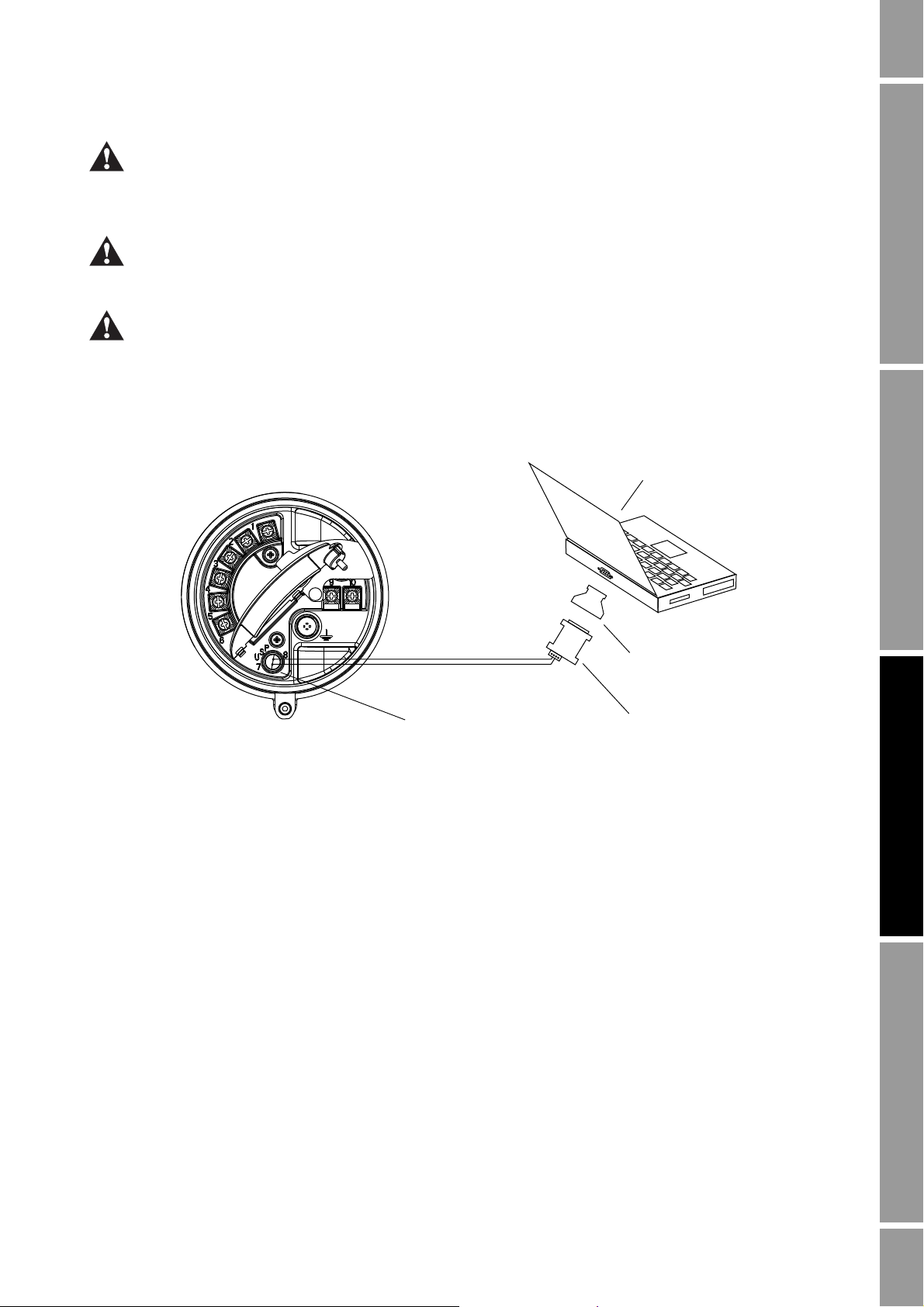
Service port
RS-485 to RS-232
signal converter
25-pin to 9-pin serial port
adapter (if necessary)
LF-Series field-mount transmitter
terminal compartment
RS-485/A
RS-485/B
PC
Opening the wiring compartment in a hazardous area can cause an explosion. When the transmitter is
in an explosive atmosphere, do not use the service port to connect to your transmitter.
3. Open the power supply compartment.
Opening the power supply compartment in a hazardous area while the power is on can cause an
explosion. Before using the service port to communicate with the transmitter in a hazardous area, make
sure the atmosphere is free of explosive gases.
Opening the power supply compartment can expose the operator to electric shock. Do not touch the
power supply wires or terminals while using the service port.
4. Connect the signal converter leads to the service port terminals. See Figure 3-1.
Figure 3-1 Service port connections to an LF-Series field-mount transmitter
Using Display Using HART CommunicatorUsing ProLink IIBefore You Begin
5. Start ProLink II software. From the Connection menu, click on
Connect to Device. In the
screen that appears, specify:
•
Protocol: Service Port
•
COM Port: as appropriate for your PC
All other parameters are set to service port required values and cannot be changed.
6. Click the
Connect button. ProLink will attempt to make the connection.
7. If an error message appears:
a. Swap the leads between the two service port terminals and try again.
Configuration and Use Manual 13
b. Ensure that you are using the correct COM port.
c. Check all the wiring between the PC and the transmitter.
Page 22

Connecting with ProLink II Software
•FM AN F
•FM AN M
RS-485 to RS-232
signal converter
25-pin to 9-pin serial port
adapter (if necessary)
LF-Series field-mount transmitter
terminal compartment
(FM AN transmitters only)
PC
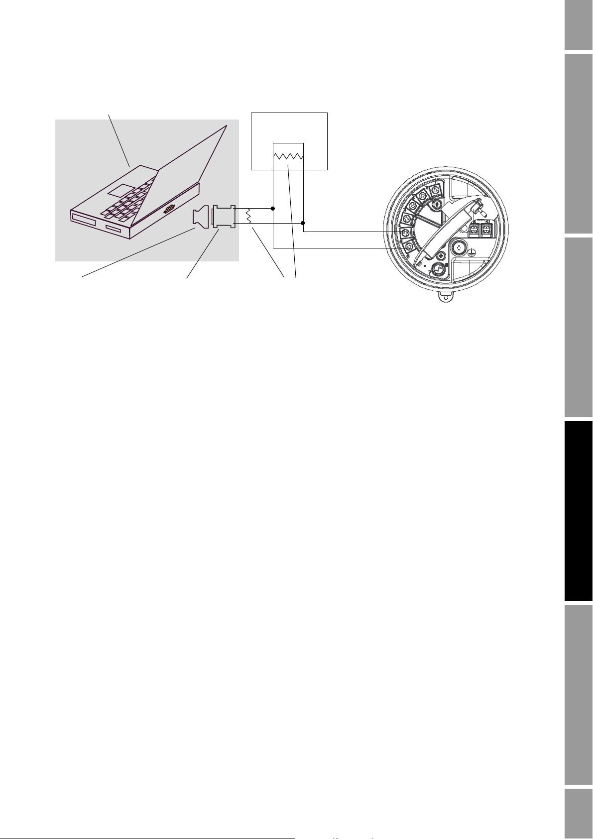
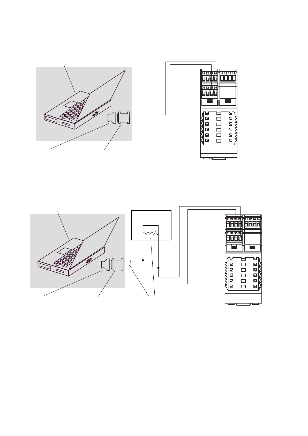
3.4.2 Connecting to the RS-485 terminals or an RS-485 network
To connect a PC to the RS-485 terminals or an RS-485 network:
1. Attach the signal converter to the serial port of your PC, using a 25-pin to 9-pin adapter if
required.
2. To connect to the RS-485 terminals, open the cover to the wiring compartment and connect the
signal converter leads to the transmitter terminals labeled
these terminals. See Figure 3-2.
3. To connect to an RS-485 network, connect the signal converter leads to any point in the
network. See Figure 3-3.
4. For long-distance communication, or if noise from an external source interferes with the
signal, install 120 Ω, 1/2 watt resistors in parallel with the output at both ends of the
communication segment.
Figure 3-2 RS-485 terminal connections to LF-Series FM AN transmitter
5 and 6, or to the output wires from
14 Micro Motion® LF-Series Transmitters
Page 23
Connecting with ProLink II Software
DCS or PLC
Add resistance if necessary
(see Step 4)
RS-485 to RS-232
signal converter
25-pin to 9-pin serial port
adapter (if necessary)
PC
Figure 3-3 RS-485 network connections to LF-Series FM AN transmitter
Using Display Using HART CommunicatorUsing ProLink IIBefore You Begin
5. Start ProLink II software. From the Connection menu, click on
Protocol, Baud Rate, Stop Bits, and Parity to the RS-485 values configured in the
6. Set
Connect to Device.
transmitter. See Section 8.15.
Note: If you do not know the transmitter’s RS-485 configuration, you can connect through the service
port, which always uses default settings, or you can use the Communicator or the display to view or
change the transmitter’s RS-485 configuration. Default RS-485 communication parameters are listed
in Table 8-8.
7. Set the
Address/Tag value to the Modbus or HART polling address configured for the
transmitter. The default Modbus address is 1; the default HART polling address is 0. See
Section 8.15.
8. Set the
9. Click the
COM Port value to the PC COM port assigned to this connection.
Connect button. ProLink will attempt to make the connection.
10. If an error message appears:
a. Swap the leads and try again.
b. You may be using incorrect connection parameters.
- Ensure you are using the correct COM port.
- Connect using the service port and check the RS-485 configuration. If required,
change the configuration or change your RS-485 connection parameters to match the
existing configuration.
- If you are unsure of the transmitter’s address, use the
Poll button in the Connect
window to return a list of all devices on the network.
c. Check all the wiring between the PC and the network. You may need to add resistance. See
Figure 3-3.
Configuration and Use Manual 15
Page 24
Connecting with ProLink II Software
•FM AN F
•FM AN M
•FM CIO
VIATOR
1 (+)
2 (–)
R2
See Step 4
R3
See Step 4
DCS or
PLC
R1
See Step 4
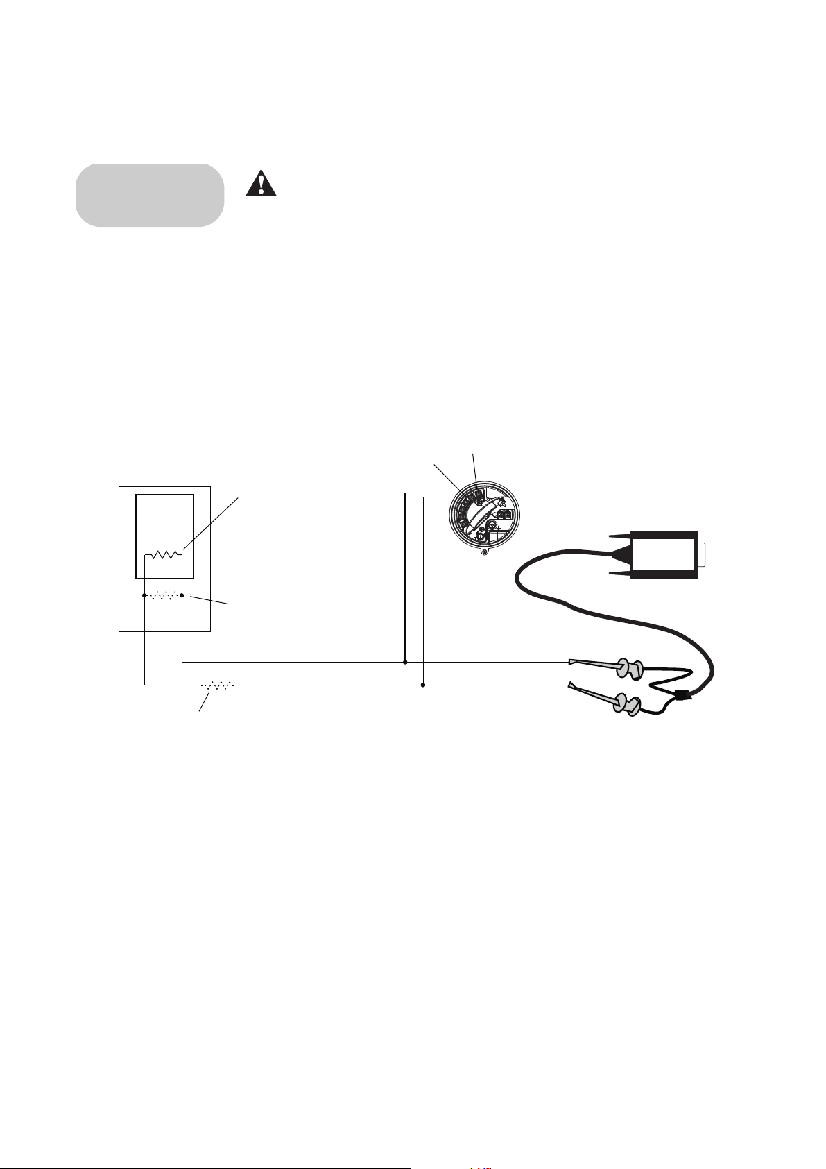
3.4.3 Connecting to the primary mA terminals or to a HART multidrop network
Connecting a HART device to the transmitter’s primary mA output
terminals could cause transmitter output error. Set control devices for
manual operation before connecting a HART interface to the transmitter’s
primary mA output loop.
To connect a PC to the primary mA terminals or to a HART multidrop network:
1. Attach the HART interface to the serial port of your PC.
2. To connect to the primary mA terminals, open the cover to the wiring compartment and
connect the HART interface leads to the terminals labeled
1 and 2, or to the output wires from
these terminals.
3. To connect to a HART multidrop network, connect the HART interface leads to any point on
the network.
Figure 3-4 HART/Bell202 connections to LF-Series field-mount transmitters
16 Micro Motion® LF-Series Transmitters
4. Add resistance as required. The Viator HART interface must be connected across a resistance
5. Start ProLink II software. From the Connection menu, click on
6. Set
7. Set the
8. Set the
of 250–600 Ω. To meet the resistance requirements, you may use any combination of resistors
R1, R2, and R3 (see Figure 3-4).
Protocol to HART Bell 202. Baud rate, Stop bits, and Parity are automatically set to the
values required by HART protocol.
Address/Tag value to the HART polling address configured for the transmitter. The
Connect to Device.
default HART polling address is 0. See Section 8.15 for information on the HART polling
address.
COM Port value to the PC COM port assigned to this connection.
Page 25

Connecting with ProLink II Software
•DIN AN
•DIN CIO
• DIN CIO FD
9. Set Master as appropriate:
• If another host such as a DCS is on the network, set
• If no other host is on the network, set
Master to Primary.
Note: The 375 Field Communicator is not a host.
10. Click the
Connect button. ProLink will attempt to make the connection.
11. If an error message appears:
a. You may be using incorrect connection parameters.
- Ensure you are using the correct COM port.
- If you are unsure of the transmitter’s address, use the
window to return a list of all devices on the network.
b. Check all the wiring between the PC and the transmitter.
c. Increase or decrease resistance.
3.5 Connecting from a PC to an LF-Series DIN rail mount transmitter
ProLink II software can communicate with an LF-Series DIN Rail mount
transmitter using:
• Modbus/RS-485 protocol (see Section 3.5.1
- Configurable connection
- SP (service port) standard connection
• A HART/Bell202 connection (see Section 3.5.2
Master to Secondary.
Poll button in the Connect
Using Display Using HART CommunicatorUsing ProLink IIBefore You Begin
)
)
Note: Service port connections use standard settings and do not require transmitter configuration.
Therefore, they are easy and convenient. However, service port connections are available only for the
10-second interval after power-up. See Step 5 in the following section.
Note: Due to the design of HART protocol, connections made using HART protocol are slower than
connections that use Modbus protocol. If you use HART protocol, you cannot open more than one
ProLink II window at a time.
3.5.1 Connecting to the RS-485 terminals or an RS-485 network
To connect a PC to the RS-485 terminals or an RS-485 network:
1. Attach the signal converter to the serial port of your PC, using a 25-pin to 9-pin adapter if
required.
2. To connect to the RS-485 terminals, connect the signal converter leads to terminals 33 and 34.
See Figure 3-5.
3. To connect to an RS-485 network, connect the signal converter leads to any point in the
network. See Figure 3-6.
4. For long-distance communication, or if noise from an external source interferes with the
signal, install 120 ohm, 1/2 watt resistors in parallel with the output at both ends of the
communication segment.
Configuration and Use Manual 17
Page 26
Connecting with ProLink II Software
RS-485/B
RS-485/A
RS-485 to RS-232
signal converter
25-pin to 9-pin serial port
adapter (if necessary)
PC
DCS or PLC
Add resistance if necessary
(see Step 4)
RS-485 to RS-232
signal converter
25-pin to 9-pin serial port
adapter (if necessary)
PC
RS-485 B
RS-485 A
Figure 3-5 RS-485 terminal connections to LF-Series DIN rail mount transmitter
Figure 3-6 RS-485 network connections to LF-Series DIN rail mount transmitter
5. Start ProLink II software. From the Connection menu, click on
screen that appears, specify connection parameters appropriate to your connection:
• Immediately after the transmitter is powered up, terminals 33 and 34 are available in
service port mode for 10 seconds. To connect during this period, set
Port, and set
Parity are set to standard values and cannot be changed (see Table 3-2).
COM port to the appropriate value for your PC. Baud rate, Stop bits, and
• If no connection is made during the 10-second period, the terminals are automatically
reset to the configured RS-485 communication parameters. To connect, set the connection
parameters to the values configured in your transmitter (see Table 3-2).
Connect to Device. In the
Protocol to Service
18 Micro Motion® LF-Series Transmitters
Page 27

Connecting with ProLink II Software
Table 3-2 Modbus connection parameters for ProLink II
Connection type
Connection parameter Configurable (RS-485 mode) SP standard (service port mode)
Protocol As configured in transmitter
(default = Modbus RTU)
Baud rate As configured in transmitter (default = 9600) 38,400
Stop bits As configured in transmitter (default = 1) 1
Parity As configured in transmitter (default = odd) None
Address/Tag Configured Modbus address (default = 1) 111
COM port COM port assigned to PC serial port COM port assigned to PC serial port
(1) Required value; cannot be changed by user.
Modbus RTU
(1)
(1)
(1)
(1)
(1)
6. Click the Connect button. ProLink will attempt to make the connection.
7. If an error message appears:
a. Swap the leads between the two terminals and try again.
b. Ensure you are using the correct COM port.
c. If you are in RS-485 mode, you may be using incorrect connection parameters.
- Connect using the service port and check the RS-485 configuration. If required,
change the configuration or change your RS-485 connection parameters to match the
existing configuration.
- If you are unsure of the transmitter’s address. use the
Poll button in the Connect
window to return a list of all devices on the network.
d. Check all the wiring between the PC and the transmitter.
Using Display Using HART CommunicatorUsing ProLink IIBefore You Begin
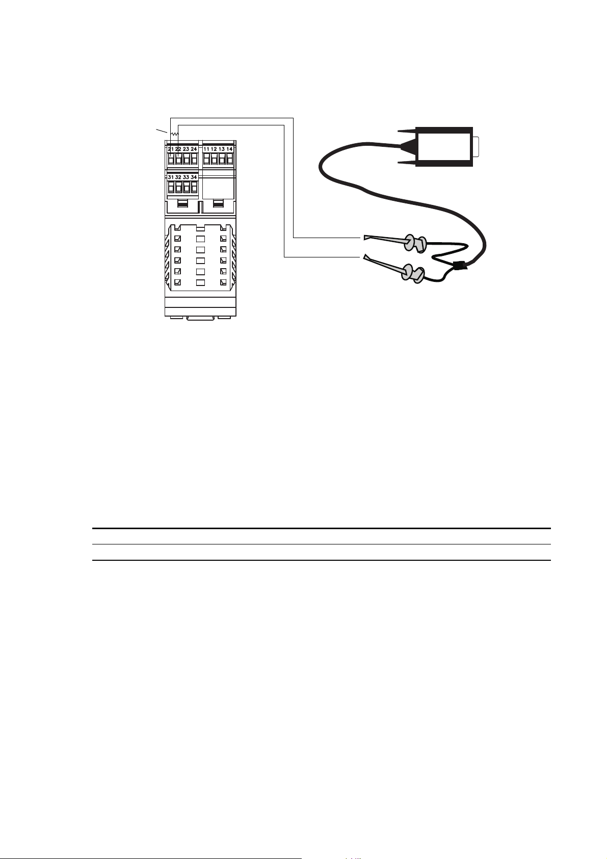
3.5.2 HART/Bell202 connections
Connecting a HART device to the transmitter’s primary mA output terminals could cause transmitter
output error. Set control devices for manual operation before connecting a HART interface to the
transmitter’s primary mA output loop.
HART/Bell202 connections are made through terminals 21 and 22. See Figure 3-7.
Configuration and Use Manual 19
Page 28
Connecting with ProLink II Software
VIATOR
250–600 Ω
Figure 3-7 HART/Bell202 connections to LF-Series DIN rail mount transmitter
Follow the instructions below to make the connection.
1. Connect the HART interface to your PC’s serial port. Then connect the leads of the HART
interface to terminals 21 and 22.
2. Add 250–600 Ω resistance to the connection, as required.
3. Start ProLink II software. From the Connection menu, click on
4. In the screen that appears, set
Protocol to HART Bell 202. Baud rate, Stop bits, and Parity
Connect to Device.
are automatically set to the values required by HART protocol. Specify the remaining
connection parameters as shown in Table 3-3.
Table 3-3 HART connection parameters for ProLink II
Connection parameter HART setting
Address/Tag Configured HART polling address (default = 0)
COM port COM port assigned to PC serial port
5. Click the
Connect button. ProLink will attempt to make the connection.
6. If an error message appears:
a. Ensure that you are using the correct COM port.
b. Check all the wiring between the PC and the transmitter.
c. Increase or decrease the resistance.
20 Micro Motion® LF-Series Transmitters
Page 29

Chapter 4
•FM AN F
•FM AN M
•FM CIO
•DIN AN
•DIN CIO
Connecting with the 375 Field Communicator
4.1 Overview
The 375 Field Communicator is a handheld configuration and management tool for
HART-compatible devices, including Micro Motion transmitters. It provides
complete access to transmitter functions and data.
Note: The DIN CIO FD transmitter can only be configured using ProLink II.
This chapter provides basic information for connecting the 375 Field Communicator
to your transmitter. The following topics and procedures are discussed:
• Communicator device descriptions (see Section 4.2)
• Connecting to a transmitter (see Section 4.3)
• Conventions used in this manual (see Section 4.4)
The instructions in this manual assume that users are already familiar with the Communicator and can
perform the following tasks:
• Turn on the Communicator
• Navigate the Communicator menus
• Establish communication with HART-compatible devices
• Transmit and receive configuration information between the Communicator and
HART-compatible devices
• Use the alpha keys to type information
• If you are unable to perform the tasks listed above, consult the Communicator manual before
attempting to use the software. The documentation is available on the Micro Motion website
(www.micromotion.com).
Using Display Using HART CommunicatorUsing ProLink IIBefore You Begin
4.2 Communicator device descriptions
Configuration and Use Manual 21
The Communicator uses the Model 1500/1700/2500/2700 device descriptions for the LF-Series
field-mount transmitters. Accordingly, when you connect to an LF-Series transmitter, you may see a
Model 1500/1700/2500/2700 model code on the Communicator display.
Table 4-1 lists the Communicator device descriptions that are available for LF-Series transmitters.
Page 30

Connecting with the 375 Field Communicator
•FM AN F
•FM AN M
•FM CIO
•DIN AN
•DIN CIO
Table 4-1 Transmitter models and device descriptions
Transmitter Device description
DIN AN 1500 Mass Flow
FM AN F 1000 Mass Flow
FM CIO 2000C Mass Flow
FM AN M 2000 Mass Flow
DIN CIO 2000C Mass Flow
To view the device descriptions that are installed on your 375 Field Communicator:
1. At the HART application menu, select
Utility.
2. Select
3. Select
Available Device Descriptions.
Micro Motion.
If you do not see the appropriate device description, contact Micro Motion Customer Support.
4.3 Connecting to a transmitter
You can connect the Communicator directly to the transmitter’s mA/HART
terminals or to a point on a HART network.
Note: If you are using the mA/HART terminals to report a process variable and also
for HART communication, see the transmitter installation manual for wiring
diagrams.
4.3.1 Connecting to communication terminals
To connect the Communicator directly to the transmitter’s mA/HART terminals:
Connecting a HART device to the transmitter’s primary mA output terminals could cause transmitter
output error. Set control devices for manual operation before connecting a HART interface to the
transmitter’s primary mA output loop.
1. If you are connecting to an LF-Series field-mount transmitter, open the cover to the wiring
compartment.
22 Micro Motion® LF-Series Transmitters
Opening the wiring compartment in a hazardous area can cause an explosion. When the transmitter is
in an explosive atmosphere, do not use the mA terminals to connect to your transmitter.
2. Connect the Communicator leads to the transmitter’s primary mA output terminals:
• FM transmitters: terminals 1 and 2 (see Figure 4-1)
• DIN transmitters: terminals 21 and 22 (see Figure 4-2)
3. The Communicator must be connected across a resistance of 250–600 Ω. Add resistance to the
connection. See Figure 4-1.
Page 31

Connecting with the 375 Field Communicator
Communicator
250–600 Ω
resistance
1
2
–
+
250–600 Ω
resistance
+–
Communicator
Figure 4-1 Connecting to communication terminals – field-mount transmitters
Figure 4-2 Connecting to communication terminals – DIN rail mount transmitters
Using Display Using HART CommunicatorUsing ProLink IIBefore You Begin Using Display Using HART CommunicatorUsing ProLink IIBefore You Begin Using Display Using HART CommunicatorUsing ProLink IIBefore You Begin Using Display Using HART CommunicatorUsing ProLink IIBefore You Begin
Configuration and Use Manual 23
Page 32

Connecting with the 375 Field Communicator
Tr an s m it t ers
Communicator
Master
device
250–600 Ω resistance
(if necessary)
4.3.2 Connecting to a multidrop network
The Communicator can be connected to any point in a multidrop network. See Figure 4-3.
Note: The Communicator must be connected across a resistance of 250–600
connection if necessary.
Figure 4-3 Connecting to a multidrop network
4.4 Conventions used in this manual
All Communicator procedures assume that you are starting at the on-line menu. “Online” appears on
the top line of the Communicator main menu when the Communicator is at the on-line menu.
Ω . Add resistance to the
4.5 HART Communicator safety messages and notes
Users are responsible for responding to safety messages (e.g., warnings) and notes that appear on the
Communicator. Safety messages and notes that appear on the Communicator are not discussed in this
manual.
24 Micro Motion® LF-Series Transmitters
Page 33

Chapter 5
Finish
Start
Apply power
Perform a
loop test
Tr im mA
outputs (if
necessary)
Zero the
flowmeter
Flowmeter Startup
5.1 Overview
This chapter describes the procedures you should perform the first time you start the flowmeter. You
do not need to use these procedures every time you cycle power to the flowmeter.
The following procedures are discussed:
• Applying power to the flowmeter (see Section 5.2)
• Zeroing the flowmeter (see Section 5.5)
• Performing a loop test on the transmitter outputs (see Section 5.3)
• Trimming the mA outputs (see Section 5.4)
Figure 5-1 provides an overview of the flowmeter startup procedures.
Figure 5-1 Startup procedures
Required Configuration Optional ConfigurationUsing TransmitterStartup
Note: All ProLink II procedures provided in this chapter assume that your computer is already
connected to the transmitter and you have established communication. All ProLink II procedures also
assume that you are complying with all applicable safety requirements. See Chapter 3 for more
information.
Note: If you are using AMS, the AMS interface will be similar to the ProLink II interface described in
this chapter.
Note: All Communicator procedures provided in this chapter assume that you are starting from the
“Online” menu. See Chapter 4 for more information.
Configuration and Use Manual 25
Page 34

Flowmeter Startup
5.2 Applying power
Before you apply power to the flowmeter, close and tighten all housing covers.
Operating the flowmeter without covers in place creates electrical hazards that can cause death, injury,
or property damage. Make sure safety barrier partition and covers for the field-wiring, circuit board
compartments, electronics module, and housing are all in place before applying power to the
transmitter.
Using the service port to communicate with an LF-Series field-mount transmitter in a hazardous area
can cause an explosion. Before using the service port to communicate with the transmitter in a
hazardous area, make sure the atmosphere is free of explosive gases.
Turn on the electrical power at the power supply. The flowmeter will automatically perform
diagnostic routines. When the flowmeter has completed its power-up sequence:
• For LF-Series field-mount transmitters under normal conditions, the status LED on the display
will turn green and begin to flash,
• For LF-Series DIN rail mount transmitters under normal conditions, the status LED will turn
green.
• If the status LED exhibits different behavior, an alarm condition is present or transmitter zero
is in progress. See Section 7.4.
5.2.1 Communication methods after power-up
For LF-Series field-mount transmitters, all communication methods supported by the transmitter are
available immediately after power-up.
For LF-Series DIN rail mount transmitters:
• If you are using the Communicator, or ProLink II with HART protocol (HART/Bell202), you
can establish communication with the transmitter immediately after power-up, using terminals
21 and 22. See Chapter 4 for more information on using the Communicator, or Chapter 3 for
more information on using ProLink II.
• If you are using ProLink II via the RS-485 physical layer, terminals 33 and 34 are available in
service port mode for 10 seconds immediately after power-up. If no connection is made during
this period, the terminals are automatically reset to the configured Modbus communication
parameters. Be sure to set the ProLink II connection parameters appropriately. See Chapter 3.
5.3 Performing a loop test
A loop test is a means to:
• Verify that analog outputs (mA and frequency) are being sent by the transmitter and received
accurately by the receiving devices
• Determine whether or not you need to trim the mA outputs
• Select and verify the discrete output voltage
• Read the discrete input
Perform a loop test on all inputs and outputs available on your transmitter. Before performing the loop
tests, ensure that your transmitter terminals are configured for the input/outputs that will be used in
your application (see Section 6.2).
You can perform a loop test with the display, with ProLink II, or the Communicator.
26 Micro Motion® LF-Series Transmitters
Page 35

Flowmeter Startup
•FM AN F
•FM AN M
•FM CIO
5.3.1 Loop testing with the display
Note the following:
• The display cannot be used to test the discrete input. If your transmitter has a discrete input,
• The mA reading does not need to be exact. You will correct differences when you trim the mA
• While the output is fixed:
See Figure 5-2 for the loop test procedure. Not all options are available on all
transmitters.
use ProLink II or a Communicator to perform the discrete input loop test.
output. See Section 5.4.
- Dots traverse the top line of the display.
- The status LED blinks yellow.
• When the output is unfixed:
- The dots disappear.
- The status LED returns to the state it was in before the output was fixed.
Required Configuration Optional ConfigurationUsing TransmitterStartup
Configuration and Use Manual 27
Page 36

Flowmeter Startup
Set MAO1
Set MAO2
OFF-LINE MAINT
Scroll and Select
simultaneously for 4 seconds
Set FO
Set DO1
Set DO2
1 KHz
10 KHz
Read output at
receiving device
Read output at
receiving device
Loop test successful
Select to stop simulation
Scroll
Exit
Check output wiring
Troubleshoot output
Correct?
Read output at
receiving device
ON
OFF
4 mA
12 mA
20 mA
Ye s No output
Correct?
Correct?
OFF-LINE SIM
Scroll
Scroll
Select
Select
Select
Scroll
Scroll
Select
Select
Scroll
Select
Scroll
Select
Select
Figure 5-2 Display – Loop test procedure
28 Micro Motion® LF-Series Transmitters
Page 37

Flowmeter Startup
•FM AN F
•FM AN M
•FM CIO
•DIN AN
•DIN CIO
• DIN CIO FD
Test
Fix Milliamp 1
Fix Milliamp 2
ProLink Menu
Fix Freq Out
Read Discrete InFix Discrete Out 1
Fix Discrete Out 2
Enter pulses/second
(Hz) value
Toggle remote input
device
Read output at
receiving device
Read output at
receiving device
Loop test successful
UnFix
Check output wiring
Troubleshoot output
Correct?
Read output at
receiving device
ON or OFF
Verify reading at
transmitter
Enter mA value
Ye s No output
Correct?
Fix FrequencyFix mA Fix Discrete Output
Correct? Correct?
Loop test successful Check input wiring
Troubleshoot remote
device
Ye s No input
5.3.2 Loop testing with ProLink II
See Figure 5-3 for the loop test procedure. Not all options are available on all
transmitters.
Note the following:
• The mA reading does not need to be exact. You will correct differences
when you trim the mA output. See Section 5.4.
Figure 5-3 ProLink II – Loop test procedure
Required Configuration Optional ConfigurationUsing TransmitterStartup
Configuration and Use Manual 29
Page 38

Flowmeter Startup
•FM AN F
•FM AN M
•FM CIO
•DIN AN
•DIN CIO
Diag/Service
Loop test
Fix Analog Out 1
Fix Analog Out 2
On-Line Menu
Fix Frequency Out
Read Discrete InFix Discrete Out 1
Fix Discrete Out 2
10 kHz
Other
Toggle remote input
device
Read output at
receiving device
Read output at
receiving device
Loop test successful
OK or END to unfix
output
Check output wiring
Troubleshoot output
Read output at
receiving device
ON or OFF
Verify reading at
transmitter
4 mA
20 mA
Other
Ye s No output
Near
specified value? Correct? Correct? Correct?
Loop test successful Check input wiring
Troubleshoot remote
device
Ye s No input
5.3.3 Loop testing with a Communicator
See Figure 5-4 for the loop test procedure. Not all options are available on all
transmitters.
Note the following:
• If you are testing the primary mA output, the HART/Bell202 signal to the
Communicator will affect the reading. Disconnect the Communicator before
reading the output, then reconnect the Communicator and resume the loop
test after taking the reading.
• The mA reading does not need to be exact. You will correct differences
when you trim the mA output. See Section 5.4.
Figure 5-4 Communicator – Loop test procedure
30 Micro Motion® LF-Series Transmitters
Page 39

Flowmeter Startup
•FM AN F
•FM AN M
•FM CIO
•DIN AN
•DIN CIO
• DIN CIO FD
5.4 Trimming the milliamp outputs
Trimming the mA output creates a common measurement range between the transmitter and the device
that receives the mA output. For example, a transmitter might send a 4 mA signal that the receiving
device reports incorrectly as 3.8 mA. If the transmitter output is trimmed correctly, it will send a
signal appropriately compensated to ensure that the receiving device actually indicates a 4 mA signal.
You must trim the mA output at both the 4 mA and 20 mA points to ensure appropriate compensation
across the entire output range.
Perform a milliamp trim on all mA outputs available on your transmitter. Before performing the trim,
ensure that your transmitter terminals are configured for the input/outputs that will be used in your
application (see Section 6.2).
You can trim the outputs with ProLink II or a Communicator.
5.4.1 Milliamp output trim with ProLink II
See Figure 5-5 for the mA output trim procedure.
Note the following:
• If you are trimming the primary mA output, and you are connected to the
transmitter via HART/Bell202, the HART/Bell202 signal to ProLink II will
affect the reading. Disconnect ProLink II before reading the output, then
reconnect and resume the trim, after taking the reading. If you are using any
other protocol, this is not required.
• Any trimming performed on the output should not exceed ± 200 microamps.
If more trimming is required, contact Micro Motion customer support.
Required Configuration Optional ConfigurationUsing TransmitterStartup
Configuration and Use Manual 31
Page 40

Flowmeter Startup
Calibration
ProLink Menu
Read mA output at
receiving device
Equal?
Enter receiving device
value in
Enter Meas
Read mA output at
receiving device
Milliamp Trim 1
Milliamp Trim 2
No Yes
OK
Do Cal
Read mA output at
receiving device
Equal?
Enter receiving device
value in
Enter Meas
Read mA output at
receiving device
No
Do Cal
DONE
4 mA trim 20 mA trim
OK
Yes
Figure 5-5 ProLink II – mA output trim procedure
32 Micro Motion® LF-Series Transmitters
Page 41

Flowmeter Startup
•FM AN F
•FM AN M
•FM CIO
•DIN AN
•DIN CIO
Read mA output at
receiving device
Equal?
Enter receiving device
value at
Communicator
Read mA output at
receiving device
Trim Analog Out 1
Trim Analog Out 2
No
ENTER
Yes
ENTER
OK
ENTER
Read mA output at
receiving device
OK
4 mA trim 20 mA trim
Diag/Service
On-Line Menu
Read mA output at
receiving device
Equal?
Enter receiving device
value at
Communicator
No
ENTER
ENTER
Yes
ENTER
5.4.2 Milliamp output trim with a Communicator
See Figure 5-6 for the mA output trim procedure.
Note the following:
• If you are trimming the primary mA output, the HART/Bell202 signal to the
Communicator will affect the reading. Disconnect the Communicator before
reading the output, then reconnect and resume the trim, after taking the
reading.
• Any trimming performed on the output should not exceed ± 200 microamps.
If more trimming is required, contact Micro Motion customer support.
• The receiving device value that you enter in the Communicator can contain
up to two decimal places.
Figure 5-6 Communicator – mA output trim procedure
Required Configuration Optional ConfigurationUsing TransmitterStartup
Configuration and Use Manual 33
Page 42

Flowmeter Startup
5.5 Zeroing the flowmeter
Zeroing the flowmeter establishes the flowmeter’s point of reference when there is no flow.
When you zero the flowmeter, you may need to adjust the zero time parameter. Zero time is the
amount of time the transmitter takes to determine its zero-flow reference point. The default zero time
is 20 seconds.
•A long zero time may produce a more accurate zero reference but is more likely to result in a
zero failure. This is due to the increased possibility of noisy flow, which causes incorrect
calibration.
•A short zero time is less likely to result in a zero failure but may produce a less accurate zero
reference.
For most applications, the default zero time is appropriate.
Note: In some menus, a convergence limit parameter is displayed. Micro Motion recommends that you
use the default value for convergence limit.
Note: Do not zero the flowmeter if a high severity alarm is active. Correct the problem, then zero the
flowmeter. You may zero the flowmeter if a low severity alarm is active. See Section 7.4 for
information on viewing transmitter status and alarms.
You can zero the flowmeter with the display (if the transmitter has a display), ProLink II, the
Communicator, or with the Zero button on the transmitter (DIN rail mount transmitters only).
If the zero procedure fails, see Section 11.6 for troubleshooting information.
5.5.1 Preparing for zero
To prepare for the zero procedure:
1. Apply power to the flowmeter. Allow the flowmeter to warm up for approximately 20 minutes.
2. Run the process fluid through the sensor until the sensor temperature reaches the normal
process operating temperature.
3. Close the shutoff valve downstream from the sensor.
4. Ensure that the sensor is completely filled with fluid.
5. Ensure that the process flow has completely stopped.
If fluid is flowing through the sensor, the sensor zero calibration may be inaccurate, resulting in
inaccurate process measurement. To improve the sensor zero calibration and measurement accuracy,
ensure that process flow through the sensor has completely stopped.
34 Micro Motion® LF-Series Transmitters
Page 43

Flowmeter Startup
•FM AN F
•FM AN M
•FM CIO
TEST FAIL
ZERO and YES?
alternate on display
TEST OK
Troubleshoot
Select
OFF-LINE MAINT
Scroll and Select
simultaneously for 4 seconds
OFF-LINE ZERO
Scroll
Scroll
Select
Select
Dots traverse top line
of display
Exit
Select
5.5.2 Zeroing with the display
Figure 5-7 Display – Flowmeter zero procedure
See Figure 5-7 for the flowmeter zero procedure.
Note the following:
• If the off-line menu has been disabled, you will not be able to zero the
transmitter with the display. For information about enabling and disabling
the off-line menu, see Section 8.14.1.
• You cannot change the zero time with the display. If you need to change the
zero time, you must use the Communicator or ProLink II software.
Required Configuration Optional ConfigurationUsing TransmitterStartup
Configuration and Use Manual 35
Page 44

Flowmeter Startup
•FM AN F
•FM AN M
•FM CIO
•DIN AN
•DIN CIO
• DIN CIO FD
ProLink Menu
Calibration
Zero Calibration
Modify zero time if
required
Zero
Calibration Failure
light turns red?
Calibration in Progress
light turns red
Calibration in Progress
light turns green?
Troubleshoot
Done
5.5.3 Zeroing with ProLink II
Figure 5-8 ProLink II – Flowmeter zero procedure
See Figure 5-8 for the flowmeter zero procedure.
36 Micro Motion® LF-Series Transmitters
Page 45

Flowmeter Startup
•FM AN F
•FM AN M
•FM CIO
•DIN AN
•DIN CIO
On-Line Menu
Diag/Service
Calibration
Modify zero time if
required
Auto Zero Failed
Calibration in Progress
message
Auto Zero Complete
Troubleshoot
OK
Auto zero
Perform auto zero
OK
5.5.4 Zeroing with a Communicator
Figure 5-9 Communicator – Flowmeter zero procedure
See Figure 5-9 for the flowmeter zero procedure.
Required Configuration Optional ConfigurationUsing TransmitterStartup
Configuration and Use Manual 37
Page 46

Flowmeter Startup
•DIN AN
•DIN CIO
• DIN CIO FD
Done
Press Zero button
Status LED flashes yellow
Status LED
turns solid red?
Troubleshoot
Status LED
turns solid green or
solid yellow?
5.5.5 Zeroing with the Zero button
Figure 5-10 Zero button – Flowmeter zero procedure
See Figure 5-10 for the flowmeter zero procedure.
Note the following:
• You cannot change the zero time with the Zero button. If you need to change
the zero time, you must use the Communicator or ProLink II software.
• The Zero button is located on the front panel of the transmitter. To press it,
use a fine-pointed object such as the end of a paperclip. Hold the button
down until the status LED on the front panel begins to flash yellow.
38 Micro Motion® LF-Series Transmitters
Page 47

Chapter 6
•FM AN M
•FM CIO
•DIN CIO
• DIN CIO FD
Required Transmitter Configuration
6.1 Overview
This chapter describes the configuration procedures that are usually required when a transmitter is
installed for the first time.
The following procedures are discussed:
• Configuring transmitter terminals (see Section 6.2)
• Configuring measurement units (see Section 6.3)
• Configuring the mA output(s) (see Section 6.4)
• Configuring the frequency output (see Section 6.5)
• Configuring the discrete output (see Section 6.6)
• Configuring the discrete input (see Section 6.6.1)
This chapter provides basic flowcharts for each procedure. For more detailed flowcharts, see the
flowcharts for your transmitter and communication tool, provided in the appendices to this manual.
Default values and ranges for the parameters described in this chapter are provided in Appendix A.
Required Configuration Optional ConfigurationUsing TransmitterStartup
For optional transmitter configuration parameters and procedures, see Chapter 8.
Note: All ProLink II procedures provided in this chapter assume that your computer is already
connected to the transmitter and you have established communication. All ProLink II procedures also
assume that you are complying with all applicable safety requirements. See Chapter 3 for more
information.
Note: If you are using AMS, the AMS interface will be similar to the ProLink II interface described in
this chapter.
Note: All Communicator procedures provided in this chapter assume that you are starting from the
“Online” menu. See Chapter 4 for more information.
6.2 Configuring transmitter terminals
Configuration of the transmitter terminals has consequences for many following
configuration options. Therefore, it is important to configure or verify terminal
configuration at the beginning of transmitter configuration.
• If you have an FM CIO or DIN CIO transmitter, you must configure the
channels. Refer to Section 6.2.1.
• If you have a DIN CIO FD transmitter, you must configure the channels to
specific values. Refer to Section 6.2.2.
• If you have an FM AN M transmitter, you must specify whether terminals
3 and 4 will operate as a frequency output (FO) or a discrete output (DO).
Refer to Section 6.2.3.
Configuration and Use Manual 39
Page 48

Required Transmitter Configuration
•FM CIO
•DIN CIO
Communicator
ProLink II
Channel Configuration
Configuration
On-Line Menu
Detailed Setup
Config outputs
Channel setup
On-Line MenuProLink Menu
6.2.1 Configuring the channels
The six input/output terminals provided on these transmitters are organized into
three pairs, or sets. These pairs are called Channels A, B, and C.
The outputs and variable assignments that you can configure are controlled by the
channel configuration. Table 6-1 shows how each channel may be configured, to
what default variable each configuration is set, and the power options for each
channel.
Table 6-1 Channel configuration options
.
Terminals
Default process
variable assignmentChannel DIN CIO FM CIO Configuration option Power
A 21 & 22 1 & 2 mA output 1
(with Bell 202 HART)
B 23 & 24 3 & 4 mA output 2 (default)
(1)
Frequency output (FO) Mass flow
Discrete output 1 (DO1)
C 31 & 32 5 & 6 FO (default)
(3)(4)
(3)
Discrete output 2 (DO2) Flow switch
Discrete input (DI) None
(1) If set to MAO2, internal power is required.
(2) If set to external power, you must provide power to the outputs.
(3) Because DO1 uses the same circuitry as the frequency output, it is not possible to configure both FO and DO1. If both a frequency
output and a discrete output are required, configure Channel B as the FO and Channel C as DO2.
(4) When configured for two FOs (dual pulse), FO2 is generated from the same FO signal sent to the first FO. FO2 is electrically isolated
but not independent.
Mass flow Internal
Density Internal or external
Fwd/Rev
Mass flow Internal or external
(2)
(2)
To configure the channels, see the menu flowcharts in Figure 6-1.
Figure 6-1 Configuring the channels
40 Micro Motion® LF-Series Transmitters
Page 49

Required Transmitter Configuration
• DIN CIO FD
ProLink II
Channel Configuration
Configuration
ProLink Menu
6.2.2 Configuring the channels for the Filling and Dosing application
The six input/output terminals provided on the DIN CIO FD transmitter are
organized into three pairs, or sets. These pairs are called Channels A, B, and C.
Table 6-1 shows how each channel must be configured for the Filling and Dosing
application to function correctly. It may help to refer to Chapter 11.
Table 6-2 Filling and Dosing channel configuration
.
Process variable
Channel Terminals Configured as
A 21 & 22 mA output 1
(with Bell 202 HART)
B 23 & 24 Discrete output 1 (DO1) Fwd/Rev External
C 31 & 32 Discrete output 2 (DO2) Flow switch External
(1) You must provide power to the outputs.
assignment Power
Mass flow Internal
To configure the channels, see the menu flowcharts in Figure 6-1.
Figure 6-2 Configuring the channels
(1)
(1)
Required Configuration Optional ConfigurationUsing TransmitterStartup
Configuration and Use Manual 41
Page 50

Required Transmitter Configuration
•FM AN M
CommunicatorProLink II
Frequency/Discrete Output
Configuration
On-Line Menu
Detailed Setup
Config outputs
FO/DO config
ProLink Menu
•FM AN F
•FM AN M
•FM CIO
•DIN AN
•DIN CIO
• DIN CIO FD
6.2.3 Configuring terminals 3 and 4
On these transmitters, terminals 3 and 4 can operate as a frequency output (FO) or a
discrete output (DO). The default is FO.
To configure the terminals, see the menu flowcharts in Figure 6-3.
Figure 6-3 Configuring terminals 3 and 4
6.3 Configuring the measurement units
For each process variable, the transmitter must be configured to use the
measurement unit appropriate to your application.
For some transmitters, the density and temperature process variables can be viewed
but cannot be assigned to an output. See Table 6-3.
Table 6-3 Transmitter models and available process variables
Transmitter Mass flow Volume flow Density Temperature
FM AN F ✓✓✓
FM AN M ✓✓✓✓
FM CIO ✓✓✓✓
DIN AN ✓✓✓
DIN CIO ✓✓✓✓
DIN CIO FD ✓
(1) Can be viewed, but cannot be assigned to an output.
To configure measurement units, see the menu flowcharts in Figure 6-4. For details on measurement
units for each process variable, see Sections 6.3.1 through 6.3.4.
(1)
(1)
(1)
✓
(1)
✓
42 Micro Motion® LF-Series Transmitters
Page 51

Required Transmitter Configuration
Communicator DisplayProLink II
Flow / Density /
Temperature / Pressure
Configuration
On-Line Menu
Detailed Setup
Config fld dev var
Off-line maint
Off-line configure
Configure units
ProLink Menu
Figure 6-4 Configuring measurement units
6.3.1 Mass flow units
Required Configuration Optional ConfigurationUsing TransmitterStartup
Table 6-4 Mass flow measurement units
G/S g/s g/s Grams per second
G/MIN g/min g/min Grams per minute
G/H g/hr g/h Grams per hour
KG/S kg/s kg/s Kilograms per second
KG/MIN kg/min kg/min Kilograms per minute
KG/H kg/hr kg/h Kilograms per hour
KG/D kg/day kg/d Kilograms per day
T/MIN mTon/min MetTon/min Metric tons per minute
T/H mTon/hr MetTon/h Metric tons per hour
T/D mTon/day MetTon/d Metric tons per day
LB/S lbs/s lb/s Pounds per second
LB/MIN lbs/min lb/min Pounds per minute
LB/H lbs/hr lb/h Pounds per hour
LB/D lbs/day lb/d Pounds per day
ST/MIN sTon/min STon/min Short tons (2000 pounds) per minute
ST/H sTon/hr STon/h Short tons (2000 pounds) per hour
ST/D sTon/day STon/d Short tons (2000 pounds) per day
LT/H lTon/hr LTon/h Long tons (2240 pounds) per hour
LT/D lTon/day LTon/d Long tons (2240 pounds) per day
SPECL special Spcl Special unit (see Section 8.4)
The default mass flow measurement unit is
g/s. See Table 6-4 for a complete list of mass flow
measurement units.
If the mass flow unit you want to use is not listed, you can define a special measurement unit for mass
flow (see Section 8.4).
Mass flow unit
Unit descriptionDisplay ProLink II Communicator
Configuration and Use Manual 43
Page 52

Required Transmitter Configuration
6.3.2 Volume flow units
The default volume flow measurement unit is
L/s. See Table 6-5 for a complete list of volume flow
measurement units.
If the volume flow unit you want to use is not listed, you can define a special measurement unit for
volume flow (see Section 8.4).
Table 6-5 Volume flow measurement units
Volume flow unit
Display ProLink II Communicator Unit description
CUFT/S ft3/sec Cuft/s Cubic feet per second
CUF/MN ft3/min Cuft/min Cubic feet per minute
CUFT/H ft3/hr Cuft/h Cubic feet per hour
CUFT/D ft3/day Cuft/d Cubic feet per day
M3/S m3/sec Cum/s Cubic meters per second
M3/MIN m3/min Cum/min Cubic meters per minute
M3/H m3/hr Cum/h Cubic meters per hour
M3/D m3/day Cum/d Cubic meters per day
USGPS US gal/sec gal/s U.S. gallons per second
USGPM US gal/min gal/min U.S. gallons per minute
USGPH US gal/hr gal/h U.S. gallons per hour
USGPD US gal/d gal/d U.S. gallons per day
MILG/D mil US gal/day MMgal/d Million U.S. gallons per day
L/S l/sec L/s Liters per second
L/MIN l/min L/min Liters per minute
L/H l/hr L/h Liters per hour
MILL/D mil l/day ML/d Million liters per day
UKGPS Imp gal/sec Impgal/s Imperial gallons per second
UKGPM Imp gal/min Impgal/min Imperial gallons per minute
UKGPH Imp gal/hr Impgal/h Imperial gallons per hour
UKGPD Imp gal/day Impgal/d Imperial gallons per day
BBL/S barrels/sec bbl/s Barrels per second
BBL/MN barrels/min bbl/min Barrels per minute
BBL/H barrels/hr bbl/h Barrels per hour
BBL/D barrelsday bbl/d Barrels per day
SPECL special Spcl Special unit (see Section 8.4)
(1)
(1)
(1)
(1)
(1) Unit based on oil barrels (42 U.S gallons).
44 Micro Motion® LF-Series Transmitters
Page 53

Required Transmitter Configuration
6.3.3 Density units
The default density measurement unit is
g/cm3. See Table 6-4 for a complete list of density
measurement units.
Table 6-6 Density measurement units
Density unit
Unit descriptionDisplay ProLink II Communicator
SGU SGU SGU Specific gravity unit (not temperature corrected)
G/CM3 g/cm3 g/Cucm Grams per cubic centimeter
G/L g/l g/L Grams per liter
G/ML g/ml g/mL Grams per milliliter
KG/L kg/l kg/L Kilograms per liter
KG/M3 kg/m3 kg/Cum Kilograms per cubic meter
LB/GAL lbs/Usgal lb/gal Pounds per U.S. gallon
LB/CUF lbs/ft3 lb/Cuft Pounds per cubic foot
LB/CUI lbs/in3 lb/CuIn Pounds per cubic inch
Not configurable degAPI degAPI API gravity (API feature only)
ST/CUY sT/yd3 STon/Cuyd Short ton per cubic yard
Required Configuration Optional ConfigurationUsing TransmitterStartup
6.3.4 Temperature units
The default temperature measurement unit is
degC. See Table 6-7 for a complete list of temperature
measurement units.
Table 6-7 Temperature measurement units
Temperature unit
Unit descriptionDisplay ProLink II Communicator
°C degC degC Degrees Celsius
°F degF degF Degrees Fahrenheit
°R degR degR Degrees Rankine
°K degK Kelvin Degrees Kelvin
Configuration and Use Manual 45
Page 54

Required Transmitter Configuration
•FM AN F
•FM AN M
•FM CIO
•DIN AN
•DIN CIO
• DIN CIO FD
Communicator DisplayProLink II
Analog output
Configuration
On-Line Menu
Configure outputs
Analog output 1 / 2
Off-line maint
Off-line configure
Configure mA1 / mA2
AO setup
AN transmitters CIO transmitters
ProLink Menu
6.4 Configuring the mA output(s)
All transmitters have one mA output, called the primary mA output. Some
transmitters always have a secondary mA output, and some transmitters can be
configured for a secondary mA output (see Section 6.2, page 39). The menu options
for the secondary mA output will appear only if a secondary mA output is present
on your transmitter.
Note: Configure the transmitter for the required input/output types before configuring individual
outputs. See Section 6.2.
The following parameters must be set for the primary mA output, and for the secondary mA output if
it is present:
• Process variable
• Upper range value (URV) and lower range value (LRV)
• AO (analog output) cutoff
• Fault indicator and fault value
An additional parameter—added damping—can be configured if required.
To configure the mA outputs, see the menu flowcharts in Figure 6-4. For details on mA output
parameters, see Sections 6.4.1 through 6.4.5.
Figure 6-5 Configuring the mA output(s)
Note: If you use the display to configure the mA output, you can configure only the process variable
and the range. To configure other mA output parameters, use ProLink II or the Communicator.
46 Micro Motion® LF-Series Transmitters
Page 55

Required Transmitter Configuration
•FM AN F
•FM AN M
•FM CIO
•DIN AN
•DIN CIO
• DIN CIO FD
•FM AN F
•FM AN M
•FM CIO
•DIN AN
•DIN CIO
• DIN CIO FD
6.4.1 Configuring the process variable
You can configure the process variables to be reported through the mA outputs.
Table 6-8 lists the process variables that can be assigned to the primary and
secondary mA outputs.
Note: Some transmitters can measure only mass flow and volume flow. See
Table 6-3.
Table 6-8 mA output process variable assignments
Process variable ProLink II code Communicator code Display code
Mass flow Mass Flow Mass flo MFLOW
Volume fl ow Vol Flow Vol f lo VF LO W
Temperature Temp Temp TEMPR
Density Density Dens DENS
Drive gain Drive Gain Driv signl DGAIN
Required Configuration Optional ConfigurationUsing TransmitterStartup
Note: The process variable assigned to the primary mA output is always the PV (primary variable)
defined for HART communications. You can specify this process variable either by configuring the
primary mA output or by configuring the PV (see Section 8.15.6). If you change the process variable
assigned to the mA output, the PV assignment is changed automatically, and vice versa.
If your transmitter has a secondary mA output, the process variable assigned to it is always the SV
(secondary variable) defined for HART communications. You can specify this process variable either
by configuring the secondary mA output or by configuring the SV (see Section 8.15.6). If you change
the process variable assigned to the mA output, the SV assignment is changed automatically, and vice
versa.
If your transmitter does not have a secondary mA output, the SV assignment must be configured
directly (see Section 8.15.6), and the value of the SV must be queried through an RS-485 connection,
read through the Communicator, or reported through burst mode.
6.4.2 Configuring the mA output range (LRV and URV)
The mA outputs use a range of 4 to 20 mA to represent the assigned process
variable. You must specify:
• The lower range value (LRV) – the value of the process variable that will be
indicated when the mA output produces 4 mA
• The upper range value (URV) – the value of the process variable that will be
indicated when the mA output produces 20 mA
Enter values in the measurement units that are configured for the assigned process variable (see
Section 6.3).
Configuration and Use Manual 47
Note: The URV can be set below the LRV; for example, the URV can be set to 0 and the LRV can be
set to 100.
Page 56

Required Transmitter Configuration
•FM AN F
•FM AN M
•FM CIO
•DIN AN
•DIN CIO
• DIN CIO FD
6.4.3 Configuring the AO cutoff(s)
The AO (analog output) cutoff specifies the lowest mass flow or volume flow value
that will be reported through the mA output. Any mass flow or volume flow values
below the AO cutoff will be reported as zero.
AO cutoff can be configured only if the process variable assigned to the mA output
is mass flow or volume flow. If an mA output has been configured for a process
variable other than mass flow or volume flow, the AO cutoff menu option is not
displayed for that output.
Note: For most applications, the default AO cutoff is used. Contact Micro Motion customer support
before changing the AO cutoff.
Multiple cutoffs
Cutoffs can also be configured for the mass flow and volume flow process variables (see Section 8.5).
If mass flow or volume flow has been assigned to an mA output, a non-zero value is configured for
the flow cutoff, and the AO cutoff is also configured, the cutoff occurs at the highest setting, as shown
in the following examples.
Example
Example
Configuration:
• Primary mA output: Mass flow
• Frequency output: Mass flow
• AO cutoff for primary mA output: 10 g/sec
• Mass flow cutoff: 15 g/sec
As a result, if the mass flow rate drops below 15 g/sec, all outputs
representing mass flow will report zero flow.
Configuration:
• Primary mA output: Mass flow
• Frequency output: Mass flow
• AO cutoff for primary mA output: 15 g/sec
• Mass flow cutoff: 10 g/sec
As a result:
• If the mass flow rate drops below 15 g/sec but not below 10 g/sec:
• The primary mA output will report zero flow.
• The frequency output will report nonzero flow.
• If the mass flow rate drops below 10 g/sec, both outputs will report
zero flow.
48 Micro Motion® LF-Series Transmitters
Page 57

Required Transmitter Configuration
•FM AN F
•FM AN M
•FM CIO
•DIN AN
•DIN CIO
• DIN CIO FD
•FM AN F
•FM AN M
•FM CIO
•DIN AN
•DIN CIO
• DIN CIO FD
6.4.4 Configuring the fault indicator and fault value
If the transmitter encounters an internal fault condition, it will indicate the fault by
sending a preprogrammed output level to the receiving device. You can specify the
output level by configuring the fault indicator. Options are shown in Table 6-9.
Note: By default, the transmitter immediately reports a fault when a fault is
encountered. You can delay reporting faults by changing the fault timeout. See
Section 8.12.
Table 6-9 mA output fault indicators and values
Fault indicator Fault output value
Upscale 21–24 mA (default: 22 mA)
Downscale 1.0–3.6 mA (default: 2.0 mA)
Internal zero The value associated with 0 (zero) flow, as determined by URV and LRV values
None Tracks data for the assigned process variable; no fault action
Setting the fault indicator to NONE may result in process error due to undetected fault conditions. To
avoid undetected fault conditions when the fault indicator is set to NONE, use some other mechanism
such as digital communication to monitor device status.
Required Configuration Optional ConfigurationUsing TransmitterStartup
6.4.5 Configuring added damping
A damping value is a period of time, in seconds, over which the process variable
value will change to reflect 63% of the change in the actual process. Damping helps
the transmitter smooth out small, rapid measurement fluctuations:
• A high damping value makes the output appear to be smoother because the
output must change slowly.
• A low damping value makes the output appear to be more erratic because the
output changes more quickly.
The added damping parameter specifies damping that will be applied to the mA output. It affects the
measurement of the process variable assigned to the mA output, but does not affect the frequency or
digital outputs.
Note: For most applications, the default added damping value is used. Contact Micro Motion
customer support before changing the added damping parameter.
Multiple damping parameters
Damping can also be configured for the flow (mass and volume), density, and temperature process
variables (see Section 8.6). If one of these process variables has been assigned to an mA output, a
non-zero value is configured for its damping, and added damping is also configured for the mA
output, the effect of damping the process variable is calculated first, and the added damping
calculation is applied to the result of that calculation. See the following example.
Configuration and Use Manual 49
Page 58

Required Transmitter Configuration
•FM AN F
•FM AN M
•FM CIO
•DIN AN
•DIN CIO
Example
Configuration:
• Flow damping: 1
• Primary mA output: Mass flow
• Frequency output: Mass flow
• Primary mA output added damping: 2
As a result:
• A change in mass flow will be reflected in the primary mA output
• The frequency output level changes over a 1-second time period
6.5 Configuring the frequency output(s)
Different transmitters have different frequency output options. See Section 6.2 for
information on configuring your transmitter’s outputs.
Note: Configure the transmitter for the required input/output types before
configuring individual outputs. See Section 6.2.
over a time period that is greater than 3 seconds. The exact time
period is calculated by the transmitter according to internal
algorithms which are not configurable.
(the mass flow damping value). It is not affected by the added
damping value.
The frequency output generates two voltage levels:
•0 V
• A site-specific voltage, determined by the power supply, pull-up resistor, and load (see the
installation manual for your transmitter)
If your transmitter is configured for two frequency outputs (CIO transmitters only), the Channel C
signal is generated from the Channel B signal, with a user-specified phase shift. The signals are
electrically isolated but not independent. You cannot configure Channel B and Channel C
independently.
Note: Configuring both Channel B and Channel C as frequency outputs is used to enable dual pulse
or quadrature mode (see Section 6.5.5).
If a frequency output is present on your transmitter, the following parameters must be set:
• Process variable
• Output scale
• Pulse width
• Polarity
• Mode (CIO transmitters only, if two frequency outputs have been configured)
• Fault indicator
To configure the frequency output, see the menu flowcharts in Figure 6-4. For details on mA output
parameters, see Sections 6.5.1 through 6.5.5.
50 Micro Motion® LF-Series Transmitters
Note: If you use the display to configure the frequency output, you can configure only the process
variable and the Frequency = flow output scale. To configure other frequency output parameters, use
ProLink II or the Communicator.
Page 59

Required Transmitter Configuration
Communicator DisplayProLink II
Configuration
On-Line Menu
Configure outputs
Off-line maint
Off-line configure
Configure FO
Freq/DO setup FO setup
AN transmitters
CIO transmitters
Frequency/Discrete output Frequency
AN transmitters CIO transmitters
ProLink Menu
•FM AN M
•FM CIO
•DIN CIO
Figure 6-6 Configuring the frequency output(s)
Required Configuration Optional ConfigurationUsing TransmitterStartup
6.5.1 Configuring the process variable
With a flow-only transmitter (FM AN A or DIN AN), the frequency output
assignment is controlled by the primary mA output assignment. If mass flow or
volume flow is assigned to the primary mA output, the same process variable is
assigned to the frequency output.
With a multivariable transmitter (FM AN M, FM CIO, or DIN CIO), the frequency
output is independent of the primary mA output. Table 6-10 lists the process
variables that can be assigned to the frequency output.
Table 6-10 Frequency output process variable assignments for LF-Series multivariable transmitters
Communicator
Process variable ProLink II code
Mass flow Mass Flow Mass flo MFLOW
Volume fl ow Vol Flow Vol f lo VFLOW
Note: The process variable assigned to the frequency output is always the TV (tertiary variable)
code Display code
defined for HART communications. You can specify this process variable either by configuring the
frequency output or by configuring the TV (see Section 8.15.6). If you change the process variable
assigned to the mA output, the TV assignment is changed automatically, and vice versa.
If your transmitter does not have a frequency output, the TV assignment must be configured directly
(see Section 8.15.6), and the value of the TV must be queried through an RS-485 connection, read
through the Communicator, or reported through burst mode.
Configuration and Use Manual 51
Page 60

Required Transmitter Configuration
•FM AN F
•FM AN M
•FM CIO
•DIN AN
•DIN CIO
FrequencyFactor
Rate
T
------------
N×=
6.5.2 Configuring the output scale
The frequency output scale defines the relationship between output pulse and flow
units. You can select one of three output scale methods, as listed in Table 6-11.
Table 6-11 Frequency output scale methods and required parameters
Method Description Required parameters
Frequency = flow • Frequency calculated from flow rate as described
below
Pulses per unit • A user-specified number of pulses represents one
flow unit
Units per pulse • A pulse represents a user-specified number of flow
units
• TV frequency factor
• TV rate factor
• TV pulses/unit
• TV units/pulse
Frequency = flow
If you specify
rate factor
Frequency = flow, you must also specify TV frequency factor and TV rate factor. TV
is defined as the maximum flowrate appropriate to your application. TV frequency factor
can then be calculated using the following formula:
where:
• Rate = maximum appropriate flowrate (
TV rate factor in configuration)
• T = factor to convert selected flow time base to seconds
• N = number of pulses per flow unit, as configured in the receiving device
The resulting
TV frequency factor value must be within the range of the frequency output (0 to
10,000 Hz).
• If the
TV frequency factor value is less than 1 Hz, reconfigure the receiving device for a
higher pulses/unit setting.
• If the
TV frequency factor value is greater than 10,000 Hz, reconfigure the receiving device
for a lower pulses/unit setting.
52 Micro Motion® LF-Series Transmitters
Page 61

Required Transmitter Configuration
FrequencyFactor
Rate
T
------------
N×=
FrequencyFactor
2000
60
-------------
10×=
FrequencyFactor 333.33=
•FM AN F
•FM AN M
•FM CIO
•DIN AN
•DIN CIO
Pulse width
Crossover frequency
1
2 max pulse width×
----------------------------------------------------=
Example
6.5.3 Configuring the maximum pulse width
Maximum appropriate flowrate (TV rate factor) is 2000 lbs/min.
Receiving device is configured for 10 pulses/pound.
Solution:
Configuration:
• TV frequency factor = 333.33
• TV rate factor = 2000
The frequency output maximum pulse width defines the maximum duration of each
pulse the transmitter sends to the frequency receiving device, as shown in
Figure 6-7.
Required Configuration Optional ConfigurationUsing TransmitterStartup
Figure 6-7 Pulse width
The pulse width is configurable to values between 0 and 277 milliseconds.
As the frequency increases, at some point the pulse width will become equivalent to the desired output
frequency. This frequency is called the crossover frequency, and is calculated as follows:
Note: Although you can set maximum pulse width to 0, it is not useful because it will result in an
undefined crossover frequency.
At frequencies above the crossover frequency, the output changes to a 50% duty cycle as shown in
Figure 6-8.
Figure 6-8 50% duty cycle
Configuration and Use Manual 53
Page 62

Required Transmitter Configuration
•FM AN F
•FM AN M
•FM CIO
•DIN AN
•DIN CIO
The default pulse width is 277 milliseconds, which yields a crossover frequency of 1.8 Hz. In other
words, above 1.8 Hz, the transmitter’s frequency output will use a 50% duty cycle. At frequencies of
1.8 Hz or lower, the pulse width will be 277 ms. In both cases, the process variable is represented by
the number of pulses per unit of time.
The transmitter’s maximum crossover frequency is 922 Hz. This corresponds to a pulse width of
0.543 ms.
You can change the setting for maximum pulse width so that the transmitter will output a pulse width
appropriate to your receiving device:
• High-frequency counters such as frequency-to-voltage converters, frequency-to-current
converters, and Micro Motion peripherals usually require approximately a 50% duty cycle.
• Electromechanical counters and PLCs that have low-scan cycle rates generally use an input
with a fixed nonzero state duration and a varying zero state duration. Most low-frequency
counters have a specified requirement for the maximum pulse width.
Note: For typical applications, the default pulse width is used.
Example
Note: If you are using the Frequency = Flow output scale method, and you set maximum pulse width
to a value below 277 ms, Micro Motion recommends setting the frequency factor to a value below
200 Hz. See Section 6.5.2.
6.5.4 Configuring the frequency output polarity
The frequency output is wired to a PLC with a specified pulse width
requirement of 50 ms. The crossover frequency is 10 Hz.
Solution:
• Set Max Pulse Width to 50 ms.
• For frequencies less than 10 Hz, the frequency output will have a
50 msec ON state, and the OFF state will be adjusted as required.
For frequencies higher than 10 Hz, the frequency output will be a
square wave with a 50% duty cycle.
The frequency output polarity controls how the output indicates the active (ON)
state. See Table 6-12. The default value, Active high, is appropriate for most
applications. Active low may be required by applications that use low-frequency
signals.
Table 6-12 Polarity settings and frequency output levels
54 Micro Motion® LF-Series Transmitters
Polarity Reference voltage (OFF) Pulse voltage (ON)
Active high 0 As determined by power supply,
Active low As determined by power supply,
pull-up resistor, and load (see the
installation manual for your
transmitter)
pull-up resistor, and load (see the
installation manual for your
transmitter)
0
Page 63

Required Transmitter Configuration
•FM CIO
•DIN CIO
Channel B
Channel C
In-phase
50% duty cycle
Quadrature Forward flow
50% duty cycle
Reverse flow
Fault condition
Channel B
Channel C
Channel B
Channel C
Channel B
Channel C
Channel B
Channel C
180
° phase shift
50% duty cycle
+90° phase shift
50% duty cycle
–90° phase shift
50% duty cycle
Channel B
Channel C
Channel B
Channel C
6.5.5 Configuring mode
If both Channel B and Channel C are configured as frequency outputs, they function
as a dual pulse output. In dual pulse mode, the second frequency output can be
phase-shifted either 0°, 180°, +90°, or –90°, or set to Quadrature (the default). See
Figure 6-9.
In Quadrature mode, Channel C:
• Lags Channel B by 90° during forward flow.
• Leads Channel C by 90° during reverse flow.
• Is driven to zero during a fault condition.
Quadrature mode is used only for specific Weights & Measures applications where required by law.
Figure 6-9 Dual pulse output options
Note: If only one channel is configured as a frequency output,
Single and cannot be changed.
Frequency Output Mode is set to
Required Configuration Optional ConfigurationUsing TransmitterStartup
Configuration and Use Manual 55
Page 64

Required Transmitter Configuration
•FM AN F
•FM AN M
•FM CIO
•DIN AN
•DIN CIO
•FM AN M
•FM CIO
•DIN CIO
• DIN CIO FD
6.5.6 Configuring the fault indicator
If the transmitter encounters an internal fault condition, it will indicate the fault by
sending a preprogrammed output level to the receiving device. You can specify the
output level by configuring the fault indicator. See Table 6-13.
Note: By default, the transmitter immediately reports a fault when a fault is
encountered. You can delay reporting faults by changing the fault timeout. See
Section 8.12.
Table 6-13 Frequency output fault indicators and values
Fault indicator Fault output value
Upscale The user-specified upscale value between 10 Hz and 15,000 Hz (15,000 Hz default)
Downscale 0 Hz
Internal zero 0 Hz
None Tracks the data for the assigned process variable; no fault action
Setting the fault indicator to NONE may result in process error due to undetected fault conditions. To
avoid undetected fault conditions when the fault indicator is set to NONE, use some other mechanism
such as digital communication to monitor device status.
6.6 Configuring the discrete output(s)
Different transmitters have different discrete output (DO) options. See Section 6.2,
page 39, for information on configuring your transmitter’s outputs.
Note: Configure the transmitter for the required input/output types before
configuring individual outputs. See Section 6.2.
The discrete outputs generate two voltage levels to represent ON or OFF states. The voltage levels
depend on the output’s polarity, as shown in Table 6-14
. Figure 6-10 shows a diagram of a typical
discrete output circuit.
Table 6-14 Discrete output polarity
Polarity
Active high Internal • When asserted (condition tied to DO is true), the circuit provides a pull-up
Active low Internal • When asserted (condition tied to DO is true), the circuit provides 0 V.
(1) On AN transmitters, all outputs are internally powered. On CIO transmitters, the two channels which can be configured as discrete
56 Micro Motion® LF-Series Transmitters
Output power
External • When asserted (condition tied to DO is true), the circuit provides a pull-up
External • When asserted (condition tied to DO is true), the circuit provides 0 V.
outputs (Channels B and C) can be configured for either internal or external power (see Section 6.2.1).
(1)
Description
to 24 V (AN transmitters) or 15 V (CIO transmitters).
• When not asserted (condition tied to DO is false), the circuit provides 0 V.
to a site-specific voltage, maximum 30 V.
• When not asserted (condition tied to DO is false), the circuit provides 0 V.
• When not asserted (condition tied to DO is false), the circuit provides a
pull-up to 24 V (AN transmitters) or 15 V (CIO transmitters).
• When not asserted (condition tied to DO is false), the circuit provides a
pull-up to a site-specific voltage, to a maximum of 30 V.
Page 65

Required Transmitter Configuration
24 V (Nom) (AN transmitters)
15 V (Nom) (CIO transmitters)
Out+
Out–
3.2 Kohm
Figure 6-10 Discrete output circuit
Required Configuration Optional ConfigurationUsing TransmitterStartup
The discrete outputs can be used to indicate the conditions described in Table 6-15. If you have two
discrete outputs, you can configure them independently; for example, you can assign one to flow
switch and the other to fault.
Table 6-15 Discrete output assignments and output levels
ProLink II
Assignment
Event 1 (see Section 8.9) Event 1 Event 1 EVNT1 ON Site-specific
Event 2 (see Section 8.9) Event 2 Event 2 EVNT2 ON Site-specific
Event 1 or Event 2 Event 1 or
(2)
Flow switch
Flow direction Fwd/Rev Forward/Reverse FLDIR Forward 0V
Calibration in progress Cal in Progress Calibration in progr ZERO ON Site-specific
Fault Fault Fault FAULT ON Site-specific
(1) Voltage descriptions in this column assume that Polarity is set to Active high. If Polarity is set to Active low, the voltages are reversed.
(2) See Section 6.6.1.
code
Event 2
Flow Switch Flow Switch FLSWT ON Site-specific
Communicator
code
Event1 or Event2 E1OR2 ON Site-specific
Display
code Condition
OFF 0V
OFF 0V
OFF 0V
OFF 0V
Reverse Site-specific
OFF 0V
OFF 0V
Discrete
output level
(1)
To configure the discrete output, see the menu flowcharts in Figure 6-11. Note that if you want to
configure polarity for the discrete output, you must use ProLink II.
Configuration and Use Manual 57
Page 66

Required Transmitter Configuration
Communicator DisplayProLink II
Frequency/Discrete output
Configuration
On-Line Menu
Detailed Setup
Config outputs
FO/DO config
Off-line maint
Off-line configure
Configure DO1/DO2
Discrete IO
AN transmitters CIO transmitters
DI/DO setup
AN transmitters CIO transmitters
ProLink Menu
•FM CIO
•DIN CIO
Figure 6-11 Configuring the discrete output(s)
6.6.1 Flow switch
Flow switch refers to the flow rate moving past a user-configured setpoint, in either direction. For
example, if the setpoint is 100 lb/min, a flow switch occurs if the flow rate changes from 101 lb/min
to 99 lb/min, or from 99 lb/min to 101 lb/min.
The flow switch has a 5% hysteresis. For example, if the setpoint is 100 lb/min, the flow switch will
be triggered when the flow rate falls below 100 lb/min, but not turned off until a 5% (5 lb/min) change
occurs (i.e., the flow rate rises to 105 lb/min).
If a discrete output is assigned to flow switch, the flow switch setpoint must be configured.
Note: If your transmitter is configured with two discrete outputs, it is possible to configure both DO1
and DO2 for flow switch, but it is not useful because you cannot configure independent setpoints.
6.7 Configuring the discrete input
The discrete input is used to initiate a transmitter action from a remote input device.
If your transmitter has been configured for a discrete input, the actions listed in
Table 6-16 may be assigned to the discrete input.
Note: Configure the transmitter for the required input/output types before
configuring the discrete input. See Section 6.2.
To configure the discrete input, see the menu flowcharts in Figure 6-12.
58 Micro Motion® LF-Series Transmitters
Page 67

Required Transmitter Configuration
Communicator DisplayProLink II
Configuration
On-Line Menu
Detailed Setup
Config outputs
Off-line maint
Off-line configure
Configure DIDiscrete IO
DI/DO setup
ProLink Menu
Table 6-16 Discrete input assignments
Communicator
Assignment ProLink II code
None (default) None None NONE
Flowmeter zero Start Mechanical
Zero
Reset mass totalizer Reset Mass Total Reset mass total MASS
Reset volume totalizer Reset Volume Total Reset volume total VOL
Reset all totalizers Reset Totals Reset totals ALL
code Display code
Perform auto zero ZERO
Figure 6-12 Configuring the discrete input
Required Configuration Optional ConfigurationUsing TransmitterStartup
Configuration and Use Manual 59
Page 68

60 Micro Motion® LF-Series Transmitters
Page 69

Chapter 7
Using the Transmitter
7.1 Overview
This chapter describes how to use the transmitter in everyday operation. The following topics and
procedures are discussed:
• Viewing process variables (see Section 7.3)
• Viewing transmitter status and alarms (see Section 7.4)
• Acknowledging alarms (see Section 7.5)
• Viewing and using the totalizers and inventories (see Section 7.6)
Note: All ProLink II procedures provided in this section assume that your computer is already
connected to the transmitter and you have established communication. All ProLink II procedures also
assume that you are complying with all applicable safety requirements. See Chapter 3 for more
information.
Required Configuration Optional ConfigurationUsing TransmitterStartup
Note: If you are using AMS, the AMS interface will be similar to the ProLink II interface described in
this chapter.
Note: All Communicator key sequences in this section assume that you are starting from the “Online”
menu. See Chapter 4 for more information.
7.2 Recording process variables
Micro Motion suggests that you make a record of the process variables listed below, under normal
operating conditions. This will help you recognize when the process variables are unusually high or
low, and may help in fine-tuning transmitter configuration.
Record the following process variables:
• Flow rate
• Density
•Temperature
• Tube frequency
• Pickoff voltage
•Drive gain
For information on using this information in troubleshooting, see Section 11.12.
7.3 Viewing process variables
Process variables include measurements such as mass flow rate, volume flow rate, mass total, volume
total, temperature, and density.
You can view process variables with the display (field-mount transmitters only), ProLink II, or the
Communicator.
Configuration and Use Manual 61
Page 70

Using the Transmitter
•FM AN F
•FM AN M
•FM CIO
•FM AN F
•FM AN M
•FM CIO
•DIN AN
•DIN CIO
• DIN CIO FD
•FM AN F
•FM AN M
•FM CIO
•DIN AN
•DIN CIO
•DIN AN
•DIN CIO
• DIN CIO FD
7.3.1 With the display
The display must be configured. For instructions on how to configure the display, see Section 8.14.1.
The display reports the abbreviated name of the process variable (e.g.,
DENS for
density), the current value of that process variable, and the associated unit of
measure (e.g., G/CM3). See Appendix H for information on the codes and
abbreviations used for display variables.
To view a process variable with the display, press
either:
• Appears on the process variable line, or
• Begins to alternate with the units of measure
See Figure 2-1.
7.3.2 With ProLink II
To view process variables with ProLink II software:
1. The
Process Variables window opens automatically when you first connect
to the transmitter.
2. If you have closed the
and select
Process Variables.
7.3.3 With a Communicator
To view process variables with a Communicator:
1. Press
1, 1.
2. Scroll through the list of process variables by pressing
3. Press the number corresponding to the process variable you wish to view, or
highlight the process variable in the list and press
Scroll until the name of the desired process variable
Process Variables window, open the ProLink menu
Down Arrow.
Right Arrow.
7.4 Viewing transmitter status and alarms
62 Micro Motion® LF-Series Transmitters
You can view transmitter status using the status LED or display, ProLink II, or the Communicator.
The transmitter broadcasts alarms whenever a process variable exceeds its defined limits or the
transmitter detects a fault condition. You can view alarms with the display, ProLink II, or the
Communicator. For information regarding all the possible alarms, see Table 11-5.
To acknowledge alarms, you must use the display. Acknowledging alarms is required only for
transmitters that have a display.
7.4.1 Using the status LED
For these transmitters, the status LED is located on the front panel. This LED shows
transmitter status as described in Table 7-1.
Page 71

Using the Transmitter
•FM AN F
•FM AN M
•FM CIO
Status LED
Table 7-1 Transmitter status reported by the status LED on DIN rail mount transmitters
Status LED state Alarm priority Definition
Green No alarm Normal operating mode
Flashing yellow No alarm Zero in progress
Yellow Low severity alarm • Alarm condition: will not cause measurement error
Red High severity (critical fault) alarm • Alarm condition: will cause measurement error
• Outputs continue to report process data
• Outputs go to configured fault indicators
7.4.2 Using the display
The display reports alarms in two ways:
• With the status LED, which reports only that one or more alarms has
occurred
• Through the alarm queue, which reports each specific alarm
Note: If access to the alarm menu from the display has been disabled (see Section 8.14.1), then the
display will not list alarm codes in an alarm queue, and the status LED will not flash. It will indicate
status using solid green, yellow, or red.
For these transmitters, the status LED is located at the top of the display (see Figure 7-1). It can be in
one of six possible states, as listed in Table 7-1.
Figure 7-1 Display status LED
Required Configuration Optional ConfigurationUsing TransmitterStartup
Configuration and Use Manual 63
Page 72

Using the Transmitter
•FM AN F
•FM AN M
•FM CIO
•DIN AN
•DIN CIO
• DIN CIO FD
•FM AN F
•FM AN M
•FM CIO
•DIN AN
•DIN CIO
Table 7-2 Priorities reported by the status LED on field-mount transmitters
Status LED state Alarm priority
Green No alarm – normal operating mode
Flashing green
Yellow Acknowledged low severity alarm
Flashing yellow
Red Acknowledged high severity alarm
Flashing red
(1) If the display alarm menu has been disabled, alarms cannot be acknowledged. In this case, the status LED will never flash.
Alarms in the alarm queue are arranged according to priority. To view specific alarms in the queue:
(1)
(1)
(1)
Unacknowledged corrected condition
Unacknowledged low severity alarm
Unacknowledged high severity alarm
1. Activate and hold
the screen. See Figure 7-1.
2.
Select.
3. If the alternating words
4. If the words
Scroll to view each alarm in the queue. See Section 11.11 for an explanation of the alarm
5.
NO ALARM appear, go to Step 6.
codes reported by the display.
6.
Scroll until the word EXIT appears.
7.
Select.
7.4.3 Using ProLink II
To view status and alarms with ProLink II software:
1. Click
2. Select
3. The status indicators are divided into three categories: Critical,
Scroll and Select simultaneously until the words SEE ALARM appear on
ACK ALL appear, Scroll.
ProLink.
Status.
Informational, and Operational. To view the indicators in a category, click
on the tab.
- A tab is red if one or more status indicators in that category is on.
- Within the tabs, current status alarms are shown by red status indicators.
64 Micro Motion® LF-Series Transmitters
7.4.4 Using the Communicator
To view status and alarms with a Communicator:
1. Press
2. Select
3. Press
1.
View Status.
OK to scroll through the list of current alarms.
Page 73

Using the Transmitter
•FM AN F
•FM AN M
•FM CIO
7.5 Acknowledging alarms
Acknowledging alarms is a display function. It is required only for transmitters that
have a display, and when access to the alarm menu from the display is enabled.
For transmitters with a display, access to the alarm menu can be enabled or disabled.
If access to the alarm menu is enabled, the operator may or may not be allowed to
acknowledge all alarms simultaneously (the
controlling these functions.
If access to the alarm menu is disabled, the status LED will always be solid red, green, or yellow.
To acknowledge alarms:
1. Activate and hold
the screen. See Figure 7-1.
2.
Select.
3. If the words
NO ALARM appear, go to Step 8.
4. If you want to acknowledge all alarms:
a.
Scroll until the word ACK appears by itself. The word ACK begins to alternate with the
ALL?.
word
b.
Select.
Ack All? function). See Section 8.14.1 for information on
Scroll and Select simultaneously until the words SEE ALARM appear on
Required Configuration Optional ConfigurationUsing TransmitterStartup
Note: If the “acknowledge all alarms” feature has been disabled (see Section 8.14.1, then you must
acknowledge each alarm individually. See Step 5.
5. If you want to acknowledge a single alarm:
a.
Scroll until the alarm you want to acknowledge appears.
Select. The word ALARM begins to alternate with the word ACK.
b.
c.
Select to acknowledge the alarm.
6. If you want to acknowledge another alarm, go to Step 3.
7. If you do NOT want to acknowledge any more alarms, go to Step 8.
8.
Scroll until the word EXIT appears.
9.
Select.
7.6 Using the totalizers and inventories
The totalizers keep track of the total amount of mass or volume measured by the transmitter over a
period of time. The totalizers can be viewed, started, stopped, and reset.
The inventories track the same values as the totalizers but can be reset separately. Because the
inventories are reset separately, you can keep a running total of mass or volume across multiple
totalizer resets.
Configuration and Use Manual 65
7.6.1 Viewing the totalizers and inventories
You can view the current value of the totalizers and inventories with the display (field-mount
transmitters with displays only), ProLink II, or the Communicator.
Page 74

Using the Transmitter
•FM AN F
•FM AN M
•FM CIO
Current value
Units of measure
Process variable
Scroll optical switch
Select optical switch
With the display
You cannot view totalizers or inventories with the display unless the display has
been configured to show them. See Sections 8.14.1 and 8.14.4.
1. To view totalizer values,
measure are:
• For the mass totalizer, mass units (e.g., kg, lb)
• For the volume totalizer, volume units (e.g., gal, cuft)
See Figure 7-2. Read the current value from the top line of the display.
2. To view inventory values,
• For the mass inventory, the word
units of measure
• For the volume inventory, the word
with the units of measure
See Figure 7-2. Read the current value from the top line of the display.
Figure 7-2 Display totalizer
Scroll until the process variable TOTAL appears and the units of
Scroll until the process variable TOTAL appears and:
MASSI (Mass Inventory) begins to alternate with the
LVO LI (Line Volume Inventory) begins to alternate
66 Micro Motion® LF-Series Transmitters
Page 75

Using the Transmitter
•FM AN F
•FM AN M
•FM CIO
•DIN AN
•DIN CIO
• DIN CIO FD
•FM AN F
•FM AN M
•FM CIO
•DIN AN
•DIN CIO
With ProLink II software
To view the current value of the totalizers and inventories with ProLink II software:
1. Click
ProLink.
2. Select
Process Variables or Totalizer Control.
With a Communicator
To view the current value of the totalizers and inventories with a Communicator:
1. Press
2. Select
1, 1.
Mass totl, Mass inventory, Vol totl, or Vol inventory.
7.6.2 Controlling totalizers and inventories
Table 7-3 shows all of the totalizer and inventory functions and which configuration tools you can use
to control them.
Table 7-3 Totalizer and inventory control methods
ProLink II
Function name Communicator
Stop all totalizers and inventories Yes Yes Yes
Start all totalizers and inventories Yes Yes Yes
Reset mass totalizer only Yes Yes Yes
Reset volume totalizer only Yes Yes Yes
Simultaneously reset all totalizers Yes Yes Yes
Simultaneously reset all inventories No Yes
software Display
(3)
Required Configuration Optional ConfigurationUsing TransmitterStartup
(1)
(2)
(2)
(2)
(2)
(2)
No
(1) LF-Series FM transmitters with display only.
(2) If enabled. See Section 8.14.1.
(3) If enabled in the ProLink II preferences.
Configuration and Use Manual 67
Page 76

Using the Transmitter
•FM AN F
•FM AN M
•FM CIO
•FM AN F
•FM AN M
•FM CIO
•DIN AN
•DIN CIO
• DIN CIO FD
With the display
Table 7-4 shows how you can control the totalizers and inventories with the display.
Table 7-4 Totalizer and inventory control with the display
To accomplish this Activate these optical switches . . .
Stop all totalizers and
inventories
Start all totalizers and
inventories
(1)
(1)
Reset mass totalizer
Reset volume totalizer
(1)
• Scroll until a totalizer value appears (the word
the display). It does not matter whether the total is mass or volume.
• Select.
• Scroll until STOP appears beneath the current totalizer value.
• Select (
YES alternates with STOP).
• Select (all totalizers and inventories stop).
• Scroll until a totalizer value appears (the word TOTAL appears in the lower left corner of
the display). It does not matter whether the total is mass or volume.
• Select.
• Scroll until
• Select (
START appears beneath the current totalizer value.
YES alternates with START).
• Select (all totalizers and inventories start).
• Scroll until the mass totalizer value appears.
• Select.
• Scroll until
• Select (
RESET appears beneath the current totalizer value.
YES alternates with RESET).
• Select (mass totalizer resets).
(1)
• Scroll until the volume totalizer value appears.
• Select.
• Scroll until
• Select (
RESET appears beneath the current totalizer value.
YES alternates with RESET).
• Select (volume totalizer resets).
TOTAL appears in the lower left corner of
(1) With rev3.3 or higher of the transmitter software, this feature may be enabled or disabled. See Section 8.14.1.
With ProLink II software
Table 7-5 shows how you can control the totalizers and inventories using ProLink II
software. To get to the Totalizer Control screen:
1. Click
2. Select
ProLink.
Tota liz er C ont rol .
Table 7-5 Totalizer and inventory control with ProLink II software
To accomplish this On the totalizer control screen...
Stop all totalizers and inventories Click Stop
Start all totalizers and inventories Click Start
Reset mass totalizer Click Reset Mass Total
Reset volume totalizer Click Reset Volume Total
Simultaneously reset all totalizers Click Reset
Simultaneously reset all inventories
(1)
(1) If enabled in the ProLink II preferences.
Click
Reset Inventories
68 Micro Motion® LF-Series Transmitters
Page 77

Using the Transmitter
•FM AN F
•FM AN M
•FM CIO
•DIN AN
•DIN CIO
With a Communicator
Table 7-6 shows how you can control the totalizers and inventories with a
Communicator.
Table 7-6 Totalizer and inventory control with a Communicator
To accomplish this Press this sequence of buttons
Stop all totalizers and inventories
Start all totalizers and inventories
Reset mass totalizer
Reset volume totalizer
Reset all totalizers
• 1 (Process Variables)
•
4 (Totalizer cntrl)
• Stop totalizer
• 1 (Process Variables)
•
4 (Totalizer cntrl)
• Start totalizer
• 1 (Process Variables)
•
4 (Totalizer cntrl)
• Reset mass total
• 1 (Process Variables)
•
4 (Totalizer cntrl)
• Reset volume total
• 1 (Process Variables)
•
4 (Totalizer cntrl)
• Reset all totals
Required Configuration Optional ConfigurationUsing TransmitterStartup
Configuration and Use Manual 69
Page 78

70 Micro Motion® LF-Series Transmitters
Page 79

Chapter 8
Optional Configuration
8.1 Overview
This chapter describes transmitter configuration parameters that may or may not be used, depending
on your application requirements. For required transmitter configuration, see Chapter 6.
8.2 Configuration map
Different transmitters support different parameters and features. Additionally, different configuration
tools allow you to configure different features. Table 8-1 lists the optional configuration parameters.
For each parameter, the table also lists the transmitters that support that parameter and a reference to
the section where the parameter is discussed.
For the transmitter codes used in the configuration map, see Section 1.3.
Default values and ranges for the most commonly used parameters are provided in Appendix A.
Required Configuration Optional ConfigurationUsing TransmitterStartup
8.3 How to access a parameter for configuration
In general, all parameters discussed in this chapter can be configured either with ProLink II or the
Communicator, but cannot be configured with the display. Exceptions are noted in the configuration
map.
Note: DIN CIO FD transmitters can be configured only with ProLink II.
For information on the menu structure for each transmitter, and how to access a particular parameter,
see the appendix for your transmitter, as listed below. Within that appendix, refer to the menu
flowcharts for the communication tool you are using: ProLink II, the Communicator, or the display.
• LF-Series FM AN – see Appendix D
• LF-Series FM CIO – see Appendix E
• LF-Series DIN AN – see Appendix F
• LF-Series DIN CIO or DIN CIO FD – see Appendix G
Note: If you are using AMS, the AMS interface will be similar to the ProLink II interface.
Configuration and Use Manual 71
Page 80

Optional Configuration
Table 8-1 Configuration map
Transm itter
FM DIN
(1)
Topic Subtopic AN F AN M CIO AN CIO
Special measurement units ✓✓✓ ✓✓8.4
Cutoffs ✓✓✓ ✓✓8.5
Damping ✓✓✓ ✓✓8.6
Update rate ✓✓✓ ✓✓8.7
Flow direction ✓✓✓ ✓✓8.8
Events ✓✓✓ ✓✓8.9
Slug flow ✓✓✓ ✓✓8.10
Entrained air handling
(2)
Fault timeout ✓✓✓ ✓✓8.12
Meter factors ✓✓✓ ✓✓8.13
Display functionality
(3)
Enable and disable
functions
Scroll rate ✓✓✓ 8.14.2
Password ✓✓✓ 8.14.3
Display variables ✓✓✓ 8.14.4
Digital communication settings Fault indicator ✓✓✓ ✓✓8.15.1
HART polling address ✓
Modbus address ✓
RS-485 settings ✓
HART burst mode ✓✓✓ ✓✓8.15.5
PV, SV, TV, QV
assignments
Device settings ✓✓✓ ✓✓8.16
Sensor parameters ✓✓✓ ✓✓8.17
✓✓✓ ✓✓8.11
(3)
✓
(3)
(4)
(3)
(3)
✓
(3)
✓
(4)
✓
(3)
✓
(3)
✓
(3)
✓
✓✓8.15.2
(4)
✓
(4)
✓
✓✓8.15.4
✓✓✓ ✓✓8.15.6
Section
8.14.1
8.15.3
(1) Includes DIN CIO FD transmitters.
(2) Can be configured only with ProLink II.
(3) Can be configured with ProLink II, the Communicator, or the display.
(4) Can be configured with ProLink II or the display; cannot be configured with the Communicator.
72 Micro Motion® LF-Series Transmitters
Page 81

Optional Configuration
•FM AN F
•FM AN M
•FM CIO
•DIN AN
•DIN CIO
• DIN CIO FD
ConversionFactor
x BaseUnit(s)[]
y SpecialUnit(s)[]
---------------------------------------------=
x BaseUnit(s)[]y SpecialUnit(s)[]=
1 (gallon per minute)
8 (pints per minute)
------------------------------------------------------- 0.125 (conversion factor)=
8.4 Creating special measurement units
If you need to use a non-standard unit of measure, you can create one special
measurement unit for mass flow and one special measurement unit for volume flow.
8.4.1 About special measurement units
Special measurement units consist of:
• Base unit — A combination of:
- Base mass or base volume unit — A measurement unit that the transmitter already
recognizes (e.g., kg, m
3
)
- Base time unit — A unit of time that the transmitter already recognizes (e.g., seconds,
days)
• Conversion factor — The number by which the base unit will be divided to convert to the
special unit
• Special unit — A non-standard volume flow or mass flow unit of measure that you want to be
reported by the transmitter
The terms above are related by the following formula:
To create a special unit, you must:
1. Identify the simplest base volume or mass and base time units for your special mass flow or
volume flow unit. For example, to create the special volume flow unit pints per minute, the
simplest base units are gallons per minute:
• Base volume unit: gallon
• Base time unit: minute
2. Calculate the conversion factor using the formula below:
Required Configuration Optional ConfigurationUsing TransmitterStartup Required Configuration Optional ConfigurationUsing TransmitterStartup Required Configuration Optional ConfigurationUsing TransmitterStartup Required Configuration Optional ConfigurationUsing TransmitterStartup
Configuration and Use Manual 73
Note: 1 gallon per minute = 8 pints per minute
3. Name the new special mass flow or volume flow measurement unit and its corresponding
totalizer measurement unit:
• Special volume flow measurement unit name: Pint/min
• Volume totalizer measurement unit name: Pints
Note: Special measurement unit names can contain up to 8 characters, but only the first 5 characters
appear on the display.
4. To apply the special measurement unit to mass flow or volume flow measurement, select
Special from the list of measurement units (see Section 6.3.1 or 6.3.2).
Page 82

Optional Configuration
•FM AN F
•FM AN M
•FM CIO
•DIN AN
•DIN CIO
• DIN CIO FD
•FM AN F
•FM AN M
•FM CIO
•DIN AN
•DIN CIO
• DIN CIO FD
•FM AN F
•FM AN M
•FM CIO
•DIN AN
•DIN CIO
• DIN CIO FD
8.4.2 Special mass flow unit
Note: You cannot create a special mass flow measurement unit with the display, but you can view the
special mass flow measurement on the display.
8.4.3 Special volume flow unit
To create a special mass flow measurement unit:
1. Specify the base mass unit.
2. Specify the base time unit.
3. Specify the mass flow conversion factor.
4. Assign a name to the new special mass flow measurement unit.
5. Assign a name to the mass totalizer measurement unit.
To create a special volume flow measurement unit:
1. Specify the base volume unit.
2. Specify the base time unit.
3. Specify the volume flow conversion factor.
4. Assign a name to the new special volume flow measurement unit.
5. Assign a name to the volume totalizer measurement unit.
Note: You cannot create a special volume flow measurement unit with the display, but you can view
the special volume flow measurement on the display.
8.4.4 Special unit for gas
For many gas applications, standard or normal volume flow rate is used as the quasi
mass flow rate. Standard or normal volume flow rate is calculated as the mass flow
rate divided by the density of the gas at a reference condition.
To configure a mass flow special unit that represents standard or normal volume
flow rate, you must calculate the mass flow conversion factor from the density of the
gas at a reference temperature, pressure, and composition.
ProLink II offers a Gas Unit Configurator tool to calculate this mass flow conversion factor. The tool
will automatically update the mass flow conversion factor in the
Special Units tab. If ProLink II is
not available, special mass units can be used to set up standard or normal volume flow units for gas
applications.
Note: Micro Motion recommends that you do not use the flowmeter to measure actual volume flow of
a gas (volumetric flow at line conditions). If you need to measure actual volume flow, contact Micro
Motion customer support.
74 Micro Motion® LF-Series Transmitters
The flowmeter should not be used for measuring the actual volume of gases. Standard or normal
volume is the traditional unit for gas flow. Coriolis flowmeters measure mass. Mass divided by standard
or normal density yields standard or normal volume units.
Page 83

Optional Configuration
•FM AN F
•FM AN M
•FM CIO
•DIN AN
•DIN CIO
• DIN CIO FD
To use the Gas Unit Configurator:
1. Start ProLink II and connect to your transmitter.
2. Open the
Configuration window.
3. Click the
4. Click the
5. Select the
6. Click a radio button to specify that your special unit will be defined in terms of
or
SI (Système International) Units.
7. Click
Next.
8. Define the standard density to be used in calculations.
• To use a fixed standard density, click the top radio button, enter a value for standard
density in the
• To use a calculated standard density, click the second radio button and click
enter values for
the next panel, and click
9. Check the values displayed.
• If they are appropriate for your application, click
written to the transmitter.
• If they are not appropriate for your application, click
return to the relevant panel, correct the problem, then repeat the above steps.
8.5 Configuring cutoffs
Special Units tab.
Gas Unit Configurator button.
Time Unit that your special unit will be based on.
English Units
Standard Density textbox, and click Next.
Next. Then
Reference Temperature, Reference Pressure, and Specific Gravity on
Next.
Finish. The special unit data will be
Back as many times as necessary to
Cutoffs are user-defined values below which the transmitter reports a value of zero
for the specified process variable. Cutoffs can be set for mass flow, volume flow, or
density.
Required Configuration Optional ConfigurationUsing TransmitterStartup Required Configuration Optional ConfigurationUsing TransmitterStartup Required Configuration Optional ConfigurationUsing TransmitterStartup Required Configuration Optional ConfigurationUsing TransmitterStartup
Configuration and Use Manual 75
Note: The density cutoff is available only with sensor software 2.1 or above and
MVD software rev 3.0 or above.
See Table 8-2 for cutoff default values and related information. See Sections 8.5.1
and 8.5.2 for information on how the cutoffs interact with other transmitter
measurements.
Table 8-2 Cutoff default values
Cutoff type Default Comments
Mass flow 0.0 g/s Recommended setting: 0.5–1.0% of the sensor’s rated maximum flowrate
Volume flow 0.0 L/s Lower limit: 0
Upper limit: the sensor’s flow calibration factor, in units of L/s, multiplied by 0.2
Density 0.2 g/cm
3
Range: 0.0–0.5 g/cm
3
8.5.1 Cutoffs and volume flow
The mass flow cutoff is not applied to the volume flow calculation. Even if the mass flow drops below
the cutoff, and therefore the mass flow indicators go to zero, the volume flow rate will be calculated
from the actual mass flow process variable.
Page 84

Optional Configuration
•FM AN F
•FM AN M
•FM CIO
•DIN AN
•DIN CIO
• DIN CIO FD
However, the density cutoff is applied to the volume flow calculation. Accordingly, if the density
drops below its configured cutoff value, both the density and the volume flow rate will go to zero.
8.5.2 Interaction with the AO cutoffs
Both the primary mA output and the secondary mA output (if it is available on your transmitter) have
cutoffs (the AO cutoffs). If the mA outputs are configured for mass and volume flow:
• And the AO cutoffs are set to a greater value than the mass and volume cutoffs, the flow
indicators will go to zero when the AO cutoff is reached.
• And the AO cutoffs are set to a lower value than the mass or volume cutoff, the flow indicator
will go to zero when the mass or volume cutoff is reached.
See Section 6.4.3 for more information on the AO cutoff(s).
8.6 Configuring the damping values
A damping value is a period of time, in seconds, over which the process variable
value will change to reflect 63% of the change in the actual process. Damping helps
the transmitter smooth out small, rapid measurement fluctuations.
• A high damping value makes the output appear to be smoother because the
output must change slowly.
• A low damping value makes the output appear to be more erratic because the
output changes more quickly.
When you specify a new damping value, it is automatically rounded down to the nearest valid
damping value. Flow, density, and temperature have different valid damping values. Valid damping
values are listed in Table 8-3.
Note: For gas applications, Micro Motion recommends a flow damping value of 3.2 or higher.
Before setting the damping values, review Sections 8.6.1 through 8.6.3 for information on how the
damping values interact with other transmitter measurements and parameters.
Table 8-3 Valid damping values
Process variable Update rate
Flow (mass and volume) Normal 0, .2, .4, .8, ... 51.2
Special 0, .04, .08, .16, ... 10.24
Density Normal 0, .2, .4, .8, ... 51.2
Special 0, .04, .08, .16, ... 10.24
Temperature Not applicable 0, .6, 1.2, 2.4, 4.8, ... 76.8
(1) See Section 8.6.3.
(1)
Valid damping values
8.6.1 Damping and volume measurement
When configuring damping values, be aware that volume measurement is derived from mass and
density measurements; therefore, any damping applied to mass flow and density will affect volume
measurements. Be sure to set damping values accordingly.
76 Micro Motion® LF-Series Transmitters
Page 85

Optional Configuration
•FM AN F
•FM AN M
•FM CIO
•DIN AN
•DIN CIO
• DIN CIO FD
•FM AN F
•FM AN M
•FM CIO
•DIN AN
•DIN CIO
• DIN CIO FD
8.6.2 Interaction with the added damping parameter
Both the primary mA output and the secondary mA output (if it is available on your transmitter) have
a damping parameter (added damping). If damping is configured for flow, density, or temperature, the
same process variable is assigned to an mA output, and added damping is also configured for the mA
output, the effect of damping the process variable is calculated first, and the added damping
calculation is applied to the result of that calculation.
See Section 6.4.5 for more information on the added damping parameter.
8.6.3 Interaction with the update rate
Flow and density damping values depend on the configured update rate (see Section 8.7). If you
change the update rate, the damping values are automatically adjusted.
Note: The specific process variable selected for the Special update rate is not relevant; all damping
values are adjusted as described.
8.7 Configuring the update rate
The update rate is the rate at which the sensor reports the process variables to the
transmitter. This affects transmitter response time to changes in the process.
There are two settings for the update rate: Normal and Special.
• When Normal is selected, all process variables are reported at the rate of 20
times per second (20 Hz).
• When Special is selected, a single, user-specified process variable is updated
at 100 times per second (100 Hz), and all other process variables are updated
at 6.25 times per second (6.25 Hz). If you set the update rate to Special, you
must also specify which process variable will be updated at 100 Hz.
Note: Most users should select the Normal update rate. Use the Special update rate only if required
by your application. Contact Micro Motion before setting the update rate to Special.
Note: If you change the update rate, the setting for damping is automatically adjusted. See
Section 8.6.3.
8.8 Configuring the flow direction parameter
The flow direction parameter controls how the transmitter reports flow rate and how
flow is added to or subtracted from the totalizers, under conditions of forward flow,
reverse flow, or zero flow.
• Forward (positive) flow moves in the direction of the arrow on the sensor.
• Reverse (negative) flow moves in the direction opposite of the arrow on the
sensor.
Required Configuration Optional ConfigurationUsing TransmitterStartup Required Configuration Optional ConfigurationUsing TransmitterStartup Required Configuration Optional ConfigurationUsing TransmitterStartup Required Configuration Optional ConfigurationUsing TransmitterStartup
Configuration and Use Manual 77
Page 86

Optional Configuration
Reverse
flow
(1)
20
12
4
x0
20
12
4
-x x0
mA output configuration:
• 20 mA value = x
• 4 mA value = 0
To set the 4 mA and 20 mA values, see
Section 6.4.2.
Forward
flow
(2)
Zero flow
Reverse
flow
(1)
Forward
flow
(2)
Zero flow
Flow direction parameter:
• Forward only
Flow direction parameter:
• Reverse only
• Negate/Forward only
(3)
20
12
4
-x x0
Reverse
flow
(1)
Forward
flow
(2)
Zero flow
Flow direction parameter:
• Absolute value
• Bidirectional
• Negate/Bidirectional
(3)
(1) Process fluid flowing in opposite direction from flow direction arrow on sensor.
(2) Process fluid flowing in same direction as flow direction arrow on sensor.
(3) Supported only by DIN rail mount transmitters.
-x
mA output
mA output
mA output
Options for flow direction include:
• Forward only
•Reverse only
• Absolute value
• Bidirectional
• Negate/Forward only (LF-Series DIN transmitters only)
• Negate/Absolute value (LF-Series DIN transmitters only)
For the effect of flow direction on mA outputs:
• See Figure 8-1 if the 4 mA value of the mA output is set to 0.
• See Figure 8-2 if the 4 mA value of the mA output is set to a negative value.
For a discussion of these figures, see the examples following the figures.
For the effect of flow direction on frequency outputs, totalizers, and flow values reported via digital
communication, see Table 8-4.
Figure 8-1 Effect of flow direction on mA outputs: 4mA value = 0
78 Micro Motion® LF-Series Transmitters
Page 87

Optional Configuration
Reverse
flow
(1)
mA output
20
12
4
–x x0
20
12
–x x0
mA output configuration:
• 20 mA value = x
• 4 mA value = –x
• –x < 0
To set the 4 mA and 20 mA values, see
Section 6.4.2.
Forward
flow
(2)
Zero flow
Reverse
flow
(1)
Forward
flow
(2)
Zero flow
Flow direction parameter:
• Forward only
Flow direction parameter:
• Reverse only
• Negate/Forward only
(3)
20
12
4
–x x0
Reverse
flow
(1)
Forward
flow
(2)
Zero flow
Flow direction parameter:
• Absolute value
• Bidirectional
• Negate/Bidirectional
(3)
(1) Process fluid flowing in opposite direction from flow direction arrow on sensor.
(2) Process fluid flowing in same direction as flow direction arrow on sensor.
(3) Supported only by DIN rail mount transmitters.
mA output
mA output
4
Figure 8-2 Effect of flow direction on mA outputs: 4mA value < 0
Required Configuration Optional ConfigurationUsing TransmitterStartup Required Configuration Optional ConfigurationUsing TransmitterStartup Required Configuration Optional ConfigurationUsing TransmitterStartup Required Configuration Optional ConfigurationUsing TransmitterStartup
Example 1
Configuration:
• Flow direction = Forward only
• mA output: 4 mA = 0 g/s; 20 mA = 100 g/s
(See the first graph in Figure 8-1.)
As a result:
• Under conditions of reverse flow or zero flow, the mA output level
is 4 mA.
• Under conditions of forward flow, up to a flow rate of 100 g/s, the
mA output level varies between 4 mA and 20 mA in proportion to
(the absolute value of) the flow rate.
• Under conditions of forward flow, if (the absolute value of) the flow
rate equals or exceeds 100 g/s, the mA output will be proportional
to the flow rate up to 20.5 mA, and will be level at 20.5 mA at
higher flow rates.
Configuration and Use Manual 79
Page 88

Optional Configuration
Example 2
Example 3
Configuration:
• Flow direction = Reverse only
• mA output: 4 mA = 0 g/s; 20 mA = 100 g/s
(See the second graph in Figure 8-1.)
As a result:
• Under conditions of forward flow or zero flow, the mA output level
is 4 mA.
• Under conditions of reverse flow, up to a flow rate of 100 g/s, the
mA output level varies between 4 mA and 20 mA in proportion to
the absolute value of the flow rate.
• Under conditions of reverse flow, if the absolute value of the flow
rate equals or exceeds 100 g/s, the mA output will be proportional
to the absolute value of the flow rate up to 20.5 mA, and will be
level at 20.5 mA at higher absolute values.
Configuration:
• Flow direction = Forward only
• mA output: 4 mA = –100 g/s; 20 mA = 100 g/s
(See the first graph in Figure 8-2.)
As a result:
• Under conditions of zero flow, the mA output is 12 mA.
• Under conditions of forward flow, up to a flow rate of 100 g/s, the
mA output varies between 12 mA and 20 mA in proportion to (the
absolute value of) the flow rate.
• Under conditions of forward flow, if (the absolute value of) the flow
rate equals or exceeds 100 g/s, the mA output is proportional to
the flow rate up to 20.5 mA, and will be level at 20.5 mA at higher
flow rates.
• Under conditions of reverse flow, up to a flow rate of 100 g/s, the
mA output varies between 4 mA and 12 mA in inverse proportion
to the absolute value of the flow rate.
• Under conditions of reverse flow, if the absolute value of the flow
rate equals or exceeds 100 g/s, the mA output is inversely
proportional to the flow rate down to 3.8 mA, and will be level at
3.8 mA at higher absolute values.
80 Micro Motion® LF-Series Transmitters
Page 89

Optional Configuration
•FM AN F
•FM AN M
•FM CIO
•DIN AN
•DIN CIO
• DIN CIO FD
Table 8-4 Effect of flow direction on frequency outputs, totalizers, and digital communications
Forward flow
Flow direction value
Forward only Increase Increase Positive
Reverse only 0 Hz No change Positive
Bidirectional Increase Increase Positive
Absolute value Increase Increase Positive
Negate/Forward only Zero
Negate/Bidirectional Increase Decrease Negative
Frequency outputs Flow totals Flow values via digital comm.
(2)
No change Negative
Reverse flow
Flow direction value
Forward only 0 Hz No change Negative
Reverse only Increase Increase Negative
Bidirectional Increase Decrease Negative
Absolute value Increase Increase Positive
Negate/Forward only Increase Increase Positive
Negate/Bidirectional Increase Increase Positive
(1) Process fluid flowing in same direction as flow direction arrow on sensor.
(2) Refer to the digital communications status bits for an indication of whether flow is positive or negative.
(3) Process fluid flowing in opposite direction from flow direction arrow on sensor.
Frequency outputs Flow totals Flow values via digital comm.
(1)
(2)
(3)
(2)
Required Configuration Optional ConfigurationUsing TransmitterStartup Required Configuration Optional ConfigurationUsing TransmitterStartup Required Configuration Optional ConfigurationUsing TransmitterStartup Required Configuration Optional ConfigurationUsing TransmitterStartup
8.9 Configuring events
Configuring an event includes the following steps:
1. Selecting event 1 or event 2.
2. Assigning a process variable to the event.
3. Specifying an alarm type:
• Active high – alarm is triggered if process variable goes above setpoint
• Active low – alarm is triggered if process variable goes below setpoint
4. Specifying the setpoint – the value at which the event will occur or switch state (ON to OFF, or
vice versa).
Note: Events do not occur if the process variable equals the setpoint. The process variable must be
greater than (Active high) or less than (Active low) the setpoint for the event to occur.
An event occurs if the real-time value of a user-specified process variable varies
beyond a user-specified value. Events are used to perform specific actions on the
applications platform. For example, the event can be defined to activate a discrete
output if the flow rate is above a specified value. The discrete output, then, may be
configured to close a valve.
You can define one or two events. You may define the events on a single process
variable or on two different process variables. Each event is associated with either a
high or a low alarm.
Configuration and Use Manual 81
Page 90

Optional Configuration
•FM AN F
•FM AN M
•FM CIO
•DIN AN
•DIN CIO
• DIN CIO FD
8.9.1 Reporting event status
There are several ways that event status can be reported:
• If your transmitter has a discrete output, the discrete output can be configured to switch states
according to event status (see Section 6.6).
• The display shows Alarm 108 (Event 1 On) or Alarm 109 (Event 2 On).
• Event status can be queried using digital communications:
- ProLink II automatically displays event information on the
Status window.
- The Communicator reports Alarm 108 (Event 1 On) or Alarm 109 (Event 2 On), and also
shows event status in
Process Variables/View Status.
8.10 Configuring slug flow limits and duration
Slugs – gas in a liquid process or liquid in a gas process – occasionally appear in
some applications. The presence of slugs can significantly affect the process density
reading. The slug flow parameters can help the transmitter suppress extreme
changes in process variables, and can also be used to identify process conditions that
require correction.
Slug flow parameters are as follows:
• Low slug flow limit – the point below which a condition of slug flow will exist. Typically, this
is the lowest density point in your process’s normal density range. Default value is 0.0 g/cm
3
range is 0.0–10.0 g/cm
.
• High slug flow limit – the point above which a condition of slug flow will exist. Typically, this
is the highest density point in your process’s normal density range. Default value is 5.0 g/cm
range is 0.0–10.0 g/cm
3
.
Informational panel of the
3
;
3
;
• Slug flow duration – the number of seconds the transmitter waits for a slug flow condition
(outside the slug flow limits) to return to normal (inside the slug flow limits). If the transmitter
detects slug flow, it will post a slug flow alarm and hold its last “pre-slug flow” flow rate until
the end of the slug flow duration. If slugs are still present after the slug flow duration has
expired, the transmitter will report a flow rate of zero. Default value for slug flow duration is
0.0 seconds; range is 0.0–60.0 seconds.
Note: Raising the low slug flow limit or lowering the high slug flow limit will increase the possibility
of slug flow conditions.
Note: The slug flow limits must be entered in g/cm
density. Slug flow duration is entered in seconds.
8.11 Configuring entrained air handling
Entrained air refers to bubbles of air or other gas in the process fluid. These are also known as slugs
(see Section 8.10). The terms “slug flow” and “two-phase flow” are used to refer to the situation in
which the proportion of slugs to process fluid is outside the defined limits. (See Section 8.10 for
information on defining the slug flow limits.)
By default, if slug flow occurs, alarms are posted, totalizers stop, and outputs go to the configured
fault output level. This means that no process measurement occurs during conditions of slug flow.
Entrained air handling is used to allow process measurement to continue during conditions of slug
flow.
3
, even if another unit has been configured for
82 Micro Motion® LF-Series Transmitters
Page 91

Optional Configuration
•FM AN F
•FM AN M
•FM CIO
•DIN AN
•DIN CIO
• DIN CIO FD
•FM AN F
•FM AN M
•FM CIO
•DIN AN
•DIN CIO
NewMeterFactor ConfiguredMeterFactor
ExternalStandard
ActualTransmitterMeasurement
-----------------------------------------------------------------------------------
×=
MassFlowMeterFactor 1
250
250.27
------------------
× 0.9989==
MassFlowMeterFactor 0.9989
250.25
250.07
------------------
× 0.9996==
If entrained air handling is enabled:
• The fault indicator is set to None for the mA output and digital output (see Sections 6.4.4 and
8.15.1).
• Update rate is set to Special (see Section 8.7).
• Mass flow is specified as the 100 Hz variable (see Section 8.7).
The slug flow alarm is still posted.
8.12 Configuring fault timeout
By default, the transmitter immediately reports a fault when a fault is encountered.
You can configure the transmitter to delay reporting a fault by changing the fault
timeout to a nonzero value. During the fault timeout period, the transmitter
continues to report its last valid measurement.
Note: Although some communication tools allow you to configure the fault timeout
in two locations, only one value is stored. If you change the fault timeout in one
location, the value displayed on the other location is changed.
Required Configuration Optional ConfigurationUsing TransmitterStartup Required Configuration Optional ConfigurationUsing TransmitterStartup Required Configuration Optional ConfigurationUsing TransmitterStartup Required Configuration Optional ConfigurationUsing TransmitterStartup
8.13 Configuring meter factors
Meter factors allow you to modify the transmitter’s output so that it matches an
external measurement standard. Meter factors are used for proving the flowmeter
against a Weights & Measures standard. You may need to calculate and configure
meter factors periodically to comply with regulations.
You can adjust meter factors for mass flow, volume flow, and density. Only values
between 0.8 and 1.2 may be entered. If the calculated meter factor exceeds these
limits, contact Micro Motion Customer Service.
8.13.1 Calculating meter factors
Use the following formula to calculate a meter factor:
Example
The flowmeter is installed and proved for the first time. The flowmeter
mass measurement is 250.27 lb; the reference device measurement is
250 lb. A mass flow meter factor is determined as follows:
Configuration and Use Manual 83
The first mass flow meter factor is 0.9989.
One year later, the flowmeter is proved again. The flowmeter mass
measurement is 250.07 lb; the reference device measurement is
250.25 lb. A new mass flow meter factor is determined as follows:
The new mass flow meter factor is 0.9996.
Page 92

Optional Configuration
•FM AN F
•FM AN M
•FM CIO
8.14 Configuring the display
If your transmitter has a display, you can enable or disable specific display
functions, set the off-line password, set the auto scroll rate, and specify the process
variables to be shown on the display.
8.14.1 Enabling and disabling display parameters
Table 8-5 lists the display parameters and describes their behavior when enabled or disabled.
Table 8-5 Display parameters
Parameter Enabled Disabled
Display totalizer
start/stop
Totalizer reset
Auto scroll The display automatically scrolls through each
Off-line menu Operators can access the off-line menu (zero,
Off-line password Operators must use a password to access the
Alarm menu Operators can access the alarm menu
Acknowledge all
alarms
(1)
Operators can start or stop totalizers using the
display.
Operators can reset the mass and volume
totalizers.
process variable at a configurable rate.
simulation, and configuration).
off-line menu.
(viewing and acknowledging alarms).
Operators are able to acknowledge all current
alarms at once.
Operators cannot start or stop totalizers using
the display.
Operators cannot reset the mass and volume
totalizers.
Operators must
variables.
Operators cannot access the off-line menu.
Operators can access the off-line menu
without a password.
Operators cannot access the alarm menu.
Operators must acknowledge alarms
individually.
Scroll to view process
(1) This feature is available only with rev3.3 or higher of the transmitter software. For all other transmitters, totalizer reset and totalizer
start/stop from the display cannot be disabled.
8.14.2 Changing the scroll rate
The scroll rate is used to control the speed of scrolling when auto scroll is enabled. Scroll rate defines
how long each display variable (see Section 8.14.4) will be shown on the display. The time period is
defined in seconds; e.g., if scroll rate is set to 10, each display variable will be shown on the display
for 10 seconds.
If you are using the Communicator to configure the transmitter, you must enable auto scroll before
you can configure scroll rate (see Section 8.14.1).
8.14.3 Changing the off-line password
The off-line password prevents unauthorized users from gaining access to the off-line menu.
The password can contain up to four numbers.
If you are using the Communicator, you must enable the off-line password before you can configure it
(see Section 8.14.1).
8.14.4 Changing the display variables
The display can scroll through up to 15 process variables in any order. You can configure the process
variables to be displayed and the order in which they should appear. The first display variable is
permanently set to the process variable assigned to the primary mA output.
84 Micro Motion® LF-Series Transmitters
Page 93

Optional Configuration
•FM AN F
•FM AN M
•FM CIO
•DIN AN
•DIN CIO
• DIN CIO FD
Table 8-6 shows an example of a display variable configuration. Notice that you can repeat variables,
and you can also specify None. For information on how the display variables will appear on the
display, see Appendix H.
Note: When you are configuring display variables, all defined special measurement units will be
listed, and can be selected.
Table 8-6 Example of a display variable configuration
Display variable Process variable
Display variable 1
Display variable 2 Mass totalizer
Display variable 3 Volume flow
Display variable 4 Volume totalizer
Display variable 5 Density
Display variable 6 Temperature
Display variable 7 API Std volume flow
Display variable 8 API Std volume total
Display variable 9 External temperature
Display variable 10 External pressure
Display variable 11 Mass flow
Display variable 12 None
Display variable 13 None
Display variable 14 None
Display variable 15 None
(1)
Mass flow
Required Configuration Optional ConfigurationUsing TransmitterStartup Required Configuration Optional ConfigurationUsing TransmitterStartup Required Configuration Optional ConfigurationUsing TransmitterStartup Required Configuration Optional ConfigurationUsing TransmitterStartup
(1) Display variable 1 always represents the process variable that is assigned to the primary mA output, and cannot be
changed.
8.15 Configuring digital communications
The digital communications parameters control how the transmitter will
communicate using digital communications (HART or Modbus).
The following digital communications parameters can be configured:
• Fault indicator
• HART polling address
•Modbus address
• RS-485 settings
•Burst mode
• PV, SV, TV, and QV assignments
Configuration and Use Manual 85
Page 94

Optional Configuration
•FM AN F
•FM AN M
•FM CIO
•DIN AN
•DIN CIO
• DIN CIO FD
•FM AN F
•FM AN M
•FM CIO
•DIN AN
•DIN CIO
8.15.1 Changing the fault indicator
The transmitter can indicate fault conditions using a digital fault indicator. Table 8-7
lists the options for the digital fault indicator.
Table 8-7 Digital communication fault output indicators and values
ProLink II
fault indicator options
Upscale Upscale Process variables indicate the value is greater than
Downscale Downscale Process variables indicate the value is less than
Zero IntZero-All 0 Flow rates, density, and temperature go to the
Not-A-Number (NAN) Not-a-Number Process variables report IEEE NAN and Modbus
Flow to Zero IntZero-Flow 0 Flow rates go to the value that represents zero
None (default) None Process variables reported as measured.
Communicator
fault indicator options Fault output value
the upper sensor limit. Totalizers stop counting.
the lower sensor limit. Totalizers stop counting.
value that represents zero flow. Totalizers stop
counting.
scaled integers report Max Int. Totalizers stop
counting.
flow; other process variables are not affected.
Totalizers stop counting.
8.15.2 Changing the HART polling address
The transmitter’s HART polling address is used by devices on a network to identify
and communicate with the transmitter using HART protocol. The HART polling
address must be unique on the network. If the transmitter will not be accessed using
HART protocol, the HART polling address is not required.
The HART polling address is used for both HART/Bell202 and HART/RS-485
communications; i.e., for HART communication over either the primary mA output
terminals or the RS-485 terminals (AN transmitters only).
86 Micro Motion® LF-Series Transmitters
Note: Devices using HART protocol to communicate with the transmitter may use either the HART
polling address or the HART tag (see Section 8.16) . You may configure either or both, as required by
your other HART devices.
Valid HART polling addresses are 0–15.
Zero is a special-purpose polling address that enables the primary mA output to vary according to the
assigned process variable. When a transmitter’s HART polling address is set to any value other than
zero, the primary mA output is fixed at 4 mA, and will not report any variation in the assigned process
variable.
Page 95

Optional Configuration
•FM AN F
•FM AN M
•DIN AN
•DIN CIO
• DIN CIO FD
•FM AN F
•FM AN M
•DIN AN
•DIN CIO
• DIN CIO FD
8.15.3 Changing the Modbus address
Note: If you are using ProLink II, and you are connected to the transmitter over a Modbus
connection, ProLink II will lose communication as soon as you click the Apply button. To reestablish
communication, you must change the communication settings specified in the ProLink II Connect
dialog box (see Chapter 3). This does not apply to service port connections.
8.15.4 Changing the RS-485 parameters
The transmitter’s Modbus address is used by devices on a network to identify and
communicate with the transmitter using Modbus protocol. The Modbus address
must be unique on the network. If the transmitter will not be accessed using Modbus
protocol, the Modbus address is not required.
Valid Modbus addresses are:
•1–15
• 32–47
• 64–79
• 96–110
Required Configuration Optional ConfigurationUsing TransmitterStartup Required Configuration Optional ConfigurationUsing TransmitterStartup Required Configuration Optional ConfigurationUsing TransmitterStartup Required Configuration Optional ConfigurationUsing TransmitterStartup
RS-485 parameters control how the transmitter will communicate over its RS-485
terminals. The RS-485 parameters are listed in Table 8-8.
Table 8-8 RS-485 communication settings
Transm itter
Parameter
Protocol Modbus ASCII
Parity Odd (default)
Stop bits 1 (default)
Baud rate 1200 to 38,400 (default: 9600) 1200 to 38,400 (default: 9600)
FM options DIN options
Modbus ASCII
Modbus RTU (default)
HART
Even
None
2
Modbus RTU (default)
Odd (default)
Even
None
1 (default)
2
To enable RS-485 communications with the transmitter from a remote device:
1. Set the transmitter’s digital communications parameters appropriately for your network.
2. Configure the remote device to use the specified parameters.
Note: Changing the RS-485 communication settings does not affect service port connections. Service
port connections always use default settings.
Configuration and Use Manual 87
Page 96

Optional Configuration
•FM AN F
•FM AN M
•FM CIO
•DIN AN
•DIN CIO
Note: In some versions of ProLink II, a button named Choose Typical HART Settings is provided.
When this button is pressed, the settings for the RS-485 terminals are changed to the most common
settings used for HART communications:
• Protocol: HART
• Parity: Odd
• Baud Rate: 1200
• Stop Bits: 1
Note the following when setting RS-485 parameters:
• If HART protocol is selected, setting the address to any number other than 0 automatically
fixes the mA output at 4 mA. To allow the mA output to vary with the assigned process
variable, this address must be set to 0.
• If you are using ProLink II, and you are connected to the transmitter over a Modbus RS-485
connection, ProLink II will lose communication as soon as you click the
reestablish communication, you must change the ProLink II communication settings to match
the settings configured in the transmitter.
• If you are using the display:
- And the off-line menu has been disabled, you will not be able to change the RS-485
Apply button. To
options with the display. For information about enabling and disabling the off-line menu,
see Section 8.14.1.
- The address item allows users to enter the polling address. Valid addresses depend on the
protocol selected earlier. Valid addresses for Modbus protocol must be in one of the
following ranges: 1–15, 32–47, 64–79, or 96–110. Valid addresses for HART protocol
must be in the range 0–15. If Protocol is set to
NONE, the address item will not appear.
8.15.5 Configuring HART burst mode
Burst mode is a specialized mode of communication during which the transmitter
regularly broadcasts HART digital information over the primary mA output. Burst
mode is ordinarily disabled, and should be enabled only if another device on the
network requires HART burst mode communication.
To configure burst mode:
1. Enable burst mode.
2. Specify the burst mode output. Options are described in Table 8-9.
88 Micro Motion® LF-Series Transmitters
Page 97

Optional Configuration
•FM AN F
•FM AN M
•FM CIO
•DIN AN
•DIN CIO
Table 8-9 Burst mode output options
Parameter
DefinitionProLink II label Communicator label
Primary variable PV The transmitter repeats the primary variable (in measurement
units) in each burst (e.g., 14.0 g/s, 13.5 g/s, 12.0 g/s).
PV current & % of range % range/current The transmitter sends the PV’s percent of range and the PV’s
actual mA level in each burst (e.g., 25%, 11.0 mA).
Dynamic vars & PV
(1)
current
Transmitter vars Fld dev var The transmitter sends four process variables in each burst. See
(1) This burst mode setting is typically used with the HART Tri-Loop™ signal converter. See the Tri-Loop manual for additional
information.
Process
variables/current
The transmitter sends PV, SV, TV, and quaternary variable (QV)
values in measurement units and the PV’s actual milliamp
reading in each burst (e.g., 50 lb/min, 23
0.0023 g/cm
Step 3.
3
, 11.8 mA).
°
C, 50 lb/min,
3. If you specified Transm itt er vars or Fld dev var in Step 2, use ProLink II or the 375 Field
Communicator to specify the four process variables to be sent in each burst.
Required Configuration Optional ConfigurationUsing TransmitterStartup Required Configuration Optional ConfigurationUsing TransmitterStartup Required Configuration Optional ConfigurationUsing TransmitterStartup Required Configuration Optional ConfigurationUsing TransmitterStartup
8.15.6 Configuring the PV, SV, TV, and QV assignments
In the transmitter, four variables are defined for HART communications: the PV
(primary variable), the SV (secondary variable), the TV (tertiary variable), and the
QV (quaternary variable). A process variable such as mass flow is assigned to each
HART variable.
The values of the assigned process variables can be reported or read in several ways:
• The PV is automatically reported through the primary mA output. It can also be queried via
digital communications or reported via burst mode. If you change the PV, the process variable
assigned to the primary mA output is changed automatically, and vice versa. See Section 6.4.1.
• The SV is automatically reported through the secondary mA output, if the transmitter has a
secondary mA output. It can also be queried via digital communications or reported via burst
mode. If you change the SV, the process variable assigned to the secondary mA output is
changed automatically, and vice versa. See Section 6.4.1.
• The TV is automatically reported through the frequency output, if the transmitter has a
frequency output. It can also be queried via digital communications or reported via burst
mode. If you change the TV, the process variable assigned to the frequency output is changed
automatically, and vice versa. See Section 6.5.1.
• The QV is not reported through an output. It can be queried via digital communications or
reported via burst mode.
Table 8-9 lists the valid process variable assignments for the PV, SV, TV, and QV on LF-Series
transmitters.
Configuration and Use Manual 89
Note: LF-Series flow-only transmitters support only flow variables on all outputs.
Page 98

Optional Configuration
•FM AN F
•FM AN M
•FM CIO
•DIN AN
•DIN CIO
• DIN CIO FD
Table 8-10 Process variable assignments for PV, SV, TV, and QV
Process variable PV SV TV QV PV SV TV QV
Mass flow ✓✓✓✓ ✓✓✓✓
Volume flow ✓✓✓✓ ✓✓✓✓
Temperature ✓✓ ✓
Density ✓✓ ✓
Drive gain ✓✓ ✓
Mass total ✓✓
Volume total ✓✓
Mass inventory ✓✓
Vol inventory ✓✓
External pressure ✓
External temperature ✓
8.16 Configuring device settings
The device settings are used to describe the flowmeter components. Table 8-11 lists
and defines the device settings.
FM AN F, DIN AN FM AN M, FM CIO, DIN CIO
Note: The HART device ID, which is displayed in some menus, can be set only once,
and is usually set at the factory to the device serial number. If the HART device ID
has not been set, its value is 0.
Note: The HART tag has no significance for the DIN CIO FD transmitter.
Table 8-11 Device settings
Parameter Description
HART tag
Descriptor Any user-supplied description. Not used in transmitter processing, and not required.
Message Any user-supplied message. Not used in transmitter processing, and not required.
Date Any user-selected date. Not used in transmitter processing, and not required.
(1) Devices using HART protocol to communicate with the transmitter may use either the HART address (see Section 8.15.2) or the
(1)
HART tag. You may configure either or both, as required by your other HART devices.
Also called the “software tag.” Used by other devices on the network to identify and communicate with
this transmitter via HART protocol. The HART tag must be unique on the network. If the transmitter
will not be accessed using HART protocol, the HART tag is not required.
Maximum length: 8 characters.
Maximum length: 16 characters.
Maximum length: 32 characters.
If you are entering a date:
• With ProLink II, use the left and right arrows at the top of the calendar to select the year and
month, then click on a date.
90 Micro Motion® LF-Series Transmitters
• With a Communicator, enter a value in the form mm/dd/yyyy.
Page 99

Optional Configuration
•FM AN F
•FM AN M
•FM CIO
•DIN AN
•DIN CIO
• DIN CIO FD
8.17 Configuring sensor parameters
The sensor parameters are used to describe the sensor component of your flowmeter.
They are not used in transmitter processing, and are not required. The following
sensor parameters can be changed:
• Serial number
• Model number
• Sensor material
• Liner material
•Flange
Required Configuration Optional ConfigurationUsing TransmitterStartup Required Configuration Optional ConfigurationUsing TransmitterStartup Required Configuration Optional ConfigurationUsing TransmitterStartup Required Configuration Optional ConfigurationUsing TransmitterStartup
Configuration and Use Manual 91
Page 100

92 Micro Motion® LF-Series Transmitters
 Loading...