

Integration Guide: Micro Motion 5700 Transmitters EtherNet/IP Rockwell RSLogix
Table of contents
 Loading...
Micro Motion Integration Guide: Micro Motion 5700 Transmitters EtherNet/IP Rockwell RSLogix Manuals & Guides
Page 1
Micro Motion™ 5700 Transmitters
EtherNet/IP Rockwell RSLogix Integration Guide
Integration Guide
MMI-20029770, Rev AE
March 2022
Page 2

Safety messages
Safety messages are provided throughout this manual to protect personnel and equipment. Read each safety message carefully
before proceeding to the next step.
Safety and approval information
This Micro Motion product complies with all applicable European directives when properly installed in accordance with the
instructions in this manual. Refer to the EU declaration of conformity for directives that apply to this product. The following are
available: the EU declaration of conformity, with all applicable European directives, and the complete ATEX Installation Drawings
and Instructions. In addition the IECEx Installation Instructions for installations outside of the European Union and the CSA
Installation Instructions for installations in North America are available on the internet at www.emerson.com or through your local
Micro Motion support center.
Information affixed to equipment that complies with the Pressure Equipment Directive, can be found on the internet at
www.emerson.com. For hazardous installations in Europe, refer to standard EN 60079-14 if national standards do not apply.
Other information
Full product specifications can be found in the product data sheet. Troubleshooting information can be found in the configuration
manual. Product data sheets and manuals are available from the Micro Motion web site at www.emerson.com.
Return policy
Follow Micro Motion procedures when returning equipment. These procedures ensure legal compliance with government
transportation agencies and help provide a safe working environment for Micro Motion employees. Micro Motion will not accept
your returned equipment if you fail to follow Micro Motion procedures.
Return procedures and forms are available on our web support site at www.emerson.com, or by phoning the Micro Motion
Customer Service department.
Emerson Flow customer service
Email:
• Worldwide: flow.support@emerson.com
• Asia-Pacific: APflow.support@emerson.com
Telephone:
North and South America
United States 800 522 6277 U.K. and Ireland 0870 240 1978 Australia 800 158 727
Canada +1 303 527 5200 The Netherlands +31 (0) 70 413 6666 New Zealand 099 128 804
Mexico +52 55 5809 5010 France +33 (0) 800 917 901 India 800 440 1468
Argentina +54 11 4809 2700 Germany 0800 182 5347 Pakistan 888 550 2682
Brazil +55 15 3413 8000 Italy +39 8008 77334 China +86 21 2892 9000
Chile +56 2 2928 4800 Central & Eastern +41 (0) 41 7686 111 Japan +81 3 5769 6803
Peru +51 15190130 Russia/CIS +7 495 995 9559 South Korea +82 2 3438 4600
Europe and Middle East Asia Pacific
Egypt 0800 000 0015 Singapore +65 6 777 8211
Oman 800 70101 Thailand 001 800 441 6426
Qatar 431 0044 Malaysia 800 814 008
Kuwait 663 299 01
South Africa 800 991 390
Saudi Arabia 800 844 9564
UAE 800 0444 0684
2
Page 3

Integration Guide Contents
MMI-20029770 March 2022
Contents
Chapter 1 Before you begin........................................................................................................5
1.1 About this document...................................................................................................................5
1.2 Related documentation............................................................................................................... 5
Chapter 2 5700 transmitters in Ethernet networks.....................................................................7
2.1 Star topology...............................................................................................................................7
2.2 Ring topology.............................................................................................................................. 8
2.3 Daisy-chain topology................................................................................................................... 9
Chapter 3 Integrate with RSLogix 5000.................................................................................... 11
3.1 Integrate with Rockwell RSLogix 5000 versions 20 and later...................................................... 11
3.2 Integrate with Rockwell RSLogix 5000 versions 19 and earlier....................................................16
Chapter 4 Use explicit (messaging) using the Modbus Object................................................... 21
Chapter 5 Use explicit (messaging) using the Analog Input Object............................................25
5.1 Read mass flow value example...................................................................................................25
5.2 Write mass flow example...........................................................................................................26
Appendix A Assembly object (04HEX – 16 instances)...................................................................27
A.1 Definitions.................................................................................................................................27
A.2 Class attributes..........................................................................................................................27
A.3 Input assemblies........................................................................................................................27
A.4 Output assemblies.....................................................................................................................37
A.5 Output Only Heartbeat (instance 253).......................................................................................40
A.6 Input Only Heartbeat (instance 254)..........................................................................................40
A.7 Listen Only Heartbeat (instance 255).........................................................................................40
A.8 Usage notes...............................................................................................................................41
A.9 Common services...................................................................................................................... 41
Appendix B Assembly connections..............................................................................................43
Appendix C Modbus object (44HEX – 1 instance).........................................................................45
C.1 Modbus class attributes.............................................................................................................45
C.2 Instance attributes.....................................................................................................................45
C.3 Common services...................................................................................................................... 45
Appendix D Analog Input Point object (0AHEX-51 instances).......................................................49
EtherNet/IP Rockwell RSLogix Integration Guide 3
Page 4

Contents Integration Guide
March 2022 MMI-20029770
4 Micro Motion 5700 EtherNet/IP transmitters
Page 5

Integration Guide Before you begin
MMI-20029770 March 2022
1 Before you begin
1.1 About this document
This document provides information about how to integrate a Micro Motion 5700 EtherNet/IP transmitter
with Rockwell RSLogix 5000.
Important
This manual assumes that:
• The transmitter has been installed correctly and completely according to the instructions in the
transmitter installation manual.
• Users understand basic transmitter and sensor installation, configuration, and maintenance concepts and
procedures.
• Users have already set up a Programmable Logic Controller (PLC) project with a working Ethernet network.
1.2 Related documentation
You can find all product documentation via the product documentation DVD shipped with the product or at
www.emerson.com.
• Micro Motion 5700 Product Data Sheet
• Micro Motion 5700 with Ethernet Transmitters: Installation Manual
• Micro Motion 5700 with Ethernet Transmitters: Configuration and Use Manual
• Hazardous area installation — see the approval documentation shipped with the transmitter, or download
the appropriate documentation
EtherNet/IP Rockwell RSLogix Integration Guide 5
Page 6

Before you begin Integration Guide
March 2022 MMI-20029770
6 Micro Motion 5700 EtherNet/IP transmitters
Page 7
Integration Guide 5700 transmitters in Ethernet networks
MMI-20029770 March 2022
2 5700 transmitters in Ethernet networks
You can install the 5700 Ethernet transmitter in star, ring, or daisy-chain networks using industrial-rated
shielded Ethernet cables.
• Make sure that each cable is no longer than 328 ft (100 m).
• Connect the 5700 Ethernet transmitter to the host system via a LAN (Local Area Network) and not a WAN
(Wide Area Network).
• Follow all network security best practices.
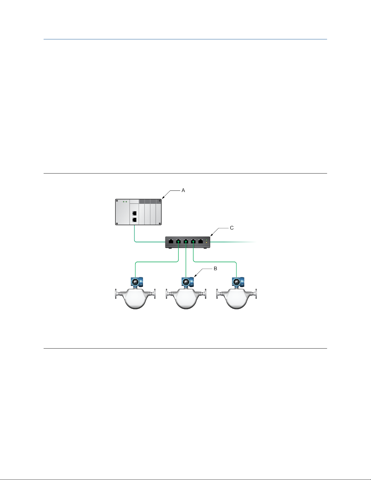
2.1 Star topology
5700 Ethernet transmitters can be installed in a star network.
Figure 2-1: 5700 star network
A. Programmable Logic Controller (PLC)
B. 5700 with Ethernet output
C. External Ethernet switch
EtherNet/IP Rockwell RSLogix Integration Guide 7
Page 8
5700 transmitters in Ethernet networks Integration Guide
March 2022 MMI-20029770
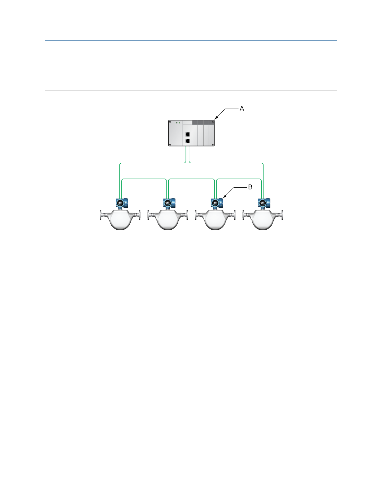
2.2 Ring topology
5700 Ethernet transmitters can be installed in a ring network.
Figure 2-2: 5700 ring network
A. Programmable Logic Controller (PLC)
B. 5700 with Ethernet output
8 Micro Motion 5700 EtherNet/IP transmitters
Page 9
Integration Guide 5700 transmitters in Ethernet networks
MMI-20029770 March 2022
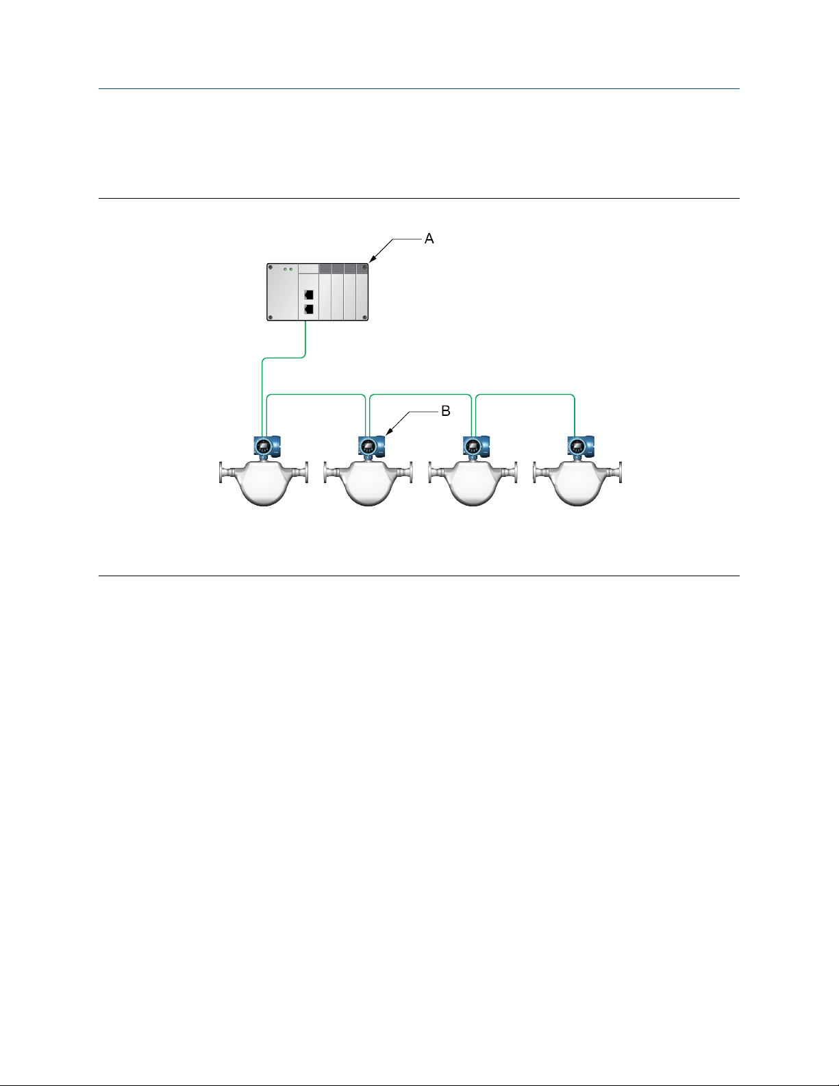
2.3 Daisy-chain topology
5700 Ethernet transmitters can be installed in a daisy-chain network.
Figure 2-3: 5700 daisy-chain network
A. Programmable Logic Controller (PLC)
B. 5700 with Ethernet output
EtherNet/IP Rockwell RSLogix Integration Guide 9
Page 10

5700 transmitters in Ethernet networks Integration Guide
March 2022 MMI-20029770
10 Micro Motion 5700 EtherNet/IP transmitters
Page 11
Integration Guide Integrate with RSLogix 5000
MMI-20029770 March 2022
3 Integrate with RSLogix 5000
3.1 Integrate with Rockwell RSLogix 5000 versions 20
and later
If you have Rockwell RSLogix 5000 version 20 or later firmware and programming software, use this section to
load the 5700 Electronic Data Sheet (EDS) and commission the device using the RSLogix 5000 programming
package.
Prerequisites
If you are upgrading the EDS from an older version, unregister the old EDS first using the RSLogix 5000 EDS
Hardware Installation Tool at Tools → EDS Hardware Installation Tool.
Procedure
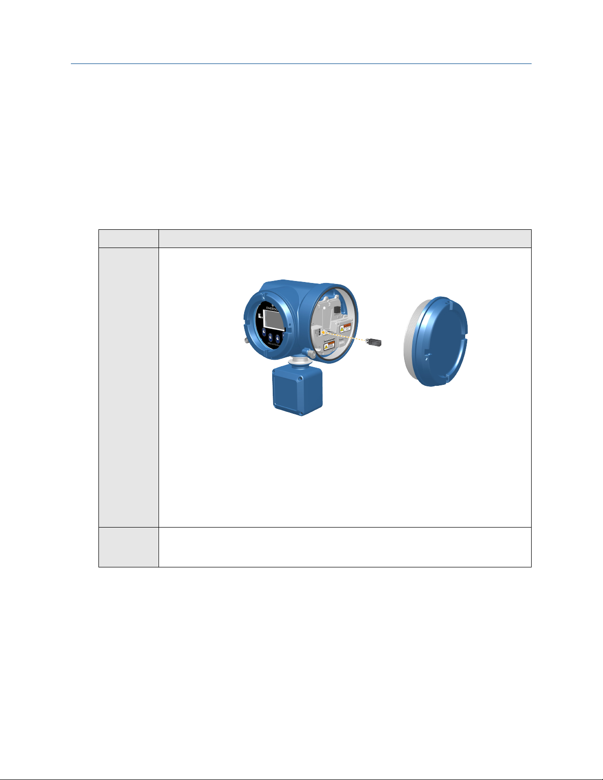
1. Download the EDS file using one of the following methods:
Option Description
Use a USB
memory
drive
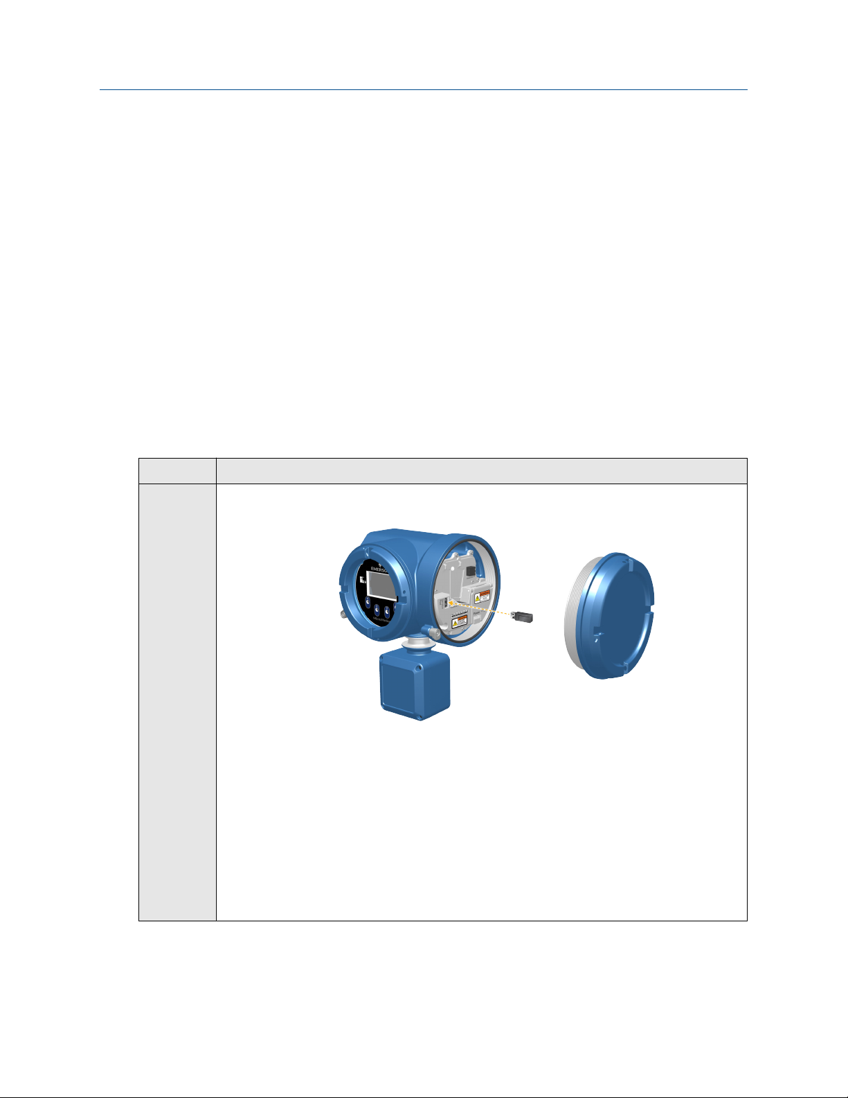
a. Insert a USB memory drive into the 5700 Ethernet service port.
The service port connection is located under the transmitter cap.
b. From the transmitter display, choose Menu → USB Options → Transmitter → USB
Drive → Download Support Files → EDS file.
c. Follow the menu to copy the EDS file to the memory drive.
d. Copy the zip file from the USB memory drive to the PC where RSLogix 5000 is
installed.
e. Unzip the file to a chosen location.
f. In RSLogix 5000, choose Tools → EDS Hardware Installation Tool and register the
5700 EDS file.
EtherNet/IP Rockwell RSLogix Integration Guide 11
Page 12
Integrate with RSLogix 5000 Integration Guide
March 2022 MMI-20029770
Option Description
Download
the file
a. Download the EDS from the Micro Motion 5700 Ethernet product website.
b. Unzip the file to a chosen location.
c. In RSLogix 5000, choose Tools → EDS Hardware Installation Tool and register the
5700 EDS file.
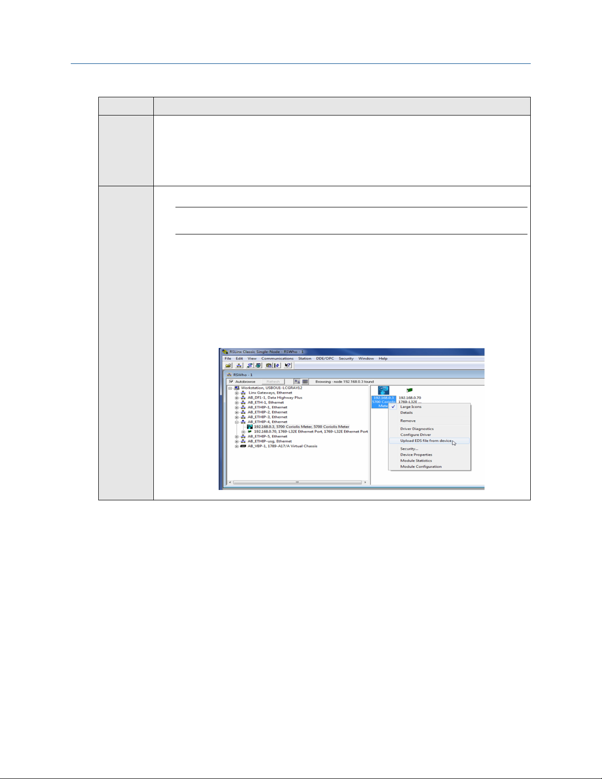
Use RSLinx a. Using RSLinx, start RSLinx Classic.
Note
The 5700 transmitter must be active on the EtherNet/IP network.
b. Choose Communications → RSWho.
c. Expand the appropriate network card in the left panel tree.
d. From the device pane, right-click 5700 Transmitter.
e. Choose Upload EDS File from Device.
f. Follow the prompts from the Rockwell Automation's EDS Wizard to register the
EDS.
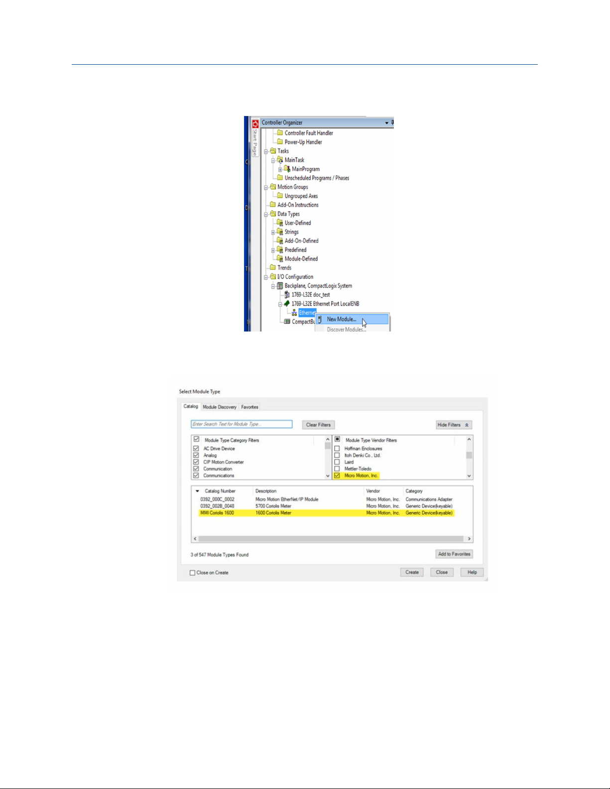
2. To add the 5700 Ethernet device to the RSLogix 5000 Ethernet network, right-click the Ethernet
network and select New Module…
12 Micro Motion 5700 EtherNet/IP transmitters
Page 13
Integration Guide Integrate with RSLogix 5000
MMI-20029770 March 2022
Example
a) Select the 5700 from the Select Module Type window and press Create.
Example
The New Module properties dialog is displayed. The EDS generates an Add On Profile (AOP) for
the 5700 that loads all the variables into the controller's input and output image tables as named
variables with the correct data types.
b) Enter the Name of the module.
c) Enter the IP Address.
EtherNet/IP Rockwell RSLogix Integration Guide 13
Page 14

Integrate with RSLogix 5000 Integration Guide
March 2022 MMI-20029770
3. Change or keep the current connection type.
Option Description
To change the connection type Go to Step 4.
To keep the current connection type Go to Step 5.
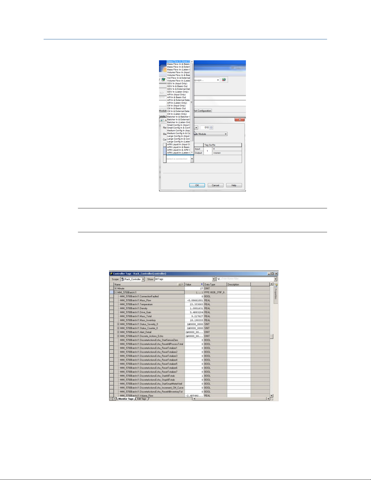
4. From the General tab, change the connection type:
a) Select the Change… button.
Example
b) Click the current connection.
Default = Mass Flow In & Basic
A pull-down menu with all the available connection types is displayed. For descriptions, see
Table B-2.
14 Micro Motion 5700 EtherNet/IP transmitters
Page 15
Integration Guide Integrate with RSLogix 5000
MMI-20029770 March 2022
c) Select your appropriate connection, and press OK.
Note
If you change the connection after the device goes online, you will need to take the controller
offline in order for the change to take effect.
5. On the New Module properties dialog, click OK.
6. On the Select Module Type dialog, click Close.
7. Open Controller Tags to verify the organization of data.
EtherNet/IP Rockwell RSLogix Integration Guide 15
Page 16
Integrate with RSLogix 5000 Integration Guide
March 2022 MMI-20029770
3.2 Integrate with Rockwell RSLogix 5000 versions 19
and earlier
Use this section if you have Rockwell RSLogix 5000 version 19 or earlier firmware and programming software.
These early versions do not support the transmitter Electronic Data Sheet (EDS)-generated Add On Profile
(AOP). Instead, you must use the generic module hardware tree.
Procedure
1. Download the EDS file using one of the following methods:
Option Description
Use a USB
memory
drive
Download
the file
a. Insert a USB memory drive into the 5700 Ethernet service port.
The service port connection is located under the transmitter cap.
b. From the transmitter display, choose Menu → USB Options → Transmitter → USB
Drive → Download Support Files → EDS file.
c. Follow the menu to copy the EDS file to the memory drive.
d. Copy the zip file from the USB memory drive to the PC where RSLogix 5000 is
installed.
e. Unzip the file to a chosen location.
a. Download the EDS from the Micro Motion 5700 Ethernet product website.
b. Unzip the file to a chosen location.
2. In RSLogix 5000, choose Tools → EDS Hardware Installation Tool and register the 5700 EDS file.
3. To add the 5700 Ethernet device to the RSLogix 5000 Ethernet network, right-click the Ethernet
network and select New Module....
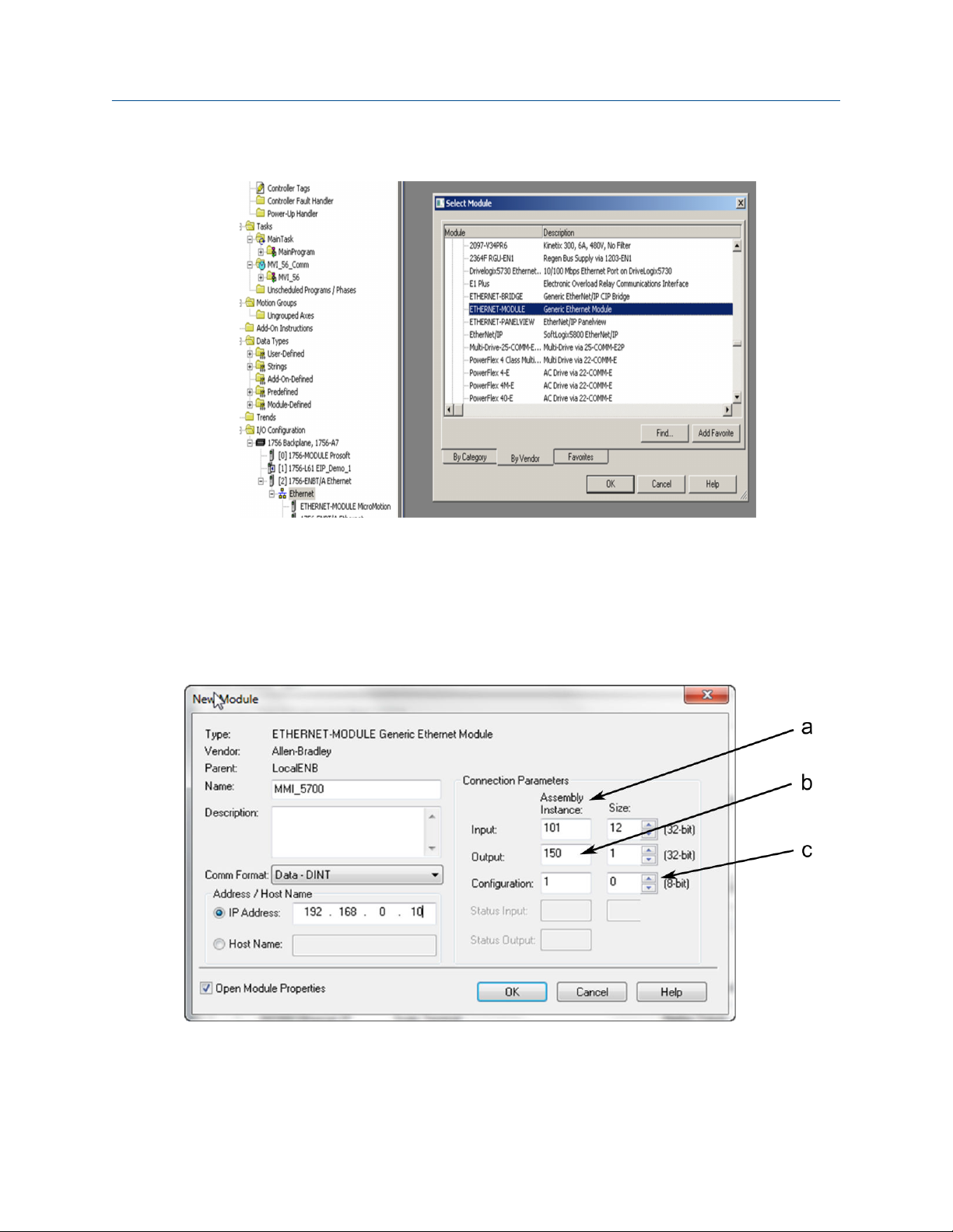
4. From the By Vendor tab, select ETHERNET-MODULE Generic Ethernet Module.
16 Micro Motion 5700 EtherNet/IP transmitters
Page 17
Integration Guide Integrate with RSLogix 5000
MMI-20029770 March 2022
Example
5. Select OK.
6. Select Data-DINT as the module data type.
7. Select the appropriate assembly instances for your application.
Enter the assembly numbers in the generic module setup, along with the data sizes that are listed in
Table B-1.
Example
a. Input = 101
b. Output = 150
c. Configuration = 1
EtherNet/IP Rockwell RSLogix Integration Guide 17
Page 18

Integrate with RSLogix 5000 Integration Guide
March 2022 MMI-20029770
Note
The 5700 does not use a Configuration instance. Enter 1 in the Assembly Instance column, and
0 length for the Size column.
8. Enter the IP Address of the transmitter.
9. Press OK.
10. Open Controller Tags to see the data organization.
11. Use your preferred programming techniques to convert the data from the input and output image
tables to the correct data types.
• The transmitter process variables are generally type REAL, use the COP command to convert them.
• The byte ordering is correct, so no byte swapping is needed.
18 Micro Motion 5700 EtherNet/IP transmitters
Page 19

Integration Guide Integrate with RSLogix 5000
MMI-20029770 March 2022
Example
EtherNet/IP Rockwell RSLogix Integration Guide 19
Page 20

Integrate with RSLogix 5000 Integration Guide
March 2022 MMI-20029770
20 Micro Motion 5700 EtherNet/IP transmitters
Page 21

Integration Guide Use explicit (messaging) using the Modbus Object
MMI-20029770 March 2022
4 Use explicit (messaging) using the Modbus Object
The programming for explicit variables is the same regardless of the controller firmware version. Explicit
messaging differs from implicit messaging in that the service code and class refer to a Modbus data type
rather than a specific data item. The message source element provides the location of the desired data in the
transmitter's database. The only difference is that the Common Industrial Protocol (CIP) message type refers
to a type of data in the transmitter's internal database rather than a specific data item. The desired data item
is referenced as the Modbus address in the CIP message. The data item does not have to be part of an
assembly, so in the example in Figure 4-1, a batcher data item is requested to be read.
For more information about CIP message codes, see Modbus object (44
Procedure
1. Create the Msg and select it.
2. Select the Source Element that was previously created as a controller scope tag.
Figure 4-1: Batch status message
Example
– 1 instance).
HEX
The following example shows a message that writes data to the transmitter database.
The Automatic Overshoot Compensation (AOC) value is a floating point number that you will need to
convert to integer format using a COP command prior to referencing it in the Source Element of the
message.
EtherNet/IP Rockwell RSLogix Integration Guide 21
Page 22

Use explicit (messaging) using the Modbus Object Integration Guide
March 2022 MMI-20029770
Combine the AOC value with the transmitter database (Modbus) address and length to form the
message's source element. This can be an array as shown in the following graphic or a user-defined
data type (UDT). The first element is the Modbus address (zero based), the second is the length, and
finally the data in integer (INT) format.
The address and data length will be returned if the write is successful. For example, Set_AOC_Rtn.
22 Micro Motion 5700 EtherNet/IP transmitters
Page 23

Integration Guide Use explicit (messaging) using the Modbus Object
MMI-20029770 March 2022
EtherNet/IP Rockwell RSLogix Integration Guide 23
Page 24

Use explicit (messaging) using the Modbus Object Integration Guide
March 2022 MMI-20029770
24 Micro Motion 5700 EtherNet/IP transmitters
Page 25

Integration Guide Use explicit (messaging) using the Analog Input Object
MMI-20029770 March 2022
5 Use explicit (messaging) using the Analog Input Object
As described in the previous chapter, explicit messaging using the Modbus object gives the programmer
access to all the data available in the transmitter database. A simpler method than using the Modbus object
to access process variable values, engineering units, and status, is to use the standard Common Industrial
Protocol (CIP) Analog Input object.
Related information
Analog Input Point object (0AHEX-51 instances)
5.1 Read mass flow value example
The following example shows a message that reads the mass flow value using the mass flow instance of the
Analog Input class.
Procedure
1. Create the Msg and select it.
2. Enter A in the Class field.
The A comes from the Analog Input object class 0xA.
3. Use Analog Input Point object (0A
a) Enter the appropriate instance in the Instance field as a hexadecimal number.
In this example, Mass Flow is Instance 1.
-51 instances) as a reference for the following steps:
HEX
b) Enter the appropriate attribute in the Attribute field as a hexadecimal number.
In this example, the value parameter is Attribute 3.
EtherNet/IP Rockwell RSLogix Integration Guide 25
Page 26

Use explicit (messaging) using the Analog Input Object Integration Guide
March 2022 MMI-20029770
5.2 Write mass flow example
The following example shows a message that writes the mass flow units using the mass flow instance of the
Analog Input class.
Procedure
1. Create the Msg and select it.
2. Enter A in the Class field.
The A comes from the Analog Input object class 0xA.
3. Use Analog Input Point object (0A
a) Enter the appropriate instance in the Instance field as a hexadecimal number.
In this example, Mass Flow is Instance 1.
b) Enter the appropriate attribute in the Attribute field as a hexadecimal number.
In this example, the engineering units parameter is Attribute 100 (64 Hex).
-51 instances) as a reference for the following steps:
HEX
26 Micro Motion 5700 EtherNet/IP transmitters
Page 27

Integration Guide Assembly object (04
MMI-20029770 March 2022
– 16 instances)
HEX
A Assembly object (04
HEX
– 16 instances)
A.1 Definitions
Abbreviation Definiition
USINT Unsigned short integer (8-bit)
UINT Unsigned integer (16-bit)
UDINT Unsigned double integer (32-bit)
SINT Signed integer (8-bit)
INT Signed integer (16-bit)
DINT Signed integer (32-bit)
SHORT STRINGNN Character string (1st byte is length; up to NN characters)
BYTE Bit string (8-bit)
WORD Bit string (16-bit)
DWORD Bit string (32-bit)
REAL IEEE 32-bit single precision floating point
A.2 Class attributes
Class attributes (instance 0)
Attribute ID
1 Revision UINT 2 Get
2 Max instance UINT 255 Get
Name Data type Data value Access rule
A.3 Input assemblies
Table A-1: Input instance attributes (Instances 100-112)
Attribute ID Name Data type Data value Access rule
3 Input data DWORD[varies] 0 Get
Table A-2: Common input data
Assembly
Dword
index
0 Mass Flow REAL
1 Temperature REAL
2 Density REAL
Name Data type
EtherNet/IP Rockwell RSLogix Integration Guide 27
Page 28

Assembly object (04
– 16 instances) Integration Guide
HEX
March 2022 MMI-20029770
Table A-2: Common input data (continued)
Assembly
Dword
index
3 Drive Gain REAL
4 Totalizer 1 (default = Mass Total) REAL
5 Inventory 1 (default = Mass Inventory) REAL
6 Status DWORD
Name Data type
Severity (bits 0-15) • Bit #0 = Immediate Failure
• Bit #1 = Last Measure Value Failure
• Bit #2 = Function Check
• Bit #3 = Out of Specification
• Bit #4 = Maintenance Required
Counter/Heartbeat (bits 16-32) The PLC will display the counter/
heartbeat as a signed INT, therefore
the counter can be negative.
28 Micro Motion 5700 EtherNet/IP transmitters
Page 29

Integration Guide Assembly object (04
– 16 instances)
HEX
MMI-20029770 March 2022
Table A-2: Common input data (continued)
Assembly
Dword
index
7 Alert detail • Bit #0 = Electronics Failure
Name Data type
• Bit #1 = Sensor Failed
• Bit #2 = Configuration Error
• Bit #3 = Core Low Power
• Bit #4 = Security Breach
• Bit #5 = Sensor-Transmitter
Communication Error
• Bit #6 = Tube Not Full
• Bit #7 = Extreme Primary Purpose
Variable
• Bit #8 = Reserved
• Bit #9 = Flowmeter Initializing
• Bit #10 = Function Check in
Progress
• Bit #11 = Sensor Being Simulated
• Bit #12 = Output Fixed
• Bit #13 = Drive Over Range
• Bit #14 = Process Aberration
• Bit #15 = Discrete Event X Active
• Bit #16 = Output Saturated
• Bit #17 = Function Check Failed
• Bit #18 = Data Loss Possible
DWORD
8 Echo Output Data Discrete Actions DWORD
Table A-3: Liquid volume flow
Assembly
Dword
index
0–8 Common input data See Table A-2
9 Volume Flow REAL
10 Totalizer 2 (default = Volume Total) REAL
11 Inventory 2 (default = Volume Inventory) REAL
EtherNet/IP Rockwell RSLogix Integration Guide 29
Name Data type
Page 30

Assembly object (04
– 16 instances) Integration Guide
HEX
March 2022 MMI-20029770
Table A-4: Gas volume flow
Assembly
Dword
index
0–8 Common input data See Table A-2
9 Gas Volume Flow REAL
10 Totalizer 4 (default = Gas Volume Total) REAL
11 Inventory 4 (default = Gas Volume Inventory) REAL
Name Data type
Table A-5: API referral
Assembly
Dword
index
0–8 Common input data See Table A-2
9 Volume Flow REAL
10 Totalizer 2 (default = Volume Total) REAL
11 Inventory 2 (default = Volume Inventory) REAL
12 Corrected Density REAL
13 Corrected Vol Flow REAL
14 Totalizer 3 (default = Corrected Vol Total) REAL
Name Data type
15 Inventory 3 (default = Corrected Vol Inv) REAL
16 Avg Density REAL
17 Avg Temperature REAL
18 CTL REAL
Table A-6: Concentration measurement
Assembly
Dword
index
0–8 Common input data See Table A-2
9 Volume Flow REAL
10 Totalizer 2 (default = Volume Total) REAL
11 Inventory 2 (default = Volume Inventory) REAL
12 Density at Reference REAL
13 Std Vol Flow Rate REAL
14 Totalizer 5 (default = Std Vol Total) REAL
15 Inventory 5 (default = Std Vol Inv) REAL
16 Net Mass Flow Rate REAL
Name Data type
30 Micro Motion 5700 EtherNet/IP transmitters
Page 31

Integration Guide Assembly object (04
– 16 instances)
HEX
MMI-20029770 March 2022
Table A-6: Concentration measurement (continued)
Assembly
Dword
index
17 Totalizer 6 (default = Net Mass Total) REAL
18 Inventory 6 (default = Net Mass Inv) REAL
19 Net Vol Flow Rate REAL
20 Totalizer 7 (default = Net Vol Flow Total) REAL
21 Inventory 7 (default = Net Vol Flow Inv) REAL
22 Concentration REAL
23 Density - Fixed SG Units REAL
24 Density - Special Density Units REAL
Table A-7: Batcher
Assembly
Dword
index
0–8 Common input data See Table A-3
9–11 Liquid Volume
12 Batch Total REAL
Name Data type
Name Data type
13 Overshoot Compensation Value (Reg 1457) REAL
14 Batch Fill Time REAL
EtherNet/IP Rockwell RSLogix Integration Guide 31
Page 32

Assembly object (04
– 16 instances) Integration Guide
HEX
March 2022 MMI-20029770
Table A-7: Batcher (continued)
Assembly
Dword
index
15 Fill status and diagnostics
Name Data type
• Bit #0 - Primary Fill in progress (reg 2495 bit 0)
• Bit #1 - Primary AOC training (reg 2495 bit 9)
• Bit #2 = Primary Valve (reg 2495 bit 5
• Bit #3 = Undefined
• Bit #4 = Undefined
• Bit #5 = Undefined
• Bit #6 - Fill Start Not Okay (reg 2496 bit 0)
• Bit #7 - AOC Flow Rate Too High (reg 2496 bit 1)
• Bit #8 - Maximum Fill Time Exceeded (reg 2496 bit 2)
• Bit #9 - Slug Flow (reg 2496 bit 3)
• Bit #10 - Tube Not Full (reg 2496 bit 4)
• Bit #11 - Drive Overrange (reg 2496 bit 5)
• Bit #12 - Critical Sensor Failure (reg 2496 bit 6)
• Bit #13 - Critical Transmitter Failure (reg 2496 bit 7)
• Bit #14 - Density Out of Limits (reg 2496 bit 8)
• Bit #15 - Temperature Out of Limits (reg 2496 bit 9)
• Bit #16 - Bit #31 for future expansion
DWORD
Table A-8: Small input configurable data set
Assembly
Dword
index
0–8 Common input data See Table A-2
9–16 8 configurable slots REAL *8
Name Data type
Table A-9: Medium input configurable data set
Assembly
Dword
index
0–8 Common input data See Table A-2
9–24 16 configurable slots REAL *16
32 Micro Motion 5700 EtherNet/IP transmitters
Name Data type
Page 33

Integration Guide Assembly object (04
– 16 instances)
HEX
MMI-20029770 March 2022
Table A-10: Large input configurable data set
Assembly
Dword
index
0–8 Common input data See Table A-2
9–40 32 configurable slots REAL *32
Name Data type
Table A-11: Advanced Phase Measurement (APM) – liquid
Assembly
Dword
index
0–8 Common input data See Table A-2
9 Volume Flow REAL
10 Totalizer 2 (default = Volume Total) REAL
11 Inventory 2 = (default = Volume Inventory) REAL
12 Gas Void Fraction REAL
13 Contract Total 1 REAL
14 Contract Total 2 REAL
15 Contract Total 3 REAL
16 Contract Total 4 REAL
Name Data type
17 Net Oil Flow @ Line REAL
18 Net Water Flow @ Line REAL
19 Watercut @ Line REAL
20 Net Oil Total @ Line REAL
21 Net Water Total @ Line REAL
22 Density Oil @ Line REAL
23 Net Oil Flow @ Ref REAL
24 Net Water Flow @ Ref REAL
25 Watercut @ Ref REAL
26 Net Oil Total @ Ref REAL
27 Net Water Total @ Ref REAL
Table A-12: Advanced Phase Measurement (APM) – gas volume
Assembly
Dword
index
0–8 Common input data See Table A-2
9 Gas Volume Flow REAL
Name Data type
EtherNet/IP Rockwell RSLogix Integration Guide 33
Page 34

Assembly object (04
– 16 instances) Integration Guide
HEX
March 2022 MMI-20029770
Table A-12: Advanced Phase Measurement (APM) – gas volume (continued)
Assembly
Dword
index
10 Totalizer 4 (default = Gas Volume Total) REAL
11 Inventory 4 = (default = Gas Volume Inventory) REAL
12 Contract Total 1 REAL
13 Contract Total 2 REAL
14 Contract Total 3 REAL
15 Contract Total 4 REAL
16 Total time mist detected DWORD
17 APM Status
18 Liquid Mass Flow Estimate REAL
19 Watercut @ Ref REAL
(1) Do not include the parenthesis in the label.
Name Data type
• Bit #0 – TMR Algorithm Active (reg 433 bit 12)
• Bit #1 – Bit #15 currently not defined
• Bit #16 – Bit #31 for future expansion
Table A-13: Wet Gas Measurement
(1)
DWORD
Assembly
Dword
index
0-8 Common input data See Table A-2
9 Gas Volume Flow REAL
10 Totalizer 4 (default = Gas Volume Total) REAL
11 Inventory 4 (default = Gas Volume Inventory) REAL
12 Gas Volume Fraction REAL
13 Totalizer 2 (default = Volume Total) REAL
14 Inventory 2 (default = Volume Inventory) REAL
15 Contract Total 1 REAL
16 Contract Total 2 REAL
17 Contract Total 3 REAL
18 Contract Total 4 REAL
Name Data type
34 Micro Motion 5700 EtherNet/IP transmitters
Page 35

Integration Guide Assembly object (04
– 16 instances)
HEX
MMI-20029770 March 2022
Table A-13: Wet Gas Measurement (continued)
Assembly
Dword
index
19 Total time mist detected DWORD
20 APM Status
21 Liquid Mass Flow Estimate REAL
22 Watercut @ Ref REAL
23 Gas Mass Flow (Reg 2008) REAL
24 Liquid Volume Flow (Reg 2261) REAL
25 Gas to Liquid Ratio (Reg 2255) REAL
26 Gas to Oil Ratio (Reg 2263) REAL
27 Net Oil Flow @ Ref REAL
28 Net Water Flow @ Ref REAL
29 Net Oil Total @ Ref REAL
30 Net Water Total @ Ref REAL
Name Data type
• Bit #0 – TMR Algorithm Active (reg 433 bit 12)
• Bit #1 – Bit #15 undefined
• Bit #16 – Bit #31 for future expansion
DWORD
Table A-14: Device Status
Assembly
Dword
index
0 Status & Diagnosis
1 LPO REAL
2 RPO REAL
3 Live Zero REAL
4 Tube Frequency REAL
5 Core Temperature REAL
6 Case Temperature REAL
7 Core In Volts REAL
Name Data type
• Bit #0 – Smart Meter Verification Running
• Bit #1 – Smart Meter Verification Passed
• Bit #2 – Smart Meter Verification Failed
• Bit #3 – Smart Meter Verification Aborted
• Bit #4 – Bit #31 for future expansion
DWORD
EtherNet/IP Rockwell RSLogix Integration Guide 35
Page 36

Assembly object (04
– 16 instances) Integration Guide
HEX
March 2022 MMI-20029770
Table A-14: Device Status (continued)
Assembly
Dword
index
8 Flow Verification Zero REAL
9 Result 1 (LPO Normalized Stiffness Reg 5782) REAL
10 Result 1 (RPO Normalized Stiffness Reg 5784) REAL
11 Result 3 – Future Use REAL
12 Result 4 – Future Use REAL
13 Result 5 – Future Use REAL
14 Result 6 – Future Use REAL
15 Data 1 – (Confidence Interval LPO Reg 6360) REAL
16 Data 2 – (Confidence Interval RPO Reg 6362) REAL
17 Data 3 – (LPO Std. Dev. Reg 6356) REAL
18 Data 4 – (RPO Std. Dev. Reg 6358) REAL
19 Data 5 – (LPO Meter Factor Reg 6371) REAL
20 Data 6 – (RPO Meter Factor Reg 6373) REAL
21 Data 7 – Future Use REAL
22 Data 8 – Future Use REAL
Name Data type
23 Data 9 – Future Use REAL
24 Smart Meter Verification Run Number (Reg 5826) UINT
25 Smart Meter Verification Progress (Reg 3020) UINT
26 Code 1 (Abort Code Reg 3002) UINT
27 Code 2 – Future Use UINT
28 Code 3 – Future Use UINT
36 Micro Motion 5700 EtherNet/IP transmitters
Page 37

Integration Guide Assembly object (04
– 16 instances)
HEX
MMI-20029770 March 2022
A.4 Output assemblies
Table A-15: Common output data — Discrete actions only
Note
Common output data is required for every output assembly in order to access 5700 functions. Depending on the
application, not all functions may be used.
Assembly
Dword
index
0 Discrete Actions:
Name Data type
• Bit #0 – Start Sensor Zero (trigger start with a 1, no abort)
• Bit #1 – Reset All Process Totals (same as setting bits 2-8)
• Bit #2 – Reset Totalizer 1 (Mass Total by default)
• Bit #3 – Reset Totalizer 2 (Volume Total by default)
• Bit #4 – Reset Totalizer 3 (PM Ref Vol Total by default)
• Bit #5 – Reset Totalizer 4 (GSV Total by default)
• Bit #6 – Reset Totalizer 5 (CM Ref Vol Total by default)
• Bit #7 – Reset Totalizer 6 (CM Net Mass Total by default)
• Bit #8 – Reset Totalizer 7 (CM Net Vol Total by default)
• Bit #9 – Start All Totals (trigger start with a 1)
• Bit #10 – Stop All Totals (trigger stop with a 1)
If both start and stop =1, then totals are stopped
• Bit #11 – Start Smart Meter Verification (Continue Measuring Mode
only)
Trigger start with a 1, no abort
• Bit #12 – Reset all Inventory Totals
• Bit #13 – Bit #31 for future expansion
DWORD
Table A-16: External process data
Assembly
Dword
index
0 Common output data See Table A-15
1 External Pressure REAL
2 External Temperature REAL
Name Data type
Table A-17: Batcher
Assembly
Dword
index
0 Common output data See Table A-15
EtherNet/IP Rockwell RSLogix Integration Guide 37
Name Data type
Page 38

Assembly object (04
– 16 instances) Integration Guide
HEX
March 2022 MMI-20029770
Table A-17: Batcher (continued)
Assembly
Dword
index
1 Batch Target REAL
2 Batcher Control – Discrete Actions
Name Data type
• Bit #0 – Reserved
• Bit #1 – Start Fill
• Bit #2 – End Fill
• Bit #3 – Pause Fill
• Bit #4 – Resume Fill
• Bit #5 – Reserved
• Bit #6 – Start Training
• Bit #7 – Save AOC Calibration
• Bit #8 – Reset Batch Total
• Bit #9 – Print Batch Ticket
• Bit #10 – Reset Preset 1 Inventory
• Bit #11 – Reset Preset 2 Inventory
• Bit #12 – Reset Preset 3 Inventory
• Bit #13 – Reset Preset 4 Inventory
• Bit #14 – Reset Preset 5 Inventory
• Bit #15 – Reset Preset 6 Inventory
• Bit #16 – Inhibit Totalizer
• Bit #17 – Inhibit Flow
• Bit #18 – Inhibit Batch
• Bit #19 – Bit #31 for future expansion
DWORD
3 Maximum Batch Time (Reg 1305) REAL
4 Batch Preset UINT
Table A-18: Batcher and external process data
Assembly
Dword
index
0–2 External process data See Table A-16
3 Batch Target REAL
38 Micro Motion 5700 EtherNet/IP transmitters
Name Data type
Page 39

Integration Guide Assembly object (04
– 16 instances)
HEX
MMI-20029770 March 2022
Table A-18: Batcher and external process data (continued)
Assembly
Dword
index
4 Batcher Control – Discrete Actions
Name Data type
• Bit #0 – Reserved
• Bit #1 – Start Fill
• Bit #2 – End Fill
• Bit #2 – Pause Fill
• Bit #4 – Resume Fill
• Bit #5 – Reserved
• Bit #6 – Start Training
• Bit #7 – Save AOC Calibration
• Bit #8 – Reset Batch Total
• Bit #9 – Print Batch Ticket
• Bit #10 – Reset Preset 1 Inventory
• Bit #11 – Reset Preset 2 Inventory
• Bit #12 – Reset Preset 3 Inventory
• Bit #13 – Reset Preset 4 Inventory
• Bit #14 – Reset Preset 5 Inventory
• Bit #15 – Reset Preset 6 Inventory
• Bit #16 – Inhibit Totalizer
• Bit #17 – Inhibit Flow
• Bit #18 – Inhibit Batch
• Bit #19 – Bit #31 for future expansion
DWORD
5 Maximum Batch Time (Reg 1305) REAL
6 Batch Preset UINT
Table A-19: Output configurable data
Assembly
Dword
index
0 Common output data See Table A-15
1 Configurable Slot 1 (Register) REAL
2 Configurable Slot 2 (Register) REAL
3 Configurable Slot 3 (Register) REAL
4 Configurable Slot 4 (Register) REAL
5 Configurable Slot 5 (Register) WORD
EtherNet/IP Rockwell RSLogix Integration Guide 39
Name Data type
Page 40

Assembly object (04
March 2022 MMI-20029770
– 16 instances) Integration Guide
HEX
Table A-19: Output configurable data (continued)
Assembly
Dword
index
6 Configurable Slot 6 (Register) WORD
7 Configurable Slot 7 (Register) WORD
8 Configurable Slot 8 (Register) WORD
9 Configurable Slot 9 (Coil) BOOL
10 Configurable Slot 10 (Coil) BOOL
11 Configurable Slot 11 (Coil) BOOL
12 Configurable Slot 12 (Coil) BOOL
Table A-20: Advanced Phase Measurement (APM)
Assembly
Dword
index
0 Common output data See Table A-15
1 External Pressure REAL
2 External Temperature REAL
3 External Water Cut REAL
Name Data type
Name Data type
A.5 Output Only Heartbeat (instance 253)
Use of this instance number in place of an input assembly instance number allows I/O connections to only
write data to the transmitter without any input data returned.
If not practical, remove this instance.
A.6 Input Only Heartbeat (instance 254)
Use of this instance number in place of an output assembly instance number allows I/O connections to
monitor the input data from the transmitter without providing any output data, called an “input only”
connection. Conceptually, input-only connections are used when HMIs or monitoring systems need to track
input data, while still allowing a Programmable Logic Controller (PLC) to provide the control side, or write the
outputs.
This connection type is required per the Recommended Functionality for EtherNet/IP Devices document.
For more information about Input Only connections, see Volume 1 of the ODVA Specification (Common
Industrial Protocol).
A.7 Listen Only Heartbeat (instance 255)
Much like Input Only connections, Listen Only connections use this instance number in place of an output
assembly instance number to open an I/O connection. The I/O connection monitors the input data from the
40 Micro Motion 5700 EtherNet/IP transmitters
Page 41

Integration Guide Assembly object (04
– 16 instances)
HEX
MMI-20029770 March 2022
transmitter. Existing I/O connections have dependencies for allocation and timeouts that are different than
Input Only connections.
A.8 Usage notes
All output assemblies contain a common data as outlined in assembly instance 150. To maintain proper
ownership of the output data (no toggling of outputs between multiple sources), only a single output
assembly may be selected for use in I/O messaging. To achieve this, there is an output lock in place to mark all
output assemblies as “owned” even though only a single assembly is actually in use.
All input instances can properly co-exist since no ownership is required. While not practical for most
applications, multiple PLCs can theoretically open Input Only connections to any or all of the input assembly
instances, up to the maximum number of I/O connections supported.
A.9 Common services
Service code
0E
HEX
10
HEX
Implemented for
Service name
Class level Instance level
Yes Yes Get_Attribute_Single
No Yes Set_Attribute_Single
EtherNet/IP Rockwell RSLogix Integration Guide 41
Page 42

Assembly object (04
– 16 instances) Integration Guide
HEX
March 2022 MMI-20029770
42 Micro Motion 5700 EtherNet/IP transmitters
Page 43

Integration Guide Assembly connections
MMI-20029770 March 2022
B Assembly connections
Table B-1: Input and output assemblies
Input assembly instance Size (32-bit) Output assembly instance Size (32-bit)
For definitions, see Input assemblies For definitions, see Output assemblies
100 – Basic Data 9 150 – Basic Data 1
101 – Liquid Volume 12 151 – External Process Data 3
102 – Gas Standard Volume 12 152 – Batcher 5
103 – API Referral 19 153 – Batcher and External Process Data 7
104 – Concentration Management 25 154 – Configurable Data Set 13
105 – Batcher 18 155 – APM External Process Data 4
106 – Small Configurable Data Set 17
107 – Medium Configurable Data Set 25 253 – Output Only Heartbeat 0
108 – Large Configurable Data Set 41 254 – Input Only Heartbeat 0
109 – APM – Liquid Volume 28 255 – Listen Only Heartbeat 0
110 – APM – Gas Volume 20
111 – Wet Gas Measurement 30
112 – Device Status 29
Table B-2: Connection types
ID Name Input assembly instance Output assembly instance
For definitions, see Input
assemblies
1 Mass Flow In & No Out 100 – Basic Data 254 – Input Only Heartbeat
2 Mass Flow In & Basic Out 100 – Basic Data 150 – Basic Data
3 Mass Flow In & External Data Out 100 – Basic Data 151 – External Process Data
4 Mass Flow In (Listen Only) 100 – Basic Data 255 – Listen Only Heartbeat
5 Volume Flow In & No Out 101 – Liquid Volume 254 – Input Only Heartbeat
6 Volume Flow In & Basic Out 101 – Liquid Volume 150 – Basic Data
7 Vol Flow In & External Data Out 101 – Liquid Volume 151 – External Process Data
8 Volume Flow In (Listen Only) 101 – Liquid Volume 255 – Listen Only Heartbeat
For definitions, see Output
assemblies
9 GSV In & No Out 102 – Gas Standard Volume 254 – Input Only Heartbeat
10 GSV In & Basic Out 102 – Gas Standard Volume 150 – Basic Data
11 GSV In & External Data Out 102 – Gas Standard Volume 151 – External Process Data
12 GSV In (Listen Only) 102 – Gas Standard Volume 255 – Listen Only Heartbeat
EtherNet/IP Rockwell RSLogix Integration Guide 43
Page 44

Assembly connections Integration Guide
March 2022 MMI-20029770
Table B-2: Connection types (continued)
ID Name Input assembly instance Output assembly instance
For definitions, see Input
assemblies
13 API In & No Out 103 – API Referral 254 – Input Only Heartbeat
14 API In & Basic Out 103 – API Referral 150 – Basic Data
15 API In & External Data Out 103 – API Referral 151 – External Process Data
16 API In (Listen Only) 103 – API Referral 255 – Listen Only Heartbeat
17 CM In & No Out 104 – Concentration Measurement 254 – Input Only Heartbeat
18 CM In & Basic Out 104 – Concentration Measurement 150 – Basic Data
19 CM In & External Data Out 104 – Concentration Measurement 151 – External Process Data
20 CM In (Listen Only) 104 – Concentration Measurement 255 – Listen Only Heartbeat
21 Batcher In & Batcher Out 105 – Batcher 152 – Batcher
22 Batcher In & External Data Out 105 – Batcher 153 – Batcher and External Data
23 Batcher In (Listen Only) 105 – Batcher 255 – Listen Only Heartbeat
24 Small Config In & No Out 106 – Small Configurable Data Set 254 – Input Only Heartbeat
25 Small Config In & Config Out 106 – Small Configurable Data Set 154 – Configurable Data Set
26 Medium Config In & No Out 107 – Medium Configurable Data
Set
27 Medium Config In & Config Out 107 – Medium Configurable Data
Set
For definitions, see Output
assemblies
254 – Input Only Heartbeat
154 – Configurable Data Set
28 Large Config In & No Out 108 – Large Configurable Data Set 254 – Input Only Heartbeat
29 Large Config In & Config Out 108 – Large Configurable Data Set 154 – Configurable Data Set
30 Large Config In (Listen Only) 108 – Large Configurable Data Set 255 – Listen Only Heartbeat
31 APM Liquid In & No Out 109 - APM Liquid 254 – Input Only Heartbeat
32 APM Liquid In & Basic Out 109 - APM Liquid 150 – Basic Data
33 APM Liquid In & APM Out 109 - APM Liquid 155 – APM External Process Data
34 APM Liquid In (Listen Only) 109 - APM Liquid 255 – Listen Only Heartbeat
35 APM Gas In & No Out 110 - APM Gas 254 – Input Only Heartbeat
36 APM Gas In & Basic Out 110 - APM Gas 150 – Basic Data
37 APM Gas In & APM Out 110 - APM Gas 155 – APM External Process Data
38 APM Gas In (Listen Only) 110 - APM Gas 255 – Listen Only Heartbeat
39 Wet Gas In & No Out 111 - Wet Gas 254 – Input Only Heartbeat
40 Wet Gas In & Basic Out 111 - Wet Gas 150 – Basic Data
41 Wet Gas In & APM Out 111 - Wet Gas 155 – APM External Process Data
42 Wet Gas In (Listen Only) 111 - Wet Gas 255 – Listen Only Heartbeat
44 Micro Motion 5700 EtherNet/IP transmitters
Page 45

Integration Guide Modbus object (44
MMI-20029770 March 2022
– 1 instance)
HEX
C Modbus object (44
The Modbus object provides a “pass through” to the internal Modbus representation of any data point. All
validation related to addressing, length, or write validation is handled by the Modbus DLL.
HEX
– 1 instance)
C.1 Modbus class attributes
Attribute ID Name Data type Data value Access rule
1 Revision UINT 3 Get
C.2 Instance attributes
No instance attributes are defined.
C.3 Common services
Service code Implemented for Service name
Class level Instance level
0E
4B
4C
4D
4E
4F
50
HEX
HEX
HEX
HEX
HEX
HEX
HEX
Yes Yes Get_Attribute_Single
No Yes Read_Discrete_Inputs
No Yes Read_Coils
No Yes Read_Input_Registers
No Yes Read_Holding_Registers
No Yes Write_Coils
No Yes Write_Holding_Registers
4B
Read_Discrete_Inputs (Modbus FC 0x02)
HEX
Table C-1: Request format
Name Data type Description Semantics
Starting address UINT Offset in table to begin
reading from
Quantity of inputs UINT Number of inputs to read 1-2000
Table C-2: Response format
Name Data type Description Semantics
Input status BYTE[n] Input values read 8 inputs are packed into
EtherNet/IP Rockwell RSLogix Integration Guide 45
Zero-based
each byte
Page 46

Modbus object (44
– 1 instance) Integration Guide
HEX
March 2022 MMI-20029770
4C
Read_Coils (Modbus FC 0x01)
HEX
Table C-3: Request format
Name Data type Description Semantics
Starting address UINT Offset in table to begin
reading from
Quantity of inputs UINT Number of coils to read 1-2000
Zero-based
Table C-4: Response format
Name Data type Description Semantics
Coil status BYTE[n] Input values read 8 coils are packed into each
byte
4D
Read_Input_Registers (Modbus FC 0x04)
HEX
Table C-5: Request format
Name Data type Description Semantics
Starting address UINT Offset in table to begin
reading from
Quantity of input registers UINT Number of input registers to
read
Zero-based
1-125
Table C-6: Response format
Name Data type Description Semantics
Input register values WORD[n] Input register values read Data swap to convert
between little endian (CIP)
and big endian (Modbus)
4E
Read_Holding_Registers (Modbus FC 0x03)
HEX
Table C-7: Request format
Name Data type Description Semantics
Starting address UINT Offset in table to begin
reading from
Quantity of input registers UINT Number of input registers to
read
Zero-based
1-125
Table C-8: Response format
Name Data type Description Semantics
Holding register values WORD[n] Holding register values read Data swap to convert
between little endian (CIP)
and big endian (Modbus)
46 Micro Motion 5700 EtherNet/IP transmitters
Page 47

Integration Guide Modbus object (44
– 1 instance)
HEX
MMI-20029770 March 2022
4F
Write_Coils (Modbus FC 0x0F)
HEX
Table C-9: Request format
Name Data type Description Semantics
Starting address UINT Offset in table to begin
writing to
Quantity of outputs UINT Number of output coils to
write
Output values BYTE[n] Output coils values
Zero-based
1-2000
Table C-10: Response format
Name Data type Description Semantics
Starting address UINT Offset in table where writing
began
Quantity of outputs UINT Number of output coils
written
50
Write_Holding_Registers (Modbus FC 0x10)
HEX
Zero-based
Table C-11: Request format
Name Data type Description Semantics
Starting address UINT Offset in table to begin
writing to
Quantity of outputs UINT Number of output coils to
write
Zero-based
1-125
Output values WORD[n] Output register values
Table C-12: Response format
Name Data type Description Semantics
Starting address UINT Offset in table where writing
began
Quantity of outputs UINT Number of output resisters
written
Zero-based
EtherNet/IP Rockwell RSLogix Integration Guide 47
Page 48

Modbus object (44
– 1 instance) Integration Guide
HEX
March 2022 MMI-20029770
48 Micro Motion 5700 EtherNet/IP transmitters
Page 49

Integration Guide Analog Input Point object (0A
MMI-20029770 March 2022
-51 instances)
HEX
D Analog Input Point object (0A
HEX
-51
instances)
Table D-1: Attributes
Attribute ID Name Notes
3 Value Data type = REAL
Read Only
4 Status 0 = Good
1 = Alarm State
Read Only
8 Value Data Type 1 = REAL
Read Only
100 Engineering Units Data type = UINT (see Engineering units for
codes)
Read/Write
Table D-2: Services
Service code Name
0x0E Get Attribute Single
0x10 Set Attribute Single
Table D-3: Instances
Instance in decimal Instance in hex Name
1 0x01 Mass Flow
2 0x02 Volume Flow
3 0x03 Density
4 0x04 Temperature
5 0x05 Gas Standard Volume Flow
6 0x06 Drive Gain (units = % only)
7 0x07 PM: Corrected Density
8 0x08 PM: Corrected Volume Flow
9 0x09 PM: Average Density
10 0x0A PM: Average Temperature
11 0x0B CM: Density at Reference
12 0x0C CM: Standard Volume Flow Rate
13 0x0D CM: Net Mass Flow Rate
14 0x0E CM: Net Volume Flow Rate
EtherNet/IP Rockwell RSLogix Integration Guide 49
Page 50

Analog Input Point object (0A
-51 instances) Integration Guide
HEX
March 2022 MMI-20029770
Table D-3: Instances (continued)
Instance in decimal Instance in hex Name
15 0x0F CM: Concentration
16 0x10 BATCHER: Batch Total
17 0x11 Totalizer 1
18 0x12 Totalizer 2
19 0x13 Totalizer 3
20 0x14 Totalizer 4
21 0x15 Totalizer 5
22 0x16 Totalizer 6
23 0x17 Totalizer 7
24 0x18 Inventory 1
25 0x19 Inventory 2
26 0x1A Inventory 3
27 0x1B Inventory 4
28 0x1C Inventory 5
29 0x1D Inventory 6
30 0x1E Inventory 7
31 0x1F APM: Gas Void Fraction (units = % only)
32 0x20 APM: Contract Total 1
33 0x21 APM: Contract Total 2
34 0x22 APM: Contract Total 3
35 0x23 APM: Contract Total 4
36 0x24 APM: Net Oil Flow @ Line
37 0x25 APM: Net Water Flow @ Line
38 0x26 APM: Water Cut @ Line
39 0x27 APM: Net Oil Total @ Line
40 0x28 APM: Net Water Total @ Line
41 0x29 APM: Density Oil @ Line
42 0x2A APM: Net Oil Flow @ Reference
43 0x2B APM: Net Water Flow @ Reference
44 0x2C APM: Water Cut @ Reference
45 0x2D APM: Net Oil Total @ Reference
46 0x2E APM: Net Water Total @ Reference
47 0x2F External Temperature
50 Micro Motion 5700 EtherNet/IP transmitters
Page 51

Integration Guide Analog Input Point object (0A
-51 instances)
HEX
MMI-20029770 March 2022
Table D-3: Instances (continued)
Instance in decimal Instance in hex Name
48 0x30 External Pressure
49 0x31 External Water Cut (units = % only)
50 0x32 APM: Unremediated Mass Flow
51 0x33 APM: Unremediated Volume Flow
Engineering units
Table D-4: General
Name Value in hex
Special Units 0x080F
percent 0x1007
Table D-5: Mass Flow
Name Value in hex
grams per second 0x1437
grams per minute 0x140F
grams per hour 0x1436
kilograms per second 0x1404
kilograms per minute 0x1445
kilograms per hour 0x1410
kilograms per day 0x1444
metric tons per minute 0x1463
metric tons per hour 0x1462
metric tons per day 0x1461
pounds per second 0x140B
pounds per minute 0x140C
pounds per hour 0x140D
pounds per day 0x145C
short tons per minute 0x1482
short tons per hour 0x1481
short tons per day 0x1480
long tons per hour 0x1475
long tons per day 0x1474
EtherNet/IP Rockwell RSLogix Integration Guide 51
Page 52

Analog Input Point object (0A
-51 instances) Integration Guide
HEX
March 2022 MMI-20029770
Table D-6: Mass
Name Value in hex
grams 0x2501
kilograms 0x2500
metric tons 0x2503
pounds 0x2505
short tons 0x2506
long tons 0x2507
Table D-7: Liquid Volume Flow
Name Value in hex
liters per second 0x1406
liters per minute 0x1413
liters per hour 0x1414
million liters per day 0x0802
cubic feet per second 0x1467
cubic feet per minute 0x1402
cubic feet per hour 0x1466
cubic feet per day 0x1465
cubic meters per second 0x0803
cubic meters per minute 0x1433
cubic meters per hour 0x1432
cubic meters per day 0x1431
gallons per second 0x1408
gallons per minute 0x1409
gallons per hour 0x140A
gallons per day 0x1434
million gallons per day 0x1447
imperial gallons per second 0x1443
imperial gallons per minute 0x1442
imperial gallons per hour 0x1441
imperial gallons per day 0x1440
barrels per second 0x1420
barrels per minute 0x141F
barrels per hour 0x141E
barrels per day 0x141D
52 Micro Motion 5700 EtherNet/IP transmitters
Page 53

Integration Guide Analog Input Point object (0A
-51 instances)
HEX
MMI-20029770 March 2022
Table D-7: Liquid Volume Flow (continued)
Name Value in hex
beer barrels per second 0x141C
beer barrels per minute 0x141B
beer barrels per hour 0x141A
beer barrels per day 0x1419
Table D-8: Liquid Volume
Name Value in hex
liters 0x2E02
cubic feet 0x2E06
cubic meters 0x2E01
gallons 0x2E08
imperial gallons 0x2E15
barrels 0x2E0C
beer barrels 0x2E0E
Table D-9: Gas Volume Flow
Name Value in hex
normal liter per second 0x1457
normal liter per minute 0x1456
normal liter per hour 0x1455
normal liter per day 0x1454
standard liter per second 0x080C
standard liter per minute 0x1401
standard liter per hour 0x080B
standard liter per day 0x080A
normal cubic meter per second 0x1453
normal cubic meter per minute 0x1452
normal cubic meter per hour 0x1451
normal cubic meter per day 0x1450
standard cubic meter per second 0x1460
standard cubic meter per minute 0x145F
standard cubic meter per hour 0x145E
standard cubic meter per day 0x145D
standard cubic feet per second 0x146C
EtherNet/IP Rockwell RSLogix Integration Guide 53
Page 54

Analog Input Point object (0A
-51 instances) Integration Guide
HEX
March 2022 MMI-20029770
Table D-9: Gas Volume Flow (continued)
Name Value in hex
standard cubic feet per minute 0x146D
standard cubic feet per hour 0x146E
standard cubic feet per day 0x146F
Table D-10: Gas Volume
Name Value in hex
normal liter 0x2E19
standard liter 0x0813
normal cubic meter 0x2E22
standard cubic meter 0x2E1A
standard cubic feet 0x2E1E
Table D-11: Density
Name Value in hex
specific gravity units 0x0804
grams per cubic centimeter 0x2F08
grams per liter 0x2F0F
grams per milliliter 0x2f0E
kilograms per cubic meter 0x2F07
kilograms per liter 0x2F10
pounds per gallon 0x2F0B
pounds per cubic foot 0x2F0C
pounds per cubic inch 0x2F0D
short tons per cubic yard 0x0807
degrees API 0x3000
Table D-12: Temperature
Name Value in hex
Degrees Celsius 0x1200
Degrees Fahrenheit 0x1201
Kelvin 0x1202
Degrees Rankine 0x1203
54 Micro Motion 5700 EtherNet/IP transmitters
Page 55

Integration Guide Analog Input Point object (0A
-51 instances)
HEX
MMI-20029770 March 2022
Table D-13: Pressure
Name Value in hex
inches of Water at 60 degF 0x0809
inches of Water at 68 degF 0x0800
inches of Water at 4 degC 0x080D
feet of water at 68 degF 0x1311
millimeters of Water at 68 degF 0x130F
inches of Mercury at 0 degC 0x1304
millimeters of Mercury at 0 degC 0x1303
millimeters of Water at 4 degC 0x080E
psi 0x1300
bar 0x1307
millibar 0x1308
pascal 0x1309
kilopascal 0x130A
megapascals 0x1312
atmosphere 0x130B
torr 0x1301
gram per square centimeter 0x130C
kilogram per square centimeter 0x1314
Table D-14: Concentration
Name Value in hex
Degrees Twaddell 0x0810
Degrees Balling 0x320A
Degrees Brix 0x320D
Degrees Baume (heavy) 0x320B
Degrees Baume (light) 0x320C
% solids per weight (% mass) 0x2F2F
% solids per volume (% volume) 0x2F2C
Proof per volume 0x0811
Proof per mass 0x0812
Percent Plato 0x320E
Related information
Use explicit (messaging) using the Analog Input Object
EtherNet/IP Rockwell RSLogix Integration Guide 55
Page 56

*MMI-20029770*
MMI-20029770
Rev. AE
2022
For more information:
©
2022 Micro Motion, Inc. All rights reserved.
The Emerson logo is a trademark and service mark of Emerson
Electric Co. Micro Motion, ELITE, ProLink, MVD and MVD Direct
Connect marks are marks of one of the Emerson Automation
Solutions family of companies. All other marks are property of
their respective owners.
www.emerson.com
Loading...