

Installation Manual: Net Oil Computer Software and NOC System | Micro Motion
Table of contents
 Loading...
Micro Motion Installation Manual: Net Oil Computer Software and NOC System | Micro Motion Manuals & Guides

Instruction Manual
P/N 20006437, Rev. A
Ma
y 2007
Micro Motion®
Net Oil Computer Software
and NOC system
Installation Manual

©2007, Micro Motion, Inc. All rights reserved. ELITE and ProLink are registered trademarks, and MVD and MVD Direct Connect
are trademarks of Micro Motion, Inc., Boulder, Colorado. Micro Motion is a registered trade name of Micro Motion, Inc., Boulder,
Colorado. The Micro Motion and Emerson logos are trademarks and service marks of Emerson Electric Co. All other trademarks
are property of their respective owners.

Contents
Chapter 1 Before You Begin . . . . . . . . . . . . . . . . . . . . . . . . . . . . . . . . . . . . . 1
1.1 Overview . . . . . . . . . . . . . . . . . . . . . . . . . . . . . . . . . . . . . . . . . . . . . . . . . . . . . . . . . . . 1
1.2 Responsibilities of the purchaser, designer, systems integrator, and installer . . . . . . 1
1.3 Safety . . . . . . . . . . . . . . . . . . . . . . . . . . . . . . . . . . . . . . . . . . . . . . . . . . . . . . . . . . . . . 1
1.4 About the Net Oil Computer Software. . . . . . . . . . . . . . . . . . . . . . . . . . . . . . . . . . . . . 1
1.5 Installation components and resources. . . . . . . . . . . . . . . . . . . . . . . . . . . . . . . . . . . . 2
1.6 Installation procedure . . . . . . . . . . . . . . . . . . . . . . . . . . . . . . . . . . . . . . . . . . . . . . . . . 3
1.7 Customer service . . . . . . . . . . . . . . . . . . . . . . . . . . . . . . . . . . . . . . . . . . . . . . . . . . . . 4
Chapter 2 NOC System Options and Installation Considerations . . . . . . . . . . . . 5
2.1 Overview . . . . . . . . . . . . . . . . . . . . . . . . . . . . . . . . . . . . . . . . . . . . . . . . . . . . . . . . . . . 5
2.2 NOC system design options . . . . . . . . . . . . . . . . . . . . . . . . . . . . . . . . . . . . . . . . . . . . 6
2.3 Micro Motion sensor interface . . . . . . . . . . . . . . . . . . . . . . . . . . . . . . . . . . . . . . . . . . . 7
2.4 Cable types . . . . . . . . . . . . . . . . . . . . . . . . . . . . . . . . . . . . . . . . . . . . . . . . . . . . . . . . . 8
2.5 ROC809 modules . . . . . . . . . . . . . . . . . . . . . . . . . . . . . . . . . . . . . . . . . . . . . . . . . . . . 8
2.6 Power requirements . . . . . . . . . . . . . . . . . . . . . . . . . . . . . . . . . . . . . . . . . . . . . . . . . . 9
2.7 Component location . . . . . . . . . . . . . . . . . . . . . . . . . . . . . . . . . . . . . . . . . . . . . . . . . 10
2.8 Hazardous area classifications . . . . . . . . . . . . . . . . . . . . . . . . . . . . . . . . . . . . . . . . . 10
2.9 I.S. requirements . . . . . . . . . . . . . . . . . . . . . . . . . . . . . . . . . . . . . . . . . . . . . . . . . . . . 11
2.10 Environmental requirements . . . . . . . . . . . . . . . . . . . . . . . . . . . . . . . . . . . . . . . . . . . 11
2.11 Grounding requirements . . . . . . . . . . . . . . . . . . . . . . . . . . . . . . . . . . . . . . . . . . . . . . 11
Chapter 3 Micro Motion Hardware Installation . . . . . . . . . . . . . . . . . . . . . . . 13
3.1 Overview . . . . . . . . . . . . . . . . . . . . . . . . . . . . . . . . . . . . . . . . . . . . . . . . . . . . . . . . . . 13
3.2 Installing the Micro Motion sensor. . . . . . . . . . . . . . . . . . . . . . . . . . . . . . . . . . . . . . . 13
3.3 Mounting the MVD Direct Connect I.S. barrier(s) . . . . . . . . . . . . . . . . . . . . . . . . . . . 14
3.4 Installing sensor wiring . . . . . . . . . . . . . . . . . . . . . . . . . . . . . . . . . . . . . . . . . . . . . . . 14
3.5 Installing power wiring to the I.S. barrier(s). . . . . . . . . . . . . . . . . . . . . . . . . . . . . . . . 20
Chapter 4 Software Installation and Setup . . . . . . . . . . . . . . . . . . . . . . . . . . 21
4.1 Overview . . . . . . . . . . . . . . . . . . . . . . . . . . . . . . . . . . . . . . . . . . . . . . . . . . . . . . . . . . 21
4.2 Installing and using ProLink II . . . . . . . . . . . . . . . . . . . . . . . . . . . . . . . . . . . . . . . . . . 21
4.2.1 PC requirements . . . . . . . . . . . . . . . . . . . . . . . . . . . . . . . . . . . . . . . . . . . 22
4.2.2 Installation kits . . . . . . . . . . . . . . . . . . . . . . . . . . . . . . . . . . . . . . . . . . . . . 22
4.2.3 Installation and setup . . . . . . . . . . . . . . . . . . . . . . . . . . . . . . . . . . . . . . . . 22
4.2.4 Connecting with ProLink II . . . . . . . . . . . . . . . . . . . . . . . . . . . . . . . . . . . . 24
4.3 Installing and using ROCLINK 800 . . . . . . . . . . . . . . . . . . . . . . . . . . . . . . . . . . . . . . 25
4.3.1 PC requirements for ROCLINK 800 . . . . . . . . . . . . . . . . . . . . . . . . . . . . . 25
4.3.2 Installing ROCLINK 800. . . . . . . . . . . . . . . . . . . . . . . . . . . . . . . . . . . . . . 25
4.3.3 Starting ROCLINK 800 . . . . . . . . . . . . . . . . . . . . . . . . . . . . . . . . . . . . . . 26
4.3.4 Connecting from ROCLINK 800 to the ROC809 platform . . . . . . . . . . . . 26
4.4 Installing the license key with the NOC license. . . . . . . . . . . . . . . . . . . . . . . . . . . . . 26
4.5 Installing the Net Oil Computer Software . . . . . . . . . . . . . . . . . . . . . . . . . . . . . . . . . 27
4.6 Downloading the startup configuration file . . . . . . . . . . . . . . . . . . . . . . . . . . . . . . . . 28
Installation Manual i

Contents
Chapter 5 Startup Procedures. . . . . . . . . . . . . . . . . . . . . . . . . . . . . . . . . . . 31
5.1 Overview . . . . . . . . . . . . . . . . . . . . . . . . . . . . . . . . . . . . . . . . . . . . . . . . . . . . . . . . . . 31
5.2 Core processor configuration . . . . . . . . . . . . . . . . . . . . . . . . . . . . . . . . . . . . . . . . . . 31
5.3 Sensor zero. . . . . . . . . . . . . . . . . . . . . . . . . . . . . . . . . . . . . . . . . . . . . . . . . . . . . . . . 32
5.3.1 Preparing for zero . . . . . . . . . . . . . . . . . . . . . . . . . . . . . . . . . . . . . . . . . . 33
5.3.2 Zero procedure . . . . . . . . . . . . . . . . . . . . . . . . . . . . . . . . . . . . . . . . . . . . 33
Index . . . . . . . . . . . . . . . . . . . . . . . . . . . . . . . . . . . . . . . . . . . . . . . . . . . . . 35
ii Micro Motion® Net Oil Computer Software and NOC System
Chapter 1
Before You Begin
1.1 Overview
®
This chapter provides an orientation to the Micro Motion
installation process.
1.2 Responsibilities of the purchaser, designer, systems integrator, and installer
The Net Oil Computer Software is one component in a net oil measurement system (NOC system).
The purchaser, designer, systems integrator, and installer are responsible for ensuring that the
complete system and installation meet all applicable environmental and safety requirements and
regulations.
1.3 Safety
Net Oil Computer Software and the
Installation Considerations Software InstallationHardware InstallationBefore You Begin
Safety messages are provided throughout this manual to protect personnel and equipment. Read each
safety message carefully before proceeding to the next step. Note that only safety messages applicable
to Micro Motion components and procedures are included in this manual. It is the user’s responsibility
to comply with safety requirements for other components and procedures.
Improper installation in a hazardous area can cause an explosion. When installing in a hazardous area,
refer to Micro Motion approvals instructions, shipped with the product or available from the Micro Motion
web site.
Improper installation can cause measurement error or system failure. Follow all instructions to ensure
that the system will operate correctly.
1.4 About the Net Oil Computer Software
The Net Oil Computer Software is a user program designed to run on the ROC809 Remote Operations
Controller from Remote Automation Solutions. The Net Oil Computer Software performs net oil
measurements and calculations and provides a variety of real-time, average, summary, and historical
net oil data.
The Net Oil Computer Software requires input from at least one Micro Motion sensor, and may
optionally accept input from up to three Micro Motion sensors used for oil or water measurement, and
other devices used for gas measurement, pressure data, or temperature data.
Installation Manual 1

Before You Begin
1.5 Installation components and resources
Before beginning installation, ensure that you have all components and resources required for your
specific installation, as listed in Table 1-1.
Tabl e 1-1 Components and resources
Vendor Item Comments
Micro Motion Micro Motion sensor(s) One or more required
MVD™ Direct Connect™ I.S. barrier(s) One required for each Micro Motion sensor
Sensor installation manual Shipped with sensor
Available on Micro Motion web site
Approvals documentation Shipped with sensor
Available on Micro Motion web site
Net Oil Computer Software Required
Shipped with NOC order
License key with NOC license Required
Shipped with NOC order
ROCLINK
™
800 software from Micro Motion
NOCStartup_CONTINUOUS.800
NOCStartup_WELLTEST.800
LOI cable Required
Micro Motion Net Oil Computer Software and
NOC System: Configuration and Use Manual
ProLink
™
II software, manual, and installation
kit
Xycom display drivers for Emerson and
sample program for Xycom display panel
Example parts list Optional
Remote Automation
Solutions
ROC809 Remote Operations Controller Required
RS-485 communications module Required for communication with
Other modules As required for specific installation
License key with AGA license Required for gas measurement
ROC809 Remote Operations Controller:
Instruction Manual
ROCLINK 800 Configuration Software: User
Manual
Third-party External measurement devices As required for specific installation
(1)
Required
Shipped with NOC order
Startup configuration files
Required
Shipped with NOC order
Shipped with NOC order
Required
Shipped with NOC order
Required
Shipped with NOC order
Optional
Shipped with NOC order
Shipped with NOC order
Micro Motion sensor
ROC809 installation instructions
Information on configuring, using, and
maintaining the ROC809 using
ROCLINK 800
(1) The ROCLINK 800 software shipped with the Net Oil Computer Software has been developed specifically for use with the Net Oil
Computer Software and the Model 3711 Gas Flow Computer from Micro Motion. Although you can use the standard version of
ROCLINK 800, Micro Motion recommends using the version supplied here.
2 Micro Motion® Net Oil Computer Software and NOC System

Before You Begin
1.6 Installation procedure
Adapt the following installation procedure for your specific installation and requirements.
1. Review Chapter 2 to determine the components to be installed, component locations, and
applicable installation requirements.
2. For all components supplied by other vendors, review the installation instructions and ensure
that installation plans will meet all applicable requirements.
3. According to instructions from Remote Automation Solutions, as provided in the manual
entitled ROC809 Remote Operations Controller: Instruction Manual:
• Install the ROC809 controller.
• Install the RS-485 module in Slot 1 (see Figure 2-4).
• Install the license key containing the AGA license (if present).
• Install power wiring.
4. Follow the instructions in Chapter 3 to:
• Install the Micro Motion sensor(s)
• Mount the I.S. barrier(s)
• Install wiring between the sensor(s) and the ROC809 platform
5. Follow the instructions in Chapter 4 to:
Installation Considerations Software InstallationHardware InstallationBefore You Begin
• Install ProLink II on the PC that will be used for communication with the core
processor(s)
• Install ROCLINK 800 on the PC that will be used for communication with the ROC809
• Install the license key containing the NOC license
• Download the Net Oil Computer Software to the ROC809
• Download the appropriate startup configuration file to the ROC809
6. Follow the instructions in Chapter 5 to verify core processor configuration and perform sensor
zero procedures.
7. According to vendor instructions, install all optional measurement devices, such as pressure
sensors, temperature sensors, or water cut probes. For wiring between the device and the
ROC809 platform, refer to the I/O wiring instructions provided in the manual entitled ROC809
Remote Operations Controller: Instruction Manual.
8. (Optional) Calibrate analog and/or RTD inputs. Instructions are provided in the manual
entitled ROCLINK 800 Configuration Software: User Manual.
Installation Manual 3

Before You Begin
1.7 Customer service
The best source for customer service on your NOC system is the overall system supplier. Please
contact your system supplier first to ensure the fastest resolution. To contact Micro Motion for direct
support on the flowmeter components, phone the support center nearest you:
• In the U.S.A., phone
800-522-MASS (800-522-6277) (toll-free)
• In Canada and Latin America, phone +1 303-527-5200
•In Asia:
- In Japan, phone 3 5769-6803
- In other locations, phone +65 6777-8211 (Singapore)
•In Europe:
- In the U.K., phone 0870 240 1978 (toll-free)
- In other locations, phone +31 (0) 318 495 555 (The Netherlands)
Customers outside the U.S.A. can also email Micro Motion customer service at
International.MMISupport@EmersonProcess.com.
4 Micro Motion® Net Oil Computer Software and NOC System

Chapter 2
NOC System Options and Installation Considerations
2.1 Overview
This chapter provides information on a variety of topics that affect installation. The following topics
are discussed:
• NOC system design options – see Section 2.2
• Interface to the Micro Motion sensor – see Section 2.3
• Cable types – see Section 2.4
• ROC809 modules – see Section 2.5
• Component location – see Section 2.7
• Hazardous area classifications – see Section 2.8
• I.S. requirements – see Section 2.9
Installation Considerations Software InstallationHardware InstallationBefore You Begin
• Environmental requirements – see Section 2.10
• Power requirements – see Section 2.6
• Grounding requirements – see Section 2.11
Review the information in this chapter before beginning installation.
Installation Manual 5
NOC System Options and Installation Considerations
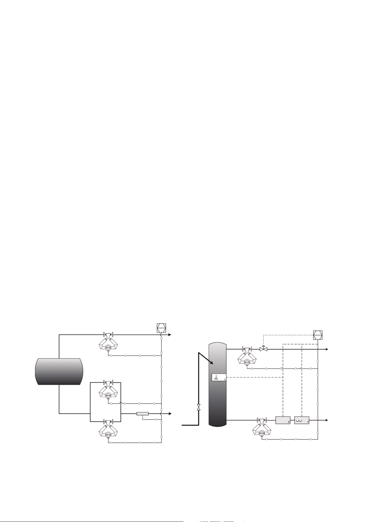
NOC system with two-phase separator NOC system with GLCC
NOC on ROC809
Gas leg
Liquid leg
Micro Motion sensors
Water cut probe
NOC on ROC809
Gas leg
Liquid leg
Micro Motion sensors
2.2 NOC system design options
Using the Net Oil Computer Software and the ROC809 controller, many different NOC systems can
be designed. The basic set of NOC system options is listed below:
• The NOC system may be used with a two-phase separator, including a variety of compact
separators (e.g., Gas-Liquid Cylindrical Cyclone, or GLCC
• A maximum of three Micro Motion sensors can be used for oil, water, or liquid (oil/water
mixture) measurement.
• On any one leg, up to three sensors can be installed in parallel.
• Gas measurement is optional. If a gas measurement device is installed, it may be a
Micro Motion sensor or a conventional device from another vendor. In either case, an AGA
license is required on the ROC809 platform.
• Pressure and temperature sensors are optional:
- If a pressure sensor is not installed, no pressure compensation or correction is applied to
sensor data or NOC measurement. If a pressure sensor is installed, either pressure
compensation, pressure correction, or both may be applied.
- If a temperature sensor is not installed, temperature data from the RTD on the
Micro Motion sensor will be used for temperature correction.
• Water cut probes (WCP) are optional. If a WCP is installed, it can be used for all water cut
measurement on the line, or used within a user-specified range.
• The ROC809 platform may be used to monitor and control other devices, such as a level
sensor. These functions are not managed by the Net Oil Computer Software. They must be set
up and configured separately.
The following figures illustrate several of these options.
Note: Although these illustrations show the ELITE
™
) or a three-phase separator.
®
sensor, other Micro Motion sensors can be used.
Figure 2-1 NOC systems with two-phase or GLCC separator
6 Micro Motion® Net Oil Computer Software and NOC System

NOC System Options and Installation Considerations
NOC on ROC809
Gas leg
Oil leg
Micro Motion sensors
Water cut probe
Water leg
NOC on ROC809
Gas leg
Oil leg
Water leg
Micro Motion sensors
ROC 809
I.S. barrier
Segment x
(4-wire cable)
Segment y
(4-wire cable)
Core processor
Figure 2-2 NOC systems with three-phase separators
Installation Considerations Software InstallationHardware InstallationBefore You Begin
2.3 Micro Motion sensor interface
The NOC system installation instructions assume that the core processor is installed integrally with
the sensor, as shown in Figure 2-3.
The MVD Direct Connect
™
I.S. barrier is required between the ROC809 platform and the core
processor. All I.S. barriers required for Micro Motion sensors are shipped with the system.
If multiple Micro Motion sensors are used, there is no requirement that the sensors be the same type
or same size.
Figure 2-3 Sensor interface to ROC809
Installation Manual 7

NOC System Options and Installation Considerations
2.4 Cable types
Micro Motion offers two types of 4-wire cable: shielded and armored. Both types contain shield drain
wires. The wires are color-coded as shown in Table 2-1.
Tabl e 2-1 Micro Motion 4-wire cable
Wire color Function Wire size
Red VDC + 18 AWG (0,75 mm2)
Black VDC –
White RS-485/A 22 AWG (0,35 mm2)
Green RS-485/B
User-supplied 4-wire cable must meet the following requirements:
• Twisted pair construction
• The following gauge requirements:
- RS-485 wires – 22 AWG (0,35 mm
- Power wires – 22–18 AWG (0,35–0,8 mm
• The applicable hazardous area requirements, if the sensor is installed in a hazardous area (see
the approval documents shipped with the sensor or available on the Micro Motion web site)
2
) or larger
2
)
2.5 ROC809 modules
To support the NOC system, the ROC809 controller must be ordered with an RS-485 module that is
used to communicate with the Micro Motion sensor(s). Other modules that may be part of the
NOC system include:
• Analog output module – typically used for liquid control valve, gas control valve
• Analog input module – typically used for WCP, pressure sensor, level sensor, gas sensor
• Discrete output module – typically used for pump or device control, alarm control, Transient
Bubble Remediation (TBR) implementation, frequency or pulse output simulation
• Discrete input module – typically used for external alarm indication
• RTD input module – typically used to provide external temperature data for temperature
correction
• RS-485 or RS-232 communications module – used for communications with host
These modules must be installed in the ROC809 module rack, which contains slots for nine modules.
The illustration in Figure 2-4 shows the required RS-485 sensor communications module in Slot 1,
and three optional modules.
Note: A variety of other modules are available for the ROC809, but are not used with a typical
NOC system.
8 Micro Motion® Net Oil Computer Software and NOC System
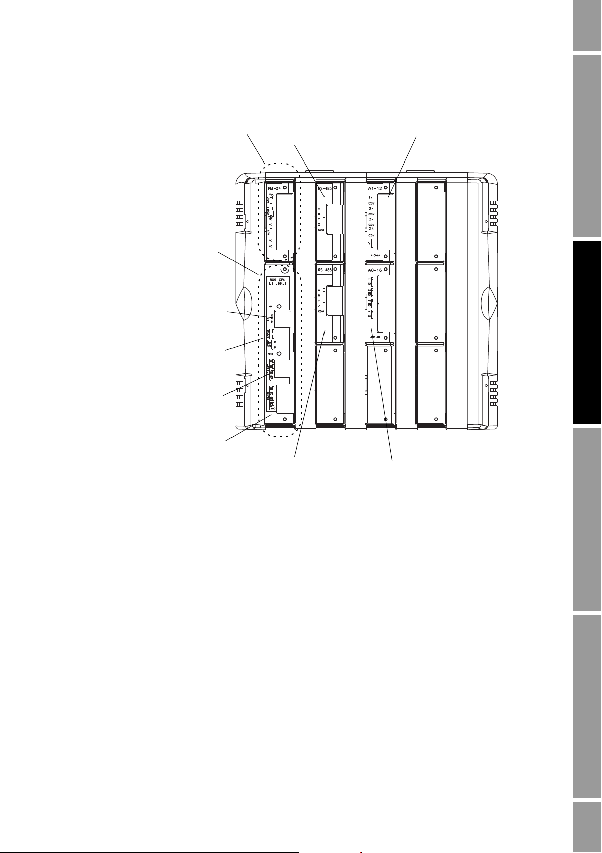
NOC System Options and Installation Considerations
Power input module
CPU module
Slot 1
RS-485 module for sensor
communications
COMM 2 (serial port)
on CPU module
COMM 1 (Ethernet port)
on CPU module
Local Operator Interface (LOI) port
on CPU module
Slot 4
Analog input module
Slot 2
RS-485 module for remote
communications
Slot 5
Analog output module
License keys
Figure 2-4 ROC809 module rack, modules, and module slots
Installation Considerations Software InstallationHardware InstallationBefore You Begin
2.6 Power requirements
There are two sets of power requirements:
• Requirements for the ROC809 platform – Total power requirements for the ROC809 platform
depend on the number and type of modules used, and the number of channels used per module.
See the document entitled ROC809 Remote Operations Controller: Instruction Manual to
calculate power requirements for your ROC809 platform.
• Requirements for the I.S. barrier(s) – Each I.S. barrier requires 24 VDC +/- 20% at the power
terminals. The I.S. barrier powers the core processor and sensor.
You can power the I.S. barriers separately or from the power input module on the ROC809 platform.
If you choose the second option, be sure to include the I.S. barrier requirements when you calculate
the ROC809 power requirements.
Installation Manual 9
Loading...