

Micro Motion Installation Manual: Micro Motion 5700 Transmitters with PROFIBUS-PA Manuals & Guides

Micro Motion™ 5700 Transmitters
Installation Manual for PROFIBUS® -PA
Installation Manual
MMI-20075112, Rev AA
August 2020

Safety messages
Safety messages are provided throughout this manual to protect personnel and equipment. Read each safety message carefully
before proceeding to the next step.
Safety and approval information
This Micro Motion product complies with all applicable European directives when properly installed in accordance with the
instructions in this manual. Refer to the EU declaration of conformity for directives that apply to this product. The EU declaration
of conformity, with all applicable European directives, and the complete ATEX Installation Drawings and Instructions are available
on the internet at www.emerson.com or through your local Micro Motion support center.
Information affixed to equipment that complies with the Pressure Equipment Directive, can be found on the internet at
www.emerson.com.
For hazardous installations in Europe, refer to standard EN 60079-14 if national standards do not apply.
Other information
Full product specifications can be found in the product data sheet. Troubleshooting information can be found in the configuration
manual. Product data sheets and manuals are available from the Micro Motion web site at www.emerson.com.
Return policy
Follow Micro Motion procedures when returning equipment. These procedures ensure legal compliance with government
transportation agencies and help provide a safe working environment for Micro Motion employees. Micro Motion will not accept
your returned equipment if you fail to follow Micro Motion procedures.
Return procedures and forms are available on our web support site at www.emerson.com, or by phoning the Micro Motion
Customer Service department.
Emerson Flow customer service
Email:
• Worldwide: flow.support@emerson.com
• Asia-Pacific: APflow.support@emerson.com
Telephone:
North and South America
United States 800-522-6277 U.K. and Ireland 0870 240 1978 Australia 800 158 727
Canada +1 303-527-5200 The Netherlands +31 (0) 70 413
Mexico +52 55 5809 5300 France +33 (0) 800 917
Argentina +54 11 4809 2700 Germany 0800 182 5347 Pakistan 888 550 2682
Brazil +55 15 3413 8000 Italy +39 8008 77334 China +86 21 2892 9000
Chile +56 2 2928 4800 Central & Eastern +41 (0) 41 7686
Peru +51 15190130 Russia/CIS +7 495 995 9559 South Korea +82 2 3438 4600
Europe and Middle East Asia Pacific
New Zealand 099 128 804
6666
India 800 440 1468
901
Japan +81 3 5769 6803
111
Egypt 0800 000 0015 Singapore +65 6 777 8211
Oman 800 70101 Thailand 001 800 441 6426
Qatar 431 0044 Malaysia 800 814 008
Kuwait 663 299 01
South Africa 800 991 390
Saudi Arabia 800 844 9564
UAE 800 0444 0684
2

Installation Manual Contents
MMI-20075112 August 2020
Contents
Chapter 1 Before you begin........................................................................................................5
1.1 About this document...................................................................................................................5
1.2 Hazard messages.........................................................................................................................5
1.3 Related documentation............................................................................................................... 6
Chapter 2 Planning.................................................................................................................... 7
2.1 Installation checklist.................................................................................................................... 7
2.2 Additional considerations for retrofitting existing installations.................................................... 8
2.3 Power requirements.................................................................................................................... 8
Chapter 3 Mounting and sensor wiring.................................................................................... 11
3.1 Mounting and sensor wiring for integral-mount transmitters.....................................................11
3.2 Mounting transmitters...............................................................................................................11
3.3 Wire a remote-mount transmitter to the sensor........................................................................ 15
3.4 Ground the meter components................................................................................................. 17
3.5 Rotate the transmitter on the sensor (optional)......................................................................... 18
3.6 Rotate the user interface on the transmitter (optional)..............................................................20
3.7 Rotate the sensor wiring junction box on a remote-mount transmitter (optional)......................21
Chapter 4 Wiring the channels................................................................................................. 23
4.1 Installation types for the 5700 transmitter.................................................................................23
4.2 Available channels..................................................................................................................... 23
4.3 Access the wiring channels........................................................................................................ 24
4.4 I/O wiring...................................................................................................................................25
4.5 FISCO-input entity parameters...................................................................................................26
4.6 Wiring for nonhazardous installations........................................................................................27
4.7 Wiring for hazardous installations..............................................................................................30
Chapter 5 Wiring the power supply..........................................................................................35
Chapter 6 Setting the 5700 for PROFIBUS-PA communication...................................................37
6.1 Addressing.................................................................................................................................37
Chapter 7 Power up the transmitter.........................................................................................39
Chapter 8 Guided setup............................................................................................................41
Chapter 9 Using the display controls........................................................................................ 43
Chapter 10 Available service port connection............................................................................. 45
Installation Manual 3

Contents Installation Manual
August 2020 MMI-20075112
4 Micro Motion 5700 transmitters for PROFIBUS PA

Installation Manual Before you begin
MMI-20075112 August 2020
1 Before you begin
1.1 About this document
This manual provides information on planning, mounting, wiring, and initial setup of the 5700 PROFIBUS-PA
transmitter. For information on full configuration, maintenance, troubleshooting, or service of the
transmitter, see the configuration and use manual.
The information in this document assumes that users understand basic transmitter and sensor installation,
configuration, and maintenance concepts and procedures.
1.2 Hazard messages
This document uses the following criteria for hazard messages based on ANSI standards Z535.6-2011
(R2017).
DANGER
Serious injury or death will occur if a hazardous situation is not avoided.
WARNING
Serious injury or death could occur if a hazardous situation is not avoided.
CAUTION
Minor or moderate injury will or could occur if a hazardous situation is not avoided.
NOTICE
Data loss, property damage, hardware damage, or software damage can occur if a situation is not avoided.
There is no credible risk of physical injury.
Physical access
NOTICE
Unauthorized personnel can potentially cause significant damage and/or misconfiguration of end users'
equipment. Protect against all intentional or unintentional unauthorized use.
Physical security is an important part of any security program and fundamental to protecting your system.
Restrict physical access to protect users' assets. This is true for all systems used within the facility.
Installation Manual 5

Before you begin Installation Manual
August 2020 MMI-20075112
1.3 Related documentation
You can find all product documentation on the product documentation DVD shipped with the product or at
www.emerson.com.
See any of the following documents for more information:
• Micro Motion 5700 Product Data Sheet
• Micro Motion 5700 Transmitters for PROFIBUS-PA: Configuration and Use Manual
• PROFIBUS-PA User and Installation Guideline
• Sensor installation manual
6 Micro Motion 5700 transmitters for PROFIBUS PA

Installation Manual
MMI-20075112 August 2020
Planning
2 Planning
2.1 Installation checklist
□ If possible, install the transmitter in a location that will prevent direct exposure to sunlight. The
environmental limits for the transmitter may be further restricted by hazardous area approvals.
□ If you plan to mount the transmitter in a hazardous area:
WARNING
— Verify that the transmitter has the appropriate hazardous area approval. Each transmitter has a
hazardous area approval tag attached to the transmitter housing.
— Ensure that any cable used between the transmitter and the sensor meets the hazardous area
requirements.
— For ATEX/IECEx installations, strictly adhere to the safety instructions documented in the ATEX/IECEx
approvals documentation available on the product documentation DVD shipped with the product or
at www.emerson.com.
□ Verify that you have the appropriate cable and required cable installation parts for your installation. For
wiring between the transmitter and sensor, verify the maximum cable length does not exceed 1,000 ft
(305 m).
□ Ensure that you use the following cables for the different connections:
— A certified PROFIBUS-PA cable for PROFIBUS-PA terminals
— A shielded, twisted-pair instrument cable with drain for all output connections
□ You can mount the transmitter in any orientation as long as the conduit openings or transmitter display do
not point upward.
Installing the transmitter with the conduit openings or transmitter display facing upward risks
condensation moisture entering the transmitter housing, which could damage the transmitter.
Following are examples of possible orientations for the transmitter.
Preferred orientation
Alternate orientations
□ Mount the meter in a location and orientation that satisfies the following conditions:
— Allows sufficient clearance to open the transmitter housing cover. Install with 8 in (203 mm) to 10 in
(254 mm) clearance at the wiring access points.
— Provides clear access for installing cabling to the transmitter.
— Provides clear access to all wiring terminals for troubleshooting.
Installation Manual 7

Planning
August 2020 MMI-20075112
Installation Manual
2.2 Additional considerations for retrofitting existing installations
□ The transmitter installation may require 3 in (76 mm) to 6 in (152 mm) of additional wiring for the input/
output and power connections. This length would be in addition to the currently installed wiring. Confirm
you have the additional wiring necessary for the new installation.
□ Before removing the existing transmitter, be sure to record the configuration data for the currently
installed transmitter. At initial startup of the newly installed transmitter, you will be prompted to
configure the meter via a guided setup.
Record the following information (if applicable):
Variable Setting
Tag
Mass flow units
Volume flow units
Density units
Temperature units
Calibration parameters (for 9-wire installations only)
Flow calibration factor FCF (Flow Cal or Flow Calibration Factor):
Density calibration factors — D1:
— D2:
— K1:
— K2:
— TC:
— FD:
Function block settings
Channel assignment
L_Type
XD_scale (engineering units
assignment)
Device address
Ident selection
2.3 Power requirements
Self-switching AC/DC input, automatically recognizes supply voltage:
• 85 to 240 VAC, 50/60 Hz, 6 watts typical, 11 watts maximum
• 18 to 100 VDC, 6 watts typical, 11 watts maximum
8 Micro Motion 5700 transmitters for PROFIBUS PA

Installation Manual Planning
MMI-20075112 August 2020
Note
For DC power:
• Power requirements assume a single transmitter per cable.
• At startup, the power source must provide a minimum of 1.5 amps of short-term current per transmitter
and not pull voltage below 18 VDC.
• Length and conductor diameter of the power cable must be sized to provide 18 VDC minimum at the
power terminals, at a load current of 0.7 amps.
Cable sizing formula
M = 18V + (R x L x 0.5A)
• M: minimum supply voltage
• R: cable resistance (in Ω/ft)
• L: cable length (in ft)
Typical power cable resistance at 68 °F (20.0 °C)
Wire gauge Resistance
14 AWG 0.0050 Ω/ft
16 AWG 0.0080 Ω/ft
18 AWG 0.0128 Ω/ft
20 AWG 0.0204 Ω/ft
2.5 mm
1.5 mm
1.0 mm
0.75 mm
0.50 mm
2
2
2
2
2
0.0136 Ω/m
0.0228 Ω/m
0.0340 Ω/m
0.0460 Ω/m
0.0680 Ω/m
2.3.1 Maximum cable lengths between sensor and transmitter
The maximum cable length between the sensor and transmitter that are separately installed is determined by
cable type.
Cable type
Micro Motion 4-wire remote mount Not applicable • 1,000 ft (305 m) without Ex-
Wire gauge Maximum length
approval
• 500 ft (152 m) with IIC rated
sensors
• 1,000 ft (305 m) with IIB rated
sensors
Micro Motion 9-wire remote mount Not applicable 60 ft (18 m)
User-supplied 4-wire VDC 22 AWG (0.326 mm²) 300 ft (91 m)
Installation Manual 9

Planning Installation Manual
August 2020 MMI-20075112
Cable type Wire gauge Maximum length
VDC 20 AWG (0.518 mm²) 500 ft (152 m)
VDC 18 AWG (0.823 mm²) 1,000 ft (305 m)
RS-485 22 AWG (0.326 mm²) or larger 1,000 ft (305 m)
10 Micro Motion 5700 transmitters for PROFIBUS PA
Installation Manual Mounting and sensor wiring
MMI-20075112 August 2020
3 Mounting and sensor wiring
3.1 Mounting and sensor wiring for integral-mount transmitters
There are no separate mounting requirements for integral transmitters, and no need to connect wiring
between the transmitter and the sensor.
3.2 Mounting transmitters
There are two options available for mounting transmitters:
• Mount the transmitter to a wall or flat surface.
• Mount the transmitter to an instrument pole.
3.2.1 Mounting the transmitter to a wall or flat surface
Prerequisites
• Micro Motion recommends 5/16-18 (8 mm–1.25) fasteners that can withstand the process environment.
Micro Motion does not supply bolts or nuts as part of the standard offering (general purpose bolts and
nuts are available as an option).
• Ensure that the surface is flat and rigid, does not vibrate, or move excessively.
• Confirm that you have the necessary tools, and the mounting kit shipped with the transmitter.
Procedure
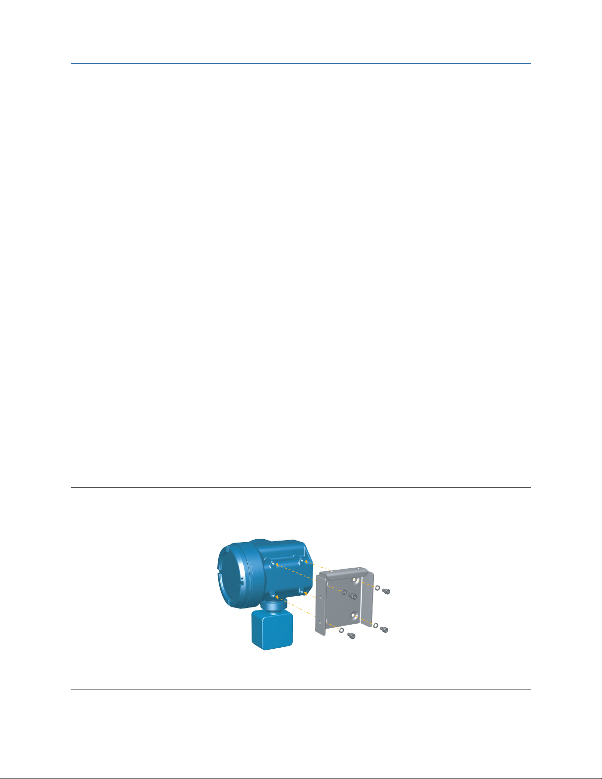
1. Attach the mounting bracket to the transmitter and tighten the screws to 80 in lbf (9.04 N m) to 90 in
lbf (10.17 N m).
Figure 3-1: Mounting bracket to an aluminum transmitter
Installation Manual 11
Mounting and sensor wiring Installation Manual
August 2020 MMI-20075112
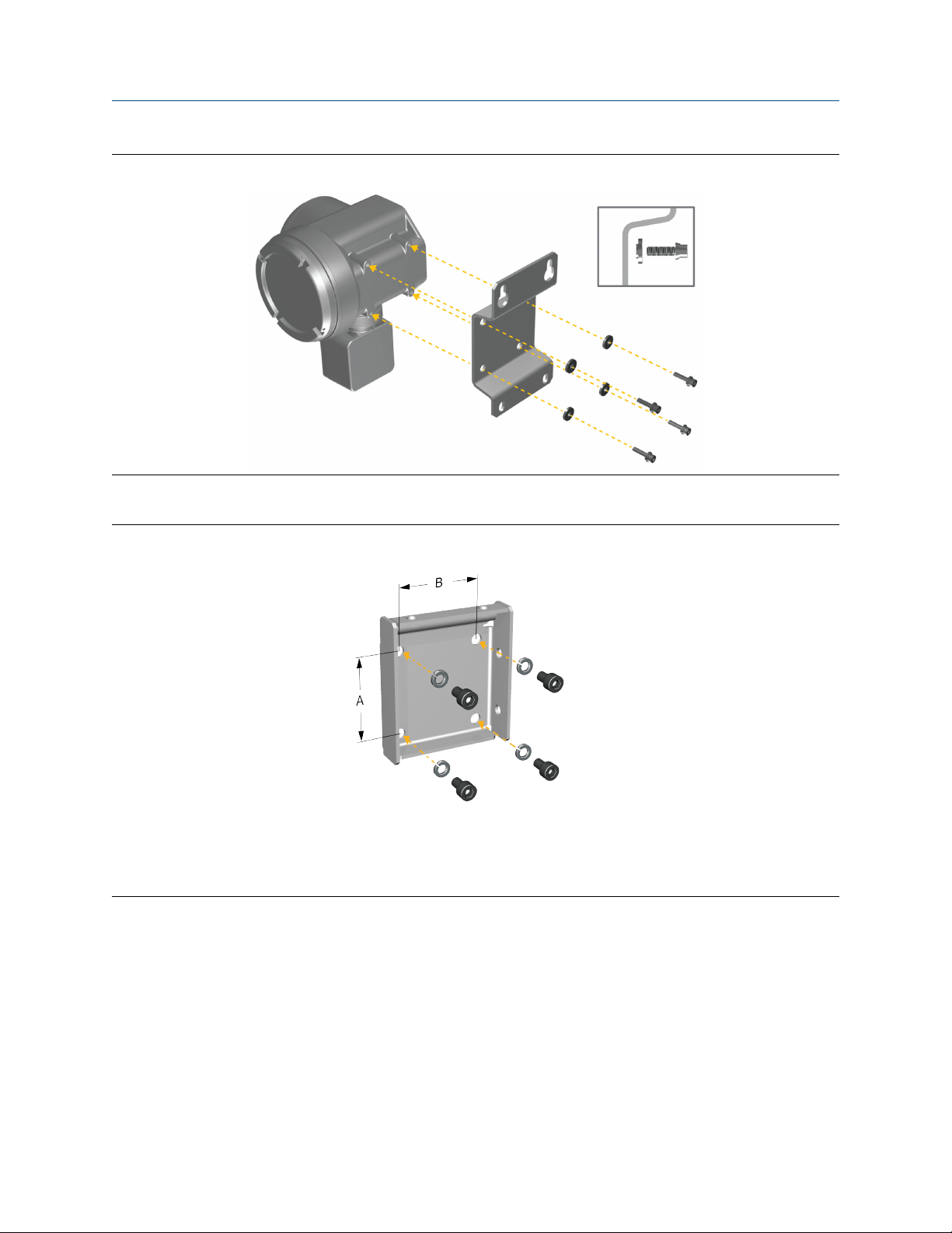
Figure 3-2: Mounting bracket to a stainless steel transmitter
2. For wall-mount installations, secure the mounting bracket to the prepared surface.
Figure 3-3: Wall-mounting bracket and dimensions for an aluminum transmitter
A. 2.8 in (71 mm)
B. 2.8 in (71 mm)
12 Micro Motion 5700 transmitters for PROFIBUS PA
Installation Manual Mounting and sensor wiring
MMI-20075112 August 2020
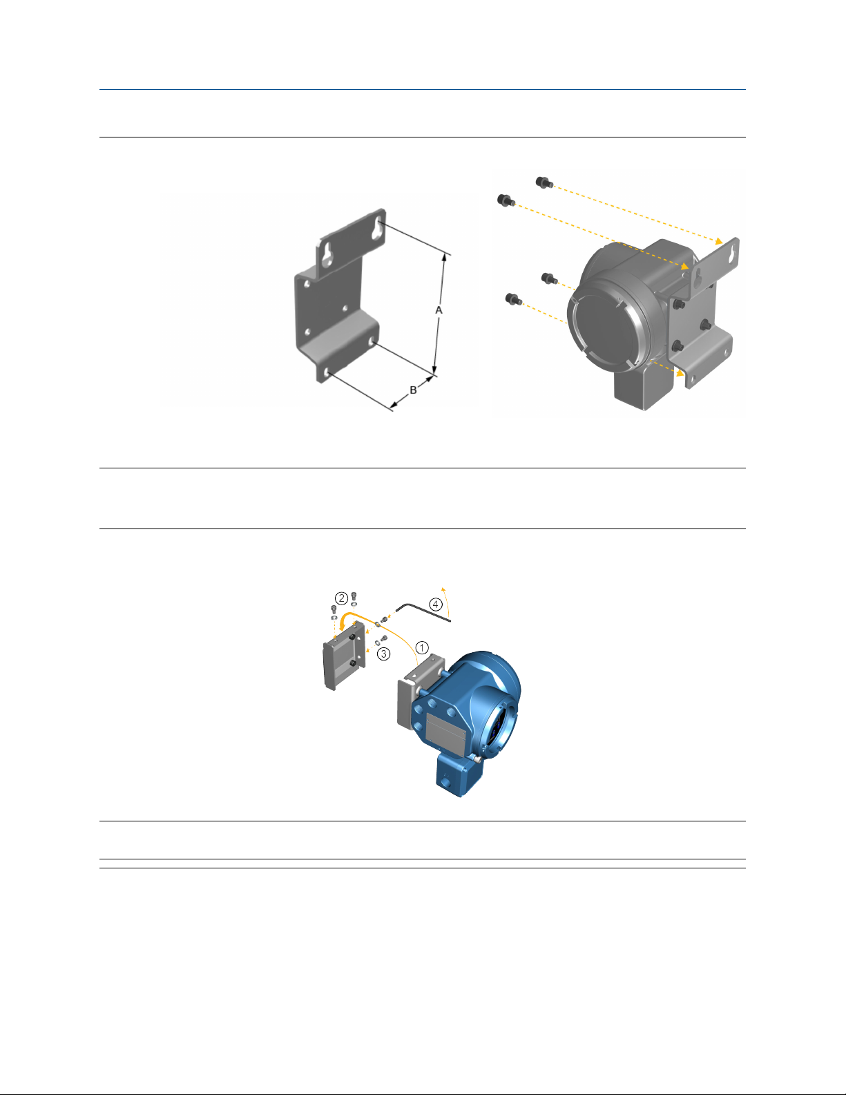
Figure 3-4: Wall-mounting bracket and dimensions for a stainless steel transmitter
A. 7.51 in (190.8 mm)
B. 3.67 in (93.2 mm)
3. For aluminum transmitters, place and attach the transmitter-mounting bracket to the mounting
bracket secured to the wall or instrument pole.
Figure 3-5: Attaching and securing an aluminum transmitter to the mounting bracket
Tip
To ensure the mounting bracket holes are aligned, insert all attachment bolts into place before tightening.
Installation Manual 13
Mounting and sensor wiring Installation Manual
August 2020 MMI-20075112
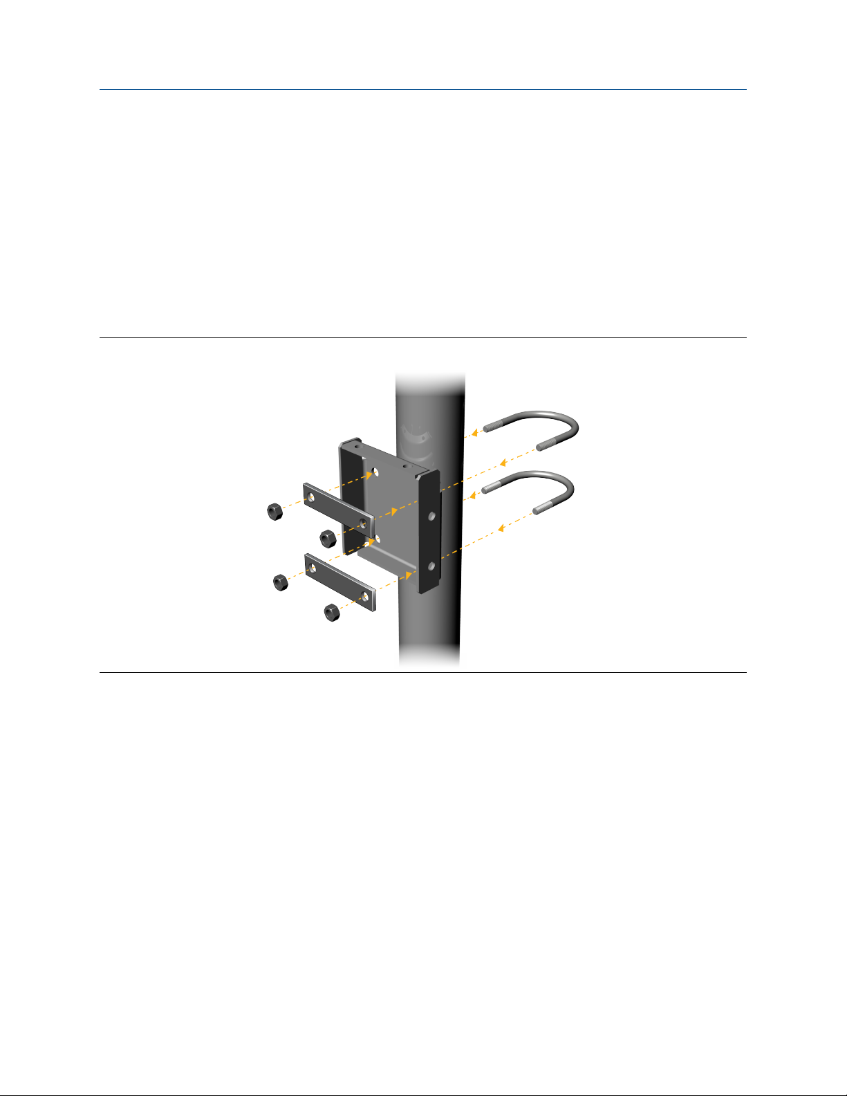
3.2.2 Mount the transmitter to a pole
Prerequisites
• Ensure that the instrument pole extends at least 12 in (305 mm) from a rigid base and is no more than 2 in
(51 mm) in diameter.
• Confirm that you have the necessary tools, and the instrument-pole mounting kit shipped with the
transmitter.
Procedure
For pole-mount installations, attach the U-bolt mounting piece to the instrument pole.
Figure 3-6: Pole-mounting bracket attachment for an aluminum transmitter
14 Micro Motion 5700 transmitters for PROFIBUS PA
 Loading...