

Installation Instructions: Canadian Standards Association Intrinsic Safety Installation Instructions 9-Wire | Micro Motion
Table of contents
 Loading...
Micro Motion Installation Instructions: Canadian Standards Association Intrinsic Safety Installation Instructions 9-Wire | Micro Motion Manuals & Guides

Installation Manual
MMI-20001968, Rev BB
CSA-D-IS Installation Instructions, 9-Wire
Preparation
October 2018

Safety and approval information
This Micro Motion product complies with all applicable European directives when properly installed in accordance with the
instructions in this manual. Refer to the EU declaration of conformity for directives that apply to this product. The EU declaration
of conformity, with all applicable European directives, and the complete ATEX Installation Drawings and Instructions are available
on the internet at www.emerson.com or through your local Micro Motion support center.
Information affixed to equipment that complies with the Pressure Equipment Directive, can be found on the internet at
www.emerson.com.
For hazardous installations in Europe, refer to standard EN 60079-14 if national standards do not apply.
Other information
Full product specifications can be found in the product data sheet. Troubleshooting information can be found in the configuration
manual. Product data sheets and manuals are available from the Micro Motion web site at www.emerson.com.
Return policy
Follow Micro Motion procedures when returning equipment. These procedures ensure legal compliance with government
transportation agencies and help provide a safe working environment for Micro Motion employees. Micro Motion will not accept
your returned equipment if you fail to follow Micro Motion procedures.
Return procedures and forms are available on our web support site at www.emerson.com, or by phoning the Micro Motion
Customer Service department.
Emerson Flow customer service
Email:
• Worldwide: flow.support@emerson.com
• Asia-Pacific: APflow.support@emerson.com
Telephone:
North and South America
United States 800-522-6277 U.K. 0870 240 1978 Australia 800 158 727
Canada +1 303-527-5200 The Netherlands +31 (0) 704 136
Mexico +41 (0) 41 7686
111
Argentina +54 11 4837 7000 Germany 0800 182 5347 Pakistan 888 550 2682
Brazil +55 15 3413 8000 Italy 8008 77334 China +86 21 2892 9000
Europe and Middle East Asia Pacific
666
France 0800 917 901 India 800 440 1468
Central & Eastern +41 (0) 41 7686
111
Russia/CIS +7 495 981 9811 South Korea +82 2 3438 4600
Egypt 0800 000 0015 Singapore +65 6 777 8211
Oman 800 70101 Thailand 001 800 441 6426
Qatar 431 0044 Malaysia 800 814 008
Kuwait 663 299 01
South Africa 800 991 390
Saudi Arabia 800 844 9564
UAE 800 0444 0684
New Zealand 099 128 804
Japan +81 3 5769 6803
2

Installation Manual Contents
MMI-20001968 October 2018
Contents
Chapter 1 Planning the installation................................................................................................ 7
1.1 About this document........................................................................................................................7
1.2 Hazardous area installations............................................................................................................. 7
Chapter 2 Model 1700/2700 9-wire installations ............................................................................9
2.1 Model 1700/2700 transmitter with integrally-mounted processor to junction box on CMF, F,
H, T, D, and DL sensors.....................................................................................................................10
2.2 Model 1700/2700 transmitter with integrally-mounted core processor to 9-wire junction box
for CMF300A sensor.........................................................................................................................11
2.3 Model 1700/2700 transmitter with integrally-mounted core processor to 9-wire junction box
on CMF400 sensor with booster amplifier........................................................................................12
2.4 Model 1700/2700 transmitter with integrally-mounted core processor to junction box on
D600 sensor.................................................................................................................................... 13
2.5 Model 1700/2700 transmitter with integrally-mounted core processor to 9-wire junction box
on DT sensor....................................................................................................................................14
2.6 Model 1700/2700 transmitter installation to remote core processor to 9-wire junction box on
CMF, F, T, D, and DL sensors.............................................................................................................15
2.7 Model 1700/2700 transmitter to 9-wire remote core processor to CMF300A sensor...................... 16
2.8 Model 1700/2700 transmitter to remote mount core processor to 9-wire junction box on
CMF400 sensor with booster amplifier.............................................................................................17
2.9 Model 1700/2700 transmitter to remote core processor to 9-wire junction box on D600 sensor....18
2.10 Model 1700/2700 transmitter to remote core processor to 9-wire junction box on DT sensor......19
Chapter 3 Transmitter output installation....................................................................................21
3.1 Transmitter output installation: Analog outputs for Model 1700/2700 transmitters.......................22
3.2 Transmitter output installation Model 1700/2700 with Intrinsically Safe installation...................... 23
3.3 Transmitter output installation: Model 2700 with configurable inputs and outputs........................24
3.4 Transmitter output installation Model 1700/2700 with Fieldbus.................................................... 25
3.5 Transmitter output installation: Profibus-PA outputs for Model 1700/2700 Transmitters...............26
Chapter 4 Model 3300 nonincendive parameters......................................................................... 27
Chapter 5 Model 3350 nonincendive parameters......................................................................... 29
Chapter 6 Model 3500 transmitter 9-wire installation instructions...............................................31
6.1 Model 3500 transmitter to 9-wire sensor junction box for CMF, F, H, and T sensors ....................... 32
6.2 Model 3500 transmitter to 9-wire sensor junction box for CMF300A sensor................................... 33
6.3 Model 3500 transmitter to sensor junction box for CMF400 sensor with booster amplifier............. 34
6.4 Model 3500 transmiter to sensor junction box for D and DL sensors............................................... 35
6.5 Model 3500 transmitter to 9-wire sensor junction box for D600 sensor.......................................... 36
6.6 Model 3500 transmitter to 9-wire sensor junction box for DT sensor.............................................. 37
Installation Instructions 3

Contents Installation Manual
October 2018 MMI-20001968
Chapter 7 Model 3700 9-wire installation instructions................................................................. 39
7.1 Model 3700 transmitter to sensor junction box for CMF, F, H, and T sensors...................................40
7.2 Model 3700 transmitter to sensor junction box for CMF300A sensor.............................................. 41
7.3 Model 3700 transmitter to 9-wire sensor junction box for CMF400 sensor with booster amplifier.. 42
7.4 Model 3700 transmitter to 9-wire sensor junction box for D and DL sensors................................... 43
7.5 Model 3700 transmitter to 9-wire sensor junction box for D600 sensor.......................................... 44
7.6 Model 3700 transmitter to 9-wire sensor junction box for DT sensors.............................................45
Chapter 8 RFT9739 field mount 9-wire installation instructions....................................................47
8.1 RFT9739 transmitter field mounted to sensor junction box for CMF, F, and H sensors.................... 48
8.2 RFT9739 transmitter field-mounted to 9-wire sensor junction box for CMF300A sensor.................49
8.3 RFT9739 transmitter field-mounted to sensor junction box for CMF400 sensor with booster
amplifier.......................................................................................................................................... 50
8.4 RFT9739 transmitter field-mounted to sensor junction box for D and DL sensors........................... 51
8.5 RFT9739 transmitter field-mounted to sensor junction box for D600 sensor ................................. 52
8.6 RFT9739 transmitter field-mounted to sensor junction box for DT sensors.....................................53
Chapter 9 RFT9739 rack mount 9-wire installation instructions....................................................55
9.1 RFT9739 rack mounted transmitter to sensor junction box for CMF, F, and H sensors.....................56
9.2 RFT9739 rack mounted transmitter to sensor junction box for CMF300A sensor............................ 57
9.3 RFT9739 rack mounted transmitter to sensor junction box for CMF400A sensor with booster
amplifier.......................................................................................................................................... 58
9.4 RFT9739 rack mounted transmitter to sensor junction box for D and DL sensors............................ 59
9.5 RFT9739 rack mounted transmitter to sensor junction box for D600 sensor...................................60
9.6 RFT9739 rack mounted transmitter to sensor junction box for DT sensors......................................61
Chapter 10 IFT9701 transmitter 9-wire installation instructions.....................................................63
10.1 IFT9701 transmitter to sensor junction box for CMF, F, and H sensors.......................................... 64
10.2 IFT9739 transmitter to sensor junction box for CMF300A sensor.................................................. 65
10.3 IFT9701 transmitter to sensor junction box for CMF400 sensor with booster amplifier................. 66
10.4 IFT9701 transmitter to sensor junction box for D and DL sensors..................................................67
Chapter 11 Model 1500/2500 9-wire installation instructions.........................................................69
11.1 Model 1500/2500 transmitter to remote mount core processor to 9-wire junction box on
CMF, D (except D600), DL, F, H, and T sensors................................................................................. 70
11.2 Model 1500/2500 transmitter to remote core processor to 9-wire junction box for CMF300A
sensor..............................................................................................................................................71
11.3 Model 1500/2500 transmitter to remote core processor to 9-wire junction box on CMF400
sensor with booster amplifier.......................................................................................................... 72
11.4 Model 1500/2500 transmitter to core processor to 9-wire junction box on D600 sensor.............. 73
11.5 Model 1500/2500 transmitter to core processor to 9-wire junction box on DT sensor.................. 74
Chapter 12 Model 3700 9-wire installation instructions................................................................. 75
12.1 Model 3700 transmitter to remote mount core processor to 9-wire junction box on CMF, D
(except D600), DL, F, H, and T sensors............................................................................................. 76
4 Micro Motion CSA-D-IS 9-Wire

Installation Manual Contents
MMI-20001968 October 2018
12.2 Model 3700 transmitter to remote core processor to 9-wire junction box for CMF300A sensor.... 77
12.3 Model 3700 transmitter to remote core processor to 9-wire junction box on CMF400 sensor
with booster amplifier..................................................................................................................... 78
12.4 Model 3700 transmitter to remote core processor to 9-wire junction box on D600...................... 79
12.5 Model 3700 transmitter to remote mount core processor to 9-wire junction box on DT sensor.... 80
Chapter 13 Model 3500 9-wire installation instructions................................................................. 81
13.1 Model 3500 transmitter to remote core processor to 9-wire junction box on CMF, D (except
D600), DL, H, and T sensors............................................................................................................. 82
13.2 Model 3500 transmitter to 9-wire junction box for CMF3000A sensor.......................................... 83
13.3 Model 3500 transmitter to remote core processor to 9-wire junction box on CMF400 sensor
with boost amplifier.........................................................................................................................84
13.4 Model 3500 transmitter to remote mount core processor to 9-wire junction box on D600
sensor..............................................................................................................................................85
13.5 Model 3500 transmitter to remote mount core processor to 9-wire junction box on DT sensor.... 86
Chapter 14 CMF400 booster amplifier installation instructions...................................................... 87
14.1 Booster amplifier with core processor remotely mounted from sensor and transmitter................88
14.2 Booster amplifier with junction box remotely mounted from sensor and transmitter................... 89
Chapter 15 D600 remote booster amplifier installation.................................................................. 91
15.1 D600 remote booster amplifier installation with core processor remotely mounted from
sensor and transmitter.....................................................................................................................92
15.2 D600 remote booster amplifier with junction box remotely mounted from sensor and
transmitter...................................................................................................................................... 93
Appendix A List of drawings............................................................................................................95
Installation Instructions 5

Contents Installation Manual
October 2018 MMI-20001968
6 Micro Motion CSA-D-IS 9-Wire

Installation Manual Planning the installation
MMI-20001968 October 2018
1 Planning the installation
1.1 About this document
This manual should be used for any Micro Motion flowmeter installation that require
Canadian Standards Association (CSA) approval.
The information in this document assumes that users understand:
• Basic transmitter and sensor installation concepts and procedures
• All corporate, local government, and national government safety standards and
requirements that guard against injuries and death
This manual provides only information associated with installation of transmitters through
CSA-D-IS instructions. For complete information on flowmeter installation, see the
documentation provided with your sensor and transmitter.
1.2 Hazardous area installations
If your cable will be installed in a hazardous area, ensure that it meets the hazardous area
requirements.
DANGER
Failure to maintain intrinsic safety in a hazardous area could result in an explosion.
To keep sensor wiring intrinsically safe:
• Keep intrinsically safe (IS) sensor wiring separate from power supply wiring and output
wiring.
• Do not install power cable in the same conduit or cable tray as flowmeter cable.
• Use this document with the appropriate approvals documentation. These manuals are
shipped with the flowmeter or available on the Emerson web site: www.emerson.com.
• For hazardous area installations in Europe, refer to standard EN 60079-14 if national
standards do not apply.
Installation Instructions 7

Planning the installation Installation Manual
October 2018 MMI-20001968
8 Micro Motion CSA-D-IS 9-Wire

Installation Manual Model 1700/2700 9-wire installations
MMI-20001968 October 2018
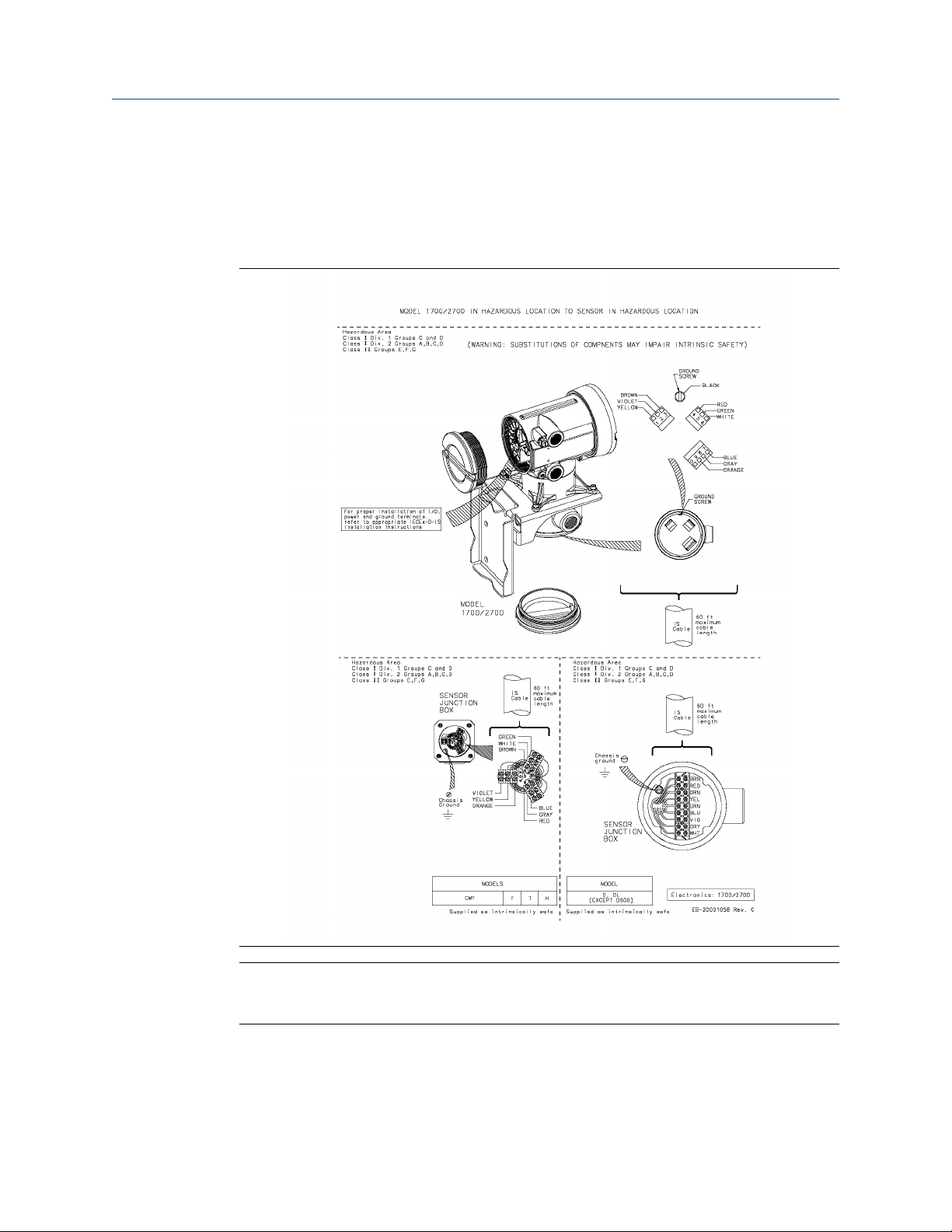
2 Model 1700/2700 9-wire installations
Table 2-1: List of Drawings for Model 1700/2700 9-wire installations
Drawing name Location
EB-20001058, Revision, C Model 1700/2700 transmitter with integrally-mounted processor to
junction box on CMF, F, H, T, D, and DL sensors
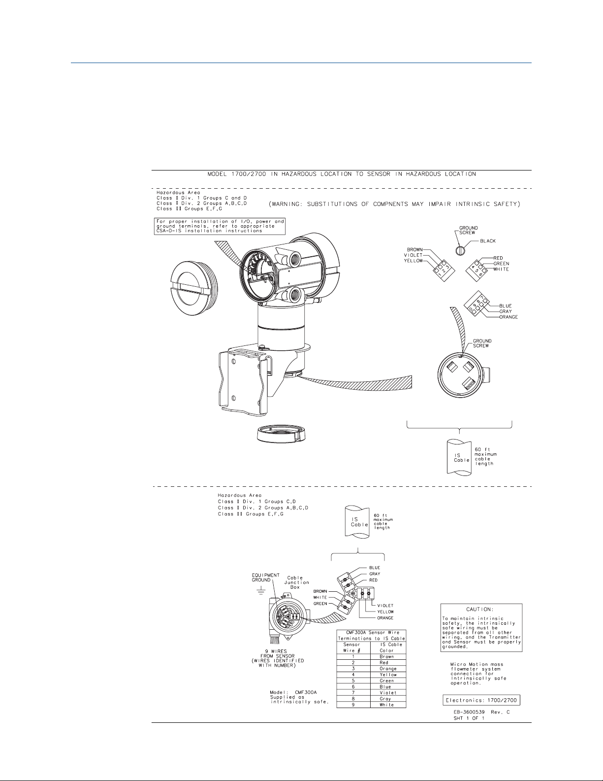
EB-3600539, Revision C Model 1700/2700 transmitter with integrally-mounted core
processor to 9-wire junction box for CMF300A sensor
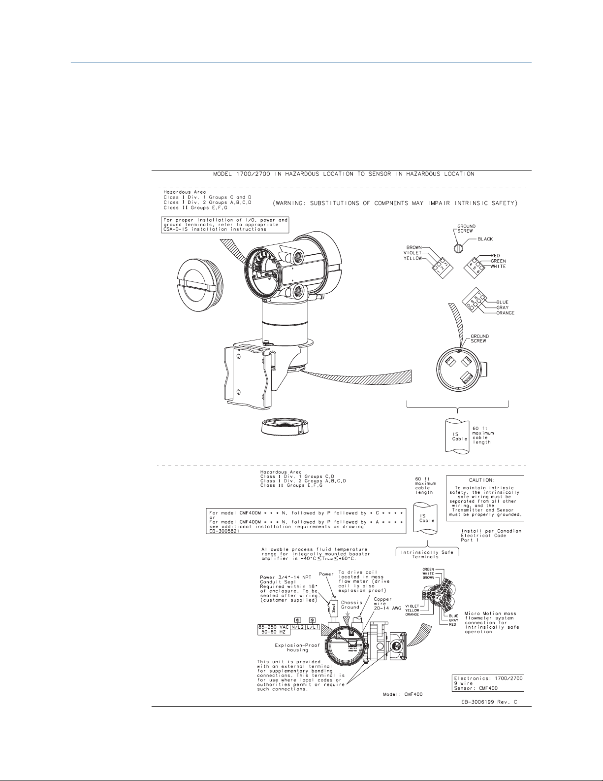
EB-3006199, Revision C Model 1700/2700 transmitter with integrally-mounted core
processor to 9-wire junction box on CMF400 sensor with booster
amplifier
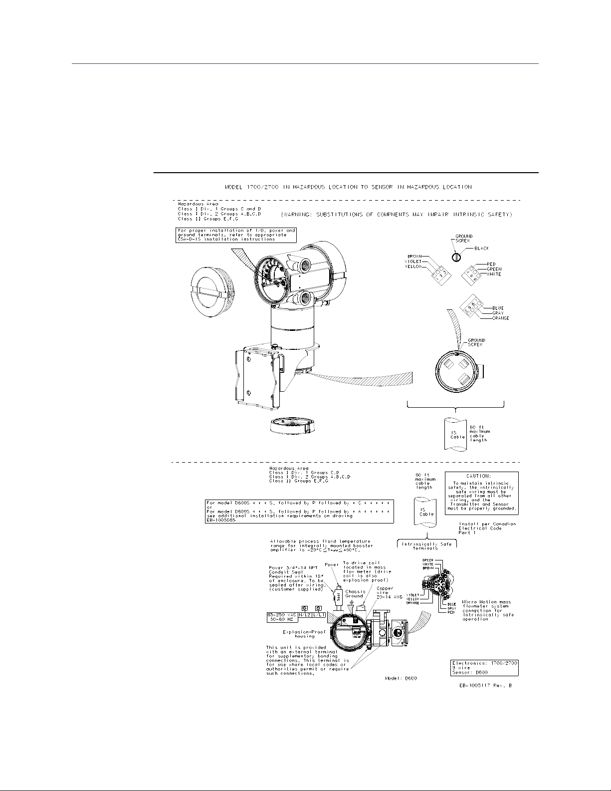
EB-10005117 Revision B Model 1700/2700 transmitter with integrally-mounted core
processor to junction box on D600 sensor
EB-3600538, Revision B Model 1700/2700 transmitter with integrally-mounted core
processor to 9-wire junction box on DT sensor
EB-20001060, Revision, BA Model 1700/2700 transmitter installation to remote core processor
to 9-wire junction box on CMF, F, T, D, and DL sensors
EB-3600675, Revision D Model 1700/2700 transmitter to 9-wire remote core processor to
CMF300A sensor
EB-3007061, Revision B Model 1700/2700 transmitter to remote mount core processor to 9-
wire junction box on CMF400 sensor with booster amplifier
EB-1005119 Revision B Model 1700/2700 transmitter to remote core processor to 9-wire
junction box on D600 sensor
EB-3600674, Revision C Model 1700/2700 transmitter to remote core processor to 9-wire
junction box on DT sensor
Installation Instructions 9
Model 1700/2700 9-wire installations Installation Manual
October 2018 MMI-20001968
2.1 Model 1700/2700 transmitter with integrallymounted processor to junction box on CMF, F,
H, T, D, and DL sensors
Note
This installation process does not apply to CMF400 sensors with a booster amplifier or to
D600 sensors.
10 Micro Motion CSA-D-IS 9-Wire
Installation Manual Model 1700/2700 9-wire installations
MMI-20001968 October 2018
2.2 Model 1700/2700 transmitter with integrallymounted core processor to 9-wire junction box
for CMF300A sensor
Installation Instructions 11
Model 1700/2700 9-wire installations Installation Manual
October 2018 MMI-20001968
2.3 Model 1700/2700 transmitter with integrallymounted core processor to 9-wire junction box
on CMF400 sensor with booster amplifier
12 Micro Motion CSA-D-IS 9-Wire
Installation Manual Model 1700/2700 9-wire installations
MMI-20001968 October 2018
2.4 Model 1700/2700 transmitter with integrallymounted core processor to junction box on
D600 sensor
Installation Instructions 13
Model 1700/2700 9-wire installations Installation Manual
October 2018 MMI-20001968
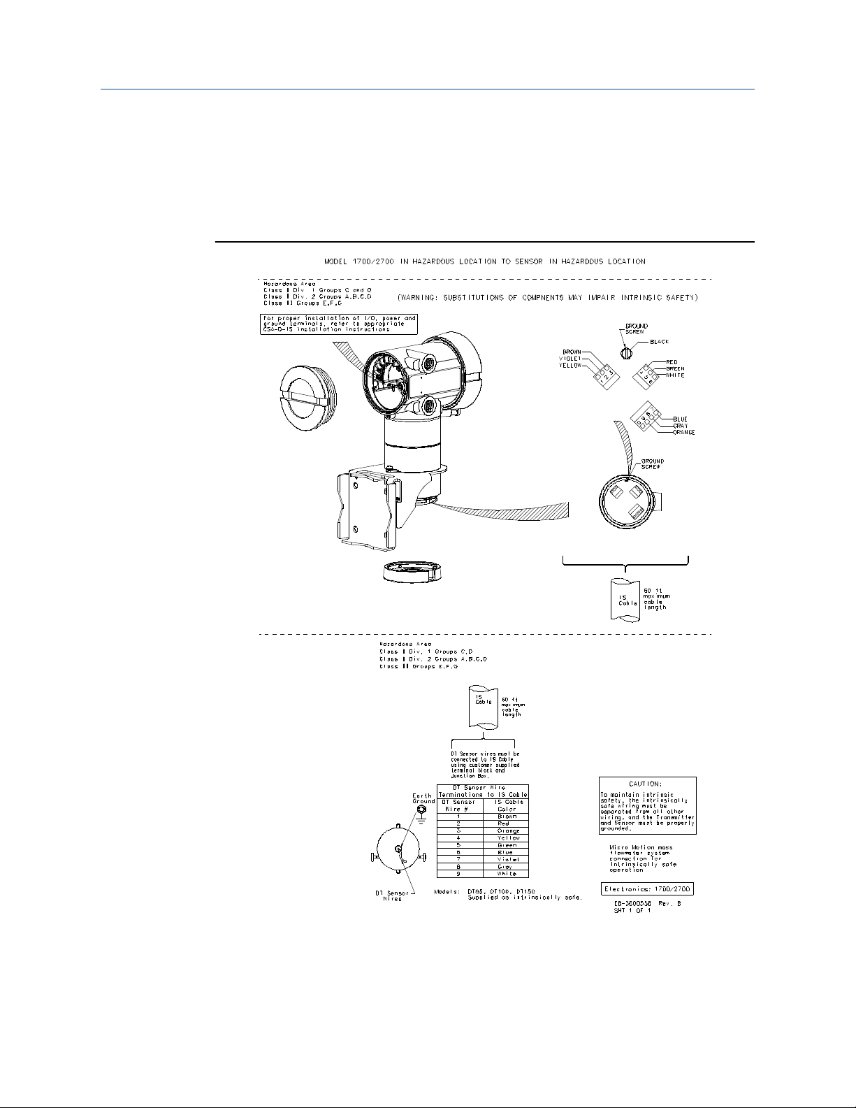
2.5 Model 1700/2700 transmitter with integrallymounted core processor to 9-wire junction box
on DT sensor
14 Micro Motion CSA-D-IS 9-Wire

Installation Manual Model 1700/2700 9-wire installations
MMI-20001968 October 2018
2.6 Model 1700/2700 transmitter installation to remote core processor to 9-wire junction box on CMF, F, T, D, and DL sensors
Note
This installation process does not apply to CMF400 sensors with a booster amplifier or to
D600 sensors.
Installation Instructions 15

Model 1700/2700 9-wire installations Installation Manual
October 2018 MMI-20001968
2.7 Model 1700/2700 transmitter to 9-wire remote core processor to CMF300A sensor
Note
This installation process does not apply to CMF400 sensors with a booster amplifier or to
D600 sensors.
16 Micro Motion CSA-D-IS 9-Wire

Installation Manual Model 1700/2700 9-wire installations
MMI-20001968 October 2018
2.8 Model 1700/2700 transmitter to remote mount core processor to 9-wire junction box on CMF400 sensor with booster amplifier
Installation Instructions 17

Model 1700/2700 9-wire installations Installation Manual
October 2018 MMI-20001968
2.9 Model 1700/2700 transmitter to remote core processor to 9-wire junction box on D600 sensor
18 Micro Motion CSA-D-IS 9-Wire

Installation Manual Model 1700/2700 9-wire installations
MMI-20001968 October 2018
2.10 Model 1700/2700 transmitter to remote core processor to 9-wire junction box on DT sensor
Installation Instructions 19

Model 1700/2700 9-wire installations Installation Manual
October 2018 MMI-20001968
20 Micro Motion CSA-D-IS 9-Wire

Installation Manual Transmitter output installation
MMI-20001968 October 2018
3 Transmitter output installation
Table 3-1: List of Drawings for Transmitter output installations
Drawing name Location
EB-3600479, Revision CA Transmitter output installation: Analog outputs for Model
1700/2700 transmitters
EB-3600629, Revision D Transmitter output installation Model 1700/2700 with Intrinsically
Safe installation
EB-3600667, Revision B Transmitter output installation: Model 2700 with configurable
inputs and outputs
EB-3600476, Revision DA Transmitter output installation Model 1700/2700 with Fieldbus
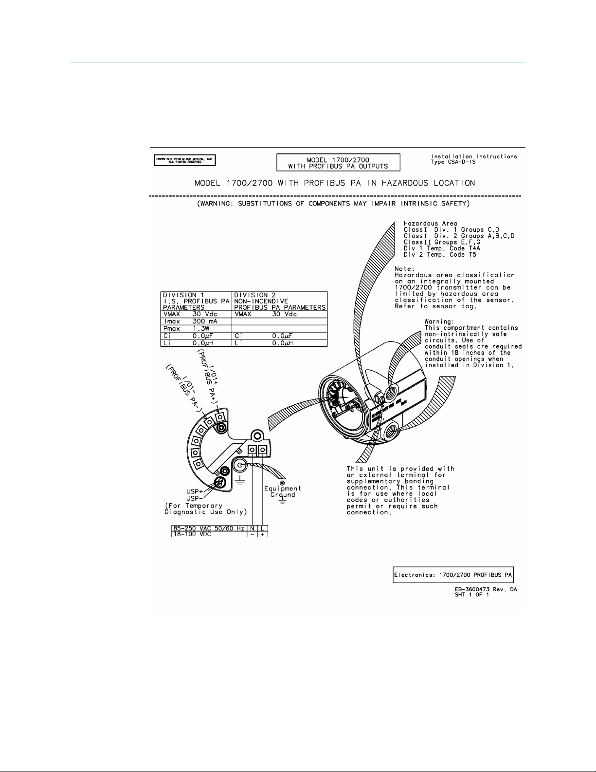
EB-3600473, Revision DA Transmitter output installation: Profibus-PA outputs for Model
1700/2700 Transmitters
Installation Instructions 21

Transmitter output installation Installation Manual
October 2018 MMI-20001968
3.1 Transmitter output installation: Analog outputs for Model 1700/2700 transmitters
22 Micro Motion CSA-D-IS 9-Wire

Installation Manual Transmitter output installation
MMI-20001968 October 2018
3.2 Transmitter output installation Model 1700/2700 with Intrinsically Safe installation
Installation Instructions 23

Transmitter output installation Installation Manual
October 2018 MMI-20001968
3.3 Transmitter output installation: Model 2700 with configurable inputs and outputs
24 Micro Motion CSA-D-IS 9-Wire

Installation Manual Transmitter output installation
MMI-20001968 October 2018
3.4 Transmitter output installation Model 1700/2700 with Fieldbus
Installation Instructions 25
Transmitter output installation Installation Manual
October 2018 MMI-20001968
3.5 Transmitter output installation: Profibus-PA outputs for Model 1700/2700 Transmitters
26 Micro Motion CSA-D-IS 9-Wire

Installation Manual Model 3300 nonincendive parameters
MMI-20001968 October 2018
4 Model 3300 nonincendive
parameters
Installation Instructions 27

Model 3300 nonincendive parameters Installation Manual
October 2018 MMI-20001968
28 Micro Motion CSA-D-IS 9-Wire
Installation Manual Model 3350 nonincendive parameters
MMI-20001968 October 2018
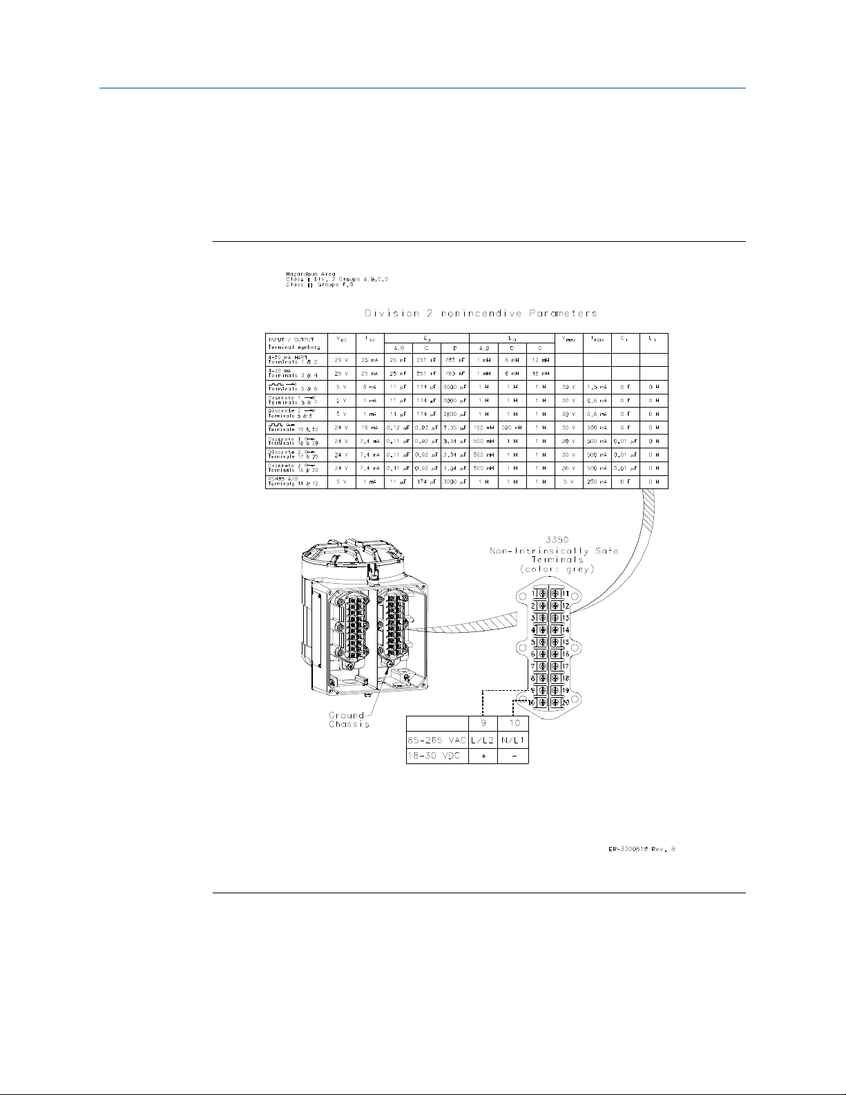
5 Model 3350 nonincendive
parameters
Installation Instructions 29

Model 3350 nonincendive parameters Installation Manual
October 2018 MMI-20001968
30 Micro Motion CSA-D-IS 9-Wire
Loading...