

Page 1

Configuration and Use Manual
P/N 20002983, Rev. A
October 2005
Micro Motion
®
Model 3711
Gas Flow Computers
Configuration and Use Manual
Page 2

©2005, Micro Motion, Inc. All rights reserved. ELITE, ProLink, and the Micro Motion logo are registered trademarks of Micro
Motion, Inc., Boulder, Colorado. MVD and MVD Direct Connect are trademarks of Micro Motion., Inc., Boulder, Colorado. Micro
Motion is a registered trade name of Micro Motion, Inc., Boulder, Colorado. The Emerson logo is a trademark of Emerson Electric
Co. All other trademarks are property of their respective owners.
Page 3

Contents
Chapter 1 Before You Begin . . . . . . . . . . . . . . . . . . . . . . . . . . . . . . . . . . . . . 1
1.1 Overview . . . . . . . . . . . . . . . . . . . . . . . . . . . . . . . . . . . . . . . . . . . . . . . . . . . . . . . . . . . 1
1.2 Safety . . . . . . . . . . . . . . . . . . . . . . . . . . . . . . . . . . . . . . . . . . . . . . . . . . . . . . . . . . . . . 1
1.3 About the Model 3711 Gas Flow Computer . . . . . . . . . . . . . . . . . . . . . . . . . . . . . . . . 1
1.3.1 Model 3711 system components . . . . . . . . . . . . . . . . . . . . . . . . . . . . . . . . 1
1.3.2 User programs . . . . . . . . . . . . . . . . . . . . . . . . . . . . . . . . . . . . . . . . . . . . . . 1
1.3.3 Implementation overview . . . . . . . . . . . . . . . . . . . . . . . . . . . . . . . . . . . . . . 2
1.4 Communication tools. . . . . . . . . . . . . . . . . . . . . . . . . . . . . . . . . . . . . . . . . . . . . . . . . . 2
1.5 Model 3711 configuration overview. . . . . . . . . . . . . . . . . . . . . . . . . . . . . . . . . . . . . . . 2
1.5.1 Quick start . . . . . . . . . . . . . . . . . . . . . . . . . . . . . . . . . . . . . . . . . . . . . . . . . 2
1.5.2 Basic configuration. . . . . . . . . . . . . . . . . . . . . . . . . . . . . . . . . . . . . . . . . . . 3
1.5.3 Advanced options . . . . . . . . . . . . . . . . . . . . . . . . . . . . . . . . . . . . . . . . . . . 3
1.6 Model 3711 administration overview . . . . . . . . . . . . . . . . . . . . . . . . . . . . . . . . . . . . . . 4
1.7 Documentation resources . . . . . . . . . . . . . . . . . . . . . . . . . . . . . . . . . . . . . . . . . . . . . . 4
1.8 Micro Motion customer service . . . . . . . . . . . . . . . . . . . . . . . . . . . . . . . . . . . . . . . . . . 4
Chapter 2 Getting Started. . . . . . . . . . . . . . . . . . . . . . . . . . . . . . . . . . . . . . . 5
2.1 Overview . . . . . . . . . . . . . . . . . . . . . . . . . . . . . . . . . . . . . . . . . . . . . . . . . . . . . . . . . . . 5
2.2 Starting the Model 3711 . . . . . . . . . . . . . . . . . . . . . . . . . . . . . . . . . . . . . . . . . . . . . . . 5
2.3 Installing ROCLINK 800 . . . . . . . . . . . . . . . . . . . . . . . . . . . . . . . . . . . . . . . . . . . . . . . 6
2.3.1 PC requirements for ROCLINK 800 . . . . . . . . . . . . . . . . . . . . . . . . . . . . . . 6
2.3.2 Installing ROCLINK 800. . . . . . . . . . . . . . . . . . . . . . . . . . . . . . . . . . . . . . . 6
2.4 Using ROCLINK 800 . . . . . . . . . . . . . . . . . . . . . . . . . . . . . . . . . . . . . . . . . . . . . . . . . . 7
2.4.1 Starting ROCLINK 800 . . . . . . . . . . . . . . . . . . . . . . . . . . . . . . . . . . . . . . . 7
2.4.2 ROCLINK 800 user interface . . . . . . . . . . . . . . . . . . . . . . . . . . . . . . . . . . . 7
2.4.3 TLP system . . . . . . . . . . . . . . . . . . . . . . . . . . . . . . . . . . . . . . . . . . . . . . . 10
2.5 Configuration files . . . . . . . . . . . . . . . . . . . . . . . . . . . . . . . . . . . . . . . . . . . . . . . . . . . 11
2.5.1 Managing device configuration files . . . . . . . . . . . . . . . . . . . . . . . . . . . . . 11
2.5.2 Creating a new device configuration file . . . . . . . . . . . . . . . . . . . . . . . . . 11
2.5.3 Device configuration backup and duplication. . . . . . . . . . . . . . . . . . . . . . 13
2.6 Setting up devices and groups . . . . . . . . . . . . . . . . . . . . . . . . . . . . . . . . . . . . . . . . . 13
2.7 First connection to the Model 3711 . . . . . . . . . . . . . . . . . . . . . . . . . . . . . . . . . . . . . . 13
2.7.1 Disconnecting and closing . . . . . . . . . . . . . . . . . . . . . . . . . . . . . . . . . . . . 14
Chapter 3 System Configuration . . . . . . . . . . . . . . . . . . . . . . . . . . . . . . . . . 15
3.1 Overview . . . . . . . . . . . . . . . . . . . . . . . . . . . . . . . . . . . . . . . . . . . . . . . . . . . . . . . . . . 15
3.2 Setting the Model 3711 clock . . . . . . . . . . . . . . . . . . . . . . . . . . . . . . . . . . . . . . . . . . 15
3.3 Configuring security . . . . . . . . . . . . . . . . . . . . . . . . . . . . . . . . . . . . . . . . . . . . . . . . . 16
3.3.1 ROCLINK 800 security. . . . . . . . . . . . . . . . . . . . . . . . . . . . . . . . . . . . . . . 16
3.3.2 Device security. . . . . . . . . . . . . . . . . . . . . . . . . . . . . . . . . . . . . . . . . . . . . 17
3.3.3 Access level . . . . . . . . . . . . . . . . . . . . . . . . . . . . . . . . . . . . . . . . . . . . . . . 19
3.4 Configuring Model 3711 device information . . . . . . . . . . . . . . . . . . . . . . . . . . . . . . . 21
3.5 Configuring display options . . . . . . . . . . . . . . . . . . . . . . . . . . . . . . . . . . . . . . . . . . . . 23
Configuration and Use Manual i
Page 4

Contents
Chapter 4 Setting Up Communications. . . . . . . . . . . . . . . . . . . . . . . . . . . . . 25
4.1 Overview . . . . . . . . . . . . . . . . . . . . . . . . . . . . . . . . . . . . . . . . . . . . . . . . . . . . . . . . . . 25
4.2 Communications overview . . . . . . . . . . . . . . . . . . . . . . . . . . . . . . . . . . . . . . . . . . . . 25
4.3 Connecting to the Model 3711 through the LOI . . . . . . . . . . . . . . . . . . . . . . . . . . . . 26
4.4 Connecting to the Model 3711 through COMM 2 . . . . . . . . . . . . . . . . . . . . . . . . . . . 26
4.4.1 Using ROCLINK 800 . . . . . . . . . . . . . . . . . . . . . . . . . . . . . . . . . . . . . . . . 26
4.4.2 Using a host program . . . . . . . . . . . . . . . . . . . . . . . . . . . . . . . . . . . . . . . 27
4.5 Configuring communications parameters . . . . . . . . . . . . . . . . . . . . . . . . . . . . . . . . . 27
4.5.1 Configuring COMM 2 on the Model 3711 . . . . . . . . . . . . . . . . . . . . . . . . 27
4.5.2 Configuring ROCLINK 800 communications parameters . . . . . . . . . . . . 30
4.6 Configuring communications for RBX alarming . . . . . . . . . . . . . . . . . . . . . . . . . . . . 32
4.7 Configuring passthrough mode. . . . . . . . . . . . . . . . . . . . . . . . . . . . . . . . . . . . . . . . . 34
Chapter 5 Configuring the Core Interface . . . . . . . . . . . . . . . . . . . . . . . . . . . 37
5.1 About this chapter . . . . . . . . . . . . . . . . . . . . . . . . . . . . . . . . . . . . . . . . . . . . . . . . . . . 37
5.2 Configuration overview . . . . . . . . . . . . . . . . . . . . . . . . . . . . . . . . . . . . . . . . . . . . . . . 37
5.3 Using ROCLINK 800 with the Micro Motion core interface . . . . . . . . . . . . . . . . . . . . 38
5.4 Core interface configuration panels . . . . . . . . . . . . . . . . . . . . . . . . . . . . . . . . . . . . . 38
5.4.1 Mass Flow panel . . . . . . . . . . . . . . . . . . . . . . . . . . . . . . . . . . . . . . . . . . . 38
5.4.2 Density panel . . . . . . . . . . . . . . . . . . . . . . . . . . . . . . . . . . . . . . . . . . . . . . 40
5.4.3 Temperature panel. . . . . . . . . . . . . . . . . . . . . . . . . . . . . . . . . . . . . . . . . . 41
5.5 Special topics in configuring the core interface. . . . . . . . . . . . . . . . . . . . . . . . . . . . . 43
5.5.1 Characterization . . . . . . . . . . . . . . . . . . . . . . . . . . . . . . . . . . . . . . . . . . . 43
5.5.2 Damping . . . . . . . . . . . . . . . . . . . . . . . . . . . . . . . . . . . . . . . . . . . . . . . . . 44
5.5.3 Meter factors . . . . . . . . . . . . . . . . . . . . . . . . . . . . . . . . . . . . . . . . . . . . . . 44
5.5.4 Slug flow . . . . . . . . . . . . . . . . . . . . . . . . . . . . . . . . . . . . . . . . . . . . . . . . . 45
5.6 Zeroing the meter . . . . . . . . . . . . . . . . . . . . . . . . . . . . . . . . . . . . . . . . . . . . . . . . . . . 46
Chapter 6 Configuring Volumetric Flow Measurement . . . . . . . . . . . . . . . . . . 49
6.1 About this chapter . . . . . . . . . . . . . . . . . . . . . . . . . . . . . . . . . . . . . . . . . . . . . . . . . . . 49
6.2 Terminology. . . . . . . . . . . . . . . . . . . . . . . . . . . . . . . . . . . . . . . . . . . . . . . . . . . . . . . . 49
6.3 Configuration overview . . . . . . . . . . . . . . . . . . . . . . . . . . . . . . . . . . . . . . . . . . . . . . . 49
6.3.1 Input Defs panel . . . . . . . . . . . . . . . . . . . . . . . . . . . . . . . . . . . . . . . . . . . 49
6.3.2 Mass Compensation panel . . . . . . . . . . . . . . . . . . . . . . . . . . . . . . . . . . . 51
6.4 Gas Quality panel . . . . . . . . . . . . . . . . . . . . . . . . . . . . . . . . . . . . . . . . . . . . . . . . . . . 53
6.4.1 Advanced panel . . . . . . . . . . . . . . . . . . . . . . . . . . . . . . . . . . . . . . . . . . . . 54
6.4.2 Sampler panel . . . . . . . . . . . . . . . . . . . . . . . . . . . . . . . . . . . . . . . . . . . . . 56
6.5 AO Assignment panel . . . . . . . . . . . . . . . . . . . . . . . . . . . . . . . . . . . . . . . . . . . . . . . . 57
6.5.1 Alarms panel . . . . . . . . . . . . . . . . . . . . . . . . . . . . . . . . . . . . . . . . . . . . . . 58
Chapter 7 Configuring I/O . . . . . . . . . . . . . . . . . . . . . . . . . . . . . . . . . . . . . 61
7.1 About this chapter . . . . . . . . . . . . . . . . . . . . . . . . . . . . . . . . . . . . . . . . . . . . . . . . . . . 61
7.2 Overview . . . . . . . . . . . . . . . . . . . . . . . . . . . . . . . . . . . . . . . . . . . . . . . . . . . . . . . . . . 61
7.3 Configuring I/O type . . . . . . . . . . . . . . . . . . . . . . . . . . . . . . . . . . . . . . . . . . . . . . . . . 62
7.4 Configuring analog inputs . . . . . . . . . . . . . . . . . . . . . . . . . . . . . . . . . . . . . . . . . . . . . 62
7.4.1 Filtering . . . . . . . . . . . . . . . . . . . . . . . . . . . . . . . . . . . . . . . . . . . . . . . . . . 63
7.4.2 Analog Input – General panel . . . . . . . . . . . . . . . . . . . . . . . . . . . . . . . . . 64
7.4.3 Analog Input – Advanced panel . . . . . . . . . . . . . . . . . . . . . . . . . . . . . . . . 64
7.4.4 Analog Input – Alarms panel . . . . . . . . . . . . . . . . . . . . . . . . . . . . . . . . . . 66
ii Micro Motion® Model 3711 Gas Flow Computers
Page 5

Contents
7.5 Configuring an analog output . . . . . . . . . . . . . . . . . . . . . . . . . . . . . . . . . . . . . . . . . . 67
7.5.1 Analog Output – General panel . . . . . . . . . . . . . . . . . . . . . . . . . . . . . . . . 68
7.5.2 Analog Output – Advanced panel . . . . . . . . . . . . . . . . . . . . . . . . . . . . . . 68
7.6 Configuring discrete inputs . . . . . . . . . . . . . . . . . . . . . . . . . . . . . . . . . . . . . . . . . . . . 70
7.6.1 Discrete Input – General panel . . . . . . . . . . . . . . . . . . . . . . . . . . . . . . . . 70
7.6.2 Discrete Input – Advanced panel . . . . . . . . . . . . . . . . . . . . . . . . . . . . . . . 71
7.6.3 Discrete Input – Alarms panel . . . . . . . . . . . . . . . . . . . . . . . . . . . . . . . . . 72
7.7 Configuring the discrete outputs . . . . . . . . . . . . . . . . . . . . . . . . . . . . . . . . . . . . . . . . 74
7.7.1 Discrete Output – General panel . . . . . . . . . . . . . . . . . . . . . . . . . . . . . . . 74
7.7.2 Discrete Output – Advanced panel . . . . . . . . . . . . . . . . . . . . . . . . . . . . . 76
7.7.3 Discrete Output – TDO Parameters panel . . . . . . . . . . . . . . . . . . . . . . . . 76
7.8 DOUT Type options and examples . . . . . . . . . . . . . . . . . . . . . . . . . . . . . . . . . . . . . . 78
7.8.1 Accuracy of Time Duration and TDO Toggle . . . . . . . . . . . . . . . . . . . . . . 78
7.8.2 Durations . . . . . . . . . . . . . . . . . . . . . . . . . . . . . . . . . . . . . . . . . . . . . . . . . 78
7.8.3 Examples . . . . . . . . . . . . . . . . . . . . . . . . . . . . . . . . . . . . . . . . . . . . . . . . . 78
7.9 Configuring pulse inputs . . . . . . . . . . . . . . . . . . . . . . . . . . . . . . . . . . . . . . . . . . . . . . 79
7.9.1 Pulse Input – General panel . . . . . . . . . . . . . . . . . . . . . . . . . . . . . . . . . . 80
7.9.2 Pulse Input – Advanced panel . . . . . . . . . . . . . . . . . . . . . . . . . . . . . . . . . 81
7.9.3 Pulse Input – Alarms panel . . . . . . . . . . . . . . . . . . . . . . . . . . . . . . . . . . . 82
Chapter 8 Managing History, Events, and Alarms . . . . . . . . . . . . . . . . . . . . . 85
8.1 About this chapter . . . . . . . . . . . . . . . . . . . . . . . . . . . . . . . . . . . . . . . . . . . . . . . . . . . 85
8.2 Overview . . . . . . . . . . . . . . . . . . . . . . . . . . . . . . . . . . . . . . . . . . . . . . . . . . . . . . . . . . 85
8.2.1 History . . . . . . . . . . . . . . . . . . . . . . . . . . . . . . . . . . . . . . . . . . . . . . . . . . . 85
8.2.2 Events and alarms . . . . . . . . . . . . . . . . . . . . . . . . . . . . . . . . . . . . . . . . . . 85
8.3 Configuring history points . . . . . . . . . . . . . . . . . . . . . . . . . . . . . . . . . . . . . . . . . . . . . 86
8.3.1 Archive types . . . . . . . . . . . . . . . . . . . . . . . . . . . . . . . . . . . . . . . . . . . . . . 88
8.3.2 Standard history predefined points . . . . . . . . . . . . . . . . . . . . . . . . . . . . . 89
8.4 Using the historical databases . . . . . . . . . . . . . . . . . . . . . . . . . . . . . . . . . . . . . . . . . 90
8.4.1 Viewing history data. . . . . . . . . . . . . . . . . . . . . . . . . . . . . . . . . . . . . . . . . 90
8.4.2 Viewing alarm logs and event logs. . . . . . . . . . . . . . . . . . . . . . . . . . . . . . 91
8.4.3 Using the log display window . . . . . . . . . . . . . . . . . . . . . . . . . . . . . . . . . . 91
Chapter 9 Monitoring and Displays . . . . . . . . . . . . . . . . . . . . . . . . . . . . . . . 93
9.1 About this chapter . . . . . . . . . . . . . . . . . . . . . . . . . . . . . . . . . . . . . . . . . . . . . . . . . . . 93
9.2 Model 3711 display variables . . . . . . . . . . . . . . . . . . . . . . . . . . . . . . . . . . . . . . . . . . 93
9.2.1 Display rules . . . . . . . . . . . . . . . . . . . . . . . . . . . . . . . . . . . . . . . . . . . . . . 93
9.2.2 Configuring display variables . . . . . . . . . . . . . . . . . . . . . . . . . . . . . . . . . . 94
9.3 ROCLINK 800 I/O monitor . . . . . . . . . . . . . . . . . . . . . . . . . . . . . . . . . . . . . . . . . . . . 94
9.4 ROCLINK 800 custom displays. . . . . . . . . . . . . . . . . . . . . . . . . . . . . . . . . . . . . . . . . 96
9.4.1 Creating a custom display . . . . . . . . . . . . . . . . . . . . . . . . . . . . . . . . . . . . 96
9.4.2 Saving and loading custom displays . . . . . . . . . . . . . . . . . . . . . . . . . . . . 98
9.4.3 Editing a custom display . . . . . . . . . . . . . . . . . . . . . . . . . . . . . . . . . . . . . 99
9.4.4 Using custom displays . . . . . . . . . . . . . . . . . . . . . . . . . . . . . . . . . . . . . . . 99
Chapter 10 PID Control Loops . . . . . . . . . . . . . . . . . . . . . . . . . . . . . . . . . . 101
10.1 About this chapter . . . . . . . . . . . . . . . . . . . . . . . . . . . . . . . . . . . . . . . . . . . . . . . . . . 101
10.2 PID control loops overview . . . . . . . . . . . . . . . . . . . . . . . . . . . . . . . . . . . . . . . . . . . 101
10.2.1 PID control loop example . . . . . . . . . . . . . . . . . . . . . . . . . . . . . . . . . . . . 102
10.3 Configuring a PID control loop . . . . . . . . . . . . . . . . . . . . . . . . . . . . . . . . . . . . . . . . 102
10.4 Tuning the PID control loop . . . . . . . . . . . . . . . . . . . . . . . . . . . . . . . . . . . . . . . . . . . 105
10.5 Monitoring the PID control loop. . . . . . . . . . . . . . . . . . . . . . . . . . . . . . . . . . . . . . . . 106
Configuration and Use Manual iii
Page 6

Contents
Chapter 11 Function Sequence Tables. . . . . . . . . . . . . . . . . . . . . . . . . . . . . 107
11.1 About this chapter. . . . . . . . . . . . . . . . . . . . . . . . . . . . . . . . . . . . . . . . . . . . . . . . . . 107
11.2 FST overview . . . . . . . . . . . . . . . . . . . . . . . . . . . . . . . . . . . . . . . . . . . . . . . . . . . . . 107
11.3 FSTs and Model 3711 points . . . . . . . . . . . . . . . . . . . . . . . . . . . . . . . . . . . . . . . . . 108
11.4 FST Editor. . . . . . . . . . . . . . . . . . . . . . . . . . . . . . . . . . . . . . . . . . . . . . . . . . . . . . . . 108
11.5 Developing an FST . . . . . . . . . . . . . . . . . . . . . . . . . . . . . . . . . . . . . . . . . . . . . . . . . 110
11.6 Monitoring and tracing . . . . . . . . . . . . . . . . . . . . . . . . . . . . . . . . . . . . . . . . . . . . . . 115
11.6.1 Monitor mode. . . . . . . . . . . . . . . . . . . . . . . . . . . . . . . . . . . . . . . . . . . . . 115
11.6.2 Trace mode and debugging . . . . . . . . . . . . . . . . . . . . . . . . . . . . . . . . . . 117
11.7 Using FSTs . . . . . . . . . . . . . . . . . . . . . . . . . . . . . . . . . . . . . . . . . . . . . . . . . . . . . . . 117
11.7.1 Saving, reading and downloading FSTs . . . . . . . . . . . . . . . . . . . . . . . . 117
11.7.2 Starting and stopping FSTs. . . . . . . . . . . . . . . . . . . . . . . . . . . . . . . . . . 117
11.7.3 FST storage and restart. . . . . . . . . . . . . . . . . . . . . . . . . . . . . . . . . . . . . 118
11.7.4 Deleting an FST. . . . . . . . . . . . . . . . . . . . . . . . . . . . . . . . . . . . . . . . . . . 118
11.7.5 Printing and exporting an FST. . . . . . . . . . . . . . . . . . . . . . . . . . . . . . . . 118
11.7.6 Editing an FST . . . . . . . . . . . . . . . . . . . . . . . . . . . . . . . . . . . . . . . . . . . . 118
11.7.7 Troubleshooting an FST. . . . . . . . . . . . . . . . . . . . . . . . . . . . . . . . . . . . . 119
11.8 FST command library . . . . . . . . . . . . . . . . . . . . . . . . . . . . . . . . . . . . . . . . . . . . . . . 119
11.8.1 Mathematical commands. . . . . . . . . . . . . . . . . . . . . . . . . . . . . . . . . . . . 120
11.8.2 Logical commands. . . . . . . . . . . . . . . . . . . . . . . . . . . . . . . . . . . . . . . . . 121
11.8.3 Comparison commands. . . . . . . . . . . . . . . . . . . . . . . . . . . . . . . . . . . . . 123
11.8.4 Time-related commands . . . . . . . . . . . . . . . . . . . . . . . . . . . . . . . . . . . . 124
11.8.5 Control-related commands . . . . . . . . . . . . . . . . . . . . . . . . . . . . . . . . . . 125
11.8.6 Database commands. . . . . . . . . . . . . . . . . . . . . . . . . . . . . . . . . . . . . . . 126
11.8.7 Miscellaneous commands . . . . . . . . . . . . . . . . . . . . . . . . . . . . . . . . . . . 127
11.9 FST examples . . . . . . . . . . . . . . . . . . . . . . . . . . . . . . . . . . . . . . . . . . . . . . . . . . . . . 128
11.9.1 Example 1 – Writing data to a history point . . . . . . . . . . . . . . . . . . . . . . 128
11.9.2 Example 2 – Stopping an FST after task completion . . . . . . . . . . . . . . 129
11.9.3 Example 3 – Cycling an FST on a periodic basis . . . . . . . . . . . . . . . . . 130
11.9.4 Example 4 – Calculate an FST’s approximate execution rate . . . . . . . . 131
Chapter 12 Modbus Interface . . . . . . . . . . . . . . . . . . . . . . . . . . . . . . . . . . . 133
12.1 About this chapter. . . . . . . . . . . . . . . . . . . . . . . . . . . . . . . . . . . . . . . . . . . . . . . . . . 133
12.2 Overview . . . . . . . . . . . . . . . . . . . . . . . . . . . . . . . . . . . . . . . . . . . . . . . . . . . . . . . . . 133
12.3 Modbus overview . . . . . . . . . . . . . . . . . . . . . . . . . . . . . . . . . . . . . . . . . . . . . . . . . . 133
12.4 Modbus and Model 3711 points . . . . . . . . . . . . . . . . . . . . . . . . . . . . . . . . . . . . . . . 134
12.5 Configuring the Modbus interface on the Model 3711 . . . . . . . . . . . . . . . . . . . . . . 135
12.5.1 Modbus scaling . . . . . . . . . . . . . . . . . . . . . . . . . . . . . . . . . . . . . . . . . . . 140
12.5.2 Datatype conversions . . . . . . . . . . . . . . . . . . . . . . . . . . . . . . . . . . . . . . 141
12.5.3 Modbus register ranges . . . . . . . . . . . . . . . . . . . . . . . . . . . . . . . . . . . . . 144
12.5.4 Modbus date and time formats . . . . . . . . . . . . . . . . . . . . . . . . . . . . . . . 145
12.6 Accessing Model 3711 data via the Modbus interface . . . . . . . . . . . . . . . . . . . . . . 145
12.6.1 Register addresses . . . . . . . . . . . . . . . . . . . . . . . . . . . . . . . . . . . . . . . . 145
12.6.2 Accessing history data. . . . . . . . . . . . . . . . . . . . . . . . . . . . . . . . . . . . . . 145
12.6.3 Accessing event and alarm data . . . . . . . . . . . . . . . . . . . . . . . . . . . . . . 146
Chapter 13 Model 3711 Operator Interface. . . . . . . . . . . . . . . . . . . . . . . . . . 149
13.1 About this chapter. . . . . . . . . . . . . . . . . . . . . . . . . . . . . . . . . . . . . . . . . . . . . . . . . . 149
13.2 Viewing process data and system information . . . . . . . . . . . . . . . . . . . . . . . . . . . . 149
13.2.1 Using the Rates & Totals windows. . . . . . . . . . . . . . . . . . . . . . . . . . . . . 149
13.2.2 Using the volumetric flow measurement configuration panels. . . . . . . . 151
13.2.3 Using the core interface configuration panels . . . . . . . . . . . . . . . . . . . . 151
iv Micro Motion® Model 3711 Gas Flow Computers
Page 7

Contents
13.3 Initial calculations and recalculations . . . . . . . . . . . . . . . . . . . . . . . . . . . . . . . . . . . 153
13.4 Viewing sensor alarms and communication statistics . . . . . . . . . . . . . . . . . . . . . . . 153
13.5 Reading and writing to the core processor Modbus interface . . . . . . . . . . . . . . . . . 154
Chapter 14 Administration . . . . . . . . . . . . . . . . . . . . . . . . . . . . . . . . . . . . . 157
14.1 About this chapter . . . . . . . . . . . . . . . . . . . . . . . . . . . . . . . . . . . . . . . . . . . . . . . . . . 157
14.2 Initializing the Model 3711 and managing memory. . . . . . . . . . . . . . . . . . . . . . . . . 157
14.2.1 Using the jumpers . . . . . . . . . . . . . . . . . . . . . . . . . . . . . . . . . . . . . . . . . 157
14.2.2 Using ROCLINK 800 . . . . . . . . . . . . . . . . . . . . . . . . . . . . . . . . . . . . . . . 158
14.3 Model 3711 memory structure . . . . . . . . . . . . . . . . . . . . . . . . . . . . . . . . . . . . . . . . 160
14.4 Meter default values . . . . . . . . . . . . . . . . . . . . . . . . . . . . . . . . . . . . . . . . . . . . . . . . 161
14.5 Event log . . . . . . . . . . . . . . . . . . . . . . . . . . . . . . . . . . . . . . . . . . . . . . . . . . . . . . . . . 162
14.6 Alarm log. . . . . . . . . . . . . . . . . . . . . . . . . . . . . . . . . . . . . . . . . . . . . . . . . . . . . . . . . 163
14.7 Advanced communications and system controls . . . . . . . . . . . . . . . . . . . . . . . . . . 163
14.8 Using the optional dial-up modem. . . . . . . . . . . . . . . . . . . . . . . . . . . . . . . . . . . . . . 164
14.9 Managing user programs . . . . . . . . . . . . . . . . . . . . . . . . . . . . . . . . . . . . . . . . . . . . 164
14.10 Managing device configuration files . . . . . . . . . . . . . . . . . . . . . . . . . . . . . . . . . . . . 165
14.10.1 Opening a device configuration file . . . . . . . . . . . . . . . . . . . . . . . . . . . . 165
14.10.2 Closing a device configuration file . . . . . . . . . . . . . . . . . . . . . . . . . . . . . 166
14.10.3 Downloading a device configuration file to the Model 3711 . . . . . . . . . . 166
14.11 Printing and exporting a device configuration file . . . . . . . . . . . . . . . . . . . . . . . . . . 167
14.12 Updating firmware and user programs . . . . . . . . . . . . . . . . . . . . . . . . . . . . . . . . . . 167
14.12.1 Updating the Model 3711 device firmware. . . . . . . . . . . . . . . . . . . . . . . 167
14.12.2 Updating the user programs . . . . . . . . . . . . . . . . . . . . . . . . . . . . . . . . . 169
14.13 Upgrading hardware . . . . . . . . . . . . . . . . . . . . . . . . . . . . . . . . . . . . . . . . . . . . . . . . 170
Chapter 15 Maintenance and Troubleshooting . . . . . . . . . . . . . . . . . . . . . . . 171
15.1 About this chapter . . . . . . . . . . . . . . . . . . . . . . . . . . . . . . . . . . . . . . . . . . . . . . . . . . 171
15.2 Troubleshooting the connection between ROCLINK 800 and the Model 3711 . . . . 171
15.3 Debugging ROCLINK 800 communications . . . . . . . . . . . . . . . . . . . . . . . . . . . . . . 171
15.4 Dial-up modem and FCC compliance . . . . . . . . . . . . . . . . . . . . . . . . . . . . . . . . . . . 172
15.5 Diagnostic monitoring . . . . . . . . . . . . . . . . . . . . . . . . . . . . . . . . . . . . . . . . . . . . . . . 173
15.6 Low power shutdown mode. . . . . . . . . . . . . . . . . . . . . . . . . . . . . . . . . . . . . . . . . . . 173
15.7 MPU loading . . . . . . . . . . . . . . . . . . . . . . . . . . . . . . . . . . . . . . . . . . . . . . . . . . . . . . 173
15.8 Backup battery . . . . . . . . . . . . . . . . . . . . . . . . . . . . . . . . . . . . . . . . . . . . . . . . . . . . 174
15.9 Automatic self-tests . . . . . . . . . . . . . . . . . . . . . . . . . . . . . . . . . . . . . . . . . . . . . . . . . 174
15.10 Status alarms . . . . . . . . . . . . . . . . . . . . . . . . . . . . . . . . . . . . . . . . . . . . . . . . . . . . . 174
15.11 Checking process variables and test points . . . . . . . . . . . . . . . . . . . . . . . . . . . . . . 176
15.12 Checking slug flow . . . . . . . . . . . . . . . . . . . . . . . . . . . . . . . . . . . . . . . . . . . . . . . . . 179
15.13 Checking the characterization . . . . . . . . . . . . . . . . . . . . . . . . . . . . . . . . . . . . . . . . . 179
15.14 Checking the calibration . . . . . . . . . . . . . . . . . . . . . . . . . . . . . . . . . . . . . . . . . . . . . 179
15.15 Diagnosing wiring problems . . . . . . . . . . . . . . . . . . . . . . . . . . . . . . . . . . . . . . . . . . 179
15.15.1 Checking the power supply wiring . . . . . . . . . . . . . . . . . . . . . . . . . . . . . 180
15.15.2 Checking the sensor-to-transmitter wiring . . . . . . . . . . . . . . . . . . . . . . . 180
15.15.3 Checking grounding . . . . . . . . . . . . . . . . . . . . . . . . . . . . . . . . . . . . . . . . 180
15.16 Checking the test points . . . . . . . . . . . . . . . . . . . . . . . . . . . . . . . . . . . . . . . . . . . . . 181
15.16.1 Evaluating the test points . . . . . . . . . . . . . . . . . . . . . . . . . . . . . . . . . . . . 181
15.16.2 Drive gain problems . . . . . . . . . . . . . . . . . . . . . . . . . . . . . . . . . . . . . . . . 181
15.16.3 Low pickoff voltage. . . . . . . . . . . . . . . . . . . . . . . . . . . . . . . . . . . . . . . . . 182
15.17 Checking the core processor . . . . . . . . . . . . . . . . . . . . . . . . . . . . . . . . . . . . . . . . . 182
15.17.1 Checking the core processor LED . . . . . . . . . . . . . . . . . . . . . . . . . . . . . 182
15.17.2 Core processor resistance test . . . . . . . . . . . . . . . . . . . . . . . . . . . . . . . 183
Configuration and Use Manual v
Page 8

Contents
15.18 Checking sensor pins . . . . . . . . . . . . . . . . . . . . . . . . . . . . . . . . . . . . . . . . . . . . . . . 184
15.18.1 Remote core processor with remote transmitter installation . . . . . . . . . 184
15.18.2 4-wire remote installation. . . . . . . . . . . . . . . . . . . . . . . . . . . . . . . . . . . . 186
Appendix A Installation Types and Components. . . . . . . . . . . . . . . . . . . . . . . 189
A.1 About this appendix . . . . . . . . . . . . . . . . . . . . . . . . . . . . . . . . . . . . . . . . . . . . . . . . 189
A.2 Installation architectures . . . . . . . . . . . . . . . . . . . . . . . . . . . . . . . . . . . . . . . . . . . . . 189
A.3 Remote core processor. . . . . . . . . . . . . . . . . . . . . . . . . . . . . . . . . . . . . . . . . . . . . . 190
A.4 I.S. barrier . . . . . . . . . . . . . . . . . . . . . . . . . . . . . . . . . . . . . . . . . . . . . . . . . . . . . . . . 190
A.5 Termination boards . . . . . . . . . . . . . . . . . . . . . . . . . . . . . . . . . . . . . . . . . . . . . . . . . 191
Appendix B Calibration . . . . . . . . . . . . . . . . . . . . . . . . . . . . . . . . . . . . . . . 193
B.1 About this appendix . . . . . . . . . . . . . . . . . . . . . . . . . . . . . . . . . . . . . . . . . . . . . . . . 193
B.2 Calibrating an analog input or RTD. . . . . . . . . . . . . . . . . . . . . . . . . . . . . . . . . . . . . 193
B.2.1 Preparing for calibration. . . . . . . . . . . . . . . . . . . . . . . . . . . . . . . . . . . . . 193
B.2.2 Calibration procedure . . . . . . . . . . . . . . . . . . . . . . . . . . . . . . . . . . . . . . 193
B.2.3 Verification procedure . . . . . . . . . . . . . . . . . . . . . . . . . . . . . . . . . . . . . . 195
B.2.4 Viewing calibration values for analog inputs or RTD . . . . . . . . . . . . . . . 197
B.3 Calibrating the analog output . . . . . . . . . . . . . . . . . . . . . . . . . . . . . . . . . . . . . . . . . 199
B.4 Density calibration. . . . . . . . . . . . . . . . . . . . . . . . . . . . . . . . . . . . . . . . . . . . . . . . . . 199
B.4.1 Preparing for calibration. . . . . . . . . . . . . . . . . . . . . . . . . . . . . . . . . . . . . 199
B.4.2 Calibration procedure . . . . . . . . . . . . . . . . . . . . . . . . . . . . . . . . . . . . . . 200
Appendix C Points and the TLP System . . . . . . . . . . . . . . . . . . . . . . . . . . . . 203
C.1 About this appendix . . . . . . . . . . . . . . . . . . . . . . . . . . . . . . . . . . . . . . . . . . . . . . . . 203
C.2 Points . . . . . . . . . . . . . . . . . . . . . . . . . . . . . . . . . . . . . . . . . . . . . . . . . . . . . . . . . . . 203
C.3 TLP system . . . . . . . . . . . . . . . . . . . . . . . . . . . . . . . . . . . . . . . . . . . . . . . . . . . . . . . 203
C.3.1 Points. . . . . . . . . . . . . . . . . . . . . . . . . . . . . . . . . . . . . . . . . . . . . . . . . . . 204
C.3.2 Logical numbers . . . . . . . . . . . . . . . . . . . . . . . . . . . . . . . . . . . . . . . . . . 204
C.3.3 Parameters . . . . . . . . . . . . . . . . . . . . . . . . . . . . . . . . . . . . . . . . . . . . . . 205
Appendix D Soft Points . . . . . . . . . . . . . . . . . . . . . . . . . . . . . . . . . . . . . . . 215
D.1 About this appendix . . . . . . . . . . . . . . . . . . . . . . . . . . . . . . . . . . . . . . . . . . . . . . . . 215
D.2 Soft point overview . . . . . . . . . . . . . . . . . . . . . . . . . . . . . . . . . . . . . . . . . . . . . . . . . 215
D.3 Configuring soft points . . . . . . . . . . . . . . . . . . . . . . . . . . . . . . . . . . . . . . . . . . . . . . 215
Appendix E Opcode Tables. . . . . . . . . . . . . . . . . . . . . . . . . . . . . . . . . . . . . 217
E.1 About this appendix . . . . . . . . . . . . . . . . . . . . . . . . . . . . . . . . . . . . . . . . . . . . . . . . 217
E.2 Opcode table overview . . . . . . . . . . . . . . . . . . . . . . . . . . . . . . . . . . . . . . . . . . . . . . 217
E.3 Configuring opcode tables . . . . . . . . . . . . . . . . . . . . . . . . . . . . . . . . . . . . . . . . . . . 217
Index . . . . . . . . . . . . . . . . . . . . . . . . . . . . . . . . . . . . . . . . . . . . . . . . . . . . 219
vi Micro Motion® Model 3711 Gas Flow Computers
Page 9

Chapter 1
Before You Begin
1.1 Overview
This chapter provides an orientation to the use of this manual, and includes a pre-configuration
worksheet. This manual describes the procedures required to start, configure, use, maintain, and
troubleshoot the Micro Motion
1.2 Safety
Safety messages are provided throughout this manual to protect personnel and equipment. Read each
safety message carefully before proceeding to the next step.
1.3 About the Model 3711 Gas Flow Computer
The Micro Motion Model 3711 is a compact, high-performance gas flow computer specifically
designed to provide fiscal measurement data for gas applications. The Model 3711 uses a Micro
Motion Coriolis sensor with MVD
®
Model 3711 Gas Flow Computer system.
™
technology to measure the gas flow.
Getting Started CommunicationsSystemBefore You Begin
The Model 3711 system performs flow measurement compliant with API MPMS Chapter 21.1a in
accordance with the AGA8-92 gas measurement standard.
1.3.1 Model 3711 system components
The Model 3711 system includes the following components:
• Model 3711 Gas Flow Computer
• Micro Motion sensor
• Micro Motion core processor (may be mounted on sensor)
• MVD Direct Connect
See Figures A-1 and A-2 for diagrams.
1.3.2 User programs
The Model 3711 functionality is implemented via two user programs:
• Core Interface – handles communication between the Model 3711 and the sensor; performs
the sensor zero and density calibration procedures
• Gas Flow Computer Calculations – performs volumetric flow measurement and displays flow
rates and totals; manages pressure compensation on mass flow rate
These two programs are preloaded onto the Model 3711.
™
I.S. barrier
Configuration and Use Manual 1
Page 10

Before You Begin
1.3.3 Implementation overview
A typical Model 3711 gas measurement system is configured to write measurement data to history at
minute, hourly, daily, and user-specified intervals. The history data is then delivered to an external
system for various accounting and analysis procedures. The delivery interval is controlled by the user.
The event and alarm logs contain information related to configuration changes and various system
conditions. Events and alarms are logged automatically. The event and alarm logs may also be
delivered to an external system.
Two methods for delivering history, event, and alarm data are available:
• Manual – The user manually saves the history, event, or alarm data to a file, and then sends the
• Remote communications – A host system connects to the Model 3711 and retrieves the history
Measurement data may also be viewed on the Model 3711 LCD, or on various ROCLINK
windows.
file to the appropriate parties.
data. The host communications program may use either Modbus or ROC protocol.
- If Modbus protocol will be used, the Modbus interface on the Model 3711 must be
configured.
- No special setup is required to use ROC protocol.
™
800
1.4 Communication tools
A special version of the ROCLINK 800 software program has been developed for configuration,
operation, and maintenance of the Model 3711. This version is written to include the two user
programs described in Section 1.3.2, which are presented as custom displays accessed via the Meter
menu. This version of ROCLINK 800 is available from Micro Motion. Installation and basic use of
ROCLINK 800 is discussed in Chapter 2.
If desired, a host program may be written to communicate with the Model 3711.
1.5 Model 3711 configuration overview
To get the Model 3711 system into operation using default values for most parameters, follow the
“quick start” steps in Section 1.5.1. The default values have been defined to provide the required
measurement and history data for most applications.
Section 1.5.2 lists the tasks involved in a basic setup and configuration. Chapters 2 through 8 of this
manual present the required tasks in the order listed here.
Section 1.5.3 lists configuration options which may or may not be implemented in your application.
More information on these options is provided in Chapters 9 through 12.
1.5.1 Quick start
1. Start the Model 3711 – see Section 2.2
2. Install ROCLINK 800 software – see Section 2.3
3. Make a direct connection to the Model 3711 – see Section 2.7
4. Set the Model 3711 clock – see Section 3.2
5. Configure the system of units to be used (U.S. or metric) – see Section 3.4
2 Micro Motion® Model 3711 Gas Flow Computers
Page 11

Before You Begin
6. Configure the following parameters for volumetric flow measurement:
1.5.2 Basic configuration
To perform a complete basic setup, the following tasks are required:
• Start the Model 3711
• Install ROCLINK 800 software
• Make a direct connection to the Model 3711
• Averaging technique – see Section 6.3.1
• Pressure compensation – see Section 6.3.2
• Gas quality data – see Section 6.4
• Pressure data for pressure compensation – see Section 6.4.1
• Set the Model 3711 clock
• Define a device configuration file for the Model 3711
• Define all required devices and groups
• Configure security for ROCLINK 800
• Configure security for the Model 3711
• Configure device information for the Model 3711
• Configure the Auto Scan interval and TLP display options
• Configure communications
• Configure the sensor interface
• Configure volumetric flow measurement
• Configure I/O
• Configure history
Before configuring history, review any requirements for special history setup.
1.5.3 Advanced options
The following advanced options may or may not be implemented:
• Reconfigured or custom displays
• The I/O monitor
Getting Started CommunicationsSystemBefore You Begin
• PID control loops
•FSTs
• Remote communications access:
- Via Modbus protocol – requires configuration of the Model 3711 Modbus interface
- Via ROC protocol – no setup required
Configuration and Use Manual 3
Page 12

Before You Begin
1.6 Model 3711 administration overview
To administer the Model 3711 effectively, you should know why, when, and how to perform the
following tasks:
• Writing to flash memory
• Saving configuration to a file
• Downloading configuration data to the Model 3711
• Removing and restoring power to the Model 3711
• Performing the different types of warm starts and cold starts
• Updating user programs
• Updating the Model 3711 firmware
• Upgrading the Model 3711 hardware
Information on these tasks is provided in Chapter 14.
1.7 Documentation resources
Table 1-1 lists documentation resources for other required or useful information. All listed documents
are available on the Micro Motion web site.
Tabl e 1-1 Documentation resources
Topic Document
Model 3711 installation Micro Motion Model 3711 Gas Flow Computers: Installation Manual
Sensor installation Appropriate sensor installation manual
Core processor installation (if not installed
with sensor)
Writing host programs using ROC protocol
TLP system
Using the Modbus host user program Modbus Host User Program Manual
Using the core processor Modbus interface Using Modbus Protocol with Micro Motion Transmitters (manual and map)
Micro Motion Model 3711 Gas Flow Computers: Installation Manual
ROC Protocol User Manual
Modbus Mapping Assignments for Micro Motion Transmitters (map only)
1.8 Micro Motion customer service
For customer service, phone the support center nearest you:
• In the U.S.A., phone 1-800-522-MASS (1-800-522-6277)
• In Canada and Latin America, phone (303) 527-5200
• In Asia, phone (65) 6770-8155
• In the U.K., phone 0800 - 966 180 (toll-free)
• Outside the U.K., phone +31 (0) 318 495 670
4 Micro Motion® Model 3711 Gas Flow Computers
Page 13

Chapter 2
Getting Started
2.1 Overview
This chapter discusses the following topics:
• Starting the Model 3711
• Installing ROCLINK 800
•Using ROCLINK800
• Configuration files
• Defining groups and devices
• Connecting to the Model 3711
2.2 Starting the Model 3711
To start the Model 3711:
1. Supply power to the unit. See the installation manual for power requirements.
Getting Started CommunicationsSystemBefore You Begin
2. Unscrew the front cover from the Model 3711.
3. Insert the reset jumper on the face of the Model 3711 into the NORM (left and center) slots.
See Figure 2-1.
4. Insert the power jumper on the face of the Model 3711 into the ON (center and right) slots.
5. Replace the front cover. Tighten securely but do not over-tighten.
Figure 2-1 Power and reset jumpers
Power jumper
Reset jumper
Configuration and Use Manual 5
Page 14

Getting Started
On initial power-up, all configuration parameters are set to default values. If your unit includes the
optional dial-up modem card, set it to Auto Answer before supplying power. (Auto Answer is the
default setting.)
To remove power from the unit, insert the power jumper into the OFF slots (the left and center slots).
After initial power-up, there are several ways to initialize the Model 3711. See Section 14.2.
2.3 Installing ROCLINK 800
This section describes the PC requirements for ROCLINK 800 and the ROCLINK 800 installation
procedure.
2.3.1 PC requirements for ROCLINK 800
To install and run ROCLINK 800 on a PC, the PC must meet the following minimum requirements:
• Pentium-class processor (233 MHz or greater recommended)
•CD-ROM drive
• Windows 98, ME, NT 4.0 (SP6), 2000 (SP2), or XP
• 64 MB of RAM
• SVGA color monitor, 800 by 600 pixels, small fonts
• 15-50 MB of available hard disk space depending on operating system and revision level
• EIA-232 (RS-232) serial port
2.3.2 Installing ROCLINK 800
Insert the ROCLINK 800 CD into your PC’s CD-ROM drive.
If the installation program starts automatically (AutoRun):
1. Click the
2. Click the
Install a ROCLINK Product button in the main menu.
Install ROCLINK 800 button in the installation screen.
3. Follow the instructions on the screen.
4. Once you have exited the main menu, remove the installation CD-ROM.
Note: A restart may be necessary.
If the installation program does not start automatically:
1. Click the Windows
2. Navigate to the CD-ROM drive, and select
location will be
3. Click
4. Click
OK in the Navigation window.
OK in the Run window.
START button.
Setup.exe. If the CD-ROM drive is drive D, the
D:\Installs\ROCLINK800_W68130\Setup.exe.
5. Follow the steps in the preceding installation procedure (AutoRun).
6 Micro Motion® Model 3711 Gas Flow Computers
Page 15
Getting Started
2.4 Using ROCLINK 800
This section describes how to start ROCLINK 800, how to log into ROCLINK 800, and how to
connect from ROCLINK 800 to the Model 3711.
2.4.1 Starting ROCLINK 800
You can start ROCLINK 800 using any of the following methods:
• Double-clicking the
• Selecting
Start > Programs > ROCLINK 800 > ROCLINK 800
• Double-clicking the file ROCLINK.EXE. In typical installations, this file is located in
C:\Program Files\ROCLINK 800.
Enter your ROCLINK 800 operator ID and password, and click
ROCLINK 800 operator IDs and passwords, use the ROCLINK 800 default values:
• Operator ID:
•Password:
Note: This operator ID allows you to start ROCLINK 800. It does not provide access to the
Model 3711.
LOI
1000
ROCLINK 800 shortcut on the desktop
OK. If you have not yet defined
Getting Started CommunicationsSystemBefore You Begin
Note: To enter the default values (LOI and 1000) automatically, press ALT-ENTER or CTRL-ENTER
at the sign-on screen.
Note: For information on defining ROCLINK 800 operator IDs and passwords, see Section 3.3.1. For
information on defining Model 3711 operator IDs and passwords, see Section 3.3.2.
2.4.2 ROCLINK 800 user interface
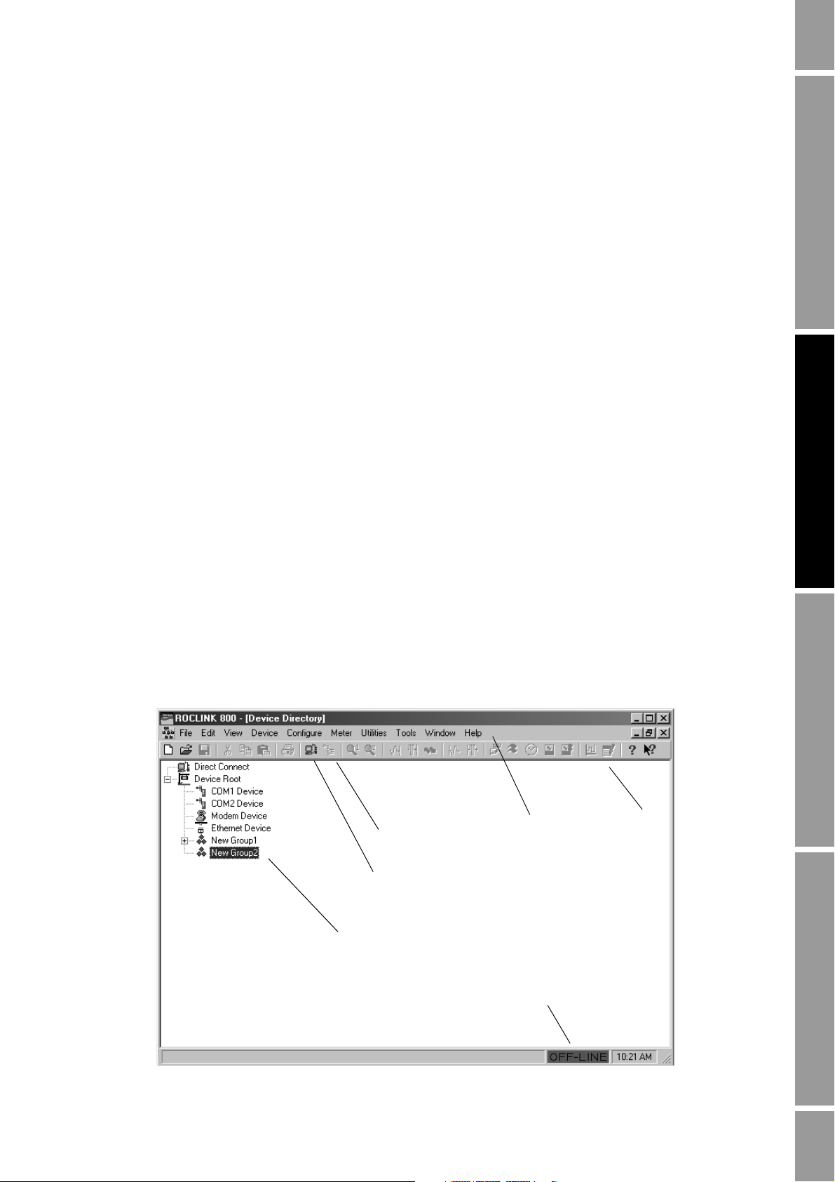
Upon successful login, the Device Directory window, shown in Figure 2-2, is displayed.
Figure 2-2 Device Directory window
Menu bar
Connect icon
Direct Connect icon
Toolbar
Device directory
Connection indicator
Configuration and Use Manual 7
Page 16

Getting Started
ROCLINK 800 uses a standard Windows interface. Use standard Windows techniques to open and
close windows and dialog boxes, expand and hide options, etc.
ROCLINK 800 windows
ROCLINK 800 windows can be maximized, minimized, or resized, using the standard Windows
controls.
In addition, the Windows menu lists all windows that are currently open, and allows you to arrange
them on the screen or bring a specific window to the top. Figure 2-3 shows ROCLINK 800 with three
windows open and cascaded.
Figure 2-3 Cascaded windows
8 Micro Motion® Model 3711 Gas Flow Computers
Page 17

Getting Started
ROCLINK 800 buttons
Several buttons are used to manage the ROCLINK 800 interface or data exchange with the
Model 3711 component. They do not interact with the core processor component. These buttons are
found on many ROCLINK 800 windows and dialog boxes (see Figure 2-4):
•
OK – Closes the current window or dialog box. If there are any unsaved changes on the screen,
a popup is displayed, asking the user if the changes should be saved to the Model 3711
configuration.
Apply – Writes the configuration parameters that are currently shown on the ROCLINK 800
•
display to the Model 3711 configuration.
•
Cancel – Closes the current window or dialog box without changing any parameters, and
without displaying a confirmation popup.
•
Update – Updates the display from current values in the Model 3711.
•
Auto Scan and Stop Scan – Enables and disables the Auto Scan feature. Auto Scan
automatically updates the display from the Model 3711, at configured intervals. See
Section 3.5 for information on configuring the Auto Scan interval.
Getting Started CommunicationsSystemBefore You Begin
If Auto Scan is not enabled, it may be useful to click
Apply, then click Update, so that the screen
displays the results of your actions.
Figure 2-4 Common buttons
Two additional buttons – the
Write Config and Read Config buttons – manage data exchange with
the core processor component as well as the Model 3711 component:
•The
Write Config Data button writes the displayed configuration parameters to the core
processor. If you have changed a parameter in ROCLINK 800, but not written it to the
Model 3711, a popup is displayed to allow you to save the change to the Model 3711.
- If you click
Yes, the change is saved to the Model 3711, and then written to the core
processor.
- If you click
No, the change is discarded and nothing is written to the Model 3711 or the
core processor.
•The
Read Config Data button reads configuration parameters from the core processor and
updates the ROCLINK 800 display. If you have changed a parameter in ROCLINK 800 but
not written it to the Model 3711, a popup is displayed to allow you to save the change.
- If you click
Yes, the change is written to the Model 3711 and the core processor before
values are read back to the display.
- If you click
No, the change is discarded and the existing values in the core processor are
read back to the display.
These buttons appear only on the Mass Flow, Density, and Temperature panels (see Section 5.4).
Note: The core processor is the component which provides preprocessing of the sensor data. In the
Model 3711 system, ROCLINK 800 communicates with the Model 3711 component, which in turn
communicates with the core processor component, which communicates with the sensor.
Configuration and Use Manual 9
Page 18
Getting Started
2.4.3 TLP system
Particular locations, or “points,” in Model 3711 memory are identified using a TLP system, where:
For example, a TLP value of
output associated with point B3 in the Model 3711’s physical memory.
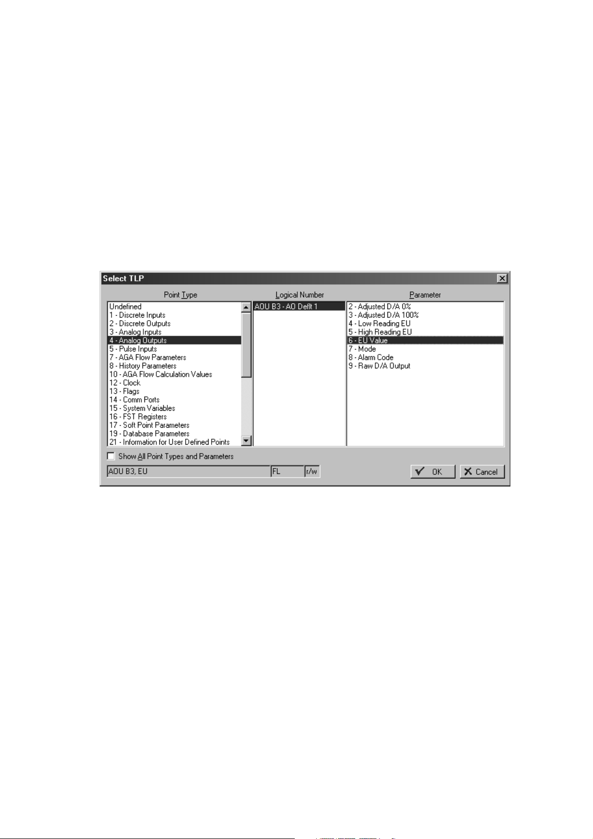
ROCLINK 800 uses the TLP system during configuration. When the TLP symbol (an ellipsis, or
displayed on a button, the button provides access to the Select TLP dialog box, shown in Figure 2-5.
Figure 2-5 Select TLP dialog box
•T = Type
• L = Logical number
•P = Parameter
AOU B3, EU represents the value, in engineering units, of the analog
...) is
TLP notation can be text, as shown here, or numeric. For example, if numeric notation is configured,
AOU B3, EU will be represented as 4 18, 6. See Section 3.5 for information on configuring TLP
notation.
To use the Select TLP dialog box:
1. Highlight the point type of the desired point.
2. Highlight the logical number of the desired point.
3. Highlight the desired parameter associated with the specified point.
See Appendix C for additional information on points and the TLP system.
10 Micro Motion® Model 3711 Gas Flow Computers
Page 19

Getting Started
2.5 Configuration files
When using ROCLINK 800 to configure the Model 3711, two types of configuration files are
involved:
• The ROCLINK 800 configuration file is specific to each installation of ROCLINK 800 on a
PC. It is created automatically, and automatically saved to a file each time that ROCLINK 800
is closed. It contains device and group definitions (see Section 2.6), and other items that are
specific to the ROCLINK 800 software, rather than to a device. No user actions are required to
create and maintain the ROCLINK 800 configuration file.
• A device configuration file is a set of operating parameters that are defined in ROCLINK 800,
then applied or downloaded to the Model 3711. Multiple device configuration files may be
defined in ROCLINK 800, and stored as files on the PC; however, only one device
configuration file can be loaded into the Model 3711 at any one time. A device configuration
file must be specifically created and saved by the user.
2.5.1 Managing device configuration files
The ROCLINK 800 File menu is used to open and close device configuration files within
ROCLINK 800, and to save a device configuration file to the PC. The File menu is also used to print a
device configuration file (see Section 14.11) and to download a device configuration file into the
Model 3711 (see Section 14.10.3).
All device configuration files use the .800 extension. You can create as many device configuration
files as you need. Each device configuration file contains information describing one Model 3711,
including its interaction with the sensor, its I/O configuration, its history setup, and so on.
Note: If you use this installation of ROCLINK 800 to interact with other devices, including
non–Model 3711 devices, their device configuration files will also use the .800 extension. Be sure to
name the device configuration files so that you will be able to identify the device and device type.
Only one device configuration file can be loaded to a Model 3711. However, multiple device
configuration files can be open within ROCLINK 800 at one time. Each device configuration file
displayed in a separate Configuration Tree window. The Window menu can be used to select the
device configuration file that you want to view or use.
Saving a device configuration file to the PC is not the same as saving it to flash memory in the
Model 3711. To save a device configuration to flash memory, click
Save Configuration
. The configuration data in flash memory is used in all cold restarts, and may be
Device > Flags >
used in warm restarts. For more information on flash memory and restart options, see Section 14.2.
Getting Started CommunicationsSystemBefore You Begin
2.5.2 Creating a new device configuration file
You do not have to be connected to a Model 3711 to create a device configuration file. However, you
will need to be connected to a Model 3711 to configure many of the properties that are saved in a
device configuration file.
To create a new device configuration file:
1. Click
2. In the upper left corner of the New Configuration File window, set
Configuration and Use Manual 11
File > New.
Configuration Type to
FB104/3711. The shown in Figure 2-6 is displayed.
Page 20

Getting Started
Figure 2-6 New Configuration File dialog box
3. Specify your I/O type.
• If your Model 3711 was ordered without the optional 6-point I/O expansion termination
board, select
6-point no I/O.
• If your Model 3711 was ordered with the optional 6-point I/O expansion termination
board, select
4. If you specified
6-point with I/O.
6-point with I/O, an External I/O frame is displayed. Use the options in this
frame to specify how five of the six I/O channels will be used (the sixth channel is always used
as a discrete output). The I/O types specified here must be compatible with the I/O wiring and
switches (see the Model 3711 installation manual for wiring instructions). You can change
these specifications later (see Section 7.3).
5. Specify the number of PID control loops that will be configured for this Model 3711. The
maximum value is 1. This value can be changed later. See Chapter 10 for more information.
6. Specify the maximum number of history points to be used for standard history and extended
history. If you add history points later, you will lose all existing history, so make sure that the
number specified will be sufficient for your Model 3711. See Chapter 8 for more information
about history.
7. Click
8. Specify a name and location to be used for the configuration file, and click
Start.
Save. All
ROCLINK 800 configuration files use the .800 extension.
9. If you want to continue with configuration, open the file when prompted. If you will perform
configuration later, close the file.
12 Micro Motion® Model 3711 Gas Flow Computers
Page 21

Getting Started
2.5.3 Device configuration backup and duplication
Once a device configuration file has been saved to your PC, it can be downloaded to any Model 3711.
This feature allows you to replicate a configuration across multiple Model 3711 installations. When
downloading, you can select specific types of configuration data as required (see Section 14.10.3).
2.6 Setting up devices and groups
Each Model 3711 is a ROCLINK 800 device. All ROCLINK 800 devices can be organized into
groups. Typically, a group contains all Model 3711 devices within one geographical area.
You do not need to be connected to a Model 3711 to add devices or groups. Device and group
definitions are stored within ROCLINK 800.
The Device Directory window (see Figure 2-2) shows the predefined entities. To open the Device
Directory window, click
Window > Device Directory or View > Directory.
Add the appropriate groups and devices for all Model 3711 devices that you will connect to from this
ROCLINK 800 installation.
Getting Started CommunicationsSystemBefore You Begin
• Right-click on
Device Root to:
- Add a device in Device Root
- Add a group in Device Root
- Delete all devices in Device Root
• Right-click on a group name to:
- Add a device to the current group
- Add a group within the current group
- Delete the current group (including all lower-level groups and devices)
- Delete all devices in the current group
- Rename the current group
• Right-click on a device name to:
- Set properties for the current device
- Rename the current device
- Delete the current device
2.7 First connection to the Model 3711
The first connection to the Model 3711 must be made through the Local Operator Interface (LOI)
port, so that default settings can be used. The LOI port always responds to connection requests made
to Device Address
240, Device Group 240. The Direct Connect function uses these default settings.
This connection can be used to configure address information, baud rate, etc., for use with subsequent
connections. For information on configuring communications, see Chapter 4.
To make the first connection to the Model 3711:
1. Ensure that the LOI cable from the Model 3711 is correctly wired to your PC (see the
Model 3711 installation manual).
Configuration and Use Manual 13
Page 22

Getting Started
CAUTION
Removing the termination board cover in hazardous environments could
result in personal injury or property damage.
Any procedure that requires removal of the enclosure end caps must be performed
only in an area known to be non-hazardous. Performance of these procedures in a
hazardous area could result in personal injury or property damage.
2. Ensure that the COM port on the PC is configured for 8 data bits.
3. Ensure that the Model 3711 is powered up.
4. Click the
Direct Connect
Direct Connect icon in the toolbar (see Figure 2-2), or click Device >
.
ROCLINK 800 makes connection attempts, beginning with COM port 1 on the PC at baud rates
between 1200 and 19.2K. It works through all COM ports on the PC, at all baud rates, until the
connection attempt succeeds.
When a successful connection is made, ROCLINK 800 displays the Configuration Tree window (see
Figure 2-7). This window displays data from the currently connected Model 3711.
Figure 2-7 Configuration Tree window
Close ROCLINK 800
Disconnect from device
2.7.1 Disconnecting and closing
To disconnect from the Model 3711, close the Configuration Tree window by clicking on the
upper right corner of the window (see Figure 2-7), or by clicking
To close ROCLINK 800, either click on the
File > Exit.
14 Micro Motion® Model 3711 Gas Flow Computers
X in the upper right corner of the main window, or click
File > Close.
X in the
Page 23

Chapter 3
System Configuration
3.1 Overview
This chapter discusses the following topics:
• Setting the Model 3711 clock
• Configuring security
• Configuring device information
• Configuring the Auto Scan interval
• Configuring TLP display options
Note: During the configuration process, save your data frequently, both to the PC and to the
Model 3711’s flash memory. To save your data to a file, click File > Save Configuration. To save your
data to flash memory, click Device > Flags > Save Configuration. For information on flash memory,
see Section 14.3.
Getting Started CommunicationsSystemBefore You Begin
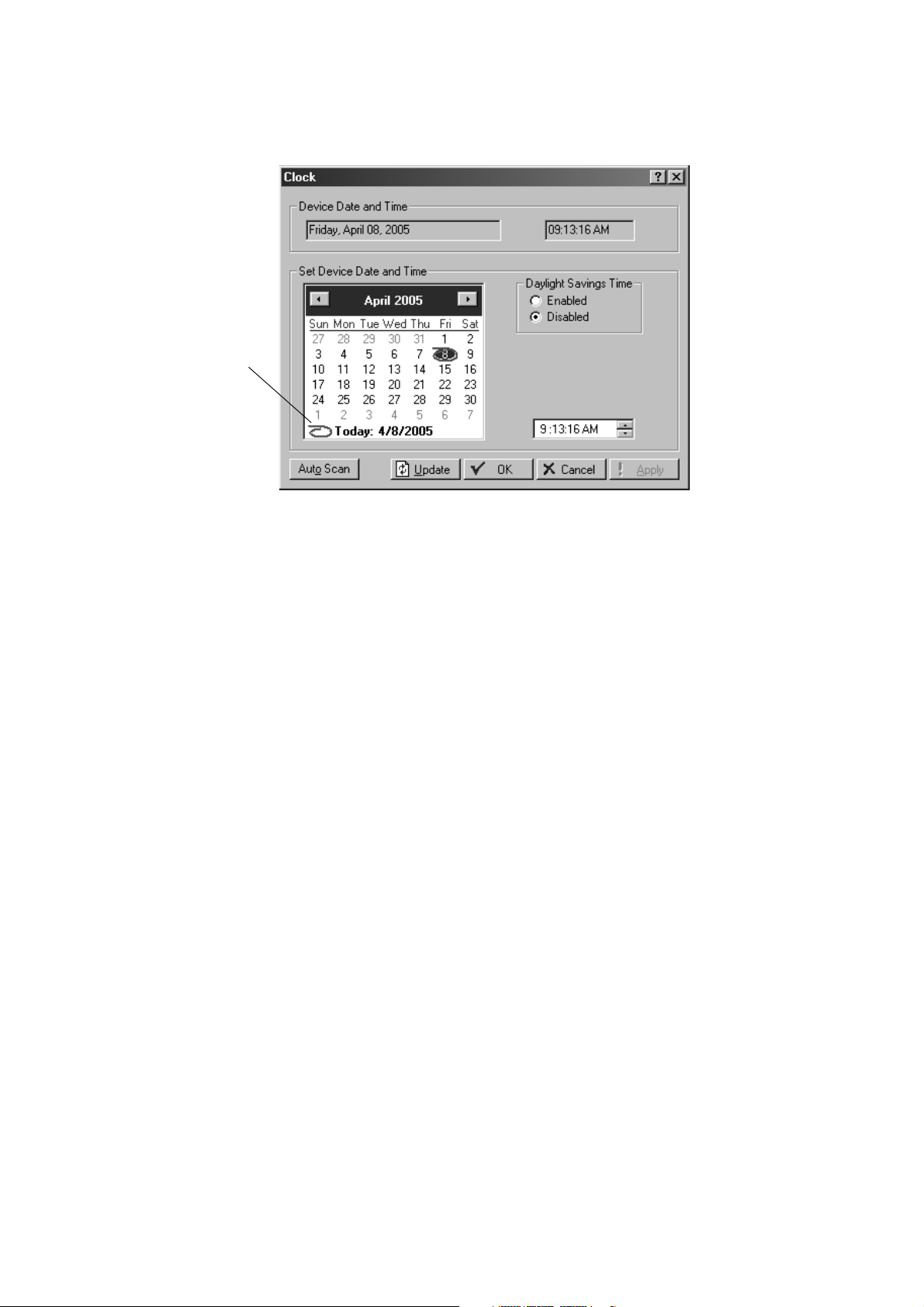
3.2 Setting the Model 3711 clock
Setting the Model 3711 clock is required for accurate timestamping and control of the historical
databases, event log, and alarm log.
To set the Model 3711 clock:
1. Connect to the Model 3711.
2. Click
3. If the clock in your PC is set correctly, click the red circle in the lower left corner of the
4. If you want the clock in the Model 3711 to automatically adjust for daylight savings time,
5. Click
6. Click
7. Click
Device > Clock, or click the Clock icon in the toolbar. The dialog box shown in
Figure 3-1 is displayed.
calendar to synchronize the Model 3711 clock to the PC clock. If the clock in your PC is not
set correctly, use the ROCLINK 800 calendar to select the day, month, and year. Then enter the
time in the time field, or use the arrows. Use
click
Enabled.
Apply.
Update to update the ROCLINK 800 screen to the current Model 3711 value.
OK.
A and P for AM and PM.
Configuration and Use Manual 15
Page 24
System Configuration
Figure 3-1 Clock dialog box
Red circle
3.3 Configuring security
Using ROCLINK 800 with the Model 3711 requires two types of security:
• Access to the ROCLINK 800 software (ROCLINK 800 security)
• Access to the COM ports on the Model 3711 (device security)
The ROCLINK 800 operator ID and password are required when you start the ROCLINK 800
program. The Model 3711 device operator ID and password are required when you connect to the
Model 3711 if device security is enabled on the com port that you are using.
3.3.1 ROCLINK 800 security
Up to 21 ROCLINK 800 operator IDs may be defined. To define a ROCLINK 800 operator ID:
1. Click
Utilities > ROCLINK 800 Security. The dialog box shown in Figure 3-2 is displayed,
showing the default operator ID and password. This operator ID is used for initial setup of the
Model 3711.
Note: Access level 5 is required to open the ROCLINK 800 Security dialog box. If you want to change
security settings after initial setup is complete, you must use an operator ID with this access level.
16 Micro Motion® Model 3711 Gas Flow Computers
Page 25

System Configuration
Figure 3-2 ROCLINK 800 Security dialog box
Getting Started CommunicationsSystemBefore You Begin
2. To add an operator ID:
a. Enter a 1–3 character value in the
Operator ID column. Any alphanumeric character may
be used. All operator IDs must be unique on this ROCLINK 800 installation. The field is
case-sensitive.
b. Enter a 1–4 character value in the
Password column. Only numeric characters may be
used. Passwords do not have to be unique.
c. Enter the access level to be assigned to this operator ID. See Section 3.3.3.
3. When all desired operator IDs have been defined, click
Save.
Note: You cannot save an operator ID without a password, or a password without an operator ID.
You can save an operator ID and password without an access level.
4. To delete an operator ID, password, or access level, highlight the cell and press
Delete, or
backspace over the value.
Note: For security reasons, Micro Motion recommends that the default operator ID be deleted after
appropriate administrative operator IDs have been defined.
3.3.2 Device security
You can enable or disable device security for the LOI and for COM1 and COM2. For each comm
port, you can enable security by operator ID or by access level.
The operator ID and password used to login to ROCLINK 800 will automatically be used for the
Model 3711 login attempt. Therefore, for each ROCLINK 800 operator ID which will be used to
access the Model 3711, define a matching Model 3711 operator ID. Up to 16 Model 3711 operator
IDs may be defined.
Configuration and Use Manual 17
Page 26
System Configuration
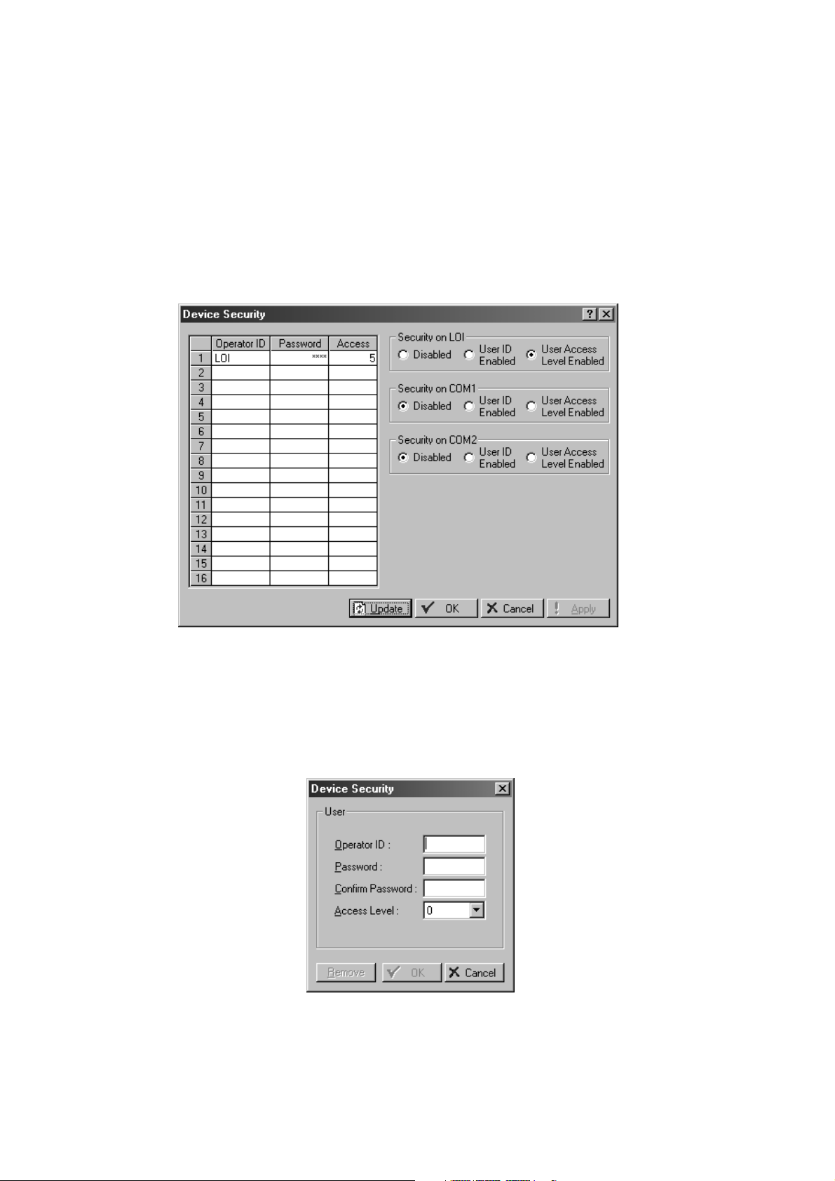
To manage device security:
1. Connect to the Model 3711.
2. Click
showing the default operator ID. Passwords are concealed. The default password is
Note: Access level 5 is required to open the Device Security dialog box. If you want to change security
settings after initial setup is complete, you must use an operator ID with this access level.
Figure 3-3 Device Security dialog box
Device > Security. The Device Security dialog box shown in Figure 3-3 is displayed,
1000.
3. To add an operator ID:
a. Click on any empty cell in the table. The Device Security popup will be displayed (see
Figure 3-4).
Figure 3-4 Device Security popup
18 Micro Motion® Model 3711 Gas Flow Computers
Page 27

System Configuration
b. Enter values as required.
c. Click
4. To edit an entry, click on any cell in that entry. Using the Device Security popup, edit the
values and click
5. To remove an entry, click on any cell in that entry. Using the Device Security popup, click
Remove.
6. To enable or disable security for LOI, COM 1, and COM 2, click the radio button for the type
of security to be enforced:
•
•
• The operator ID must be a 1–3 character value. Any alphanumeric character may be
used. The operator ID should be unique; however, no check is performed. The field is
case-sensitive.
• The password must be a 1–4 character value. Only numeric characters may be used.
The password does not have to be unique.
• See Section 3.3.3 for information about access level.
OK.
OK.
Getting Started CommunicationsSystemBefore You Begin
Disabled – All login requests are accepted.
User ID Enabled – Login requests are accepted if the operator ID and password are valid
on the Model 3711. Upon successful login, full access is allowed to all ROCLINK 800
screens and functions.
•
User Access Level Enabled – Login requests are accepted only if both of the following
are true:
- The operator ID and password are valid.
- The access level of the Model 3711 operator ID is equal to or higher than the access
level of the ROCLINK 800 operator ID.
Upon successful login, the access level of the ROCLINK 800 operator ID and the
Model 3711 operator ID are compared, and the user is limited to the lower access level.
Note: If security is enabled on any port, at least one user must be defined with access level 5.
3.3.3 Access level
For each operator ID, an access level is specified. The access levels control access to specific
ROCLINK 800 screens. Both ROCLINK 800 security and Model 3711 security use access levels.
Any access level implicitly includes all lower access levels; i.e., if access level 3 has been assigned to
an operator ID, that operator ID can also perform all actions that require access level 1 or 2.
Table 3-1 lists the ROCLINK 800 screens and the required access levels.
Configuration and Use Manual 19
Page 28

System Configuration
Tabl e 3-1 Access levels for ROCLINK 800 security and device security
Menu Option Access level required
File New 3
Edit All 0
View Directory 0
Device Direct Connect 0
Configure All 3
Meter All 2
Open 1
Download 3
Close 2
Save Configuration 3
Print Configuration 1
Print Setup 0
Recent Files 0
Exit 1
EFM Report 3
Calibration Report 2
History > From ROC 2
History > From File 1
History > Between Dates 1
Alarms > From ROC 2
Alarms > From File 1
Events > From ROC 2
Events > From File 1
Audit Log > From ROC 1
Audit Log > From File 1
Display > New 3
Display > Display 1 0
Display > Display 2 0
Display > From File 0
I/O Monitor 2
Toolbar 0
Connect 0
Collect Data 2
Clock 3
Security 5
Comm Ports 3
Memory 1
ROC Information 3
ROC Flags 3
20 Micro Motion® Model 3711 Gas Flow Computers
Page 29

System Configuration
Tabl e 3-1 Access levels for ROCLINK 800 security and device security continued
Menu Option Access level required
Utilities Upgrade Firmware 4
Tools Customize 0
Window All 0
Help All 0
Upgrade Hardware 4
Upgrade to FlashPAC 4
License Key Administrator 5
Convert EFM File 3
User Program Administrator 4
ROCLINK Security 5
AI Calibration Values 3
RTD Calibration Values 3
MVS Calibration Values 3
FST Editor 3
Debug Communications 0
Options 3
Getting Started CommunicationsSystemBefore You Begin
3.4 Configuring Model 3711 device information
Model 3711 device information includes Model 3711 address information and several other types of
information.
To configure device information parameters:
1. Click
Device > Information. The Device Information dialog box shown in Figure 3-5 is
displayed.
Configuration and Use Manual 21
Page 30
System Configuration
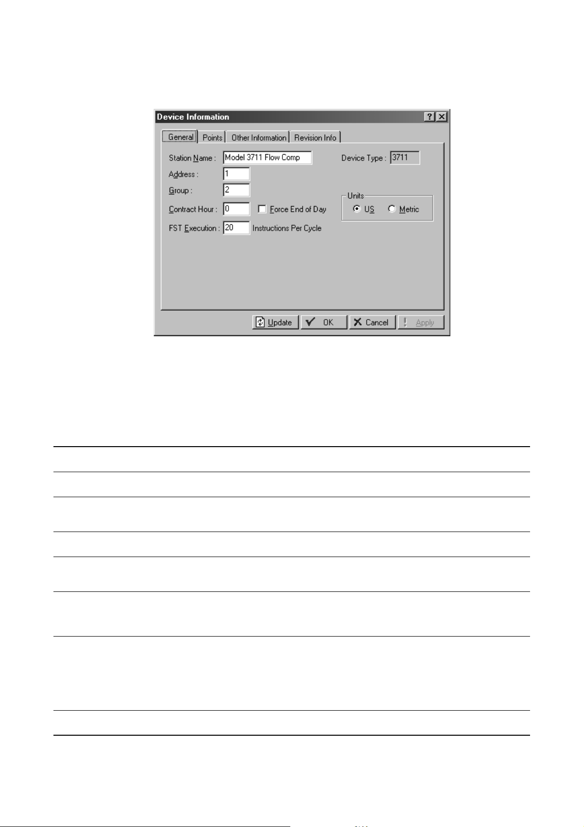
Figure 3-5 Device Information dialog box
2. On the General tab, configure parameters as required. Parameters are listed and defined in
Tabl e 3 -2 .
Tabl e 3-2 Device Information dialog box – General panel
Parameter Description Comments
Station Name Name of this Model 3711 Corresponds to Tag value in Communication
Properties dialog box
Address Address to be assigned to this Model 3711.
This value must be unique within the group.
Group Group to which this Model 3711 belongs. A
group typically describes a set of devices in
the same geographical area.
Device Type Read-only. Displays the device type of the
Model 3711.
Contract Hour Time at which values are totaled for a
single day of production and data is logged
to Daily History database
Force End of Day Current day and hourly values will be
logged into memory for all historical data
except station totals. Resets daily and
hourly accumulators.
FST Execution Controls the number of FST instructions to
be executed during one FST execution
period (one second). See Section 11.2.
Units Controls the type of unit used for display
and for calculations.
Corresponds to Device address value in
Communication Parameters dialog box
Corresponds to Device group value in Communication
Parameters dialog box, and to Group number in Device
Directory window
Uses one of the 35 available slots in the standard
history database.
Default: 20. Range: 1–100.
Changes to this parameter take effect in the next FST
execution period. Restart is not required.
To reduce the risk of overloading the Model 3711,
monitor the MPU (Micro Processor Unit) loading when
changes to this parameter are made. See
Section 15.7.
Enter all values in units appropriate to the system of
units specified here.
22 Micro Motion® Model 3711 Gas Flow Computers
Page 31

System Configuration
3. If you will configure a PID control loop on this Model 3711, open the Points panel and set the
Active PIDs value to 1. See Chapter 10 for more information.
Note: The Other Information and Revision Information panels contain read-only information
describing the Model 3711 hardware, software, purchase, and so on. No user configuration is
required.
4. Click
Apply, then click OK.
3.5 Configuring display options
The display options are used to specify:
• TLP notation: text or numbers (see Section 2.4.3 for a discussion of the TLP system)
• The Auto Scan interval (see Section 2.4.2 for information on the Auto Scan feature)
To configure the display options:
1. Click
Tools > Options. The dialog box shown in Figure 3-6 is displayed.
Figure 3-6 Options dialog box
Getting Started CommunicationsSystemBefore You Begin
2. Click the
Display TLP radio button to specify the TLP display type.
3. Enter the number of seconds to be used between auto scans. The minimum value is
0.001 seconds.
Note: The smaller the Auto Scan interval, the greater the load on the processor and on
communications. Do not set the Auto Scan interval to a value smaller than required by your
application.
Note: Setting the Auto Scan interval does not enable Auto Scan. To enable Auto Scan, you must click
the Auto Scan button (see Section 2.4.2).
Configuration and Use Manual 23
Page 32

24 Micro Motion® Model 3711 Gas Flow Computers
Page 33

Chapter 4
Setting Up Communications
4.1 Overview
This chapter describes:
• Connecting to the Model 3711 through the LOI
• Connecting to the Model 3711 through COMM 2
• Configuring communications parameters
- Configuring COMM 2 on the Model 3711
- Configuring ROCLINK 800 communications parameters
• Configuring Report By Exception (RBX) alarming
• Configuring passthrough mode
Getting Started CommunicationsSystemBefore You Begin
4.2 Communications overview
The Model 3711 has three communication ports:
• The Local Operator Interface (LOI) port
• COMM 1 – dedicated to communication with the Micro Motion sensor, and cannot be used for
other communication. Do not configure COMM 1.
• COMM 2 – may be either a serial communications card or a dial-up modem card.
The LOI supports only ROC protocol. COMM 2 supports both Modbus and ROC protocol.
ROCLINK 800 uses ROC protocol. A host program can use either Modbus or ROC protocol.
COMM 2 auto-detects and responds to both protocols.
In a typical installation:
• ROCLINK 800 is used to configure the Model 3711, and to perform administration and field
service tasks. ROCLINK 800 may also be used to collect history data. The ROCLINK 800
connection is typically made through the LOI, using the Direct Connect function.
• A host program is used to collect history, event, and alarm data. The host program typically
connects via COMM 2.
ROCLINK 800 provides two connection types:
• Direct Connect – ROCLINK 800 makes multiple connection attempts, using the values of
Device Address
with COM port 1 on the PC and works through all COM ports, at all baud rates, until a
connection attempt succeeds.
240, Device Group 240, and baud rates between 1200 and 19.2K. It begins
• Connect – ROCLINK 800 makes a connection attempt to the specified device, using the
ROCLINK 800 communications parameters configured for that device (Section 4.5.2).
Configuration and Use Manual 25
Page 34

Setting Up Communications
Both functions can be used to connect through either the LOI or COMM 2. If the ROCLINK 800
platform is wired directly to the Model 3711, either the Direct Connect or the Connect function can be
used. On a multidrop network, the Connect function must be used to specifically identify the
Model 3711.
A host program will typically emulate the Connect function.
4.3 Connecting to the Model 3711 through the LOI
Before attempting to connect through the LOI port on the Model 3711, ensure that the LOI cable from
the Model 3711 is correctly installed with your PC or host device. See the Model 3711 installation
manual.
The LOI always responds to both of the following:
• All connection requests made to Device Address
• All connection requests made to the device address and device group configured for the
Model 3711 in the Device Information dialog box (see Section 3.4)
To connect through the LOI using the Direct Connect function in ROCLINK 800, you can use any of
the following methods:
240, Device Group 240
• Clicking the
• Clicking
Direct Connect icon in the toolbar
Device > Direct Connect
• Right-clicking Direct Connect in the Device Directory window, then clicking Connect
4.4 Connecting to the Model 3711 through COMM 2
Before attempting to connect through COMM 2 on the Model 3711, ensure that:
• The communications wiring from the Model 3711 is correctly installed with your PC or host
device. See the Model 3711 installation manual.
• The serial or dial-up modem card is correctly configured. See Section 4.5.1.
COMM 2 always responds to both of the following:
• All connection requests made to Device Address
• All connection requests made to the device address and device group configured for the
Model 3711 in the Device Information dialog box (see Section 3.4)
4.4.1 Using ROCLINK 800
To connect through COMM 2 using the Connect function in ROCLINK 800, you must configure the
ROCLINK 800 communication parameters appropriately for the specific Model 3711 unit (see
Section 4.5.2).
• If you are making a point-to-point connection, you can use the configured device address and
device group or the default values.
• If you are connecting over a multidrop network, you must use the configured device address
and device group.
Then use one of the following methods:
• Clicking the
Connect icon in the toolbar
240, Device Group 240
• Clicking
Device > Connect
• Right-clicking the Model 3711 device in the Device Directoy window, then clicking Connect
26 Micro Motion® Model 3711 Gas Flow Computers
Page 35

Setting Up Communications
Note: ROCLINK 800 always uses ROC protocol to connect to the Model 3711. ROC protocol always
uses 8 data bits, 1 stop bit, and no parity. If you are having trouble connecting, ensure that the COM
port on your PC is configured for 8 data bits. ROCLINK 800 auto-adjusts the other PC COM port
settings as required.
4.4.2 Using a host program
If a host program will connect through COMM 2, it must use the same connection parameters that
ROCLINK 800 uses (see Section 4.4.1).
4.5 Configuring communications parameters
You may need to configure one or more of the following, depending on the communications methods
that you will use:
• COMM 2 on the Model 3711 (used with the serial communications or dial-up modem card)
• ROCLINK 800 communications parameters (required if the Connect function will be used)
4.5.1 Configuring COMM 2 on the Model 3711
If you will connect to the Model 3711 through COMM 2, using either the serial communications card
or the dial-up modem card, you must configure COMM 2 on the Model 3711. To do this:
1. Connect to the Model 3711 using the LOI.
2. Click
3. Select
Device > Comm Ports. The Comm Port dialog box shown in Figure 4-1 is displayed.
3 - Comm2 from the Comm Ports dropdown list.
4. Enter a tag, if desired.
Figure 4-1 Comm Port dialog box – General panel
Getting Started CommunicationsSystemBefore You Begin Getting Started CommunicationsSystemBefore You Begin Getting Started CommunicationsSystemBefore You Begin Getting Started CommunicationsSystemBefore You Begin
Configuration and Use Manual 27
Page 36

Setting Up Communications
5. On the General panel, configure parameters as required (see Table 4-1). Parameters set here
apply to both the serial communications card and the dial-up modem card.
Tabl e 4-1 Comm Port – General panel
Parameter Description Comments
Baud Rate Send and receive bits per second The PC COM port must be
configured to match this setting.
• ROCLINK 800 automatically
adjusts the PC COM port to
match this setting.
• Other hosts may or may not
auto-adjust.
Parity Type of parity check to be performed The PC COM port must be
Data Bits • 7 (used by Modbus ASCII)
• 8 (used by Modbus RTU and ROC protocol)
Stop Bits Number of stop bits in each character The PC COM port must be
Key On Delay Specify the number of seconds that will elapse between the
Key Off Delay Specify the number of seconds that will elapse between the
Valid Receive
Counter
Idle Time Specify the number of milliseconds that the Model 3711 will
time that the RTS signal is turned on and the time that message
transmission begins.
time that message transmission is finished and the time that the
RTS signal is turned off.
Displays the number of valid messages that have been received
by this port.
delay, after receipt of the last character, before beginning
processing.
configured to match this setting.
• ROCLINK 800 automatically
adjusts the PC COM port to
match this setting.
• Other hosts may or may not
auto-adjust.
Must match the value configured
for the PC COM port.
• ROCLINK 800 always uses 8
data bits, and does not
auto-adjust the PC COM port.
• Other hosts may require either 7
or 8 data bits.
configured to match this setting.
• ROCLINK 800 automatically
adjusts the PC COM port to
match this setting.
• Other hosts may or may not
auto-adjust.
Set to 0 initially, then add delay as
required.
Set to 0 initially, then add delay as
required.
May be reset to 0 or any other
desired start value.
6. If you are configuring the dial-up modem card:
a. Click the
b.
Modem Type is automatically set to Internal.
Modem tab. The Modem panel is displayed (see Figure 4-2).
Note: You may also use an external modem. In this case, set Modem Type to External and configure
all other parameters as required.
c. Set other parameters as required. Modem parameters are listed and defined in Table 4-2.
28 Micro Motion® Model 3711 Gas Flow Computers
Page 37

Setting Up Communications
Figure 4-2 Comm Ports window, Modem panel
Getting Started CommunicationsSystemBefore You Begin Getting Started CommunicationsSystemBefore You Begin Getting Started CommunicationsSystemBefore You Begin Getting Started CommunicationsSystemBefore You Begin
Tabl e 4-2 Comm Port – Modem panel
Parameter Description Comments
Connect Time Enter the number of seconds that the Model 3711 will wait, after
initiating a call, to receive a connect message from the remote
device.
• If the connection is successful, the Disconnect Time period
begins.
• If the connection is not successful, additional connection
attempts are made as configured in the RBX panel (see
Section 4.6).
Disconnect Time Enter the number of seconds that the Model 3711 will wait for
Inactivity Time Enter the number of seconds that the Model 3711 will wait,
Config Command Enter the characters required to initialize the modem. If you are using the dial-up modem
Connect
Command
Modem Status Displays current modem status. Read-only.
further activity on the line, before it hangs up the connection.
without receiving a signal, before it resets the modem.
Enter the command required to contact the host. For the dial-up modem card, use a
The modem will initiate a call only
if RBX alarming is enabled (see
Section 4.6) or the port is used as
the sending port in passthrough
mode (see Section 4.7).
In a typical installation,
approximately 60 seconds are
required to make and complete a
dial-up connection.
This timer is reset after each valid
receive signal.
The Valid Receive Counter is used
to determine if the signal has been
received.
card, the default value is required.
value like the following:
ATDT13031234567
If you are using an external
modem, see the command
documentation for your modem.
Configuration and Use Manual 29
Page 38

Setting Up Communications
4.5.2 Configuring ROCLINK 800 communications parameters
If you will connect to the Model 3711 using the Connect function, ROCLINK 800 communications
parameters must be configured. Because ROCLINK 800 can be used to connect to multiple devices,
communications parameters are saved separately for each device.
Note: PC COM port parameters are automatically adjusted by ROCLINK 800 as required.
To configure ROCLINK 800 communications parameters for the Model 3711:
1. Start ROCLINK 800 software, but do not connect to a device.
2. Using the Device Directory window in ROCLINK 800 (see Figure 2-2), right-click the device
defined for your Model 3711 (see Section 2.6), then click
Communication Parameters dialog box shown in Figure 4-3 is displayed.
Figure 4-3 ROCLINK 800 Communication Parameters dialog box – General panel
Properties. The ROCLINK 800
3. In the General panel, set connection parameters as required (see Table 4-3). Note:
•
Tag, Device Address, and Device Group identify the Model 3711 that you are
connecting to. The values entered here must match the values configured for the
Model 3711 in the Device Information dialog box (see Section 3.4).
•
Host Address and Host Group will be used by the Model 3711 to identify this host when
formatting responses to requests.
30 Micro Motion® Model 3711 Gas Flow Computers
Page 39

Setting Up Communications
Tabl e 4-3 ROCLINK 800 Communication Parameters – General panel
Model 3711
Parameter Description ROCLINK 800 Default
Tag Model 3711 station name device name Model 3711
Device Address A unique value within the device group 240 1
Device Group The group that the Model 3711 belongs to 240 2
Host Address A unique value within the host group 3 N/A
Host Group The group that the PC running ROCLINK 800
belongs to
Use Type of connection Comm port N/A
PC Comm Port COM port that the PC will use to communicate
with the Model 3711
Baud Rate Connection speed 9600 N/A
1N/A
1N/A
Default
4. Click Apply.
5. To set advanced communication properties, click the
Advanced tab. The panel shown in
Figure 4-4 is displayed.
Getting Started CommunicationsSystemBefore You Begin Getting Started CommunicationsSystemBefore You Begin Getting Started CommunicationsSystemBefore You Begin Getting Started CommunicationsSystemBefore You Begin
Figure 4-4 Communication Parameters dialog box – Advanced panel
Configuration and Use Manual 31
Page 40

Setting Up Communications
6. In the Advanced panel, set connection parameters as desired (see Table 4-4).
Tabl e 4-4 ROCLINK 800 Communication Parameters – Advanced panel
Parameter Description Comments
Number of
Retries
Time Out Specify the number of seconds that ROCLINK 800 will wait
Tx Delay Specify the number of seconds that will elapse between the
Key Off Delay Specify the number of seconds that will elapse between the
Host CRC Check • Enabled: ROCLINK 800 will apply Cyclical Redundancy
Specify the number of times that ROCLINK 800 will request
data from the Model 3711, before reporting a timeout error, if
the initial request fails.
between retries, if the initial request fails.
time the RTS line is enabled and the time that data transmission
begins.
time that message transmission is finished and the time that the
RTS signal is turned off.
Checking (CRC) error checking to messages sent and
received through this comm port.
• Disabled: ROCLINK 800 will not apply CRC error checking.
Range: 0 to 25
Do not enter 0 in this field.
A non-zero delay is required for
radio communications. For other
communications, set to 0 initially,
then add delay as required.
Set to 0 initially, then add delay as
required.
7. Click
Apply, then click OK.
4.6 Configuring communications for RBX alarming
Report By Exception (RBX) alarming can be configured for analog inputs, analog outputs, and pulse
inputs (see Chapter 7), and for flow alarms (see Section 6.5.1). If RBX alarming is enabled, the
Model 3711 will send a message through the specified comm port when an alarm occurs.
Note: It is the user’s responsibility to ensure that the comm port connects to an appropriate receiving
device.
If RBX alarming will be enabled for any of the functions listed above, a communications port must be
configured for RBX alarming. To configure a communications port for RBX alarming:
1. Connect to the Model 3711.
2. Click
Device > Comm Ports. The Comm Port dialog box shown in Figure 4-1 is displayed.
3. Use the dropdown list to select the comm port that will be used for RBX alarming.
4. Ensure that all parameters on the General panel are correctly set for this comm port (see
Table 4-1).
5. If you are using the dial-up modem for RBX alarming, ensure that all parameters on the
Modem tab are correctly set (see Table 4-2).
6. Click the
RBX tab. The panel shown in Figure 4-5 is displayed.
32 Micro Motion® Model 3711 Gas Flow Computers
Page 41

Setting Up Communications
Figure 4-5 Comm Port dialog box – RBX panel
Getting Started CommunicationsSystemBefore You Begin Getting Started CommunicationsSystemBefore You Begin Getting Started CommunicationsSystemBefore You Begin Getting Started CommunicationsSystemBefore You Begin
7. Set RBX parameters as desired (see Table 4-5).
Tabl e 4-5 Comm Port – RBX panel
Parameter Description Comments
RBX Mode • Enabled: RBX alarming can be configured and used.
• Disabled: RBX alarming will not be implemented, even if an
input or output is configured for it.
RBX Host
Address
RBX Host Group Specify the group number of the host to which the RBX alarm
RBX Attempts • Fixed Number: This attempt will be sent the specified number
Delay For each attempt, enter the number of seconds that will elapse
Extra Key on
Delay
Specify the address of the host to which the RBX alarm
messages will be sent.
messages will be sent.
of times, until the transmission is successful. If Fixed Number
is specified, enter a value for the number of retries.
• Continuous: This attempt will be sent continuously until the
host clears the RBX alarm.
between retries to send an RBX alarm message.
Enter the number of seconds to wait, after the RTS signal is
turned on, before beginning transmission of an RBX message.
This delay is added to the configured Tx Delay (see Table 4-4).
An attempt includes the initial
message plus all configured
retries.
If the retry number is set to 0, no
retries will occur.
This parameter is used only for
radio communications.
Configuration and Use Manual 33
Page 42

Setting Up Communications
Tabl e 4-5 Comm Port – RBX panel continued
Parameter Description Comments
RBX Alarm Index Displays any alarms currently being reported through the RBX
RBX Status Indicates the status of RBX message:
RBX Ack Timeout Enter the number of seconds that the Model 3711 will wait for
feature.
• Active: An RBX alarm is being processed.
• Inactive: No RBX alarm is being processed.
the host to respond to an RBX message with an ACK
(acknowledgment) message.
If no ACK is received within the
specified time, the Model 3711
continues with retry and attempt
processing.
4.7 Configuring passthrough mode
Passthrough mode allows the Model 3711 to receive a message from a host via one port (the receiving
port) and automatically retransmit the message to other devices on the network through another port
(the sending port).
For example, a Model 3711 could be set up to receive host communications through the LOI. If
passthrough from LOI to COMM 2 is configured (i.e., the LOI is the receiving port and COMM 2 is
the sending port):
• All messages received through the LOI that are addressed specifically to the passthrough
device will be processed locally, and will not be retransmitted.
• All other messages received through the LOI will be automatically retransmitted over
COMM 2.
Any device accessible via the sending port can receive the retransmitted message, depending on the
protocol used, the device group and device address specified in the message, etc.:
• If ROC protcol is used for the message, only devices in the same device group as the
Model 3711 will receive the retransmitted message.
• If Modbus protocol is used for the message, all other devices on the network will receive the
retransmitted message.
Note: Because COMM 1 is dedicated to sensor communications, only the LOI and COMM 2 can be
used when configuring passthrough mode.
Note: If COMM 2 is used as a dial-up modem, and you want to configure it for passthrough, it must
be defined as the receiving port. It cannot act as the sending port.
To set up passthrough mode:
1. Ensure that the necessary wiring is in place between the Model 3711’s sending port and all
receiving devices.
2. If ROC protocol will be used, ensure that all receiving devices are members of the same device
group (see Section 3.4).
3. At the Model 3711 which is directly connected to the host, specify the pair of ports that will be
used for passthrough mode. The Flags window, Advanced panel, is used for this configuration
(see Figure 4-6). To access the Flags window, click
34 Micro Motion® Model 3711 Gas Flow Computers
Device > Flags.
Page 43

Setting Up Communications
Figure 4-6 Flags window – Advanced panel
Getting Started CommunicationsSystemBefore You Begin Getting Started CommunicationsSystemBefore You Begin Getting Started CommunicationsSystemBefore You Begin Getting Started CommunicationsSystemBefore You Begin
Note: Other functions available on this panel are discussed in Section 14.7.
Configuration and Use Manual 35
Page 44

36 Micro Motion® Model 3711 Gas Flow Computers
Page 45

Chapter 5
Configuring the Core Interface
5.1 About this chapter
This chapter explains how to configure the interface between the Model 3711 and the Micro Motion
Coriolis sensor.
Note: The terms “core” and “core processor” refer to the component which provides preprocessing
of the sensor data. In the Model 3711 system, the Model 3711 component communicates with the core
processor component, rather than directly with the sensor.
Note: In this chapter, the word “sensor” refers to the Micro Motion Coriolis sensor which is used to
measure gas flow. Other sensors may be included in the installation, such as a pressure sensor, a
temperature sensor, and so on. Configuration of these sensors is not covered in this chapter or this
manual.
Additional information is provided on the topics of characterization, damping, meter factors, and slug
flow. Finally, the sensor zero procedure and the density calibration procedures are discussed.
Volumetric Flow Measurement History, Events, and AlarmsI/OCore Interface
5.2 Configuration overview
To access the sensor configuration panels, click
several panels is loaded. To configure the sensor interface, you must:
• Configure parameters on the Mass Flow panel
• Configure parameters on the Density panel
• Configure parameters on the Temperature panel
Note: This display provides other functions in addition to configuration. This chapter discusses only
sensor configuration. Information on other functions is provided elsewhere in this manual.
After the sensor is configured, you must perform a sensor zero (see Section 5.6).
Meter > Core Interface. A custom display containing
Configuration and Use Manual 37
Page 46

Configuring the Core Interface
5.3 Using ROCLINK 800 with the Micro Motion core interface
The flowchart in Figure 5-1 displays the recommended procedure for using ROCLINK 800 to
configure the core interface. See Section 2.4.2 for information on the function buttons, and see
Sections 14.2 and 14.3 for information on the saved configuration file and flash memory.
Figure 5-1 Configuration method flowchart
Configuration
Mass Flow / Density /
Temperature
Change parameter on screen
Write change
to Model 3711
Verify change in
Model 3711
Write parameter
to core processor
Verify change in
core processor
Apply
Update
Write Config Data
Read Config Data
5.4 Core interface configuration panels
This section describes the panels used to configure the core interface.
To access a panel, click the appropriate tab at the top of the Core Processor Interface window.
Update configuration file
File Menu >
Save Configuration
Write to flash memory
Device Menu >
Flags
Save Configuration
Done
5.4.1 Mass Flow panel
The Mass Flow panel is shown in Figure 5-2. Parameters on this panel control how the sensor will
measure and report mass flow data to the Model 3711. Parameters are listed and defined in Table 5-1.
38 Micro Motion® Model 3711 Gas Flow Computers
Page 47

Configuring the Core Interface
Figure 5-2 Mass Flow panel
Volumetric Flow Measurement History, Events, and AlarmsI/OCore Interface
Tabl e 5-1 Mass flow configuration parameters
Parameter Description Comments
Flow Direction Forward Only: Only flow in the direction defined by the flow
Damping Period The number of seconds over which the reported mass flow rate
Low Flow Cutoff The mass flow rate value below which the Model 3711 will
Flow Cal Factor
(FCF)
Configuration and Use Manual 39
arrow on the sensor is used in the calculation of flow rate and
flow totals.
will change to reflect 63% of the change in the actual process.
See Section 5.5.2.
report a value of 0 for the mass flow rate.
One of the values required to characterize the Model 3711 for
the particular sensor it is using. See Section 5.5.1.
Read-only.
Default: 3.2 seconds.
Default: 0.0.
Recommended setting: 0.5–1.0%
of the sensor’s rated maximum
flowrate
Page 48

Configuring the Core Interface
Tabl e 5-1 Mass flow configuration parameters continued
Parameter Description Comments
Flow Temp Coeff
(FT)
Meter Factor The adjustment to be applied to the mass flow process variable.
Mechanical Zero Displays the zero value derived from the most recent zero
One of the values required to characterize the Model 3711 for
the particular sensor it is using. See Section 5.5.1.
Default: 1.0
See Section 5.5.3.
Read-only.
procedure.
5.4.2 Density panel
The Density panel is shown in Figure 5-3. Parameters on this panel control how the sensor will
measure and report density data to the Model 3711. Parameters are listed and defined in Table 5-3.
Figure 5-3 Density panel
40 Micro Motion® Model 3711 Gas Flow Computers
Page 49

Configuring the Core Interface
Tabl e 5-2 Density configuration parameters
Parameter Description Comments
Damping Period The number of seconds over which the reported density value
will change to reflect 63% of the change in the actual process.
See Section 5.5.2.
Low Density
Cutoff
The density value below which the Model 3711 will report a
value of 0 for density.
Slug Duration The number of seconds the Model 3711 waits for a slug flow
condition (outside the slug flow limits) to return to normal (inside
the slug flow limits). See Section 5.5.4.
High Slug Limit The density value above which a condition of slug flow will exist.
Typically, this is the highest point in the normal density range of
the process. See Section 5.5.4.
Low Slug Limit The density value below which a condition of slug flow will exist.
Typically, this is the lowest point in the normal density range of
the process. See Section 5.5.4.
Density Meter
Factor
Flowing Density
Factor
Temperature
Coeff (DTC)
The adjustment to be applied to the density process variable.
See Section 5.5.3.
The correction factor for the effect of flow on density. Enter the
FD value stamped on the sensor tag.
One of the values required to characterize the Model 3711 for
the particular sensor it is using. On some sensor tags, this value
is shown as TC. See Section 5.5.1.
Low Density Cal
Value (D1)
Low Density Tube
Period (K1)
High Density Cal
Value (D2)
High Density
Tube Period (K2)
One of the values required to characterize the Model 3711 for
the particular sensor it is using. See Section 5.5.1.
One of the values required to characterize the Model 3711 for
the particular sensor it is using. See Section 5.5.1.
One of the values required to characterize the Model 3711 for
the particular sensor it is using. See Section 5.5.1.
One of the values required to characterize the Model 3711 for
the particular sensor it is using. See Section 5.5.1.
Default: 1.6 seconds
Default: 200 kg/m
Range: 0–5000 kg/m
(312.14 lb/ft3)
Default: 0.0 seconds
Range: 0.0–60.0 seconds
Default: 5.0 g/cm
Range: 0.0–10.0 g/cm
Use g/cm3 to configure this
parameter, even if you have
configured U.S. units.
Default: 0.0 g/cm
Range: 0.0–10.0 g/cm
Use g/cm3 to configure this
parameter, even if you have
configured U.S. units.
Default: 1.0
Default: 0.0
3
(12.48 lb/ft3)
3
3
3
3
3
Volumetric Flow Measurement History, Events, and AlarmsI/OCore Interface
5.4.3 Temperature panel
The Temperature panel is shown in Figure 5-4. Parameters on this panel control how the sensor will
measure and report temperature data to the Model 3711. Parameters are listed and defined in
Tabl e 5 -3 .
Configuration and Use Manual 41
Page 50

Configuring the Core Interface
Figure 5-4 Temperature panel
Tabl e 5-3 Temperature configuration parameters
Parameter Description Comments
Damping Period The number of seconds over which the reported temperature
Calibration Slope The slope value used to adjust the temperature process
Calibration Offset The offset value used to adjust the temperature process
External
Temperature
42 Micro Motion® Model 3711 Gas Flow Computers
value will change to reflect 63% of the change in the actual
process. See Section 5.5.2.
variable.
variable.
• Disabled: Temperature data from the Micro Motion sensor will
be used.
• Enabled: Temperature data from a different temperature
device will be used. If Enabled is specified, a Source field is
displayed. Use the Select TLP dialog box to specify the
temperature source. The Value field displays the current
temperature value from the specified source.
Default: 4.8 seconds
Default: 1.0
Default: 0.0
Applies to all Model 3711
calculations that require a
temperature value.
Page 51

Configuring the Core Interface
5.5 Special topics in configuring the core interface
This section provides additional information on characterizing the Model 3711, configuring damping,
calculating and configuring meter factors, and configuring slug flow.
5.5.1 Characterization
Characterizing the meter adjusts the Model 3711 to compensate for the unique traits of the sensor it is
paired with. The characterization parameters describe the sensor’s sensitivity to flow and density.
If the Model 3711, core processor, and sensor were ordered together, then the meter has already been
characterized. You need to characterize the meter only if the core processor and sensor are being
paired together for the first time.
The characterization parameters are provided on the sensor tag. The format of the sensor tag varies
depending on your sensor’s date of purchase. See Figure 5-5 for illustrations of newer and older
sensor tags.
Figure 5-5 Sample calibration tags
Newer tag Older tag
19.0005.13
12500142864.44
0.0010
0.9980
4.44000
Density calibration factors
12502.000
14282.000
310
Volumetric Flow Measurement History, Events, and AlarmsI/OCore Interface
19.0005.13
12500142864.44
If your sensor tag does not show a D1 or D2 value:
• For D1, enter the Dens A or D1 value from the calibration certificate. This value is the
line-condition density of the low-density calibration fluid. Micro Motion uses air.
• For D2, enter the Dens B or D2 value from the calibration certificate. This value is the
line-condition density of the high-density calibration fluid. Micro Motion uses water.
If your sensor tag does not show a K1 or K2 value:
• For K1, enter the first 5 digits of the density calibration factor. In the sample tag in Figure 5-5,
this value is shown as
12500.
• For K2, enter the second 5 digits of the density calibration factor. In the sample tag in
Figure 5-5, this value is shown as
14286.
If your sensor tag does not show an FD value, contact Micro Motion customer service.
If your sensor tag does not show a DTC or TC value, enter the last 3 digits of the density calibration
factor. In the sample tag in Figure 5-5, this value is shown as
Configuration and Use Manual 43
4.44.
Page 52

Configuring the Core Interface
Flow calibration values
Two separate values are used to describe flow calibration: a 6-character FCF value and a 4-character
FT value. Both values contain decimal points. On the sensor tags, these two values are concatenated
to form a 10-character string called Flow Cal or Flow Cal Factor (see Figure 5-5).
• For the FCF value, enter the first six characters of the string. In the sample tags in Figure 5-5,
this value is shown as
• For the FT value, enter the last four characters of the string. In the sample tags in Figure 5-5,
this value is shown as
5.5.2 Damping
You can configure damping for both mass flow measurement, density measurement, and temperature
measurement. Damping helps the transmitter smooth out small, rapid measurement fluctuations:
• A high damping value makes the output appear to be smoother because the output must change
slowly.
• A low damping value makes the output appear to be more erratic because the output changes
more quickly.
When you specify a new damping value, it is automatically rounded down to the nearest valid
damping value.
19.000.
5.13.
Valid damping values are listed in Table 5-4.
Table 5-4 Valid damping values
Process variable Valid damping values
Mass flow 0, .2, .4, .8, ... 51.2
Density 0, .2, .4, .8, ... 51.2
Temperature 0, .6, 1.2, 2.4, 4.8, ... 76.8
Note: For typical gas applications, Micro Motion recommends a flow damping value of 3.2 (the
default).
5.5.3 Meter factors
Meter factors allow you to adjust the Model 3711’s reported mass flow rate or density value to match
an external measurement standard. Meter factors are used for proving the meter against a Weights &
Measures standard. You may need to calculate and configure the meter factors periodically.
Use the following formula to calculate a meter factor:
ExternalStandard
-----------------------------------------------------------------------------------
NewMeterFactor ConfiguredMeterFactor
×=
ActualTransmitterMeasurement
44 Micro Motion® Model 3711 Gas Flow Computers
Page 53

Configuring the Core Interface
Example
The meter is installed and proved for the first time. The meter mass
measurement is 250.27 lb; the reference device measurement is 250
lb. A mass flow meter factor is determined as follows:
250
MassFlowMeterFactor 1
The first mass flow meter factor is 0.9989.
One year later, the meter is proved again. The meter mass
measurement is 250.07 lb; the reference device measurement is
250.25 lb. A new mass flow meter factor is determined as follows:
MassFlowMeterFactor 0.9989
The new mass flow meter factor is 0.9996.
------------------
× 0.9989==
250.27
250.25
------------------
× 0.9996==
250.07
5.5.4 Slug flow
Slugs – gas in a liquid process or liquid in a gas process – occasionally appear in some applications.
The presence of slugs can significantly affect the process density reading. The slug flow parameters
can help the transmitter suppress extreme changes in process variables, and can also be used to
identify process conditions that require correction.
Slug flow parameters are as follows:
• High slug limit – the point above which a condition of slug flow will exist. Typically, this is the
highest density point in your process’s normal density range.
• Low slug limit – the point below which a condition of slug flow will exist. Typically, this is the
lowest density point in your process’s normal density range.
• Slug duration – the number of seconds the Model 3711 waits for a slug flow condition (outside
the slug flow limits) to return to normal (inside the slug flow limits) before taking slug flow
actions.
Volumetric Flow Measurement History, Events, and AlarmsI/OCore Interface
If the Model 3711 detects slug flow (process density above the high slug limit or below the low slug
limit):
• A slug flow alarm is immediately displayed on the Diagnostics panel (see Section 13.4).
• During the slug duration period, the core processor holds the mass flow rate at the last
measured pre-slug value.
• If slugs are still present after the slug duration period expires, the core processor forces the
mass flow rate to 0, independent of the mass flow rate measured by the sensor.
Note: During conditions of slug flow, all internal calculations that include mass flow rate, including
volumetric flow calculations, will be affected by the slug flow functionality.
When the slug flow condition clears:
• The slug flow alarm is cleared from the Diagnostics panel.
• The mass flow rate reverts to the measured value.
The default slug limits are set so that slug flow functionality will not be activated in a typical gas
application. Raising the low slug limit or lowering the high slug limit will increase the possibility that
slug flow functionality will be activated.
Configuration and Use Manual 45
Page 54

Configuring the Core Interface
5.6 Zeroing the meter
Zeroing the meter establishes the system’s point of reference when there is no flow. The meter should
be zeroed when it is first installed.
When you zero the meter, you may need to adjust the zero time parameter. Zero time is the amount of
time the transmitter takes to determine its zero-flow reference point. The default zero time is
20 seconds.
•A long zero time may produce a more accurate zero reference but is more likely to result in a
zero failure. This is due to the increased possibility of noisy flow, which causes incorrect
calibration.
•A short zero time is less likely to result in a zero failure but may produce a less accurate zero
reference.
For most applications, the default zero time is appropriate.
Note: Do not zero the meter if a sensor status alarm or core processor status alarm is active (see
Section 13.4). Correct the problem, then zero the meter.
To zero the meter:
1. Apply power to the system. Allow the sensor to warm up for approximately 20 minutes.
2. Run the process fluid through the sensor until the sensor temperature reaches the normal
process operating temperature.
3. Click
Meter > Calibration. The dialog box shown in Figure 5-6 is displayed.
Figure 5-6 Gas Flow Computer Calibration dialog box
46 Micro Motion® Model 3711 Gas Flow Computers
Page 55

Configuring the Core Interface
4. The zero procedure is performed from the Mass Flow Calibration panel. On this panel:
a. Adjust the
b. Click
5. Close the shutoff valve downstream from the sensor.
6. Ensure that the sensor is completely filled with fluid.
7. Ensure that the process flow has completely stopped.
If fluid is flowing through the sensor, the sensor zero calibration may be
inaccurate, resulting in inaccurate process measurement.
To improve the sensor zero calibration and measurement accuracy, ensure that
process flow through the sensor has completely stopped.
8. On the Mass Flow Calibration panel:
a. Click
Zero Time parameter if required.
Begin Meter Zero.
CAUTION
Volumetric Flow Measurement History, Events, and AlarmsI/OCore Interface
Perform Zero. A “Zero Calibration in Progress” message is displayed.
b. Wait until the process is completed. Note:
• The zero will typically take longer than the configured zero time.
• ROCLINK 800 automatically switches to Auto Scan mode so that the messages will
be updated automatically. This affects only the zero procedure. When you close the
window, Auto Scan will return to its previous state (enabled or disabled).
• If you need to cancel the zero process, click
Cancel Zero. The Model 3711 will use
the pre-existing zero values.
9. The results of the zero are displayed on the Calibration panel.
• If the zero was successful, a “Zero Calibration Successful” message is displayed, and the
Live Zero and Standard Deviation fields are updated with the new values.
• If the zero was unsuccessful, a message describing the cause of the failure is displayed.
Correct the condition, then repeat the zero procedure.
Configuration and Use Manual 47
Page 56

48 Micro Motion® Model 3711 Gas Flow Computers
Page 57

Chapter 6
Configuring Volumetric Flow Measurement
6.1 About this chapter
This chapter explains how to configure the special volumetric flow calculations performed by the
Model 3711.
6.2 Terminology
In this chapter, the following terms are used:
• Flowing pressure – the current process pressure
• Flowing temperature – the current process temperature
• Base density – the density of the process fluid at base or reference temperature and pressure
• Source – the point from which the data value is read
Volumetric Flow Measurement History, Events, and AlarmsI/OCore Interface
6.3 Configuration overview
To access the volumetric flow measurement panels, click
containing several panels is loaded. To configure volumetric flow measurement, you must:
• Configure parameters on the Input Defs panel
• Configure parameters on the Mass Compensation panel
• Configure parameters on the Gas Quality panel
• Configure parameters on the Advanced panel
• Configure parameters on the Sampler panel
• Configure parameters on the AO Assignment panel
• Configure parameters on the Alarms panel
Note: This display provides functions in addition to configuration. This chapter discusses only
volumetric measurement configuration. Information on other functions is provided elsewhere in this
manual.
6.3.1 Input Defs panel
The Input Defs panel is shown in Figure 6-1. This panel is used to identify the sources of the values to
be used in the Model 3711 volumetric flow calculations. Parameters on this panel are listed and
defined in Table 6-1.
Meter > Setup. A custom display
Configuration and Use Manual 49
Page 58

Configuring Volumetric Flow Measurement
Figure 6-1 Input Defs panel
Tabl e 6-1 Input Defs parameters
Parameter Description Comments
Flow Input Definitions
Mass Flow Rate Specifies the point from which the mass flow rate will be
Flowing Pressure Use the Select TLP dialog box to specify the point from
Flowing
Temperature
50 Micro Motion® Model 3711 Gas Flow Computers
read.
which the flowing pressure value will be read.
Use the Select TLP dialog box to specify the point from
which the flowing temperature value will be read.
Typically, this will be the Micro
Motion sensor.
Page 59

Configuring Volumetric Flow Measurement
Tabl e 6-1 Input Defs parameters continued
Parameter Description Comments
Density Input Definitions
Base Density
Source
Flowing Density
Source
Gas Properties
Calculation
Method
Averaging Technique Specify how averages will be calculated:
Specify the point from which the base density value will be
read.
Specify the point from which the flowing density value
value will be read.
Displays the calculation method that will be applied to the
sensor data.
• Flow Dependent Linear: Discards samples for periods
when there is no measurable flow, and performs a linear
average of the remaining samples to compute the minute
and hour values for archiving.
• Flow Dependent Formulaic: Discards samples for
periods when there is no flow, and calculates the
average by averaging the square root of each sample,
then squaring the result.
• Flow Weighted Linear: No samples are discarded. Each
sample is weighted by multiplying it by the mass flow
rate. The linear average is calculated by dividing the sum
of the flow-weighted sample by the sum of the flow
values.
• Flow Weighted Formulaic: Combines the weighting
technique and the formulaic averaging technique.
This is a calculated value. Specify
the point that holds the result of
the calculation.
Read only.
Default: Flow Dependent Linear.
“No measurable flow” is defined by
the value specified for Low Flow
Cutoff (see Section 5.4.1).
Formulaic methods tend to
produce slightly lower averages
than do linear methods.
Flow-weighted methods produce
minute and hourly values that are
more reflective of short periods of
high flow.
Volumetric Flow Measurement History, Events, and AlarmsI/OCore Interface
6.3.2 Mass Compensation panel
The Mass Compensation panel is shown in Figure 6-2. This panel is used to enable or disable pressure
compensation for mass flow measurement, and define the pressure correction factors for your
particular sensor. It also displays the results of the pressure compensation calculation. Parameters on
this panel are listed and defined in Table 6-2.
Note: Not all sensors or applications require pressure correction factors. For a discussion of pressure
effect, see the EXPERT
system at www.expert2.com. To determine if your sensor requires pressure
2
correction, see the product data sheet for your sensor.
Note: This panel does not allow you to configure inferred pressure compensation. Inferred pressure
compensation will be supported in a future release.
Configuration and Use Manual 51
Page 60

Configuring Volumetric Flow Measurement
Figure 6-2 Mass Compensation panel
Tabl e 6-2 Mass Compensation parameters
Parameter Description Comments
Enable Mass
Flow Rate
Compensation for
Pressure
Calibration
Pressure
Pressure Effect in
% of Rate per
PSIG
52 Micro Motion® Model 3711 Gas Flow Computers
• Enabled: The configured pressure correction factors are
applied to the mass flow measurement from the sensor.
• Disabled: Pressure correction factors are not applied.
The pressure at which the meter was calibrated (which therefore
defines the pressure at which there will be no effect on the
calibration factor).
Enter the calibration pressure from your sensor calibration
document. If no calibration pressure is provided, enter 30 PSIG.
Enter the pressure effect for flow. Obtain the pressure effect
values from the product data sheet for your sensor, then reverse
the signs (e.g., if the pressure effect for flow is 0.000004, enter a
pressure correction factor of –0.000004).
Sometimes called the flow factor.
The highest valid value is –0.01. If
a higher value is entered, it will be
automatically changed to –0.01.
Page 61

Configuring Volumetric Flow Measurement
6.4 Gas Quality panel
The Gas Quality panel is shown in Figure 6-3. This panel is used to select the method that will be
used for volumetric flow measurement, and provide the required data for the selected method:
• If the Detailed method is selected, you must configure the complete composition of the gas
mixture, using the Gas Mole Percentage fields.
• If the Gross 1 method is selected, you must enter (not calculate):
- Concentration of nitrogen
- Specific gravity
- Heating value
• If the Gross 2 method is selected, you must enter (not calculate):
- Concentration of nitrogen
- Concentration of CO
- Heating value
- Specific gravity
Parameters on this panel are listed and defined in Table 6-3.
Volumetric Flow Measurement History, Events, and AlarmsI/OCore Interface
2
Figure 6-3 Gas Quality panel
Configuration and Use Manual 53
Page 62

Configuring Volumetric Flow Measurement
Tabl e 6-3 Gas Quality parameters
Parameter Description Comments
AGA8
Compressibility
Method
Gas Mole
Percentage
Log Methane
adjust
Heating Value
Basis
Heating Value Specify how the heating value will be determined:
Specific Gravity Specify how the specific gravity will be determined:
Force
Recalculation
Log Gas Quality
Events
Specify the AGA8 equation of state that will be used to calculate
gas volume.
Enter values as required to describe the complete composition
of the gas mixture.
• Enabled: Methane adjustment is logged to the event log.
• Disabled: Methane adjustment is not logged to the event log.
Specify how the heating value of the gas is being measured:
• Dry: Gross dry
• Wet: Gross saturated
• As delivered: As measured by the gas analyzer
• Calculate: Will be calculated by the Model 3711
• Enter: The configured value will be used. Specify the heating
value in the textbox provided.
• Calculate: Will be calculated by the Model 3711
• Enter: The configured value will be used. Specify the specific
gravity value in the textbox provided.
• Set: To force a recalculation, click Set and Apply. Click Update
to view the results of the recalculation. The Clear button will be
enabled automatically after recalculation is complete.
• Clear: Indicates that no recalculation is in progress.
• Enabled: Changes to gas quality parameters are logged to the
event log.
• Disabled: Changes to gas quality parameters are not logged
to the event log.
Used only if AGA8 Compressibility
Method is set to Detailed.
Used only if AGA8 Compressibility
Method is set to Detailed.
Used only if AGA8 Compressibility
Method is set to Detailed or
Gross 2.
Must match selected AGA8
Compressibility Method:
• Detailed: Specify Calculate or
Enter
• Gross 1 or Gross 2: Preset to
Enter and cannot be changed
Must match selected AGA8
Compressibility Method:
• Detailed: Specify Calculate or
Enter
• Gross 1 or Gross 2: Preset to
Enter and cannot be changed
Used to comply with AGA8
recalculation requirements.
For a typical application:
• Specify Enabled if gas quality is
configured manually.
• Specify Disabled if gas quality is
periodically downloaded to the
Model 3711 from a host or
external measurement device.
6.4.1 Advanced panel
The Advanced panel is shown in Figure 6-4. This panel is used to provide data for pressure
calculations. Parameters on this panel are listed and defined in Table 6-4.
54 Micro Motion® Model 3711 Gas Flow Computers
Page 63

Configuring Volumetric Flow Measurement
Figure 6-4 Advanced panel
Volumetric Flow Measurement History, Events, and AlarmsI/OCore Interface
Tabl e 6-4 Advanced parameters
Parameter Description Comments
Base Pressure Enter the pressure at which gas base volume will be calculated
(i.e., the pressure to which gas base volume will be corrected).
Base
Temperature
Pressure Tap
Ty pe
Atmospheric
Pressure
Configuration and Use Manual 55
Enter the temperature at which gas base volume will be
calculated (i.e., the temperature to which gas base volume will
be corrected).
• Gauge: Pressure is read from a gauge. The pressure value
will be corrected for atmospheric pressure.
• Absolute: The pressure input provides absolute pressure
values. No correction will be applied.
• Calculate: Atmospheric pressure will be calculated according
to the site elevation. Enter the site elevation in the textbox
provided.
• Enter: The configured atmospheric pressure will be used.
Enter the atmospheric pressure value in the textbox provided.
Atmospheric pressure data is
required only if Pressure Tap Type
is set to Gauge.
Page 64

Configuring Volumetric Flow Measurement
6.4.2 Sampler panel
The Sampler panel is shown in Figure 6-5. This panel is used to set up a discrete output to send a
pulse to another device, for example, to control a gas sampler or an odorizer. Whenever the value
configured for
time period specified in
Sampler volume accumulation is exceeded, the discrete output is turned on for the
Sampler duration. Only one pulse is transmitted. Parameters on this panel
are listed and defined in Table 6-5.
Figure 6-5 Sampler panel
Tabl e 6-5 Sampler parameters
Parameter Description Comments
Sampler Control • Enabled: The sampler will use and control the built-in DO
Sampler Volume
Accumulation
Sampler Duration Specify the number of seconds that the pulse will be ON. Only one pulse is transmitted.
56 Micro Motion® Model 3711 Gas Flow Computers
located at point B4.
• Disabled: The sampler will not use and control the built-in DO.
In this case, an FST must be written to send sampler data to a
different DO.
Specify the number of cubic feet (U.S. units) or cubic meters
(metric units) of gas to be metered between pulses.
Ensure that the DO used by the
sampler is correctly wired to an
appropriate receiving device. See
the Model 3711 installation
manual.
This value is based on the
instantaneous base flow rate.
Page 65

Configuring Volumetric Flow Measurement
6.5 AO Assignment panel
The AO Assignment panel is shown in Figure 6-6. This panel is used to configure the analog output
(AO) to report a specific process variable. Parameters on this panel are listed and defined in Table 6-6.
Note: To report a process variable through the AO, the optional 6-point I/O board is required (see
Section 2.5.2), and an AO must be configured (see Section 7.3). Ensure that the AO is correctly wired
to an appropriate receiving device and the AO/DO switch is set correctly (see the Model 3711
installation manual).
Note: If the analog output is being used by either an FST or a PID control loop, the AO Assignment
function must be disabled.
Figure 6-6 AO Assignment panel
Volumetric Flow Measurement History, Events, and AlarmsI/OCore Interface
Tabl e 6-6 AO Assignment parameters
Parameter Description Comments
Analog Output
Assignment
Analog Source
Definition
Output Value Displays the current value of the specified input point. Read only.
Configuration and Use Manual 57
• Enabled: The AO will report the specified process variable.
• Disabled: The AO will not report a process variable.
Use the Select TLP dialog box to specify the point that holds the
value to be reported through the AO.
Default: Volume flow rate at base
conditions.
Page 66

Configuring Volumetric Flow Measurement
6.5.1 Alarms panel
The Alarms panel is shown in Figure 6-7. This panel is used to enable and configure flow alarms.
Parameters on this panel are listed and defined in Table 6-7.
Figure 6-7 Alarms panel
58 Micro Motion® Model 3711 Gas Flow Computers
Page 67

Configuring Volumetric Flow Measurement
Tabl e 6-7 Alarms parameters
Parameter Description Comments
Flow Alarms • Enabled: Flow alarms will be written to the 3711 alarm log,
and reported through RBX alarming if RBX alarming is
enabled.
• Disabled: Flow alarms are not written to the 3711 alarm log or
reported through RBX alarming.
Low Alarm Specify the value at which a low alarm will be posted. The alarm
will be posted if the instantaneous flow rate meets or drops
below this value.
High Alarm Specify the value at which a high alarm will be posted. The
alarm will be posted if the flow rate meets or goes above this
value.
RBX Alarming Specifies the type of Report By Exception alarming for flow
alarms:
• Disabled – No RBX alarming.
• On Alarm Set – RBX alarm generated when flow enters an
alarm condition.
• On Alarm Clear – RBX alarm generated when flow leaves an
alarm condition.
• On Alarm Set and Clear – RBX alarm generated when flow
enters an alarm condition and when flow leaves an alarm
condition.
Flow alarms are defined by the
values specified for Low Alarm and
High Alarm on this panel.
If pressure compensation is
enabled, the alarm is based on the
compensated flow rate.
If pressure compensation is
enabled, the alarm is based on the
compensated flow rate.
If RBX Alarming is enabled, the
communications port must be
configured for RBX alarming. See
Section 4.6
Volumetric Flow Measurement History, Events, and AlarmsI/OCore Interface
.
Configuration and Use Manual 59
Page 68

60 Micro Motion® Model 3711 Gas Flow Computers
Page 69

Chapter 7
Configuring I/O
7.1 About this chapter
This chapter discusses the following topics:
• Configuring the I/O types
• Configuring analog inputs
• Configuring analog outputs
• Configuring discrete inputs
• Configuring discrete outputs
• Configuring pulse inputs
7.2 Overview
If the Model 3711 was purchased with the built-in pressure sensors, you must configure one or two
analog inputs. These analog inputs are not part of the I/O option.
If the I/O option was purchased, six I/O channels are available on the Model 3711:
• Two channels can be used as either analog inputs or discrete inputs
Volumetric Flow Measurement History, Events, and AlarmsI/OCore Interface
• One channel can be used as either an analog output or a discrete output
• One channel can be used only as a discrete output
• Two channels can be used as either pulse inputs or discrete inputs
Typical uses of the channels are as follows:
• Analog inputs – receiving pressure or temperature data from the built-in pressure sensors, an
external sensor, an RTD, etc.
• Analog outputs – controlling a valve via a PID loop, or reporting a process variable
• Discrete inputs – monitoring the status of relays, open collector / open drain solid-state
switches, or other two-state devices
• Discrete outputs – controlling the state of external two-state devices
• Pulse inputs – receiving digital On/Off signals from an external device, then accumulating the
changes over a period of time, or determining a rate over a period of time
Configuring I/O on the Model 3711 includes:
• Configuring I/O type for each point
• Configuring I/O parameters for each point
You can configure I/O using either the
Tree. The instructions in this chapter use the menus.
To speed configuration, you can copy and paste data.
Configure > I/O menu or the I/O list on the Configuration
Configuration and Use Manual 61
Page 70

Configuring I/O
7.3 Configuring I/O type
The I/O option on the Model 3711 termination board provides six I/O “points.” Each point is
identified by a unique point number.
Note: The point number identifies the physical location of the point by its module slot number and
channel number. The point number is automatically assigned by the device and cannot be changed.
One point is hardwired as a discrete output. For the other five points, different I/O types are
supported. To specify the I/O type for these five points:
1. Click
Configure > IO. The dialog box shown in Figure 7-1 is displayed.
Figure 7-1 I/O Setup dialog box
2. For each point, specify the I/O type. For example, Point 1 can be used as an analog input
(AI-1) or a discrete input (DI-1).
Note: The I/O types specified here must be compatible with the I/O wiring and switches. See the
Model 3711 installation manual.
3. Click
Apply.
7.4 Configuring analog inputs
You need to configure analog inputs if:
• The Model 3711 was purchased with built-in pressure sensors
• You are using an external sensor wired to the built-in RTD terminals for temperature data
• The Model 3711 was purchased with the I/O option, and you configured the I/O terminals for
one or two analog inputs
You may need to configure up to five analog inputs. To configure an analog input:
1. Click
Configuration > I/O > AI Points. The Analog Input dialog box, containing four panels,
is displayed. See Figure 7-2.
62 Micro Motion® Model 3711 Gas Flow Computers
Page 71

Configuring I/O
Figure 7-2 Analog Input – General panel
Volumetric Flow Measurement History, Events, and AlarmsI/OCore Interface
1. Use the
• To configure the built-in pressure sensors, select
Analog Inputs dropdown list to select the AI to configure.
Line Press or Aux Press.
• To configure an external RTD input using the built-in RTD terminals, select
• To configure the analog inputs on the I/O board, select
Aux In 1 or Aux In 2.
2. Enter the tag to be used to describe this input.
3. Work through the configuration panels in the following order:
• General
•Advanced
•Alarms
Note: To calibrate the AI, see Appendix B.
7.4.1 Filtering
The Model 3711 automatically filters analog input data using the following formula:
LastValue Entered%×()NewValue 100 Entered%–()×[]+
where
Entered % is the value specified for Filter on the Advanced panel. The resulting value (the
Filtered Value) is used for display and further processing.
RTD.
This calculation is updated once per Scan Period, as configured on the General panel (see
Section 7.4.2).
Many remote devices also have a filtering algorithm. If a filter is applied at both the remote device
and the Model 3711, measurement accuracy may be reduced. To disable the filter in the Model 3711,
enter 0 in the Filter field (see Section 7.4.3).
Configuration and Use Manual 63
Page 72

Configuring I/O
7.4.2 Analog Input – General panel
The Analog Input – General panel is shown in Figure 7-2. Parameters on this panel are listed and
defined in Table 7-1.
Tabl e 7-1 Analog Inputs – General parameters
Parameter Description Comments
Point Number The module slot number and channel number for this point. Not configurable.
Value • If Scanning is enabled, the Model 3711 will automatically
process the value from this AI at intervals defined by Scan
Period, and this parameter is ignored.
• If Scanning is disabled, the value entered here will override
the input value.
Units A description of the engineering unit (EU) that this AI
represents; 10 characters maximum.
Scan Period The number of seconds to wait between updates of the Filter
value (see Table 7-2) for this AI.
Low Reading EU The EU value corresponding to an input level of 0% (4 mA). Used in conversion of the analog
High Reading EU The EU value corresponding to an input level of 100% (20 mA). Used in conversion of the analog
Active Alarms Displays any alarms that are currently active for this point. The field at the right of the Active
Scanning • Enabled: This AI will automatically process the value from the
remote device at intervals defined by Scan Period.
• Disabled: The value from the remote device is ignored and the
configured Value is used in its place.
Alarming • Enabled: The limit alarms are enabled and all alarms
associated with this AI are logged. The limit alarms are
configured on the Alarm panel.
• Disabled: Limit alarms are disabled. The Point Fail and
Manual Mode alarms may appear in the Active Alarms field,
but no alarms will be logged.
Examples: PSIG, MCF, Degrees F,
Milliamps, Volts
Not configurable.
signal to a digital EU value.
For example, if the AI is receiving
data from a temperature device
with a range of –40 to +160 degF,
set this parameter to –40.
signal to a digital EU value.
For example, if the AI is receiving
data from a temperature device
with a range of –40 to +160 degF,
set this parameter to +160.
Alarm field displays the alarm bit
status value (0 to 255).
If Scanning is disabled and
Alarming is enabled, an alarm is
generated.
To conserve alarm log space,
enable alarms only when
necessary.
7.4.3 Analog Input – Advanced panel
The Analog Input – Advanced panel is shown in Figure 7-3. Parameters on this panel are listed and
defined in Table 7-2.
64 Micro Motion® Model 3711 Gas Flow Computers
Page 73

Configuring I/O
Figure 7-3 Analog Inputs – Advanced panel
Volumetric Flow Measurement History, Events, and AlarmsI/OCore Interface
Tabl e 7-2 Analog Inputs – Advanced parameters
Parameter Description Comments
Filter The percentage of the last value and the new value to use in
Adjusted A/D 0% The calibrated Analog-to-Digital value corresponding to an input
Adjusted A/D
100%
Raw A/D Input The current value produced by the Analog-to-Digital converter. Read-only.
Actual Scan The actual scan period, or time that elapses betwen the
Average Raw
Val ue
calculating the filtered value. Enter a value in percent.
level of 0% (4 mA).
The calibrated Analog-to-Digital reading corresponding to an
input level of 100% (20 mA).
beginning of one scan and the beginning of the next scan.
Controls whether averaged values or instantaneous values are
used as the Raw A/D Input value during calculations.
• Enabled: Values are averaged over a single scan period.
• Disabled: The instantaneous value is used.
To disable filtering, enter 0 in this
field. See Section 7.4.1
This value is used to convert the
input to EUs.
During calibration, this value is
adjusted to set the 0% input
exactly at the Low Reading EU
value. See Section B.2.
This value is used to convert the
input to EUs.
During calibration, this value is
adjusted to set the 100% input
exactly at the High Reading EU
value. See Section B.2.
Read-only. If the system is not
overloaded, this value should
equal the Scan Period value
configured on the General panel.
.
Configuration and Use Manual 65
Page 74

Configuring I/O
Tabl e 7-2 Analog Inputs – Advanced parameters continued
Parameter Description Comments
Clipping Controls range of filtered EUs values.
Action on Failure Controls the Model 3711’s behavior after a point fail alarm
Fault Value Specifies the value to be used if Action on Failure is specified as
• Enabled: Filtered EU values will be cut off at LoLo Alarm and
HiHi Alarm limits (see Section 7.4.4). All values below or
above the limits will be reported as the limit values.
• Disabled: No cutoff will be applied, and all filtered EU values
will be reported as the actual values.
(hardware or transmitter failure).
• Hold Last Value: The last value from the analog input is used
for Model 3711 calculations.
• Set To Fault Value: The value specified in Fault Value is used.
Set To Fault Value.
The AI reverts to standard
behavior after the Model 3711 has
completed startup processing.
7.4.4 Analog Input – Alarms panel
The Analog Input – Alarms panel is shown in Figure 7-4. Parameters on this panel are listed and
defined in Table 7-3.
Note: Even if you will not use all alarms, check and adjust the value of each one so that no false
alarms are generated.
Figure 7-4 Analog Inputs – Alarms panel
Tabl e 7-3 Analog Inputs – Alarms parameters
Parameter Description Comments
Low Alarm Value, in EUs, to which the input value must fall to generate a
low alarm.
High Alarm Value, in EUs, to which the input value must rise to generate a
high alarm.
LoLo Alarm Value, in EUs, to which the input value must fall to generate a
low-low alarm.
66 Micro Motion® Model 3711 Gas Flow Computers
Typically set lower than the low
alarm value.
Page 75

Configuring I/O
Tabl e 7-3 Analog Inputs – Alarms parameters continued
Parameter Description Comments
HiHi Alarm Value, in EUs, to which the input value must rise to generate a
high-high alarm.
Rate Alarm Value, in EUs, that represents the maximum amount of change
allowed between updates of the Filtered Value. If the change
between updates is greater than this value, a rate alarm is
generated.
Alarm Deadband Value, in EUs, that is used to define the size of two inactive
zones: one below the low alarm limit and one above the high
alarm limit.
RBX Alarming Specifies the type of Report By Exception alarming for this
input:
• Disabled – No RBX alarming.
• On Alarm Set – RBX alarm generated when the analog input
enters an alarm condition.
• On Alarm Clear – RBX alarm generated when the analog
input leaves an alarm condition.
• On Alarm Set and Clear – RBX alarm generated when the
analog input enters an alarm condition and when the analog
input leaves an alarm condition.
Typically set higher than the high
alarm value.
To disable the rate alarm without
disabling other alarms, set the rate
alarm value greater than the span
of the analog input.
Prevents recurrent setting and
clearing of alarm when the input
value is oscillating around the
alarm limit. Also prevents filling the
alarm log with repetitive data.
If RBX Alarming is enabled, a
communications port must be
configured for RBX alarming. See
Section 4.6
Volumetric Flow Measurement History, Events, and AlarmsI/OCore Interface
.
7.5 Configuring an analog output
You need to configure an analog output if the Model 3711 was purchased with the I/O option, and you
configured the I/O terminals for an analog output. Only one analog output is possible.
To configure the analog output:
1. Click
Configuration > I/O > AO Points. The Analog Output dialog box, containing two
panels, is displayed. See Figure 7-5.
Figure 7-5 Analog Outputs – General panel
2. Enter the tag to be used to describe this output.
Configuration and Use Manual 67
Page 76

Configuring I/O
3. Work through the configuration panels in the following order:
• General
•Advanced
Note: To configure the analog output to report a process variable, you can use the AO Assignment
panel (see Section 6.5), or you can use an FST to write the EU value of the process variable to the
analog output (see Section 11.8.5). To use the analog output process control via a PID control loop,
see Chapter 10.
7.5.1 Analog Output – General panel
The Analog Output – General panel is shown in Figure 7-5. Parameters on this panel are listed and
defined in Table 7-4.
Tabl e 7-4 Analog Outputs – General parameters
Parameter Description Comments
Point Number Module slot number and channel number for this point. Not configurable.
Value • If Scanning is enabled, the Model 3711 will automatically
update the EU value on which the analog signal is based, and
this parameter is ignored.
• If Scanning is disabled, the value entered here will override
the EU value in calculating the analog signal.
Units Description for the engineering unit (EU) that this AO
represents; 10 characters maximum.
Low Reading EU The EU value corresponding to an output level of 0% (4 mA). Used in conversion of the digital
High Reading EU The EU value corresponding to an output level of 100%
(20 mA).
Active Alarms Displays any alarms that are currently active for this point. The field at the right of the Active
Scanning • Enabled: The analog signal generated by this AO will be
recalculated automatically from the current EU value, at
one-second intervals.
• Disabled: The analog signal generated by this AO is
calculated from the configured Value. The actual EU value is
ignored.
Alarming • Enabled: Alarms are generated on point failure and written to
the alarm log.
• Disabled: A Point Fail alarm may appear in the Active Alarms
field, but will not be written to the alarm log.
Examples: PSIG, MCF, Degrees F,
Milliamps, Volts
EU value to an analog signal.
Used in conversion of the digital
EU value to an analog signal.
Alarm field displays the alarm bit
status value (0 to 255).
To conserve alarm log space,
enable alarms only when
necessary.
7.5.2 Analog Output – Advanced panel
The Analog Output – Advanced panel is shown in Figure 7-6. Parameters on this panel are listed and
defined in Table 7-5.
68 Micro Motion® Model 3711 Gas Flow Computers
Page 77

Configuring I/O
Figure 7-6 Analog Outputs – Advanced panel
Volumetric Flow Measurement History, Events, and AlarmsI/OCore Interface
Tabl e 7-5 Analog Outputs – Advanced parameters
Parameter Description Comments
Raw D/A Output The current value produced by the Digital-to-Analog converter. Read-only.
Adjusted D/A 0% The Digital-to-Analog value corresponding to 0% output. Used in conversion of EUs to an
analog signal.
Adjust this value as required for
agreement between the
Model 3711 and the remote
device. See Section B.3.
Adjusted D/A
100%
Value on Power
Reset
RBX Alarming Specifies the type of Report By Exception alarming for this
The calibrated Digital-to-Analog reading corresponding to 100%
output.
Specifies the startup value to be used by this AO if a power
reset or warm start occurs.
output:
• Disabled – No RBX alarming.
• On Alarm Set – RBX alarm generated when the analog output
enters an alarm condition.
• On Alarm Clear – RBX alarm generated when the analog
output leaves an alarm condition.
• On Alarm Set and Clear – RBX alarm generated when the
analog output enters an alarm condition and when the analog
output leaves an alarm condition.
Used in conversion of EUs to an
analog signal.
Adjust this value as required for
agreement between the
Model 3711 and the remote
device. See Section B.3.
• Low EU: The Low EU value is
used to calculate the startup AO
signal.
• Retain Last Value: The last EU
value before the power reset is
used to calculate the startup AO
signal.
If RBX Alarming is enabled, a
communications port must be
configured for RBX alarming. See
Section 4.6
.
Configuration and Use Manual 69
Page 78

Configuring I/O
7.6 Configuring discrete inputs
You need to configure discrete inputs if the Model 3711 was purchased with the I/O option, and you
configured the I/O terminals for one or more discrete inputs. You may need to configure up to four
discrete inputs.
To configure a discrete input:
1. Click
Configuration > I/O > DI Points. The Discrete Input dialog box, containing two panels,
is displayed. See Figure 7-7.
Figure 7-7 Discrete Input – General panel
2. Use the Discrete Inputs dropdown list to select the discrete input to configure.
3. Enter the tag to be used to describe this input.
4. Work through the configuration panels in the following order:
• General
•Advanced
•Alarms
7.6.1 Discrete Input – General panel
The Discrete Input – General panel is shown in Figure 7-7. Parameters on this panel are listed and
defined in Table 7-6.
70 Micro Motion® Model 3711 Gas Flow Computers
Page 79

Configuring I/O
Tabl e 7-6 Discrete Inputs – General parameters
Parameter Description Comments
Point Number Module slot number and channel number for this point. Not configurable.
Scan Period Number of seconds between updates of the Filter value in the
Advanced panel.
DIN Type Standard: Status field updated regularly to match status of
remote device.
Latched:
• If Input is Normal (see Section 7.6.2), status field changes to
On when remote device switches state from Off to On, and
remains On until cleared.
• If Input is Inverted, status field changes to On when remote
device switches state from On to Off, and remains On until
cleared.
Status Current status of discrete input, possibly modified by DIN Type
and Input parameters.
Scanning • Enabled: Input from the remote device is automatically
processed by the Model 3711.
• Disabled: Input from the remote device is ignored and the
Status field is not updated.
Alarming • Enabled: alarms are generated on point failure and written to
the alarm log.
• Disabled: a Point Fail alarm may appear in the Active Alarms
field, but will not be written to the alarm log.
Active Alarms Displays any alarms that are currently active for this point. The field at the right of the Active
Default: 1 second.
To clear status, click the Off button,
then click Apply.
If Alarming is enabled, an alarm is
generated when Scanning is set to
Disabled.
To conserve alarm log space,
enable alarms only when
necessary.
Alarm field displays the alarm bit
status value (0 to 255).
Volumetric Flow Measurement History, Events, and AlarmsI/OCore Interface
7.6.2 Discrete Input – Advanced panel
The Discrete Input – Advanced panel is shown in Figure 7-8. Parameters on this panel are listed and
defined in Table 7-7.
Figure 7-8 Discrete Inputs – Advanced panel
Configuration and Use Manual 71
Page 80

Configuring I/O
Tabl e 7-7 Discrete Inputs – Advanced parameters
Parameter Description Comments
Filter Intervals Used with the Filter parameter to define a time delay in
detecting the discrete input’s On status:
• 0.1 seconds: Each filter interval is 100 milliseconds.
• 15.0: Each filter interval is 15 seconds.
Input Controls the polarity of the discrete input, or how the discrete
input represents Closed and Open.
• Normal: On = Closed; Off = Open.
• Inverted: On = Open; Off = Closed.
Filter Defines the number of filter intervals that the discrete input must
remain in the On (active) state before the state is detected and
the discrete input status is defined as On.
Enter a value between 0 and 255:
• 0 requests the shortest possible period.
• 255 requests the longest possible period.
Accumulated
Val ue
On Counter Displays the number of periods that the Status parameter has
Off Counter Displays the number of 100 millisecond periods that the Status
The number of times the discrete input has switched from Off to
On.
been in the On state. A period is defined as 100 milliseconds.
parameter has been in the Off state.
Filter Intervals and Filter apply
only to detection of the On state.
Detection and response to the Off
(inactive) state occurs with no
artificial delay.
Filter Intervals and Filter apply
only to detection of the On state.
Detection and response to the Off
(inactive) state occurs with no
artificial delay.
Maximum value: 4,294,967,295.
Rolls over to 0 when maximum
value is reached. Can be reset to
any desired start number.
Maximum value: 4,294,967,295.
Rolls over to 0 when maximum
value is reached. Can be reset to
any desired start number.
If Scanning is disabled, the On
Counter does not operate.
Maximum value: 4,294,967,295.
Rolls over to 0 when maximum
value is reached. Can be reset to
any desired start number.
If Scanning is disabled, the Off
Counter does not operate.
7.6.3 Discrete Input – Alarms panel
The Discrete Input – Alarms panel is shown in Figure 7-9. Parameters on this panel are listed and
defined in Table 7-8.
72 Micro Motion® Model 3711 Gas Flow Computers
Page 81

Configuring I/O
Figure 7-9 Discrete Inputs – Alarms panel
Volumetric Flow Measurement History, Events, and AlarmsI/OCore Interface
Tabl e 7-8 Discrete Inputs – Alarms parameters
Parameter Description Comments
RBX Alarming Specifies the type of Report By Exception alarming for this
input:
• Disabled – No RBX alarming.
• On Alarm Set – RBX alarm generated when the discrete input
enters an alarm condition.
• On Alarm Clear – RBX alarm generated when the discrete
input leaves an alarm condition.
• On Alarm Set and Clear – RBX alarm generated when the
discrete input enters an alarm condition and when the discrete
input leaves an alarm condition.
Low Alarm Not applicable to the Model 3711.
High Alarm Not applicable to the Model 3711.
LoLo Alarm Not applicable to the Model 3711.
HiHi Alarm Not applicable to the Model 3711.
Rate Alarm Not applicable to the Model 3711.
Alarm Deadband Not applicable to the Model 3711.
If RBX Alarming is enabled, a
communications port must be
configured for RBX alarming. See
Section 4.6
.
Configuration and Use Manual 73
Page 82

Configuring I/O
7.7 Configuring the discrete outputs
You need to configure discrete outputs if the Model 3711 was purchased with the I/O option. You may
need to configure one or two discrete outputs: the I/O option always provides one discrete output, and
you may configure a second discrete output.
To configure a discrete output:
1. Click
Configuration > I/O > DO Points. The Discrete Output dialog box, containing two
panels, is displayed. See Figure 7-10.
Figure 7-10 Discrete Output – General panel
2. Enter the tag to be used to describe this output.
3. Work through the configuration panels in the following order:
• General
•Advanced
• TDO Parameters (if required)
7.7.1 Discrete Output – General panel
The Discrete Output – General panel is shown in Figure 7-10. Parameters on this panel are listed and
defined in Table 7-9.
74 Micro Motion® Model 3711 Gas Flow Computers
Page 83

Configuring I/O
Tabl e 7-9 Discrete Outputs – General parameters
Parameter Description Comments
State • If Scanning is enabled, State reflects the current output of the
DO, and is updated by the Model 3711.
• If Scanning is disabled, State is not updated by the
Model 3711. Instead, the State setting is used to control the
DO output.
Momentary Off by default. Must be manually set to On. When the On radio
button is enabled and Apply is clicked, the DO switches to On
and remains On for the time period defined in Time On.
Time On Used with Momentary and DOUT Type = Toggle:
• Defines the number of seconds that the DO will remain On
when Momentary is activated.
• If DOUT Type is set to Toggle, defines the duration, in
seconds, of the On and Off portions of the DO cycle. In other
words, the DO cycle is twice the Time On value.
DOUT Type • Latched: When the DO switches from Off to On, it remains On
until cleared.
• Time Duration: When a new EU value is written, the DO is
activated once. The length of the On state is defined by the
EU Value parameter.
• Toggle: The DO repeats continuously in a cycle defined by the
Time On parameter. The On and Off states of the cycle are of
equal length.
• TDO Toggle: The DO repeats continuously in a cycle defined
by the Cycle Time parameter, with the length of the On state
defined by the EU Value parameter.
Scanning • Enabled: The output of this DO will be updated automatically,
according to the current EU value.
• Disabled: The output of this DO is not updated from the
current EU value. The output of the DO is controlled by the
configured State value.
Active Alarms Displays any alarms that are currently active for this point. The field at the right of the Active
In typical use:
• On = Closed
• Off = Open
Automatically resets to Off after
each activation.
When DOUT is not set to Toggle,
this field reflects the current
duration of the DO’s On period.
To clear status, click the Off button,
then click Apply.
See Section 7.7.3 for information
on configuring the Time Duration,
Toggle, and TDO Toggle options.
If Alarming is enabled, an alarm is
generated when Scanning is set to
Disabled.
Alarm field displays the alarm bit
status value (0 to 255).
Volumetric Flow Measurement History, Events, and AlarmsI/OCore Interface
Configuration and Use Manual 75
Page 84

Configuring I/O
7.7.2 Discrete Output – Advanced panel
The Discrete Output – Advanced panel is shown in Figure 7-11. Parameters on this panel are listed
and defined in Table 7-10.
Figure 7-11 Discrete Outputs – Advanced panel
Tabl e 7-1 0 Discrete Outputs – Advanced parameters
Parameter Description Comments
Accumulated
Val ue
Status on Power
Reset
The number of times the DO has switched from Off to On. Maximum value: 4,294,967,295.
Defines the state of the DO on a power restart or warm start:
• Off: The DO state is reset to Off.
• Retain Last Status: The DO state is automatically set to the
state it was in at the time of the power restart or warm start.
Rolls over to 0 when maximum
value is reached. Can be reset to
any desired start number.
The DO reverts to standard
behavior after the Model 3711 has
completed startup processing.
7.7.3 Discrete Output – TDO Parameters panel
The Discrete Output – TDO Parameters panel is displayed only if DOUT Type (in the General panel)
is set to Time Duration, Toggle, or TDO Toggle. The Discrete Output – TDO Parameters panel is
shown in Figure 7-12. Parameters on this panel are listed and defined in Table 7-11.
76 Micro Motion® Model 3711 Gas Flow Computers
Page 85

Configuring I/O
Figure 7-12 Discrete Outputs – TDO Parameters panel
Volumetric Flow Measurement History, Events, and AlarmsI/OCore Interface
Tabl e 7-1 1 Discrete Outputs – TDO Parameters parameters
Parameter Description Comments
Cycle Time Applies only when DOUT Type = TDO Toggle.
Defines the total time of one DO cycle.
0% Count The number of seconds that will be used to represent a 0%
output pulse width.
100% Count The number of seconds that will be used to represent a 100%
output pulse width.
Low Reading EU The EU value that will be represented as 0% Count.
High Reading EU The EU value that will be represented as 100% Count.
EU Value Applies only when DOUT Type = Time Duration or TDO Toggle.
Used to calculate the duration, in seconds, of the On state.
Units Description for the engineering unit (EU) that this DO
represents; 10 characters maximum.
Defines the minimum amount of
time that the TDO can be
activated. Set this parameter to a
value that allows movement of the
motor while also providing good
resolution of control.
Defines the maximum amount of
time that the TDO can be
activated. Typically set to the time
required for the valve to move from
fully open to fully closed.
The actual duration is based on
the scaling of the DO (0% Count,
100% Count, Low Reading EU,
High Reading EU) and the location
of the configured EU Value on that
scale.
Examples: MCF, CFM.
Configuration and Use Manual 77
Page 86

Configuring I/O
7.8 DOUT Type options and examples
For all settings of DOUT Type except Latched, the DOUT Type parameter controls the relationship
between the discrete output’s On period and Off period.
The following sections provide information on how the duration of the cycle, On period, and Off
period are determined, and examples of DO configuration. In these discussions, one On period plus
one Off period equals one cycle.
7.8.1 Accuracy of Time Duration and TDO Toggle
The DO state calculation is updated at one-second intervals. The calculated On period is then rounded
to the nearest second to produce the actual On period, for example:
• Calculated On period = 4.4 seconds; actual On period = 4 seconds
• Calculated On period = 4.5 seconds; actual On period = 5 seconds
7.8.2 Durations
DOUT Type = Toggle
• Cycle = Time On parameter setting x 2
• On period = Off period = Time On parameter setting
DOUT Type = Time Duration
• Cycle = Cycle Time setting
• On period = Calculated from the current EU value of the assigned process variable
• Minimum Off period = Cycle Time minus On period
DOUT Type = TDO Toggle
• Cycle = Cycle Time setting
• On period = Calculated from the current EU value of the assigned process variable
• Off period = Cycle Time minus On period
7.8.3 Examples
A discrete output is used to emulate a field instrument that measures flow. The DO is configured as
follows:
• DOUT Type = Time duration
•Cycle Time = 12
• 0% Count = 3
• 100% Count = 12
• Low Reading EU = 0
• High Reading EU = 1000
• Units = MCF (million cubic feet per day)
78 Micro Motion® Model 3711 Gas Flow Computers
Page 87

Configuring I/O
In operation, the discrete output’s On period will be calculated from the values configured for discrete
output scaling plus the configured EU Value. The formulas used for calculation are as follows:
EUSpan Hi ghReadingEU LowReadingEU–=
CountSpan 100%Count 0%Count–=
OnPeriod
ConfiguredEUValue CountSpan
----------------------- ----------------------------- ------------------------- 0%Count+=
For a flow rate of 100 MCF, the discrete output’s cycle has the following form:
• ON for 4 seconds
• OFF a minimum of 8 seconds
For a flow rate of 650 MCF, the discrete output’s cycle has the following form:
• ON for 9 seconds
• OFF a minimum of 3 seconds
If the calculated On period is equal to or greater than the cycle time, the Off period is set to one
second. Be sure to set the TDO parameters so that cycle time is always greater than the calculated On
period.
7.9 Configuring pulse inputs
You need to configure pulse inputs if the Model 3711 was purchased with the I/O option, and you
configured the I/O terminals for one or two pulse inputs. You may need to configure one or two pulse
inputs.
To configure a pulse input:
1. Click
Configuration > I/O > PI Points. The Pulse Input dialog box, containing three panels, is
displayed. See Figure 7-13.
×
EUSpan
Volumetric Flow Measurement History, Events, and AlarmsI/OCore Interface
Figure 7-13 Pulse Input – General panel
Configuration and Use Manual 79
Page 88

Configuring I/O
2. Use the Pulse Inputs dropdown list to select Aux PI1 or Aux PI2.
Note: Do not use PI1 - PIM or PI2 - PIM. These points are not used by the Model 3711.
3. Enter the tag to be used to describe this input.
4. Work through the configuration panels in the following order:
• General
•Advanced
•Alarms
7.9.1 Pulse Input – General panel
The Pulse Input – General panel is shown in Figure 7-13. Parameters on this panel are listed and
defined in Table 7-12.
Tabl e 7-1 2 Pulse Inputs – General parameters
Parameter Description Comments
EU Value If scanning is enabled, displays current pulse input data
according to the setting of EU Options:
• Rate: Displays the Current Rate. See Current Rate for rate
calculation.
• Today’s Total: Displays accumulated quantity, in EUs, for
current contract day.
• Running Total: Displays accumulated quantity, in EUs, since
the last time the rollover value was reached.
If scanning is disabled, the value entered here will override the
pulse input value.
Units Description for the engineering unit (EU) that this PI represents;
10 characters maximum.
Scan Period The number of seconds between the beginning of one scan of
the EU Value and the beginning of the next scan. The following
values are updated at the end of each scan period:
• Accumulated Pulses
• Today’s Total
• Yesterday’s Total
• Current Rate
Accumulated
Pulses
Today’s Total Quantity, in EUs, accumulated since the most recent contract
Yesterday’s Total The previous day’s Today’s Total at the Contract Hour, just
Current Rate Rate calculated from the data from the most recent scan. The
Displays the number of pulses currently recorded in the internal
pulse counter. The internal pulse counter is updated at the
beginning of each scan period.
hour. Today’s Total is automatically reset to 0 at each Contract
Hour.
before it was reset.
rate is expressed in EUs per Rate Period. The following formula
is used:
Pulses/ScanPeriod
Rate
--------------------------------------------------
RatePeriod
Conversion/K-FactorValue×=
The Conversion/K-Factor has
been applied to all values shown
here.
The Conversion/K-Factor value is
configured in the Pulse Inputs –
Advanced panel. See
Section 7.9.2.
Examples: PSIG, MCF, Degrees F,
Milliamps, Volts
To reduce the load on the
processor, set Scan Period to a
longer value.
To avoid extreme fluctuations in
rate, set Scan Period so that there
are at least ten pulses per scan
period at conditions of low flow.
Maximum value = 16,000,000. At
that point, the internal pulse
counter rolls over to zero.
The Conversion/K-Factor has
been applied to the value shown
here.
See Section 3.4 for information on
configuring the contract hour.
Rate Period is configured in the
Pulse Inputs – Advanced panel.
See Section 7.9.2.
80 Micro Motion® Model 3711 Gas Flow Computers
Page 89

Configuring I/O
Tabl e 7-1 2 Pulse Inputs – General parameters continued
Parameter Description Comments
Scanning • Enabled: Input from the remote device is automatically
processed by the Model 3711.
• Disabled: Input from the remote device is ignored and the
configured EU Value is used in calculations.
Alarming • Enabled: Alarms are generated on point failure, and are
written to the alarm log.
• Disabled: A Point Fail alarm may appear in the Active Alarms
field, but will not be written to the alarm log.
Active Alarms Displays any alarms that are currently active for this point. The field at the right of the Active
If Alarming is enabled, an alarm is
generated when Scanning is set to
Disabled.
To conserve alarm log space,
enable alarms only when
necessary.
Alarm field displays the alarm bit
status value (0 to 255).
7.9.2 Pulse Input – Advanced panel
The Pulse Input – Advanced panel is shown in Figure 7-14. Parameters on this panel are listed and
defined in Table 7-13.
Figure 7-14 Pulse Inputs – Advanced panel
Volumetric Flow Measurement History, Events, and AlarmsI/OCore Interface
Configuration and Use Manual 81
Page 90

Configuring I/O
Tabl e 7-1 3 Pulse Inputs – Advanced parameters
Parameter Description Comments
EU Options Controls the contents of the EU Value parameter:
• Rate (Max Rollover): Displayed EU Value = Calculated rate.
• Today’s Total (Max Rollover): Displayed EU Value =
Accumulated quantity, in EUs, for current contract day.
Automatically reset to 0 every 24 hours, at the configured
Contract Hour.
• Running Total: Displayed EU Value = Accumulated quantity, in
EUs, since the last time the configured Rollover Value was
reached. Reset to 0 only when Rollover Value is reached.
Conversion • EUs/Pulse: Each pulse represents the configured number of
Conversion/
K-Factor
Filter Time Specify the number of seconds that will elapse between the
Rollover Value Specify the EU value at which the Running Total value will be
Rate Period Specify the time period to be used to perform the rate
EUs.
• Pulses/EU: The specified number of pulses represents one
EU.
Enter the factor to be used to convert the actual pulse count to
EUs.
start of the pulse and the Model 3711’s recognition of the pulse.
automatically reset to 0.
calculation.
See Section 7.9.1 for the formula
used in rate calculation.
The Conversion/K-Factor has
been applied to all options shown
here.
Actual pulse count is multiplied by
this value to produce Rate, Today’s
Total, Running Total, and Current
Rate.
When configuring, adjust this
value for signal “bounce” so that
bounces are not counted as
pulses. If None is selected, all
pulse signal movements are
defined as pulses.
7.9.3 Pulse Input – Alarms panel
The Pulse Input – Alarms panel is shown in Figure 7-15. Parameters on this panel are listed and
defined in Table 7-14.
Note: Even if you will not use all alarms, check and adjust the value of each one so that no false
alarms are generated.
82 Micro Motion® Model 3711 Gas Flow Computers
Page 91

Configuring I/O
Figure 7-15 Pulse Inputs – Alarms panel
Volumetric Flow Measurement History, Events, and AlarmsI/OCore Interface
Tabl e 7-1 4 Pulse Inputs – Alarms parameters
Parameter Description Comments
Low Alarm Specify the value, in EUs, to which the input value must fall to
generate a low alarm.
High Alarm Specify the value, in EUs, to which the input value must rise to
generate a high alarm.
LoLo Alarm Specify the value, in EUs, to which the input value must fall to
generate a low-low alarm.
HiHi Alarm Specify the value, in EUs, to which the input value must rise to
generate a high-high alarm.
Rate Alarm Specify the value, in EUs, that defines the maximum amount of
change allowed between updates of the Current Rate value. If
the change between updates is greater than this value, a rate
alarm is generated.
Alarm Deadband Specify the value, in EUs, that defines the size of two inactive
zones: one below the low alarm limit and one above the high
alarm limit.
RBX Alarming Specifies the type of Report By Exception alarming for this
input:
• Disabled – No RBX alarming.
• On Alarm Set – RBX alarm generated when the pulse input
enters an alarm condition.
• On Alarm Clear – RBX alarm generated when the pulse input
leaves an alarm condition.
• On Alarm Set and Clear – RBX alarm generated when the
pulse input enters an alarm condition and when the pulse
input leaves an alarm condition.
Typically set lower than the low
alarm value.
Typically set higher than the high
alarm value.
The Conversion/K-Factor is
automatically applied to the
Current Rate value. Specify a Rate
Alarm value that is appropriately
adjusted.
To disable the rate alarm without
disabling other alarms, set the rate
alarm value greater than the span
of the pulse input.
Prevents recurrent setting and
clearing of alarm when the input
value is oscillating around the
alarm limit. Also prevents filling the
alarm log with repetitive data.
If RBX Alarming is enabled, a
communications port must be
configured for RBX alarming. See
Section 4.6
.
Configuration and Use Manual 83
Page 92

84 Micro Motion® Model 3711 Gas Flow Computers
Page 93

Chapter 8
Managing History, Events, and Alarms
8.1 About this chapter
This chapter discusses the following topics:
• The historical databases
• History point configuration
• Configuring history for audit trail requirements
• Viewing, saving, printing and exporting history, event, and alarm logs
• Plotting history data
8.2 Overview
The Model 3711 contains two historical databases: the history database and the event and alarm
database.
Volumetric Flow Measurement History, Events, and AlarmsI/OCore Interface
8.2.1 History
The Model 3711 automatically logs parameter values for specific parameters which have been defined
as “history points.” History point data is recorded in either the standard or the extended history
database:
• The standard history database logs current values for all specified parameters, at three
intervals: minute, hour, and day. A min/max entry is also logged daily, at the configured
contract hour (see Section 3.4).
Note: FSTs can be used to change the logging interval for the standard database. See Chapter 11.
• The extended history database logs current values for all specified parameters, at a
user-specified interval.
Eleven standard history points are predefined. Additional history points can be configured as required.
History point data can be stored for up to one month.
8.2.2 Events and alarms
The Model 3711 automatically logs all events to the event log. An event is any occurrence in one of
the following categories:
• Configuration
• Calibration
• Power cycle
• All warm starts and cold starts
Alarms may or may not be logged, depending on configuration.
Configuration and Use Manual 85
Page 94

Managing History, Events, and Alarms
8.3 Configuring history points
The default history configuration is designed to log all history data required by typical applications.
This function is provided by the eleven predefined points in standard history (see Table 8-2).
You need to configure additional history points only if your application has requirements that are not
handled by the default configuration, or if history points will be needed by an FST. See Section 11.3
for FST requirements for history setup. Be sure to review the history point configuration before
application startup.
If you need to change the number of history points at a later time, you must perform a Cold Start &
Clear History (see Section 14.2.2). Before making this change, save the existing data history to a file
(see Section 8.4.3).
Note: If you change history point configuration but do not change the number of points, a Cold Start
& Clear History is not required.
To configure history points:
1. Click
Configure > History Points.
2. Open the Setup panel. The window shown in Figure 8-1 is displayed.
Figure 8-1 History Setup – Setup panel
3. Specify the number of standard history points that you want to use.
Note: For each standard history point, space is reserved in memory for 840 daily entries and 24
hourly entries.
86 Micro Motion® Model 3711 Gas Flow Computers
Page 95

Managing History, Events, and Alarms
4. If you will use extended history:
a. Specify the number of extended history points that you want to use. Be sure to specify all
the points that you will need; if you need to change the number of history points at a later
time, you must perform a
Cold Start & Clear History (see Section 14.2.2).
b. Specify the
c. The
Number of Entries field is updated to display the number of entries that will be made
per history point, and the
Sample Interval, in minutes.
Number of Days field is updated to display the number of days
that extended history will cover. Extended history is limited to 5040 entries per point, so
you may need to adjust the number of points or the sample interval to ensure that you
cover the required number of days.
5. Open the Standard History panel. The window shown in Figure 8-2 is displayed. In this
window, the first eight history points are predefined and cannot be changed. The next three are
predefined for typical applications; however, they can be changed as required. The predefined
points are listed and described in Table 8-2.
Figure 8-2 History Setup window – Standard History panel
Volumetric Flow Measurement History, Events, and AlarmsI/OCore Interface Volumetric Flow Measurement History, Events, and AlarmsI/OCore Interface Volumetric Flow Measurement History, Events, and AlarmsI/OCore Interface Volumetric Flow Measurement History, Events, and AlarmsI/OCore Interface
6. Specify additional history points as required. To do this:
a. Click the
b. Use the
Archive Point field for an undefined point.
Select TLP symbol (...) to specify the parameter to be logged in this position.
Note: See Appendix C for information about the TLP system.
c. Click the associated
Archive Type field.
d. Use the dropdown list to specify the method to be used to calculate the logged value. See
Section 8.3.1 for more information about archive types.
7. Open the Extended History panel. The window shown in Figure 8-3 is displayed. There are no
predefined extended history points.
Configuration and Use Manual 87
Page 96

Managing History, Events, and Alarms
8. Repeat Step 6 to assign archive points and archive types to extended history points as required.
Figure 8-3 History Setup window – Extended History panel
8.3.1 Archive types
Archive Type controls how the logged value is calculated. Archive Types available for selection are
listed and defined in Table 8-1.
In addition, the Archive Types displayed for the first eight predefined history points depend on the
configured Averaging Technique (see Table 6-1). The Archive Type for these points cannot be
changed here.
Tabl e 8-1 Archive types
Option Description
Avg – Linear One-second samples are averaged to compute minute, periodic, and daily values for
archiving.
Accumulate – Second One-second samples of a rate value, in EUs per second, are summed over the logging
interval to compute the archived value.
Accumulate – Minute One-second samples of a rate value in EUs per minute are converted to a rate value in
EUs per second, then summed over the logging interval to compute the archived value.
Accumulate – Hour One-second samples of a rate value in EUs per hour are converted to a rate value in
EUs per second, then summed over the logging interval to compute the archived value.
Accumulate – Day One-second samples of a rate value in EUs per day are converted to a rate value in
EUs per second, then summed over the logging interval to compute the archived value.
Current Value The current sampled value is archived.
Totalize The difference between the current sampled value and the sampled value at the last
logging interval is archived. The value being totalized should be an accumulation value
that rolls over at a specific value (e.g., the discrete input ON Counter) rather than at a
specific time (such as Today’s Total or Yesterday’s Total).
88 Micro Motion® Model 3711 Gas Flow Computers
Page 97

Managing History, Events, and Alarms
Tabl e 8-1 Archive types continued
Option Description
Totalize Reset
FST Data Allocates space for an FST to write data values to the periodic archive using the WDB
FST Time – Minute Allocates space for an FST to write timestamps to the periodic archive using the WTM
FST Time – Second Allocates space for an FST to write timestamps to the periodic archive using the WTM
(1)
The difference between the current sampled value and the sampled value at the last
logging interval is archived. The value being totalized should be an accumulation value
that rolls over at a specific time (such as Today’s Total or Yesterday’s Total) rather than
at a specific value (e.g., the discrete input ON Counter)
command (see Section 11.8.6). The number of data values that can be written is
determined by the number of periodic entries in the segment. The FST determines the
index in the periodic archive to write to; it does not have to write to the current index for
the segment.
command (see Section 11.8.6). The number of timestamps that can be written is
determined by the number of periodic entries in the segment. The format used is
MHDDHHMN, where MH=month, DD=day, HH=hour, and MN=minute. For example, a
timestamp for August 10 at 1:57 pm would be written as a floating-point value of
8191357.0. The FST determines the index in the periodic archive to write to; it does not
have to write to the current index for the segment.
command (see Section 11.8.6). The number of timestamps that can be written is
determined by the number of periodic entries in the segment. The format used is
DDHHMNSS, where DD=day, HH=hour, MN=minute, and SS=second. The FST
determines the index in the periodic archive to write to; it does not have to write to the
current index for the segment.
Volumetric Flow Measurement History, Events, and AlarmsI/OCore Interface Volumetric Flow Measurement History, Events, and AlarmsI/OCore Interface Volumetric Flow Measurement History, Events, and AlarmsI/OCore Interface Volumetric Flow Measurement History, Events, and AlarmsI/OCore Interface
(1) Available only for extended history points.
8.3.2 Standard history predefined points
The eleven predefined points in standard history are listed and described in Table 8-2.
Tabl e 8-2 Predefined standard history points
Point # Description
1 The number of minutes of flow time during the hour (i.e., minutes that the mass flow rate was greater
2 The average uncompensated mass flow rate (i.e., the mass flow rate as received from the sensor)
3 The average flowing pressure
4 The average temperature
5 The average conversion factor used to convert mass flow rate to volume flow rate
6 The average mass flow rate with pressure compensation applied
7 The accumulated volume at base conditions for the hour
8 Hourly totals for energy delivered
9 The average mass flow rate, compensated for pressure
10 The average base density
11 The average heating value
than the mass flow cutoff). Often referred to as Flowing Minutes.
Configuration and Use Manual 89
Page 98

Managing History, Events, and Alarms
8.4 Using the historical databases
Options for using data from the historical databases include:
• Viewing, saving, printing, exporting, and plotting history data
• Viewing, saving, and printing alarm logs and event logs
The Log Display window is used for all these functions. See Section 8.4.3.
Note: Historical data is not saved to a file automatically. Before you can view historical data from a
file, you must save it to a file. See Section 8.4.3.
8.4.1 Viewing history data
To view history data:
1. Click
2. Specify
View > History.
From Device or From File and, if required, specify the file containing the data to be
viewed. A dialog box similar to Figure 8-4 is displayed.
Figure 8-4 History selection dialog box
3. To view standard history data:
a. Check the checkbox for each standard history parameter you want to view.
b. Specify the history type to view.
c. Click
OK.
4. To view extended history data:
a. Set
History Type to Extended. The display changes to show the points defined for
extended history.
b. Check the checkbox for each extended history parameter you want to view.
c. Click
90 Micro Motion® Model 3711 Gas Flow Computers
OK.
Page 99

Managing History, Events, and Alarms
A window similar to Figure 8-5 is displayed, showing log entries for each selected parameter at each
time interval.
Figure 8-5 History log display window
Volumetric Flow Measurement History, Events, and AlarmsI/OCore Interface Volumetric Flow Measurement History, Events, and AlarmsI/OCore Interface Volumetric Flow Measurement History, Events, and AlarmsI/OCore Interface Volumetric Flow Measurement History, Events, and AlarmsI/OCore Interface
8.4.2 Viewing alarm logs and event logs
To view an alarm log or an event log:
1. Click
2. Specify
View > Alarms or View > Events.
From Device or From File, and, if required, specify the file containing the log data to
be viewed.
8.4.3 Using the log display window
Depending on the log type, different functions are available from the log display window. All logs can
be printed, saved to a file, and exported to other file types. History data can be plotted.
The following actions are available for all log types:
• To save a log to a file, click
• To print a log, click
Print Preview, then click Print.
Save and specify the name and location of the log file.
• To export log data:
a. Click
Print Preview.
b. Click the file type for the exported file. Options include PDF, Excel, RTF, TXT, and
HTML.
c. Specify the name and location of the exported file.
Configuration and Use Manual 91
Page 100

Managing History, Events, and Alarms
The following actions are available only for history data:
• To change the selection, click
• To plot the current selection, click
- Scroll the chart vertically, using the scroll bar at the left of the chart.
- Increase or decrease chart size
- Move the chart
- Axis-zoom the chart – resets the maximum and minimum data values and display only
data within that range
• To increase or decrease chart size:
a. Position the mouse on the chart.
Select New.
Plot. The history data is displayed in chart form. You can:
b. Press
CTRL + both mouse buttons (or middle button on 3-button mouse).
c. Move the mouse down to increase chart size.
d. Move the mouse up to decrease chart size.
• To move the chart:
a. Position the mouse on the chart.
b. Press
SHIFT + both mouse buttons (or middle button on 3-button mouse).
c. Move the mouse in the direction you want to move the chart.
• To axis-zoom the chart:
a. Position the mouse at one corner of the zoom area.
b. Press
SHIFT + left mouse button.
c. A resizable rectangle is displayed. Use the rectangle that is displayed to define the zoom
area.
• To return the chart to its original form, press
r.
92 Micro Motion® Model 3711 Gas Flow Computers
 Loading...