

Page 1

Model RFT9739
Field-Mount Transmitter
Instruction Manual
Version 3 Transmitters
February 2000
Page 2

Page 3

Model RFT9739
Copyright ©2000, Micro Motion, Inc. All rights res erved.
Micro Motion, ELITE, and ProLink are registered trademarks of Micro Motion, Inc.,
Boulder, Colorado. Rosemount and SMART FAMILY are registered tradema r k s of
Rosemount, Inc., Eden Prair i e, Minn eso ta . Fis her -Rosemount is a trademark o f
Fisher-Rosemount, C layton, Missouri. HART is a registered trademar k of the HART
Communication Foundation, Austin, Texas. Modbus is a registered tra dem ark of
Modicon, Inc., North Andover, Massachusetts. Tefzel is a registered trademark of E.I.
Du Pont de Nemours Co., Inc., Wilmington, Delaware.
Field-Mount Transmitter
Instruction Manual
Version 3 Transmitters
For technical assistance, phone the Micro Motion Customer
Service Department:
• In the U.S.A., phone 1-800-522-6277, 24 hours
• Outside the U.S.A., phone 30 3-530-8400, 24 hours
• In Europe, phone +31 (0) 318 549 443
• In Asia, phone 65-770-8155
Page 4

Page 5

Contents
1 Before You Begin
1.1 About this manual . . . . . . . . . . . . . . . . . . . . . . . . . . . . 1
1.2 About the transmitter . . . . . . . . . . . . . . . . . . . . . . . . . . 1
2 Getting Started
2.1 Hazardous area installations. . . . . . . . . . . . . . . . . . . . 3
Installations in Europe. . . . . . . . . . . . . . . . . . . . . . . . . 4
2.2 Configuration, calibration, and characterization . . . . . 4
2.3 Switch settings. . . . . . . . . . . . . . . . . . . . . . . . . . . . . . . 5
Security modes . . . . . . . . . . . . . . . . . . . . . . . . . . . . . . 5
Security mode 8. . . . . . . . . . . . . . . . . . . . . . . . . . . . . . 6
Communication settings . . . . . . . . . . . . . . . . . . . . . . . 9
Milliamp output scaling . . . . . . . . . . . . . . . . . . . . . . . . 9
3 Transmitter Mounting
3.1 General guidelines. . . . . . . . . . . . . . . . . . . . . . . . . . . . 11
3.2 Mounting to a wall . . . . . . . . . . . . . . . . . . . . . . . . . . . . 12
3.3 Mounting to an instrument pole. . . . . . . . . . . . . . . . . . 13
4 Power-Supply and Sensor Wiring
4.1 General guidelines. . . . . . . . . . . . . . . . . . . . . . . . . . . . 15
Installations in Europe. . . . . . . . . . . . . . . . . . . . . . . . . 17
4.2 Power supply and grounding. . . . . . . . . . . . . . . . . . . . 18
Power-supply options . . . . . . . . . . . . . . . . . . . . . . . . . 18
Wiring . . . . . . . . . . . . . . . . . . . . . . . . . . . . . . . . . . . . . 18
Grounding . . . . . . . . . . . . . . . . . . . . . . . . . . . . . . . . . . 19
4.3 Sensor wiring. . . . . . . . . . . . . . . . . . . . . . . . . . . . . . . . 21
Cable connections to sensor and transmitter . . . . . . . 21
. . . . . . . . . . . . . . . . . . . . . . . . . . . . . .
. . . . . . . . . . . . . . . . . . . . . . . . . . . . . . . . .
. . . . . . . . . . . . . . . . . . . . . . . . . .
. . . . . . . . . . . . .
1
3
11
15
RFT9739 Field-Mount Tra nsm it te r Instruction Manual
i
Page 6

Contents
continued
5 Output Wiring
5.1 General guidelines. . . . . . . . . . . . . . . . . . . . . . . . . . . . 25
5.2 Maximum wire length. . . . . . . . . . . . . . . . . . . . . . . . . . 25
5.3 Primary and secondary mA outputs. . . . . . . . . . . . . . . 27
Connections for HART
5.4 Frequency/pulse output . . . . . . . . . . . . . . . . . . . . . . . . 30
Default configuration . . . . . . . . . . . . . . . . . . . . . . . . . . 31
Configuration for increased current . . . . . . . . . . . . . . . 31
Configuration for constant current . . . . . . . . . . . . . . . . 32
Configuration for open collector mode. . . . . . . . . . . . . 33
5.5 Control output . . . . . . . . . . . . . . . . . . . . . . . . . . . . . . . 35
Control output in open collector mode . . . . . . . . . . . . . 36
5.6 Peripheral device wiring. . . . . . . . . . . . . . . . . . . . . . . . 38
5.7 Pressure transmitter wiring . . . . . . . . . . . . . . . . . . . . . 44
5.8 Remote-zero switch . . . . . . . . . . . . . . . . . . . . . . . . . . . 46
5.9 RS-485 multidrop network . . . . . . . . . . . . . . . . . . . . . . 47
5.10 Bell 202 multidrop network. . . . . . . . . . . . . . . . . . . . . . 48
6Startup
6.1 Initialization . . . . . . . . . . . . . . . . . . . . . . . . . . . . . . . . . 51
6.2 Using the optional display . . . . . . . . . . . . . . . . . . . . . . 51
6.3 Custody transfer event registers . . . . . . . . . . . . . . . . . 56
6.4 Flowmeter zeroing . . . . . . . . . . . . . . . . . . . . . . . . . . . . 57
6.5 Totalizer control . . . . . . . . . . . . . . . . . . . . . . . . . . . . . . 60
6.6 Process measurement. . . . . . . . . . . . . . . . . . . . . . . . . 61
. . . . . . . . . . . . . . . . . . . . . . . . . . . . . . . . . . . . . . . . . .
Initialization with display. . . . . . . . . . . . . . . . . . . . . . . . 51
Adjusting the sight window. . . . . . . . . . . . . . . . . . . . . . 52
Process variables mode. . . . . . . . . . . . . . . . . . . . . . . . 52
Communication configuration mode . . . . . . . . . . . . . . 54
Zeroing procedure . . . . . . . . . . . . . . . . . . . . . . . . . . . . 57
Diagnosing zero failure . . . . . . . . . . . . . . . . . . . . . . . . 59
Additional information about flowmeter zeroing. . . . . . 59
. . . . . . . . . . . . . . . . . . . . . . . . . . . . . . . . . . .
®
communication devices. . . . . 29
25
51
ii
RFT9739 Field-Mou nt Tra nsm i t t er Instruction Manual
Page 7

Contents
continued
7 Troubleshooting
7.1 General guidelines. . . . . . . . . . . . . . . . . . . . . . . . . . . . 63
7.2 Transmitter diagnostic tools. . . . . . . . . . . . . . . . . . . . . 64
Diagnostic LED . . . . . . . . . . . . . . . . . . . . . . . . . . . . . . 64
Fault outputs . . . . . . . . . . . . . . . . . . . . . . . . . . . . . . . . 65
Diagnostic messages . . . . . . . . . . . . . . . . . . . . . . . . . 65
7.3 Interrogation with a HART
7.4 Troubleshooting using the transmitter display. . . . . . . 68
Not configured. . . . . . . . . . . . . . . . . . . . . . . . . . . . . . . 68
Transmitter failure messages . . . . . . . . . . . . . . . . . . . 68
Overrange and sensor error messages. . . . . . . . . . . . 69
Slug flow . . . . . . . . . . . . . . . . . . . . . . . . . . . . . . . . . . . 69
Output saturated messages . . . . . . . . . . . . . . . . . . . . 69
Informational messages . . . . . . . . . . . . . . . . . . . . . . . 71
7.5 Power supply. . . . . . . . . . . . . . . . . . . . . . . . . . . . . . . . 73
7.6 Wiring . . . . . . . . . . . . . . . . . . . . . . . . . . . . . . . . . . . . . 73
7.7 Master reset. . . . . . . . . . . . . . . . . . . . . . . . . . . . . . . . . 74
7.8 Additional information about troubleshooting . . . . . . . 76
7.9 Customer service. . . . . . . . . . . . . . . . . . . . . . . . . . . . . 76
. . . . . . . . . . . . . . . . . . . . . . . . . . . . . . . .
®
device . . . . . . . . . . . . . . . 66
Appendixes
Appendix A RFT9739 Specifications . . . . . . . . . . . . . . . . . . 77
Appendix B Ordering Information. . . . . . . . . . . . . . . . . . . . . 85
Appendix C Theory of Operation . . . . . . . . . . . . . . . . . . . . . 87
Appendix D HART
Appendix E Label Maintenance and Replacement . . . . . . . 95
Appendix F Transmitter Version Identification. . . . . . . . . . . 97
Appendix G Replacing Older Transmitters. . . . . . . . . . . . . . 99
Appendix H Return Policy . . . . . . . . . . . . . . . . . . . . . . . . . . 105
®
Communicator Menu Trees. . . . . . . . . 91
63
Index
RFT9739 Field-Mount Tra nsm it te r Instruction Manual
. . . . . . . . . . . . . . . . . . . . . . . . . . . . . . . . . . . . . . . . . . . . . .
107
iii
Page 8

Contents
continued
Tables
Table 2-1 Security modes . . . . . . . . . . . . . . . . . . . . . . . . . 6
Table 2-2 Communications configuration . . . . . . . . . . . . . 10
Table 4-1 Terminal designations . . . . . . . . . . . . . . . . . . . . 22
Table 5-1 Output wiring terminal designations . . . . . . . . . 26
Table 5-2 Peripheral wiring diagrams . . . . . . . . . . . . . . . . 38
Table 5-3 Sensors affected by pressure . . . . . . . . . . . . . . 44
Table 6-1 Display screens. . . . . . . . . . . . . . . . . . . . . . . . . 53
Table 6-2 Parameters that affect event registers . . . . . . . 56
Table 6-3 Effect of security modes on flowmeter zeroing . 59
Table 6-4 Effect of security modes on totalizer control . . . 60
Table 7-1 Conditions indicated by diagnostic LED . . . . . . 64
Table 7-2 Fault output levels. . . . . . . . . . . . . . . . . . . . . . . 65
Table 7-3 Using transmitter failure messages. . . . . . . . . . 68
Table 7-4 Using overrange and sensor error messages. . 70
Table 7-5 Using slug flow and output saturated messages 70
Table 7-6 Using informational messages . . . . . . . . . . . . . 72
Table 7-7 Normal resistance for flowmeter circuits . . . . . . 73
Table 7-8 Default values after a master reset . . . . . . . . . . 75
Tables in appendixes
Table G-1 Resistance values for determining RTD type . . 100
Table G-2 RE-01 to RFT9739 terminal conversions . . . . . 102
Table G-3 RFT9712 to RFT9739 terminal conversions . . . 103
iv
RFT9739 Field-Mou nt Tra nsm i t t er Instruction Manual
Page 9

Contents
continued
Figures
Figure 1-1 RFT9739 exploded view. . . . . . . . . . . . . . . . . . 2
Figure 2-1 Hazardous area approvals tag . . . . . . . . . . . . . 3
Figure 2-2 Switches . . . . . . . . . . . . . . . . . . . . . . . . . . . . . . 5
Figure 3-1 RFT9739 dimensions . . . . . . . . . . . . . . . . . . . . 12
Figure 3-2 Instrument-pole mounting. . . . . . . . . . . . . . . . . 13
Figure 4-1 RFT9739 exploded view. . . . . . . . . . . . . . . . . . 16
Figure 4-2 Lockout clamp for CENELEC transmitters . . . . 17
Figure 4-3 Power-supply wiring terminals . . . . . . . . . . . . . 19
Figure 4-4a Grounding detail — typical . . . . . . . . . . . . . . . . 20
Figure 4-4b Grounding detail — European installations . . . 20
Figure 4-5 Wiring to ELITE
Figure 4-6 Wiring to F-Series, Model D, and DL sensors . 23
Figure 4-7 Wiring to Model DT sensors . . . . . . . . . . . . . . . 23
Figure 5-1 Output terminals . . . . . . . . . . . . . . . . . . . . . . . . 26
Figure 5-2 4-20 mA output performance . . . . . . . . . . . . . . 27
Figure 5-3 Primary and secondary mA output wiring. . . . . 28
Figure 5-4 HART
®
Communicator, ProLink® PC-Interface,
and AMS modem connections . . . . . . . . . . 29
Figure 5-5 Frequency/pulse output wiring . . . . . . . . . . . . . 31
Figure 5-6 Frequency/pulse output wiring for increased
current . . . . . . . . . . . . . . . . . . . . . . . . . . . . 31
Figure 5-7 Frequency/pulse output wiring for constant
current . . . . . . . . . . . . . . . . . . . . . . . . . . . . 32
Figure 5-8 Frequency/pulse output wiring for open
collector mode . . . . . . . . . . . . . . . . . . . . . . 34
Figure 5-9 Location of resistor R14 (R1) on output board . 34
Figure 5-10 Control output wiring. . . . . . . . . . . . . . . . . . . . . 35
Figure 5-11 Control output wiring for open collector mode . 37
Figure 5-12 Location of resistor R15 (R2) on output board . 37
Figure 5-13 Wiring to DMS. . . . . . . . . . . . . . . . . . . . . . . . . . 38
Figure 5-14a Wiring to DRT with LED . . . . . . . . . . . . . . . . . . 39
Figure 5-14b Wiring to DRT with LCD . . . . . . . . . . . . . . . . . . 39
Figure 5-15a Wiring to FMS-3 with LED . . . . . . . . . . . . . . . . 40
Figure 5-15b Wiring to FMS-3 with LCD . . . . . . . . . . . . . . . . 40
Figure 5-16 Wiring to NFC . . . . . . . . . . . . . . . . . . . . . . . . . . 41
Figure 5-17a Wiring to AC-powered NOC . . . . . . . . . . . . . . . 42
Figure 5-17b Wiring to DC-powered NOC . . . . . . . . . . . . . . . 42
Figure 5-18a Wiring to Model 3300 with screw-type or
solder-tail terminals . . . . . . . . . . . . . . . . . . 43
Figure 5-18b Wiring to Model 3300 with I/O cable. . . . . . . . . 43
Figure 5-19 Wiring to Model 3350 . . . . . . . . . . . . . . . . . . . . 43
Figure 5-20a Wiring to pressure transmitter — analog input . 45
Figure 5-20b Wiring to pressure transmitter — external
power, analog input . . . . . . . . . . . . . . . . . . 45
Figure 5-20c Wiring to pressure transmitter — digital
communications . . . . . . . . . . . . . . . . . . . . . 46
Figure 5-21 Wiring to remote-zero switch . . . . . . . . . . . . . . 46
Figure 5-22 RS-485 wiring . . . . . . . . . . . . . . . . . . . . . . . . . . 48
Figure 5-23 Typical HART
Figure 6-1 Diagnostic LED and zero button. . . . . . . . . . . . 58
®
CMF sensors . . . . . . . . . . . . 22
®
network wiring . . . . . . . . . . . . . 49
RFT9739 Field-Mount Tra nsm it te r Instruction Manual
v
Page 10

Contents
continued
Figure 7-1 Diagnostic LED and communicator loops . . . . . 64
Figure 7-2 HART
®
Communicator, ProLink® PC-Interface,
and AMS modem connections . . . . . . . . . . 67
Figures in appendixes
Figure C-1 Coriolis mass flow sensor . . . . . . . . . . . . . . . . . 87
Figure D-1 On-line menu. . . . . . . . . . . . . . . . . . . . . . . . . . . 91
Figure E-1 Label number 3002168 . . . . . . . . . . . . . . . . . . . 95
Figure F-1 Switches on RFT9739 transmitters. . . . . . . . . . 97
Figure G-1 RFT9739 terminals . . . . . . . . . . . . . . . . . . . . . . 101
Figure G-2 RE-01 Remote Electronics Unit terminals. . . . . 102
Figure G-3 RFT9712 Remote Flow Transmitter terminals . 103
vi
RFT9739 Field-Mou nt Tra nsm i t t er Instr uc t io n M anual
Page 11

1 Before You Begin
1.1 About this manual
1.2 About the transmitter
This instruction manual explains how to:
• Install the Micro Motion
use with Micro Motion Coriolis flow sensors, including instructions for:
-
Transmitter mounting
-
Power-supply, sensor, and output wiring
• Initialize the transmitter
• Diagnose and troubleshoot problems with the transmitter
For information about Micro Motion sensors, see the appropriate sensor
instruction manuals.
Instructions in this manual pertain to Version 3 transmitters. Do not use
this manual for transmitters shipped before January 1996. To identify the
transmitter version, see
Micro Motion sensors and transmitters with enhanced EMI immunity
comply with EMC directive 89/336/EEC and low-voltage directive
73/23/EEC, when properly installed in accordance with the guidelines
and instructions in this manual.
The Model RFT9739 transmitter is a microprocessor-based transmitter
for fluid process measurement. The transmitter works with Micro Motion
sensors to measure mass or volume flow, density, and temperature.
An optional display is available, and comes installed on the removable
housing cover. Scroll and Reset knobs on the cover enable the user to
perform the following operations (see
• View flow rate, density, temperature, mass and volume totals and
inventory levels, and status messages
• Set the transmitter's flow totalizers
• Reset communication paramete rs
• Zero the flowmeter
®
Model RFT9739 field-mount transmitter for
Appendix F
, page 97.
Section 6.2
, page 51):
Pow er-Supply and
Sensor Wiring
Output Wiring Startup TroubleshootingBefore You Begin Getting Started Mounting
Components of the transmitter are shown in
RFT9739 Field-Mount Tra nsm it te r Instruction Manual
Figure 1-1
, page 2.
1
Page 12

continued
Before You Begin
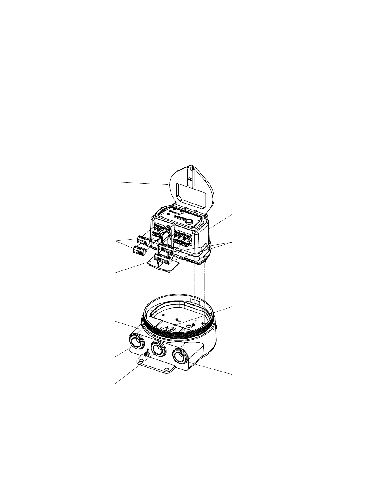
Figure 1-1. RFT9739 exploded view
Removable cover
of housing
Hinged cover of
electronics module
Diagnostic LED
Electronics modu le
Intrinsically safe
terminals for wiring
to sensor
Partition (safety barrier)
Must be in place during
operation of transmitter
Housing base
Switches 1 through 10
Zero button
Non-intrinsically safe
output termina l s
Power-supply wiring
and equipment ground
terminals
2
RFT9739 Field-Mou nt Tra nsm i t t er Instruction Manual
Page 13

2 Getting Started
Hazardous area
approvals tag
2.1 Hazardous area installations
WARNING
Failure to comply with requirements for intrinsic
safety in a hazardous area could result in an
explosion.
• Install the transmitter in an environment that is
compatible with the hazardous area specified on the
approvals tag. See
• For intrinsically safe inst allati ons , use this docu me nt with
Micro Motion UL, CSA, or SAA installation instructions.
• For hazardous area installations in Europe, refer to
standard EN 60079-14 if nation al standards do not apply.
• Read the approvals tag before installing the RFT9739. The approvals
tag is attached to the transmitter housing. See
• For a complete list of UL, CSA, SAA, and European approvals, see
page 82.
• For intrinsically safe installations, use this manual with the appropriate
Micro Motion intrinsically safe installation instructions:
-
UL-D-IS Installation Instructions
-
CSA-D-IS Installation Instructions
-
SAA-D-IS Installation Instructions
• In Europe, refer to standard EN60079-14 if national standards do not
apply. To comply with CENELEC standards, see page 4.
Figure 2-1
.
Figure 2-1
.
Pow er-Supply and
Sensor Wiring
Output Wiring Startup TroubleshootingBefore You Begin Getting Started Mounting
Figure 2-1.
Hazardous area approvals
tag
RFT9739 Field-Mount Tra nsm it te r Instruction Manual
3
Page 14

Getting Started
continued
Installations in Europe
2.2 Configuration, calibration, and characterization
To comply with CENELEC standards for hazardous area installations in
Europe, adhere to the following CENELEC conditions for safe use.
Cable glands and conduit seals
• Use 3/4"-14 NPT cable glands or conduit fittings, rated flameproof for
EEx d IIC areas and certified by an authorized test station. Flameproof
glands supplied by Micro Motion meet these requirements.
• Conduit openings that are not used should be sealed with blanking
plugs of type PLG 2.
• For installation in a nonhazardous area, cable glands or conduit fittings
that do not carry a flameproof rating are acceptable.
Potential equalization
To achiev e potential equalization, the RFT9739 ground conductor should
be connected to the appropriate ground terminals within the hazardous
area, using a potential equalizing line.
Output wiring
Nonintrinsically-safe connections between the RFT9739 and other
devices may be made
or equal to 250 V.
The following information explains the differences among configuration,
calibration, and characterization. Certain parameters might require
configuration
even when
only
to devices that maintain a voltage less than
calibration
is not necessary.
Configuration parameters
measurement units, flow direction, damping values, slug flow
parameters, and span values for the milliamp and frequency outputs. If
requested at time of order, the transmitter is configured at the factory
according to customer specifications.
Calibration
density, and temperature. Field calibration is optional.
Characterization
density, and temperature directly into transmitter memory. Calibration
factors can be found on the sensor serial number tag and on the
certificate that is shipped with the sensor.
For configuration, calibration, or characterization procedures, see one of
the following communications manuals:
Using the HART Communicator with Micro Motion Transmitters
•
Using ProLink Software with Micro Motion Transmitters
•
Using Modbus Protocol with Micro Motion Transmitters
•
You can also use Fisher-Rosemount™ Asset Management Solutions
(AMS) software for configuration, calibration, and characterization. For
more information, see the AMS on-line help.
A basic software tree for the HART Communicator is shown in
Appendix D
accounts for an individual sensor’s sensitivity to flow,
is the process of entering calibration factors for flow,
, page 91.
include items such as flowmeter tag,
4
RFT9739 Field-Mou nt Tra nsm i t t er Instruction Manual
Page 15

Getting Started
continued
2.3 Switch settings
Security modes
Switches 1 through 10 on the electronics module control the following
transmitter functions:
• Baud rate
• Stop bits and parity
• Data bits, communication protocol, and physical layer
• mA outputs
• Zeroing method
• Write-protection of transmitter configuration
Switches 1 through 10 are illustrated in
Figure 2-2
, and described in the
following sections. Normally, switch settings do not require adjustment.
Switches 1, 2, and 3 are security switches, which enable the user to
disable flowmeter zeroing, disable resetting of totalizers, and writeprotect all configuration and calibration parameters.
Switch settings enable any of eight possible security modes. Different
modes determine which functions are disabled and whether
configuration and calibration parameters are write-protected. The
following functions can be disabled:
• Flowmeter zeroing using digital communications
• Flowmeter zeroing using the zero button and, if the transmitter has a
display, the Scroll and Reset knobs
• Totalizer reset, with flow, using digital communications
• Totalizer reset, with flow, using the Scroll and Reset knobs, if the
transmitter has a display
• Totalizer control, with zero flow, using digital communications
• Totalizer control, with zero flow, using the Scroll and Reset knobs, if the
transmitter has a display
• Ability to change configuration or calibration factors
Pow er-Supply and
Sensor Wiring
Table 2-1
are disabled for each security mode. Security modes 1 through 7 are
entered immediately when switches 1 through 3 are set.
For information about security mode 8, see pages 6 through 8.
Figure 2-2. Switches
RFT9739 Field-Mount Tra nsm it te r Instruction Manual
lists the parameters that are write-protected and functions that
Switches 1 through 10 at left
are shown in the OFF position.
Output Wiring Startup TroubleshootingBefore You Begin Getting Started Mounting
5
Page 16

continued
Getting Started
Table 2-1. Security modes
Switch settings
Switch 1
Switch 2
Switch 3
Function/
parameter
Flowmeter
zeroing
Totalize r
control,
no flow
Totalize r
control,
with flow
Configuration and
calibration parameters
* C hanging the settings of switches 1, 2, and 3 does not immediately impl em ent security mode 8. For more information about
security mode 8, see pages 6 through 8.
Performed
with
Zero but t on or
Reset knob
HART or
Modbus
Scroll and
Reset knobs
HART or
Modbus
Scroll and
Reset knobs
HART or
Modbus
Mode
1
OFF
OFF
OFF
Mode
1
Mode
2
OFF
OFF
ON
Mode
2
Disabled Disabled Disabled Disabled Disabled Disabled Disabled
Disabled Disabled Disabled Disabled
Disabled Disabled Disabled Disabled Disabled Disabled Disabled
Mode
3
OFF
ON
OFF
Mode
3
Disabled Disabled Disabled Disabled
Disabled Disabled Disabled
Disabled Disabled Disabled Disabled Disabled Disabled
Write-
protected
Mode
4
OFF
ON
ON
Mode
4
Write-
protected
Mode
5
ON
OFF
OFF
Mode
5
Write-
protected
Mode
6
ON
OFF
ON
Mode
6
Write-
protected
Mode
7
ON
ON
OFF
Mode
7
Write-
protected
Mode
8*
ON
ON
ON
Mode
8
Write-
protected
Security mode 8
When transmitter security is set for mode 8, the transmitter meets
security requirements for custody transfer described in National Institute
of Standards and Technology (NIST) Handbook 44.
Once the transmitter is configured for security mode 8, the security
mode cannot be changed unless a master reset is performed. A master
reset causes all configuration parameters to return to their default
values, and
requires complete characterization and reconfiguration
of the trans m i tt e r.
If the user attempts to enter a new security mode or change the
transmitter configuration after entering security mode 8:
• Internal totalizers stop counting
• The frequency/pulse output goes to 0 Hz
• mA outputs go to 4 mA
• The optional display reads, "SECURITY BREACH; SENSOR OK"
• Custody transfer event registers record changes made to defined
configuration and calibration parameters. (For a list of these
parameters, see
Table 6-2
, page 56.)
The security breach continues, and totalizers and outputs remain
inactive, until the transmitter is reconfigured for security mode 8, or until
a master reset has been performed. Custody transfer ev ent registers are
not affected by a master reset.
• For information about event registers, see
• To perform a master reset, see instructions in
Section 6.3
Section 7.7
, page 56.
, page 74.
6
RFT9739 Field-Mou nt Tra nsm i t t er Instruction Manual
Page 17

Getting Started
continued
Milliamp output trim, milliamp output test, and frequency/pulse output
test procedures cannot be performed after security mode 8 is entered.
Before entering security mode 8,
perform milliamp trim and/or test
procedures, if necessary , as described in any of the following manuals or
in AMS on-line help:
Using the HART Communicator with Micro Motion Transmitters
•
Using ProLink Software with Micro Motion Transmitters
•
Using Modbus Protocol with Micro Motion Transmitters
•
To enter security mode 8:
1. Note the position of switch 5.
2. Set switch 10 to the ON position. The diagnostic LED on the
transmitter electronics module flashes on 3 times and pauses, which
indicates the transmitter is in the configuration mode.
3. Set switches 1, 2, and 3 to the ON position.
4. Set switches 4, 5, and 6 to the OFF position.
5. Locate the ZERO button on the transmitter electronics module.
6. Press and hold the ZERO button for five seconds. The diagnostic LED
will remain on for two to three seconds to indicate security mode 8
has been entered.
7. Reset switch 5 to the desired position (as noted in Step 1).
8. Reset switch 10 to the OFF (OPERATE) position. The diagnostic LED
flashes on once per second (25% on, 75% off), which indicates the
transmitter is in the normal operating mode.
9. Leave switches 1, 2, and 3 in the ON position to remain in security
mode 8.
Pow er-Supply and
Sensor Wiring
To verify the transmitter is in security mode 8:
• If the transmitter has a display, use the Scroll knob to scroll through
process variable screens to event register screens. If event register
screens appear, the transmitter is in security mode 8. For more
information about using the Scroll knob and transmitter display, see
Section 6.2
, page 51.
• If the transmitter does not have a display:
1. Configure the transmitter.
2. Wait until the diagnostic LED blinks ON once per second.
3. Move switch 1, 2, or 3 to the OFF position.
4. If the diagnostic LED blinks ON 4 times per second, the transmitter
is in security mode 8.
Output Wiring Startup TroubleshootingBefore You Begin Getting Started Mounting
RFT9739 Field-Mount Tra nsm it te r Instruction Manual
7
Page 18

Getting Started
continued
To make changes to configuration or calibration parameters once
security mode 8 is entered:
1. Set switches 1, 2, and 3 to the OFF position.
2. Make changes through digital communication or, if the transmitter has
a display, with the Scroll and Reset knobs (see "Communication
configuration mode," page 54). Custody transfer event registers
record changes made to defined configuration and calibration
parameters (see
Table 6-2
, page 56). For more information about
digital com m uni cati ons , see th e following ins truc tion m an ual s or AM S
on-line help:
Using the HART Communicator with Micro Motion Transmitters
•
Using ProLink Software with Micro Motion Transmitters
•
Using Modbus Protocol with Micro Motion Transmitters
•
3. Set switches 1, 2, and 3 to the ON position.
To reenter security mode 8:
If security mode 8 has been established previously, and the security
mode has been temporarily changed, it is not necessary to use the
ZERO button to reenter security mode 8. In such a case, resetting
switches 1, 2, and 3 to the ON position will reenter security mode 8
immediately.
If a master reset has been performed, it is necessary to use the ZERO
button method to reenter security mode 8. See procedure, page 7.
To change from security mode 8 to another security mode:
1. Perform a master reset (see
Section 7.7
, page 74, for master reset
procedure).
2. Perform characterization and reconfiguration procedures as
described in any of the following instruction manuals:
Using the HART Communicator with Micro Motion Transmitters
•
Using ProLink Software with Micro Motion Transmitters
•
Using Modbus Protocol with Micro Motion Transmitters
•
3. Set switches 1, 2, and 3 to the desired positions (see
Table 2-1
,
page 6).
8
RFT9739 Field-Mou nt Tra nsm i t t er Instruction Manual
Page 19

Getting Started
continued
Communication settings
Switch 5 enables the user to choose the standard communication
configuration or user-defined parameters. With switch 10 in the ON
(CONFIG) position, switches 1 through 6 can be used for setting userdefined communication parameters.
Standard communication setting
To use the standard communication configuration, set switch 5 to the
STD COMM position. Setting the switch in this position establishes the
following communication parameters:
• HART protocol on the Bell 202 standard, at 1200 baud, on the primary
mA output
• Modbus protocol in RTU mode, at 9600 baud, on the RS-485 output
• 1 stop bit, odd parity
For RFT9739 software versions 3.6 and later, if switch 5 is in the STD
COMM position, and the RFT9739 has a display, an error message will
appear on the display when an attempt is made to change the
communication configuration using the RFT9739 display controls.
User-defined communication settings
To establish user-defined settings, set switches as instructed in
Table 2-2
, page 10. With switches 1 through 6, the user can set baud
rate; stop bits and parity; data bits, protocol, and physical layer. The
default settings are HART protocol, over RS-485, at 1200 baud, with
1 stop bit and odd parity.
Pow er-Supply and
Sensor Wiring
Milliamp output scaling
Switches 7, 8, and 9 allow the user to choose 0-20 mA or 4-20 mA
scaling for mA outputs, and upscale or downscale fault outputs.
Switch 7 defines the primary mA output scaling. Switch 8 defines the
secondary mA output scaling. Either switch may be set in the 0-20
position or the 4-20 position.
• The mA outputs are NAMUR compliant when switches 7 and 8 are in
the 4-20 position. See
Section 5.3
, page 27.
• Communication using the HART protocol over the primary mA output
requires switch 7 to be set in the 4-20 position.
• If switch 7 is in the 0-20 mA position, communication may be lost if
output is less than 2 mA. T o re-establish communication, move s witch 7
to the 4-20mA position.
Switch 9 defines the RFT9739 fault outputs. Fault outputs can be set for
downscale or upscale levels.
• If switch 9 is set to the DWNSCALE position, mA outputs go to 0 mA if
they produce a 0-20 mA current, or to 0-2 mA if they produce a
4-20 mA current; the frequency/pulse output goes to 0 Hz.
• If switch 9 is set to the UPSCALE position, mA outputs go to 22-24 mA;
the frequency/pulse output goes to 15-19 kHz.
• For more information, see "Fault outputs," page 65.
Output Wiring Startup TroubleshootingBefore You Begin Getting Started Mounting
RFT9739 Field-Mount Tra nsm it te r Instruction Manual
9
Page 20

continued
Getting Started
Table 2-2. Communications configuration
Instructions
Before beginning, make note of the positions of switches 1, 2, and 3. Then, for each setting:
1. Begin with switch 10 in the CONFIG position, and switches 1 through 6 in the OFF position. The LED flashes ON 3 times and
pauses, which indicates th e transm i t te r is i n th e communication configuration mo de.
2. Set designated switches to the ON position as indicated below.
3. Press and hold the ZERO button for five seconds, until the LED remains ON for 3 seconds, which indicates the setting ha s
been accepted by the transmitter.
When done:
1. Reset switches 1, 2, and 3 to the appropriate positions.
2. Set switch 5 to the USER DEFINED position.
3. Set switches 4 and 6 to the OFF position.
4. Set switch 10 to the OPERATE position.
Note
If switches 4, 5, 6, and 10 are left in the ON position after configuration, a master reset will occur the next time power to the
transmitter is shut off and the n re st or ed. To avoid an unexpected mast er reset, make sure switches 4, 6, and 10 are left in the
OFF position after con fig urati on.
Baud rate
1200 baud ON ON
2400 baud ON ON ON
4800 baud ON ON
9600 baud ON ON ON
19,200 baud ON ON ON
38,400 baud ON ON
Stop bits and parity
1 stop bit, no parity ON
1 stop bit, odd parity ON ON
1 stop bit, even parity ON ON ON
2 stop bits, no parity ON ON
2 stop bits, odd parity ON ON ON
2 stop bits, even parity ON ON
Data bits, protocol, physical layer
HART on primary mA ON ON ON ON
HART on RS-485 ON ON ON
Modbus RTU mode (8 bits) on RS-485 ON ON
Modbus ASCII mode (7 bits) on RS-485 ON ON ON
Modbus RTU mode (8 bits) on RS-485
and HART on primary mA
Modbus ASCII mode (7 bits) on RS-485
and HART on primary mA
Switch
1
Switch
1
Switch
1
ON ON ON
ON ON ON ON
Switch
2
Switch
2
Switch
2
Switch
3
Switch
3
Switch
3
Switch
4
Switch
4
Switch
4
Switch
5
Switch
5
Switch
5
Switch
6
Switch
6
Switch
6
10
RFT9739 Field-Mou nt Tra nsm i t t er Instr uc t io n M anual
Page 21
3 Transmitter Mounting
3.1 General guidelines
Follow these guidelines when installing the field-mount RFT9739
transmitter:
• Locate the transmitter where it is accessible for service and calibration.
• In hazardous areas, install the transmitter in a location that is specified
Section 2.1
in
• Total length of cable from the sensor to the transmitter must not exceed
1000 feet (300 meters).
• Locate the transmitter where the ambient temperature remains
between –22 and 131°F (–30 and 55°C). If the transmitter has a
display, the display might become difficult to read below 14°F (–10°C).
• Mount the transmitter to a stable, flat surface or instrument pole.
• The cover of the transmitter housing requires 11½ inches (292 mm)
clearance for removal. If the transmitter has a display, the cover
requires 13 3/16 inches (335 mm) clearance.
The base of the transmitter has three ¾-inch NPT female conduit
openings (see
keep the transmitter watertight.
, page 3.
Figure 3-1
, next page), which must remain sealed to
CAUTION
Failure to seal transmitter housing could cause a
short circuit, which w ould result i n measuremen t err or
or flowmeter failure.
Pow er-Supply and
Sensor Wiring
To avoid risk of condensation or excessive moisture
entering the transmitter housing, fully seal all conduit
openings when installing the transmitter.
• Install conduit that allows a complete seal with the conduit openings.
• If possible, orient the transmitter with its conduit openings pointed
downward. If this is not possible, seal the conduit to prevent
condensation and other moisture from entering the housing.
• To comply with CENELEC standards for hazardous area installations in
Europe:
-
Use cable glands or conduit fittings rated flameproof for EEx d IIC
areas and certified by an authorized test station. Flameproof glands
supplied by Micro Motion meet these requirements.
-
Conduit openings that are not used should be sealed with blanking
plugs of type PLG 2.
-
For installation in a nonhazardous area, cable glands or conduit
fittings that do not carry a flameproof rating are acceptable.
• If the transmitter has a display, the display will be right-side-up only if
the transmitter is oriented with its conduit openings pointed downward.
RFT9739 Field-Mount Tra nsm it te r Instruction Manual
Output Wiring Startup TroubleshootingBefore You Begin Getting Started Mounting
11
Page 22
Transmitter Mounting
continued
3.2 Mounting to a wall
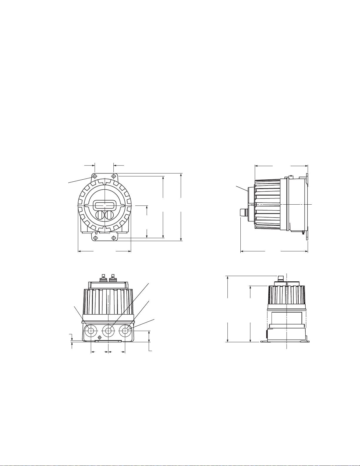
Figure 3-1. RFT9739 dimensions
4X Ø
inches
(mm)
2 13/16
(71)
23/64
(9)
Dimensions in
Follow these guidelines and refer to
Figure 3-1
to mount the transmitter
to a wall or other flat, rigid surface.
• Use four 5/16-inch diameter (or M8) bolts and nuts to mount the
transmitter to a wall or other flat, rigid surface. Use bolts and nuts that
can withstand the process environment. Micro Motion does not supply
bolts or nuts (such bolts and nuts are available as an option).
• To minimize stress on the housing, secure all four mounting bolts to the
same structure, which should be flat and should not vibrate or move
excessively. Do not secure bolts to separate girders, beams, or wall
studs, which can move independently.
7 19/64
(185)
Optional
display
8 3/8
9 11/64
(213)
4 33/64
(115)
(233)
Sensor cable
conduit opening
3/16
(5)
7 15/64
(184)
2 3/8
(60)
2 3/8
(60)
Power-supply wiring
conduit opening
Output wiring
conduit opening
3x
3/4"-14 NPT
conduit opening
1 17/32
(39)
9 1/8
(232)
Removal of cover required for
access to wiring compartments
With
display
13 3/16
(335)
Without
display
11 1/2
(292)
12
RFT9739 Field-Mou nt Tra nsm i t t er Instr uc t io n M anual
Page 23
Transmitter Mounting
continued
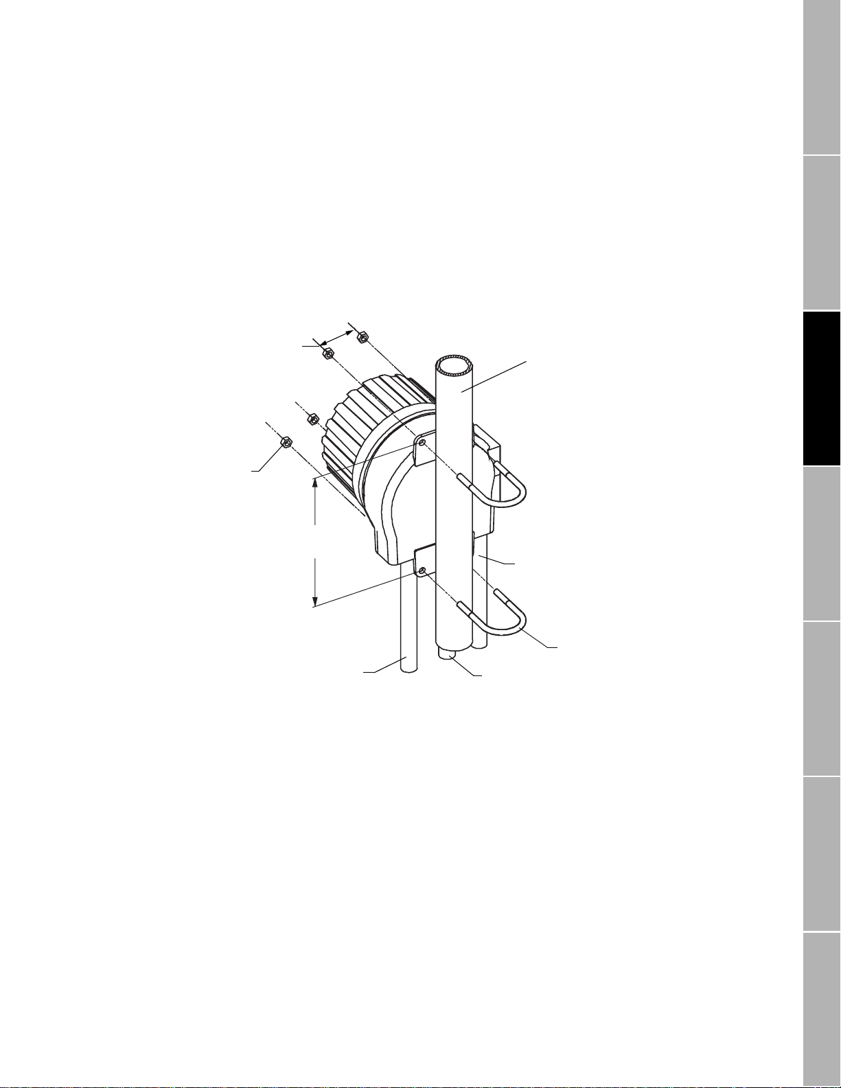
3.3 Mounting to an instrument pole
Figure 3-2. Instrument-pole mounting
Dimensions in
inches
(mm)
4X
5/16
(8)
2X
2 13/16
(71)
Follow these guidelines and refer to
Figure 3-2
to mount the transmitter
to an instrument pole:
• Use two 5/16-inch U-bolts for 2-inch pipe, and four matching nuts, to
mount the transmitter to a rigid instrument pole. Use U-bolts and nuts
that can withstand the process environment. Micro Motion does not
supply U-bolts or nuts.
• The instrument pole should extend at least 12 inches (305 mm) from a
rigid base, and be no more than 2 inches (50.8 mm) in diameter.
2-inch pipe
Pow er-Supply and
Sensor Wiring
2X
8 3/8
(213)
Output wiring
conduit
Sensor cable
wiring conduit
Power-supply
wiring conduit
5/16"-18 U-bolt
2X
for 2-inch pipe
Output Wiring Startup TroubleshootingBefore You Begin Getting Started Mounting
RFT9739 Field-Mount Tra nsm it te r Instruction Manual
13
Page 24

14
RFT9739 Field-Mou nt Tra nsm i t t er Instr uc t io n M anual
Page 25
4 Power-Supply and Sensor
Wiring
4.1 General guidelines
WARNING
Failure to comply with requirements for intrinsic
safety in a hazardous area could result in an
explosion.
Sensor wiring is intrinsically safe.
• Keep intrinsically safe sensor wiring separated from
power-supply wiring and output wiring.
• For intrinsically safe sensor inst allations, use this
document with Micro Motion UL, CSA, or SAA installat ion
instructions.
• For hazardous area installations in Europe, refer to
standard EN 60079-14 if nation al standards do not apply.
• Make sure the safety barrier partition is in place before
operating the transmitter.
CAUTION
Failure to seal transmitter housing and sensor
junction box could cause a short circuit, which would
result in measurement error or flowmeter failure.
To avoid risk of condensation or excessive moisture in the
junction box or transmitter housing:
• Seal all conduit openings.
• Install drip legs in cable or conduit.
• Ensure integrity of gaskets and O-rings, and fully tighten
all covers.
Pow er-Supply and
Sensor Wiring
Output Wiring Startup TroubleshootingBefore You Begin Getting Started Mounting
A removable partition on the electronics module keeps intrinsically safe
wiring to the sensor separated from nonintrinsically safe output wiring.
The module has a hinged, clear plastic cover. To access power-supply
wiring terminals, unlatch the cover of the module, then remove the
partition.
Figure 4-1
•
the sensor, output wiring terminals, and power-supply wiring terminals.
• Terminal blocks may be unplugged from the module for easier
installation of wiring.
• Install cable and wiring to meet local code requirements.
• A switch may be installed in the power-supply line. For compliance with
low-voltage directive 73/23/EEC, a switch in close proximity to the
transmitter is required for AC-powered transmitters.
• Do not install AC power cable or unfiltered DC power cable in the same
conduit or cable tray as sensor cable or output wiring.
RFT9739 Field-Mount Tra nsm it te r Instruction Manual
, page 16, shows the locations of the terminals for wiring to
15
Page 26
continued
Power-Supply and Sensor Wiring
Figure 4-1. RFT9739 exploded view
Hinged cover of
electronics module
The base of the transmitter has three ¾-inch NPT female conduit
openings, indicated in
Figure 4-1
, which must rem ain seal ed to k eep the
transmitter watertight.
• Use conduit that allows a complete seal with the conduit openings.
• If possible, orient the transmitter with its conduit openings pointed
downward. Seal the conduit to prevent condensation and other
moisture from entering the housing.
• To comply with requirements for explosion-proof installations approved
by UL or CSA, install approved explosion-proof conduit seals on all
three conduit openings.
• To comply with CENELEC requirements for installations in Europe, see
page 17.
Intrinsically safe
terminals for wiring
to sensor
Partition (safety barrier)
Must be in place during
operation of transmitter
Housing base
Sensor wiring
conduit opening
Power-supply
conduit opening
Electronics module
Non-intrinsically safe
output terminals
Power-supply wiring
and equipment ground
terminals
Output wiring
conduit opening
16
RFT9739 Field-Mou nt Tra nsm i t t er Instr uc t io n M anual
Page 27
Power-Supply and Sensor Wiring
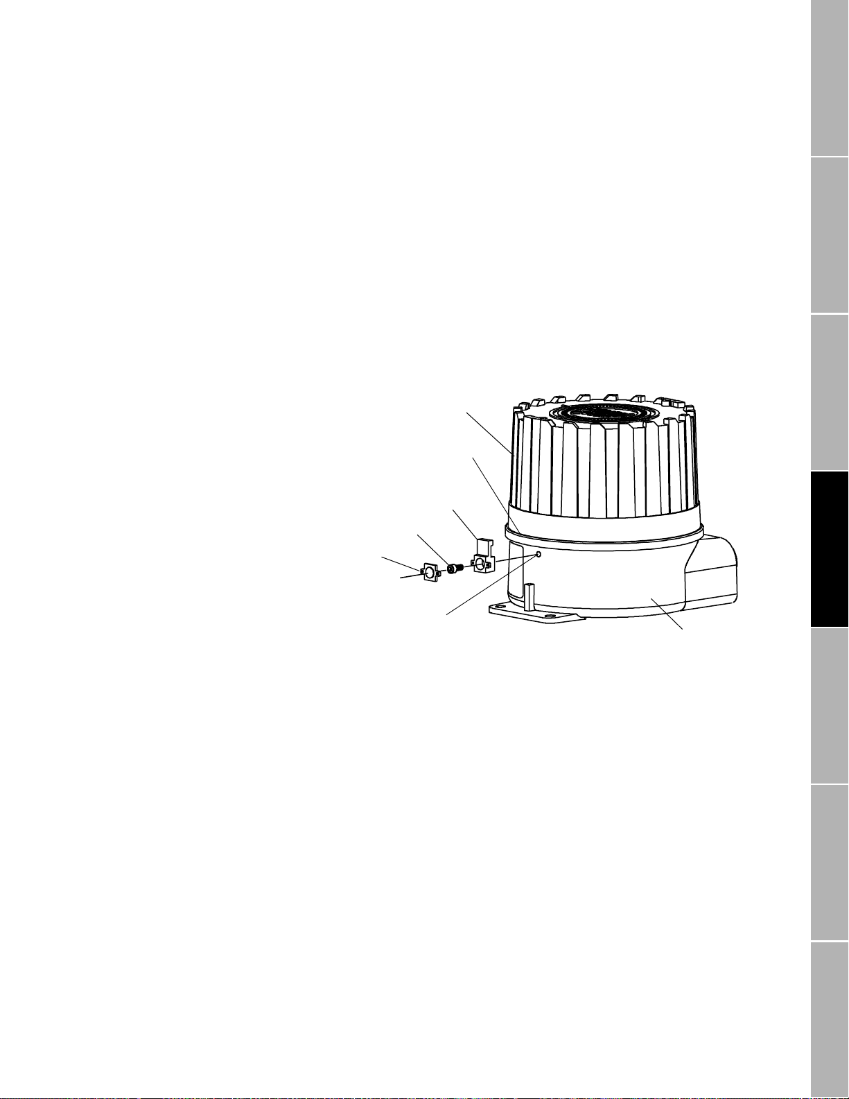
Housing cover
Lip
Clamp
Mounting screw
Cap
Threaded hole
Housing base
continued
Installations in Europe
Figure 4-2.
Lockout clamp for
CENELEC transmitters
To comply with CENELEC standards for hazardous area installations in
Europe, adhere to the following CENELEC conditions for safe use:
• Use 3/4"-14 NPT cable glands or conduit fittings, rated flameproof for
EEx d IIC areas and certified by an authorized test station. Flameproof
glands supplied by Micro Motion meet these requirements.
• Conduit openings that are not used should be sealed with blanking
plugs of type PLG 2.
• For installation in a nonhazardous area, cable glands or conduit fittings
that do not carry a flameproof rating are acceptable.
A CENELEC-compliant RFT9739 includes a lockout clamp on the
transmitter housing. See
Figure 4-2
. The clamp adds secondary
protection against accessing the power-supply terminals, and is required
to meet CENELEC standards.
Pow er-Supply and
Sensor Wiring
RFT9739 Field-Mount Tra nsm it te r Instruction Manual
Output Wiring Startup TroubleshootingBefore You Begin Getting Started Mounting
17
Page 28

Power-Supply and Sensor Wiring
continued
4.2 Power supply and grounding
Power-supply options
Wiring
CAUTION
Incorrect vol tage, or install ation with po wer s upply on,
will cause transmitter damage or failure.
• Turn off power before installing transmitter.
• Match power-supply voltage with voltage indicated in
transmitter power terminals compartment.
The AC transmitter accepts an 85 to 250 VAC power supply. The DC
transmitter accepts a 12 to 30 VDC power supply.
• A label inside the power-supply wiring compartment indicates the
correct power-supply voltage.
Figure 4-3
•
terminals in the base of the transmitter housing.
• A lockout clamp on the transmitter housing (see
provides secondary protection against accessing the power-supply
terminals, and is required by CENELEC.
To install power-supply wiring, follow these steps:
1. To access power-supply wiring, unlatch the hinged cover of the
module, then remove the partition that separates intrinsically safe
sensor wiring from non-intrinsically safe output wiring.
2. Make input power connections at the two labeled terminals, as
indicated in
labeled as follows:
• If the terminals are labeled "L" (line) and "N" (neutral), install an
85 to 250 VAC power supply.
• If the terminals are labeled "+" (positive) and "–" (negative), install a
12 to 30 VDC power supply.
3. Ground the transmitter as instructed on page 19.
(next page) shows the location of power-supply wiring
Figure 4-3
Figure 4-2
(next page). The power supply terminals are
, page 17)
18
RFT9739 Field-Mou nt Tra nsm i t t er Instr uc t io n M anual
Page 29

Power-Supply and Sensor Wiring
Equipment
ground
Power-supply conduit opening
Equipment
ground
Transmitter
power rating
Terminal
labels
85-250 VAC 50/60 H z L N
12-30 VDC +
−
Figure 4-3.
Power-supply wiring
terminals
continued
Grounding
WARNING
Failure to comply with requirements for intrinsic
safety in a hazardous area could result in an
explosion.
• T he transmitter must be properly grounded.
• Follow the instructions below to ground the transmitter.
• For hazardous area installations in Europe, refer to
standard EN 60079-14 if nation al standards do not apply.
To ensure proper grounding:
• If the installation must comply with UL, CSA, or SAA standards, refer to
the instructions in one of the following Micro Motion documents:
-
UL-D-IS Installation Instructions
-
CSA-D-IS Installation Instructions
-
SAA-D-IS Installation Instructions
• In most installations, install grounding as illustrated in
(next page).
• For installations in Europe, and to comply with CENELEC standards,
install grounding as illustrated in
Figure 4-4b
(next page).
• To achieve potential equalization and comply with CENELEC
standards for hazardous area installations in Europe, the RFT9739
external ground terminal (see
Figure 4-4b
) should be connected to the
appropriate ground terminals within the hazardous area, using a
potential equalizing line.
Figure 4-4a
Pow er-Supply and
Sensor Wiring
Output Wiring Startup TroubleshootingBefore You Begin Getting Started Mounting
RFT9739 Field-Mount Tra nsm it te r Instruction Manual
19
Page 30
continued
Power-Supply and Sensor Wiring
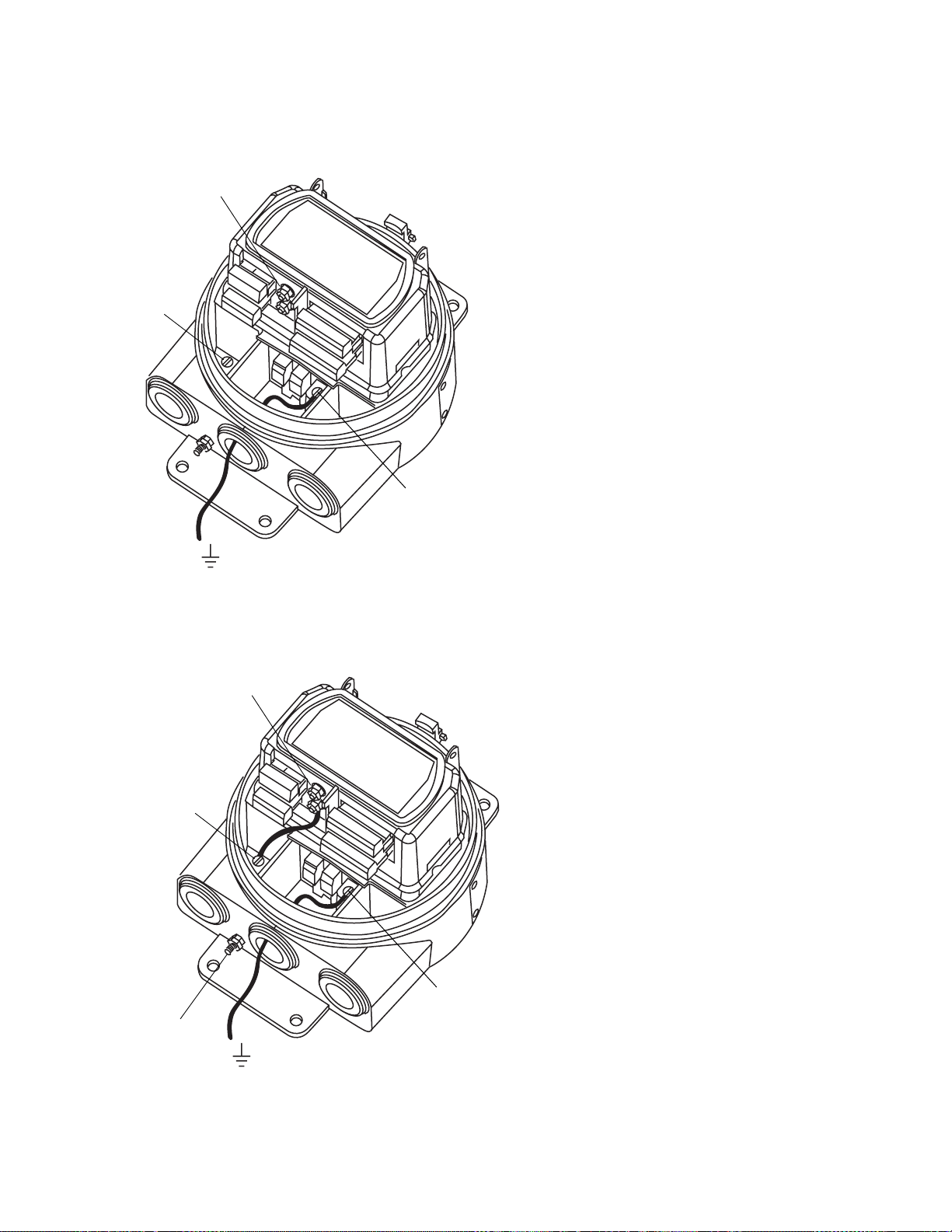
Figure 4-4a. Grounding detail — typical
I.S. ground
terminals
Internal
case ground
terminal
Power ground
terminal
Earth ground
Figure 4-4b. Grounding detail — European installations
I.S. ground
terminals
If national standards are not in e ffect, adhere to
these guidelines for grounding:
• Use copper wire, 14 AWG (2.5 mm²) or larger
wire size.
• Keep all ground leads as short as pos si ble, less
than 1 ohm impe dance.
• Connect I.S. ground terminals di r ect l y to in te rnal
case ground termi nal.
• Connect ground lead from power ground terminal
directly to earth ground.
• Follow plant standards, instead of this standard, if
a separate high-integrit y in trinsically safe ground
scheme is used.
Internal
case ground
terminal
External ground
terminal
20
Earth ground
Power ground
terminal
If national standards ar e not in effect, adhere to
these guidelines for grounding:
• Use copper wire, 14 AWG (2.5 mm²) or larger
wire size.
• Keep all ground leads as short as possible, less
than 1 ohm impedance.
• A factory-installed ground wire, connecting the
I.S. ground and internal case-ground terminals,
must remain i n p l ace.
• Connect ground lead from power ground terminal
directly to earth ground.
• Follow plant standards, instead of this standard, if
a separate high-integr ity intrinsically safe ground
scheme is used.
• To achieve potential equalization and comply with
CENELEC standar ds for hazardous area
installations in Europe, connect the external
ground terminal to the appropriate ground
terminals withi n t he hazardous area, using a
potential equalizing line.
• For hazardous area installation in Europe, use
standard EN 60079-1 4 as a guideline.
RFT9739 Field-Mou nt Tra nsm i t t er Instr uc t io n M anual
Page 31

Power-Supply and Sensor Wiring
continued
4.3 Sensor wiring
Cable connections to
sensor and transmitter
The instructions in this section explain how to connect a fully prepared
Micro Motion flowmeter cable to the RFT9739 and a sensor. The sensor
can be a Micro Motion ELITE, F-Series, Model D, DT, or DL sensor.
• The procedure for preparing Micro Motion flowmeter cable and cable
glands is described in the instructions that are shipped with the cable.
• Install cable and wiring to meet local code requirements.
• Use Micro Motion color-coded cable.
• Total length of cable from the sensor to the transmitter must not exceed
1000 feet (300 meters).
WARNING
Operating the transmitter without covers in place
exposes electrical hazards that can cause property
damage, injury, or death.
Make sure the safety barrier partition, electronics module
cover, and housing cover are securely in place before
operating the transmitter.
CAUTION
Failure to seal sensor junction box and transmitter
housing could cause a short circuit, which would
result in measurement error or flowmeter failure.
Pow er-Supply and
Sensor Wiring
To avoid risk of condensation or excessive moisture in the
junction box or transmitter housing:
• Seal all conduit openings.
• Install drip legs in conduit or cable.
• Ensure integrity of gaskets and O-rings, and fully tighten
all housing covers.
CAUTION
Improper installation of cable or conduit could cause
inaccurate measurements or flowmeter failure.
Keep cable away from devices such as transformers,
motors, and power lines, which produce large magnetic
fields.
Output Wiring Startup TroubleshootingBefore You Begin Getting Started Mounting
RFT9739 Field-Mount Tra nsm it te r Instruction Manual
21
Page 32

Power-Supply and Sensor Wiring
continued
The wiring procedure is the same for the sensor and transmitter. Refer to
the hazard statements on page 21 and the wiring diagrams below and
on page 23, and follow these steps:
1. Insert the stripped ends of the individual wires into the terminal
blocks. No bare wires should remain exposed.
• At the sensor, connect wiring inside the sensor junction box.
• At the transmitter, connect wiring to the transmitter's intrinsically
safe terminals for sensor wiring, as numbered in
Table 4-1
Transmitter terminal blocks can be unplugged for easier connection
of wiring.
.
Table 4-1.
Terminal designations
Figure 4-5. Wiring to ELITE
®
CMF sensors
2. Locate the wires by color as indicated in
Table 4-1
.
3. Tighten the screws to hold the wires in place.
4. Tightly close the sensor junction-box cover and transmitter housing.
On an ELITE sensor junction box, tighten all four cover screws.
Wire
color
Black*
Brown11Drive +
Red22Drive –
Orange 3 3 T em perature –
Yell ow 4 4 Temperature return
Green 5 5 Left pickoff +
Blue 6 6 Ri gh t pickoff +
Violet 7 7 Temperature +
Gray 8 8 Right pickoff –
White 9 9 Left pickoff –
* C ombined drain wires from brown/re d, green /wh ite, and gray/blue pairs, and
yellow/orange/violet triplet.
Sensor
terminal
Transmitter
terminal Function
No connection 0 Drain wires*
22
ELITE® sensor
terminals
Green
White
Brown
Violet
Yellow
Orange
Blue
Gray
Red
Brown
Clip drain wire back
Clip drain wire back
Clip drain wire back
Clip drain wire back
Red
Green
White
Blue
Gray
Orange
Violet
Yellow
Flowmeter
cable
Maximum cable length 1000 ft. (300 m)
Prepare cable in accordance with the
instructions that are shipped with the cable
RFT9739 Field-Mou nt Tra nsm i t t er Instr uc t io n M anual
Black
(Drains from all
wire sets)
Brown
Red
Green
White
Blue
Gray
Orange
Violet
Yellow
Field-mount
RFT9739 terminals
Brown
Orange
Green
Violet
White
Gray
Blue
Yellow
Red
Black (Drains)
Page 33

continued
Power-Supply and Sensor Wiring
Figure 4-6. Wiring to F-Series, Model D, and DL sensors
F-Series, Model D
or DL sensor
terminals
Brown
Red
Orange
Yellow
Green
Blue
Violet
Gray
White
Clip drain wire back
Clip drain wire back
Clip drain wire back
Clip drain wire back
Maximum cable length 1000 ft. (300 m)
Brown
Red
Green
White
Blue
Gray
Orange
Violet
Yellow
Prepare cable in accordance with the
instructions that are shipped with the cable
Figure 4-7. Wiring to Model DT sensors
Model DT
sensor terminals
User-supplied*
metal junction box with
terminal block
1
2
3
4
5
6
7
8
Sensor wire number
9
Brown
Red
Orange
Yellow
Green
Blue
Violet
Gray
White
Earth
ground
Clip drain wire back
Clip drain wire back
Clip drain wire back
Clip drain wire back
*In Europe, the DT-sensor junction box is supplied by the factory.
Brown
Red
Green
White
Blue
Gray
Orange
Violet
Yellow
Prepare cab l e in accor dan ce wi th t he in struc tio ns
Flowmeter
cable
Flowmeter
cable
Maximum cable length 1000 ft. (300 m)
that are shipped with the cable
Black
(Drains from all
wire sets)
Brown
Red
Green
White
Blue
Gray
Orange
Violet
Yellow
Black
(Drains from all
wire sets)
Brown
Red
Green
White
Blue
Gray
Orange
Violet
Yellow
Field-mount
RFT9739 terminals
Brown
Orange
Green
Violet
White
Gray
Blue
Yellow
Red
Black (Drains)
Field-mount
RFT9739 terminals
Brown
Orange
Green
Violet
White
Gray
Blue
Yellow
Red
Black (Drains)
Pow er-Supply and
Sensor Wiring
Output Wiring Startup TroubleshootingBefore You Begin Getting Started Mounting
RFT9739 Field-Mount Tra nsm it te r Instruction Manual
23
Page 34

24
RFT9739 Field-Mou nt Tra nsm i t t er Instr uc t io n M anual
Page 35

5 Output Wiring
5.1 General guidelines
WARNING
Failure to comply with requirements for intrinsic
safety in a hazardous area could result in an
explosion.
Output wiring is not intrinsically safe.
• Keep output wiring separated from power-supply wiring
and intrinsically safe sensor wiring.
• Follow all output wiring instructions to ensure transmitter
and any connected devices will operate correctly.
• Make sure the safety barrier partition is in place before
operating the transmitter.
A removable partition on the RFT9739 electronics module keeps
intrinsically safe wiring to the sensor separated from nonintrinsically saf e
output wiring. Use the upper and lower blocks on the right side of the
partition for output wiring connections.
page) describe terminal designations for the output terminals. Terminal
blocks can be unplugged from the module f or easier installation of wiring.
• The RFT9739 has separate conduit openings for power-supply wiring
and output wiring.
• To avoid possible electrical interference, do not install output wiring in
the same conduit or cable tray as sensor cable or power-supply wiring.
• Use individually shielded pairs of 22 AWG (0.3 mm²) or larger wires for
connections between the RFT9739 and any peripheral device.
• Shields and/or drain wires must be terminated outside the transmitter
housing, or left floating, as required by the installation.
• To comply with CENELEC standards for hazardous area installations in
Europe, nonintrinsically-safe connections between the RFT9739 and
other devices may
less than or equal to 250 V.
only
be made to devices that maintain a voltage
Figure 5-1
and
Table 5-1
(next
Pow er-Supply and
Sensor Wiring
Output Wiring Startup TroubleshootingBefore You Begin Getting Started Mounting
5.2 Maximum wire length
RFT9739 Field-Mount Tra nsm it te r Instruction Manual
Currently, there is no system for accurately estimating the maximum
length of wire between the RFT9739 and a connected peripheral device.
Most applications will be able to use wire lengths up to 500 feet for
22 AWG wire (150 meters for 0.3 mm² wire), 50 feet for 28 AWG wire
(15 meters for 0.1 mm² wire), between the transmitter and any
peripheral device. However, these distances are estimates only.
Prior to commissioning the transmitter, a loop-test is recommended as a
means for determining whether or not output signals are being received
correctly at the receiving device.
25
Page 36

continued
Output Wiring
Figure 5-1. Output terminals
Table 5-1.
Output wiring terminal
designations
Terminal Function
14 Frequency out put, DC supply voltage
15 and 16 Frequency/pulse output
17 and 18 Primary variable (PV) mA output
19 and 20 Secondary variable (SV) mA output
21 and 16 Remote zero input
22 and 16 Control output
23 Signal ground
24 and 23 Temperature output
25 and 23 Tube period output
26 and 27 RS-485 I/O
P DC power to pressure or DP transmitter
S mA input from pressure or DP transm i tter
HART Communicator hookup loo ps, sam e as PV mA output circuit
26
RFT9739 Field-Mou nt Tra nsm i t t er Instr uc t io n M anual
Page 37

Output Wiring
continued
5.3 Primary and secondary
mA outputs
The RFT9739 primary and secondary mA output signals can be
independently configured, and can represent flow, density, temperature,
event 1 or event 2. With a pressure transmitter, the primary and
secondary output signals can also represent pressure. For information
on configuring mA outputs for events, see any of the following manuals
or AMS on-line help:
Using the HART Communicator with Micro Motion Transmitters
•
Using ProLink Software with Micro Motion Transmitters
•
Using Modbus Protocol with Micro Motion Transmitters
•
The mA outputs can produce a user-selected 0-20 or 4-20 mA current.
(See "Milliamp output scaling," page 9).
• When configured to produce 4-20 mA current, the mA output loop can
supply loop-powered process indicators.
For transmitters with software version 3.8 or higher,
•
when
configured to produce 4-20 mA current, the mA outputs are compliant
with the NAMUR NE43 standard. (All RFT9739 transmitters shipped
after November 1999 have software version 3.8 or higher.)
CAUTION
Milliamp output range has changed.
When configured for 4-20 mA, milliamp outputs will not
output live signals between 2.0 and 3.8 mA, or between
20.5 and 22 mA.
Pow er-Supply and
Sensor Wiring
In compliance with the NAMUR NE43 standard:
• 4-20 mA outputs will produce a live signal from 3.8 to 20.5 mA.
• 4-20 mA outputs will not produce a signal between 2.0 and 3.8 mA, or
• 4-20 mA output performance is illustrated in
Figure 5-2. 4-20 mA output performance
Downscale
fault indication level
Systems that rely on milliamp output signals in the ranges
listed above might not perform as expected. For RFT9739
transmitters shipped after November 1999, outputs will
saturate at 3.8 and 20.5 mA, unlike previous versions of
these instruments.
Reconfigure systems as necessary.
between 20.5 and 22 mA.
Figure 5-2
Upscale
fault indication level
Operating range (live si gnal)
Output Wiring Startup TroubleshootingBefore You Begin Getting Started Mounting
.
2 3.8 2220.5
RFT9739 Field-Mount Tra nsm it te r Instruction Manual
Output, mA
27
Page 38

continued
Output Wiring
Use RFT9739 terminals 17 and 18 for the primary mA output. Use
terminals 19 and 20 for the secondary mA output. See
• Primary and secondary mA output loops are isolated and floating.
Additional grounding will result in optimum performance, and optimum
HART communication on the primary mA output. Ensure that mA
output loops are grounded properly, either at the transmitter end, or at
the external device.
• The maximum allowable length for mA signal wiring is determined by
measuring resistance over the signal wires and through the receiver
device. Total loop resistance must not exceed 1000 ohms.
• The primary mA output must be set to the 4-20 mA mode for the Bell
202 physical layer. The Bell 202 layer will not work with the primary mA
output configured as a 0-20 mA output.
• The mA output cannot be converted from active to passive.
Figure 5-3. Primary and secondary mA output wiring
PV+ (signal line)
PV– (return)
Figure 5-3
.
RFT9739
output terminals
SV+ (signal line)
SV– (return)
PV = Primary variable
SV = Secondary variable
28
RFT9739 Field-Mou nt Tra nsm i t t er Instr uc t io n M anual
Page 39

Output Wiring
continued
Connections for HART®
communication devices
Figure 5-4
ProLink PC-Interface adaptor, or an AMS serial modem to the RFT9739
illustrates how to connect a HART Communicator, the
for digital communication over the primary mA output. For information
about using the HART Communicator or ProLink program, see the
appropriate instruction manual. For AMS software, use the AMS on-line
help:
Figure 5-4. HART® Communicator, ProLink® PC-Interface, and AMS modem connections
Field-mount
RFT9739
PV terminals
17 and 18
Communicator loops
(same circuit as
PV terminals)
HART
Communicator,
ProLink PCI,
or AMS modem
PV+
Communicator loops
or PV terminals
PV–
R1
(Note 1)
R3
(Note 3)
R2
Pow er-Supply and
Sensor Wiring
DCS or PLC
with internal
resistor
(Note 2)
1. If necessary, add resistance in the loop by installing resistor R1. SMART FAMILY® devices require a minimum loop
resistance of 250 ohms. Loop resistance must not exceed 1000 ohms, regardless of the communication setup.
CAUTION
Connecting a HART device to the RFT9739 primary variable milliamp output loop could cause transmitter
output error.
If the primary variable (PV) analog output is being used for flow control, connecting a HART device to the output
loop could cause the transmitter 4-20 mA output to change, which would affect flow control devices.
Set control devices for manual operation before connecting a HART device to the RFT9 739 primary variable
milliamp output loop.
2. The DCS or PLC must be configured for an active milliamp signal.
3. Resistor R3 is required if the DCS or PLC does not have an internal resistor.
RFT9739 Field-Mount Tra nsm it te r Instruction Manual
Output Wiring Startup TroubleshootingBefore You Begin Getting Started Mounting
29
Page 40

Output Wiring
continued
5.4 Frequency/pulse output
The RFT9739 frequency/pulse output represents the flow rate or flow
total, independent of the primary and secondary mA outputs. The
frequency/pulse output can be used with any Micro Motion peripheral
device except the DMS Density Monitoring System and the PI 4-20
Process Indicator, which do not have frequency inputs.
The frequency/pulse output can be configured to provide any one of the
following:
• Mass flow rate
• Volume flow rate
• Mass flow total
• Volume flow total
Mass flow total and volume flow total are not available with some
RFT9739 transmitters shipped prior to 1998.
Use RFT9739 terminals 15 and 16 for the frequency/pulse output. The
frequency/pulse output, control output, and external zero input share
terminal 16 as a common return. See
Figure 5-5
, page 31.
• The frequency/pulse output loop is isolated and floating from other
circuits except the control output and external-zero input circuits.
Ensure that the frequency/pulse output loop is grounded properly,
either at the transmitter end, or at the external device.
• The frequency output circuit uses a 2.2 kohm resistor tied to a 15-volt
source that limits the current to 7 mA. The output circuit is rated to 30
VDC, with 0.1 ampere maximum sinking capability, when used in the
open collector mode. Open collector mode is described on page 33.
• Transmitter output is a nominal +15 V square wave, unloaded. Any load
will decrease the peak voltage level.
• Output impedance is 2.2 kohm.
• For use with receivers other than Micro Motion peripheral devices,
check the instruction manual for the receiver to make sure its inputvoltage and electrical-current ratings match the RFT9739
frequency/pulse output ratings.
30
RFT9739 Field-Mou nt Tra nsm i t t er Instr uc t io n M anual
Page 41

Output Wiring
continued
Default configuration
When the RFT9739 is shipped from the factory, the frequency/pulse
output is internally powered by an isolated 15-volt source via a 2.2 kohm
pull-up resistor. This internal current is limited to approximately 7 mA.
See
Configuration for increased current
In some applications, it might be necessary to increase the current in the
frequency/pulse output circuit. See
current, add a 1 to 3 kohm resistor across terminals 14 and 15, as
illustrated in
Figure 5-5. Frequency/pulse output wiring
Figure 5-5
.
Figure 5-6
FREQ+ (signal line)
RETURN (ground)
RFT9739
output terminals
Section 5.2
, page 25. For increased
.
PLC
or
pulse counter
Pow er-Supply and
Sensor Wiring
Figure 5-6. Frequency/pulse output wiring for increased current
FREQ+ (signal line)
RETURN (ground)
1 to 3 kohm
resistor
RFT9739
output terminals
PLC
or
pulse counter
Output Wiring Startup TroubleshootingBefore You Begin Getting Started Mounting
RFT9739 Field-Mount Tra nsm it te r Instruction Manual
31
Page 42

Output Wiring
continued
Configuration for constant current
Applications with high capacitance loading will benefit by wiring the
frequency/pulse output circuit to maintain a constant current source of
50 mA for any load between 0 and 220 ohms. This configuration renders
the control output circuit inoperable.
For constant current, add a jumper across terminals 14 and 15, and a
100 to 250 ohm resistor at the PLC or pulse-counter end of the cable, as
illustrated in
Adding a jumper across terminals 14 and 15 renders
the control output circuit inoperable.
Do not attempt to use the control output circuit after you
add a jumper across terminals 14 and 15.
Figure 5-7
The control output can be reconfigured to function properly, independent
of this frequency/pulse wiring procedure. See "Control output in open
collector mode," page 36.
Figure 5-7. Frequency/pulse output wiring for constant current
.
CAUTION
FREQ+ (signal line)
100 to 250 ohm
RETURN (ground)
RFT9739
output terminals
PLC
or
pulse counter
resistor
32
RFT9739 Field-Mou nt Tra nsm i t t er Instr uc t io n M anual
Page 43

Output Wiring
continued
Configuration for open collector mode
The RFT9739 provides current to the frequency/pulse output circuit. In
applications where this current must be permanently suspended, and for
receiving devices that require input voltage higher than approximately
10 volts, the frequency/pulse output circuit can be used in open collector
mode.
To configure the output for open collector mode, a resistor must be
clipped as described below.
This procedure will permanently alter the
transmitter and cannot be reversed.
• Clip resistor R14 (R1 on models with enhanced EMI immunity) and add
an external DC power supply and a pull-up resistor. See
Figure 5-8
.
• The pull-up resistor must be of sufficient value to limit loop current to
less than 0.1 ampere, depending on the total loop resistance at the
transmitter.
• Resistor R14 (R1) is located on the RFT9739 output board, behind the
output terminal blocks, as illustrated in
Figure 5-9
. To access resistor
R14 (R1), unplug the output terminal blocks from the transmitter.
CAUTION
Clipping resistor R14 or R1 will eliminate the internal
voltage source from the transmitter.
After clipping resi stor R14 or R 1, an external power supply
is required to use the transmitter’s frequency/pulse output.
Pow er-Supply and
Sensor Wiring
Before permanently altering any equipment, contact the
Micro Motion Customer Service:
• In the U.S.A., phone 1-800-522-6277
• Outside the U.S.A., phone 303-530-8400
• In Europe, phone +31 (0) 318 549 443
• In Asia, phone 65-770-8155
Output Wiring Startup TroubleshootingBefore You Begin Getting Started Mounting
RFT9739 Field-Mount Tra nsm it te r Instruction Manual
33
Page 44

continued
Output Wiring
Figure 5-8. Frequency/pulse output wiring for open collector mode
FREQ+ (signal line)
RETURN (ground)
Resistor
(See note)
RFT9739
output terminals
Resistor must be of sufficient value to limit loop current to
less than 0.1 ampe re, depending on total loop resistan ce.
Figure 5-9. Location of resistor R14 (R1) on output board
CAUTION: After clipping resistor R14 or R1, an external power supply is
required to use the transmitter’s frequency pulse output. See page 33.
PLC
or
pulse counter
DC
power
supply
Resistor R14 or R1
Connectors behind
output terminal blocks
34
RFT9739 Field-Mou nt Tra nsm i t t er Instr uc t io n M anual
Page 45

Output Wiring
continued
5.5 Control output
The control output can indicate flow direction, transmitter zeroing in
progress, pressure input failure, faults, event 1 or event 2. For
information on configuring the control output for events, see any of the
following manuals or AMS on-line help:
Using the HART Communicator with Micro Motion Transmitters
•
Using ProLink Software with Micro Motion Transmitters
•
Using Modbus Protocol with Micro Motion Transmitters
•
Use RFT9739 terminals 22 and 16 for the control output. The control
output, frequency/pulse output, and external zero input share terminal
16 as a common return. See
Figure 5-10
.
• When configured to indicate flow direction, the output is high (+15 V)
when indicating forward flow, and low (0 V) when indicating reverse
flow .
• When configured to indicate transmitter zeroing in progress, the output
is low (0 V) when zeroing is in progress and high (+15 V) at all other
times.
• When configured to indicate faults, the output is low (0 V) when a fault
condition exists and high (+15 V) during normal operation.
• When configured to indicate event 1 or event 2, the output switches ON
(0 V) or OFF (+15 V) when the flow rate, flow total, density,
temperature, or pressure of the process fluid achieves a programmed
setpoint.
• The output circuit is rated to 30 VDC, with 0.1 ampere maximum
sinking capability, when used in open collector mode. Open collector
mode is described on page 36.
• Transmitter output is nominal 0 or +15 V, unloaded.
• Output impedance is 2.2 kohm.
Pow er-Supply and
Sensor Wiring
Figure 5-10. Control output wiring
Output Wiring Startup TroubleshootingBefore You Begin Getting Started Mounting
RFT9739
output terminals
RETURN (ground)
CONTROL (signal line)
RFT9739 Field-Mount Tra nsm it te r Instruction Manual
35
Page 46

Output Wiring
continued
Control output in open collector mode
The RFT9739 provides current to the control output circuit. In
applications where this current must be permanently suspended, and for
receiving devices that require input voltage higher than approximately
10 volts, the control output circuit can be used in open collector mode.
If the frequency/pulse output is configured for constant current (see
"Configuration for open collector mode," page 33), the control output is
rendered inoperable. To reconfigure the control output to function
properly, independent of this frequency/pulse output configuration, the
control output circuit can be configured for open collector mode.
To configure the control output for open collector mode, a resistor must
be clipped as described below.
This procedure will permanently alter
the transmitter and cannot be reversed.
• Clip resistor R15 (R2 on models with enhanced EMI immunity) and add
an external DC power supply and a pull-up resistor. See
Figure 5-11
,
page 37.
• The pull-up resistor must be of sufficient value to limit loop current to
less than 0.1 ampere, depending on the total loop resistance at the
transmitter.
• Resistor R15 (R2) is located on the RFT9739 output board, behind the
output terminal blocks, as illustrated in
Figure 5-12
, page 37. To
access resistor R15 (R2), unplug the output terminal blocks from the
transmitter.
CAUTION
Clipping resistor R15 or R2 will eliminate the internal
voltage source from the transmitter.
After clipping resi stor R15 or R 2, an external power supply
is required to use the transmitter’s control output.
Before permanently altering any equipment, contact the
Micro Motion Customer Service:
• In the U.S.A., phone 1-800-522-6277
• Outside the U.S.A., phone 303-530-8400
• In Europe, phone +31 (0) 318 549 443
• In Asia, phone 65-770-8155
36
RFT9739 Field-Mou nt Tra nsm i t t er Instr uc t io n M anual
Page 47

continued
Output Wiring
Figure 5-11. Control output wiring for open collector mode
Resistor
(See note)
Resistor must be of sufficient value to limit loop current to
less than 0.1 ampe re, depending on total loop resistan ce.
Receiving
device
DC
power
supply
RFT9739
output terminals
Figure 5-12. Location of resistor R15 (R2) on output board
CAUTION: After clipping resistor R15 or R2, an external power supply is
required to use the transmitter’s frequency pulse output. See page 36.
Pow er-Supply and
Sensor Wiring
Resistor R15 or R2
Output Wiring Startup TroubleshootingBefore You Begin Getting Started Mounting
Connectors behind
output terminal blocks
RFT9739 Field-Mount Tra nsm it te r Instruction Manual
37
Page 48

Output Wiring
continued
5.6 Peripheral device wiring
Table 5-2.
Peripheral wiring
diagrams
Figure 5-13. Wiring to DMS
RFT9739
output terminals
The wiring diagrams listed in
Table 5-2
illustrate connections from the
transmitter to Micro Motion peripheral devices.
Micro Motion peripheral device Figure Page
DMS Density Monitoring System 5-13 38
DRT Digital Rate Totalizer with LED display 5-14a 39
DRT Digital Rate Totalizer with LCD display 5-14b 39
FMS-3 Flow Monitoring System with LED display 5-15a 40
FMS-3 Flow Monitoring System with LCD display 5-15b 40
NFC Net Flow Computer 5-16 41
NOC Net Oil Computer with AC power supply 5-17a 42
NOC Net Oil Computer with DC power supply 5-17b 42
Model 3300 Discrete Controller with screw/solder terminals 5-18a 43
Model 3300 Discrete Controller with I/O cable 5-18b 43
Model 3350 Discrete Co nt ro ller 5-19 43
DMS
terminals
1. Clip shields at this end.
2. This wire not terminated.
Note 2
Note 1
Note 1
Note 2
Earth
ground
38
RFT9739 Field-Mou nt Tra nsm i t t er Instr uc t io n M anual
Page 49

continued
Output Wiring
Figure 5-14a. Wiring to DRT with LED
RFT9739
output terminals
Clip shields at this end
Figure 5-14b. Wiring to DRT with LCD
DRT LED
terminals
Earth
ground
RFT9739
output terminals
Clip shields at this end
Earth
ground
DRT LCD
terminals
Pow er-Supply and
Sensor Wiring
Output Wiring Startup TroubleshootingBefore You Begin Getting Started Mounting
RFT9739 Field-Mount Tra nsm it te r Instruction Manual
39
Page 50

continued
Output Wiring
Figure 5-15a. Wiring to FMS-3 with LED
RFT9739
output terminals
Clip shields at this end
Figure 5-15b. Wiring to FMS-3 with LCD
FMS-3 LED
terminals
Earth
ground
RFT9739
output terminals
Clip shields at this end
FMS-3 LCD
terminals
Earth
ground
40
RFT9739 Field-Mou nt Tra nsm i t t er Instr uc t io n M anual
Page 51

continued
Output Wiring
Figure 5-16. Wiring to NFC
RFT9739
output terminals
NFC
terminals
Note 1
Note 2
1. Clip shields at this end.
2. This wire not terminated.
Note 1
Note 1
Note 2
Earth
ground
Pow er-Supply and
Sensor Wiring
Output Wiring Startup TroubleshootingBefore You Begin Getting Started Mounting
RFT9739 Field-Mount Tra nsm it te r Instruction Manual
41
Page 52

continued
Output Wiring
Figure 5-17a. Wiring to AC-powered NOC
RFT9739
output terminals
Note 1
Note 2
Note 1
NOC
terminals
Note 1
Note 2
Earth
ground
1. Clip shields at this end.
2. This wire not terminated.
Figure 5-17b. Wiring to DC-powered NOC
RFT9739
output terminals
Note 1
Note 2
Note 1
Note 1
NOC
terminals
Note 2
1. Clip shields at this end.
2. This wire not termi nat e d.
42
Earth
ground
RFT9739 Field-Mou nt Tra nsm i t t er Instr uc t io n M anual
Page 53

continued
Output Wiring
Figure 5-18a. Wiring to Model 3300 with screw-type or solder-tail terminals
RFT9739
output terminals
Model 3300
terminals
Clip shields at this end
Earth
ground
Figure 5-18b. Wiring to Model 3300 with I/O cable
Clip shields at this end
Earth
ground
RFT9739
output terminals
Figure 5-19. Wiring to Model 3350
RFT9739
output terminals
Clip shields at this end
Pow er-Supply and
Sensor Wiring
Model 3300
terminals
Output Wiring Startup TroubleshootingBefore You Begin Getting Started Mounting
Model 3350
terminals
RFT9739 Field-Mount Tra nsm it te r Instruction Manual
Earth
ground
43
Page 54

Output Wiring
continued
5.7 Pressure transmitter wiring
WARNING
Failure to comply with requirements for intrinsic
safety in a hazardous area could result in an
explosion.
Pressure transmitter wiring is not intrinsically safe.
• Keep pressure transmitter wiring separated from powersupply wiring, intrinsically safe sensor wiring, and any
other intrinsically safe wiring.
• Make sure the safety barrier partition is in place before
operating the transmitter.
The RFT9739 accepts input signals from a pressure transmitter for
pressure compensation.
• If a pressure transmitter connected to a host controller measures
gauge pressure at the sensor input, the RFT9739 can compensate for
the pressure effect on the sensor. Pressure compensation is required
only for sensor models listed in
• Instructions for wiring the RFT9739 to a pressure transmitter are
provided below. Instructions for configuring the RFT9739 for pressure
compensation are provided in the following instruction manuals and in
the AMS on-line help:
-
Using the HART Communicator with Micro Motion Transmitters
-
Using ProLink Software with Micro Motion Transmitters
-
Using Modbus Protocol with Micro Motion Transmitters
Table 5-3
.
Table 5-3.
Sensors affected by
pressure
The RFT9739 pressure input terminals (P and S) are intended for use
with a pressure transmitter, and should not be connected to a control
system.
If the RFT9739 is configured for pressure compensation, flowmeter
measurement will not be compensated for pressure during a pre ssure
input failure. If the signal from the pressure transmitter fails, both of the
following occur:
• The RFT9739 continues to operate in non-fault mode.
• A "Pressure Input Failure" message is shown on the transmitter display
(if it has one), a HART Communicator with the latest memory module,
ProLink software version 2.4 or higher, or AMS software.
ELITE F-Series Model D and DL
CMF025 (density only )
CMF050 (density only )
CMF100
CMF200
CMF300
CMF400
F025 (density only)
F050
F100
F200
D300 standard model
D300 Tefzel
D600
DL100
DL200
®
model
44
RFT9739 Field-Mou nt Tra nsm i t t er Instr uc t io n M anual
Page 55

continued
Output Wiring
If the pressure transmitter requires a power supply less than or
equal to 11.75 V,
the RFT9739 can power the pressure transmitter. Use
RFT9739 terminals P and S. Terminal P (MA PWR OUT) is the power
output to the pressure transmitter, and terminal S (MA SIG IN) is the
signal input to the RFT9739, as shown in
If the pressure transmitter requires a power supply greater than
11.75 V,
or if other loop devices are required, an external source can
power the pressure transmitter. Use RFT9739 terminals S and 23.
Terminal S (MA SIG IN) is the signal input to the RFT9739, and terminal
23 (SIGNAL GND) is the return, as shown in
If digital communication between the pressure transmitter and the
RFT9739 is required,
as shown in
Figure 5-20c
Figure 5-20a. Wiring to pressure transmitter — analog input
WARNING: Pressure transmitter wiring is
not intrinsically safe
Figure 5-20a
Figure 5-20b
.
.
use RFT9739 terminals 17 (PV+) and 18 (PV–),
, page 46.
RFT9739
output terminals
Figure 5-20b. Wiring to pressure transmitter — external power, analog input
WARNING: Pressure transmitter wiring is
not intrinsically safe
RFT9739
output terminals
Pressure
transmitter
Pressure
transmitter
Pow er-Supply and
Sensor Wiring
Output Wiring Startup TroubleshootingBefore You Begin Getting Started Mounting
Optional
loop device(s)
4-20 mA
Terminal 23 must be connected directly to the
negative (–) terminal of the external power supply .
RFT9739 Field-Mount Tra nsm it te r Instruction Manual
24 VDC
Power
supply
45
Page 56

continued
Output Wiring
Figure 5-20c. Wiring to pressure transmitter — digital communications
WARNING: Pressure transmitter wiring is
not intrinsically safe
250 ohm ±5%, 0.5 W
Pressure transmitter
SMART only (1150 or 3051)
250 ohm ±5%,
0.5 W
5.8 Remote-zero switch
The tran smitter can be confi gured to allow transmitter zeroing from an
external switch. The switch must be a momentary-type contact, normally
open, and must carry 1 mA of current in the closed position. The open
circuit voltage is 5 VDC.
Use terminals 21 and 16 for the remote switch. The remote-switch input,
frequency/pulse output, and control output share terminal 16 as a
common return. See
Section 6.4
Figure 5-21. Wiring to remote-zero switch
RFT9739
output terminals
Figure 5-21
.
24 VDC
Power
supply
, page 57, describes the flowmeter zeroing procedure.
Remote
switch
RETURN (ground)
46
RFT9739
output terminals
ZERO+ (signal line)
RFT9739 Field-Mou nt Tra nsm i t t er Instr uc t io n M anual
Page 57

Output Wiring
continued
5.9 RS-485 multidrop network
The RFT9739 can be configured to communicate for any one of the
following options:
• HART protocol over the RS-485 standard
• HART protocol over the Bell 202 standard
• Modbus protocol over the RS-485 standard
• Modbus protocol over the RS-485 standard and HART protocol over
the Bell 202 standard
For communications configuration instructions, see "Communication
settings," page 9. For Bell 202 network wiring, see
Section 5.10
,
page 48.
Multiple transmitters can participate in an RS-485 multidrop network that
uses HART or Modbus protocol.
• Under HART protocol, an almost unlimited number of transmitters can
participate in the network. Each transmitter must have a unique tag
name. If polling addresses are used, up to 16 transmitters can have
unique polling addresses from 0 to 15.
• Under Modbus protocol, up to 247 transmitters can participate in the
network. Each transmitter must have a unique polling address from
1 to 247.
To connect the transmitter to an RS-485 network, use RFT9739
terminals 27 and 26.
Figure 5-22
shows how to connect one RFT9739
or multiple RFT9739 transmitters to a host controller for RS-485 serial
communication.
• Install twisted-pair, shielded cable, consisting of 24 AWG (0.25 mm²) or
larger wire, between the RFT9739 and an RS-485 communication
device. Maximum cable length is 4000 feet (1200 meters).
• Some installations require a 120-ohm, ½-watt resistor at both ends of
the network cable to reduce electrical reflections.
Pow er-Supply and
Sensor Wiring
For information on communication protocol requirements for
implementing an RS-485 network, phone the Micro Motion Customer
Service Depa rtment:
• In the U.S.A., phone 1-800-522-6277, 24 hours
• Outside the U.S.A., phone 303-530-8400, 24 hours
• In Europe, phone +31 (0) 318 549 443
• In Asia, phone 65-770-8155
RFT9739 Field-Mount Tra nsm it te r Instruction Manual
Output Wiring Startup TroubleshootingBefore You Begin Getting Started Mounting
47
Page 58

continued
Output Wiring
Figure 5-22. RS-485 wiring
One RFT9739 and
a host controller
Host
controller
Multiple RFT9739s and
a host controller
Host
controller
A
B
A
B
See note
See note
See note
See note
See note
27
26
27
26
RFT9739
RFT9739
27 26
RFT9739
For long-distance communication, or if noise from an external source interferes with the
signal, install 120-ohm ½-watt resistors across terminals of both end devices.
5.10 Bell 202 multidrop
network
The RFT9739 can be configured to communicate for any one of the
following options:
27 26
RFT9739
• HART protocol over the RS-485 standard
• HART protocol over the Bell 202 standard
• Modbus protocol over the RS-485 standard
• Modbus protocol over the RS-485 standard and HART protocol over
the Bell 202 standard
For communications configuration instructions, see "Communication
settings," page 9. For RS-485 network wiring, see
Devices in a Bell 202 multidrop network communicate by sending and
receiving signals to and from one another. HART protocol supports up to
15 transmitters in a Bell 202 multidrop network. The actual maximum
number depends upon the type of transmitters, the method of
installation, and other external factors. Other Rosemount SMART
FAMILY transmitters can also participate in a HART-compatible network.
• A Bell 202 multidrop network uses twisted-pair wire, and allows only
digital communication. Digital communication requires a sample rate of
2 to 31 seconds at 1200 baud.
• A HART Communicator or other HART-compatible control system can
communicate with any device in the network over the same 2-wire pair.
Section 5.9
, page 47.
48
Using multiple transmitters in a HART-compatible network requires
assigning a unique address from 1 to 15 to each transmitter.
• Assigning an address of 1 to 15 to the transmitter causes the primary
mA output to remain at a constant 4 mA level.
• The primary mA output must produce a 4-20 mA current for the Bell
202 physical layer . The Bell 202 lay er will not work with the primary mA
output configured as a 0-20 mA output when the current output is
0mA.
RFT9739 Field-Mou nt Tra nsm i t t er Instr uc t io n M anual
Page 59

continued
Output Wiring
To connect the transmitter to a Bell 202 network, use RFT9739 terminals
17 and 18. See
• SMART FAMILY devices require a minimum loop resistance of
250 ohms. Loop resistance must not exceed 1000 ohms.
• Connect the mA outputs from each transmitter together so they
terminate at a common load resistor, with at least 250 ohms
impedance, installed in series.
Figure 5-23. Typical HART® network wiring
Figure 5-23
.
HART
Communicator,
ProLink PCI,
or AMS modem
250 ohm
load
4-20mA
IFT9701
For optimum HART communication, make sure the output loop is single-point
grounded to instrument grade ground.
RFT9739
field-mount
PV+17PV–
18
4-20mA
R-Series
RFT9739
rack-mount
PV+
PV–
CN2-
CN2-
Z30
D30
SMART
FAMILY
transmitter
DC source required for
other HART 4-20mA
passive transmitters
SMART
FAMILY
transmitter
24
DC
Pow er-Supply and
Sensor Wiring
Output Wiring Startup TroubleshootingBefore You Begin Getting Started Mounting
RFT9739 Field-Mount Tra nsm it te r Instruction Manual
49
Page 60

50
RFT9739 Field-Mou nt Tra nsm i t t er Instr uc t io n M anual
Page 61

6 Startup
6.1 Initialization
Initialization with display
After wiring has been connected, power can be supplied to the
transmitter. During initialization, the diagnostic LED on the electronics
module remains on continuously, while the transmitter performs a selfdiagnostic. After initialization is completed, the LED blinks ON once per
second to indicate proper operation of the transmitter.
For DC-powered transmitter s
must provide a minimum of 1.6 ampere of inrush current at a minimum
of 12 volts at the transmitter's power input terminals.
If the transmitter has a display, during initialization the display will show,
sequentially:
1. All pixels on
2. All pixels off
3. All eig hts
4. All pixels off
5. Copyright notification
After the self-test is complete, one of ten possible process variable
screens, such as the one depicted below, appears:
If the flowmeter is operating properly, the blinking "Msg" (message)
indicator appears in the bottom right corner of the screen to indicate
power has been cycled.
• To clear the "Msg" indicator, repeatedly rotate the Scroll knob until the
display reads "Sensor OK *POWER / RESET*".
• To clear the message, rotate the Scroll knob.
, at startup, the transmitter power source
INV:
GRAMS:
38450.5
Msg
Pow er-Supply and
Sensor Wiring
Output Wiring Startup TroubleshootingBefore You Begin Getting Started Mounting
If the message does not clear, or if error messages appear, refer to
Section 7.4
error messages.
6.2 Using the optional display
RFT9739 Field-Mount Tra nsm it te r Instruction Manual
The optional RFT9739 display enables the user to:
• View process variables, flow totals and inventory levels, and status
messages (see page 52)
• Set communication parameters (see page 54)
• Zero the flowmeter (see page 57)
• Reset the transmitter's flow totalizers (see page 60)
Use the Scroll and Reset knobs to operate the display.
, page 68, which provides an overview of diagnostic and
51
Page 62

Startup
continued
Adjusting the sight window
The sight window in the transmitter housing cover enables the user to
view the LCD on the electronics module inside the housing. After the
cover has been put in place, the sight window might not be properly
aligned for viewing the display. To align the sight window, rotate the
adjustable faceplate in either direction until the entire display is visible.
Micro Motion recommends mounting the transmitter with its conduit
openings pointed downward. In such installations, the sight window will
be properly aligned when it is directly above the Scroll and Reset knobs.
CAUTION
Rotating the transmitter housing cover or adjustable
faceplate could cause the display to change, the
flowmeter to be zeroed, or totalizers to be reset.
Rotating the transmitter cover actuates the Scroll and
Reset knobs, whic h w i ll af fect the screen that is displ ayed,
and could zero the flowmeter or reset the transmitter flow
totalizers.
Adjustable faceplate
Transmitter housing cover
Process variables mode
• Do not rotate the transmitter housing cover or adjust the
faceplate while R ATE, TO T, or INV screens are displ ayed.
• Security settings that prevent the use of scroll and reset
knobs also prevent this situation from occurring. See
Section 2.3
, page 5.
After power to the transmitter is turned off and on, or "cycled," the
transmitter is in the process variables mode. The first screen that
appears is the last process variable screen that was viewed before
power was cycled. In the process variables mode, each screen indicates
the value and measurement unit for a process variable.
As the user scrolls through the process variable screens, they appear in
the order listed in
Table 6-1
, page 53.
52
RFT9739 Field-Mou nt Tra nsm i t t er Instr uc t io n M anual
Page 63

Startup
continued
Table 6-1.
Display screens
Screen Process variable
1 M a ss flow rate (RATE)
2 Volume flow rate (RATE)
3 Density (DENS)
4 Temperature (TEMP)
5 Mass total
6 Volume total
7 Mass inventory
8 Volume inventory
9 Differential pr essure or
10 Configuration event register
11 Cal i brati on event register
12 Display test
13 M es sage (if any)
1
While reading total (TOT) or inventory (INV) screens, use the unit of measur e in the
gauge pressure
[1]
[1]
[1]
[1]
[2]
[3]
[3]
Abbreviation in
upper left corner of screen
(TOT)
(TOT)
(INV)
(INV)
(DP) or
(P)
[3]
(CONFIG REG)
(CALIBRATE REG)
(DISPLAY TEST)
– –
lower left corner to dist inguish between mass and volume.
2
Screen appears only when transmitter is configured to indicate pressure.
3
Screen appears only when transmitter is configured for securi t y m od e 8. S ee
Section 2.3, page 5, for information ab out security modes.
When displaying total (TOT) or inventory (INV) screens, display
resolution is 10 places, including the decimal point. The position of the
decimal point is fixed, and depends on the flow calibration factor and
units of measure. If totalizers exceed the maximum display capability,
the display reads "*********". Clear the message with the Reset knob.
Pow er-Supply and
Sensor Wiring
If a message exists, the blinking "Msg" (message) indicator appears in
the bottom right corner of each screen, indicating any of the following
conditions:
• Power to the transmitter has been cycled.
• The flowmeter has been zeroed.
• An error condition exists.
To read a message, scroll past all process variable screens to the
message screen (see
Table 6-1
). Uncorrected status conditions remain
in the message queue. Other messages are cleared when the Scroll
knob is used to scroll past the message screen to the flow rate screen.
If power to the transmitter has been cycled and the transmitter is
operating properly, the message reads
For more information about messages, refer to
"Sensor OK *POWER/RESET*"
Section 7.4
, page 68.
Output Wiring Startup TroubleshootingBefore You Begin Getting Started Mounting
.
RFT9739 Field-Mount Tra nsm it te r Instruction Manual
53
Page 64

Startup
continued
Communication
configuration mode
Switch 5 on the transmitter electronics module allows the user to select
the standard communication configuration or establish a user-defined
configuration. The communication configuration mode allows the user to
configure the transmitter's digital output using the display and the Scroll
and Reset knobs.
• If switch 5 is in the USER DEFINED position (see
page 5), enter the communication configuration mode from any
process variable screen by rotating and holding the Scroll knob, then
rotating the Reset knob. In the communication configuration mode,
"M1", "M2", or "M3" appears in the upper left corner of the screen.
• For RFT9739 software versions 3.6 and later, if switch 5 is in the STD
COMM position, an error message will be displayed if an attempt is
made to change the communication configuration using the RFT9739
display controls.
• Hardware switches can also be used for configuring the transmitter's
digital communication output. For more information about using
hardware switches, see
M1 — Baud rate
To set the baud rate:
1. Rotate and release the Scroll knob to view each baud rate option.
Choose from 1200, 2400, 4800, 9600, 19200, or 38400 baud.
2. Rotate and hold the Reset knob to select the displayed baud rate.
Release the Reset knob when the display stops flashing.
Section 2.3
, page 5.
Section 2.3
,
3. When the selected baud rate flashes again, rotate and release the
Reset knob to move to the M2 screen.
M2 — S=Stop bits, P=Parity
To set the stop bits and parity:
1. Rotate and release the Scroll knob to view each stop bit (S) option.
Choose 1 stop bit or 2 stop bits.
2. Rotate and hold the Reset knob to select the displayed stop bit.
Release the Reset knob when the display stops flashing.
3. When the selected stop bit flashes again, rotate and release the
Reset knob to move to the parity (P) options.
4. Rotate and release the Scroll knob to view each parity (P) option.
Choose from odd parity (O), even parity (E), or no parity (N). HART
protocol requires odd parity; Modbus protocol requires odd parity,
even parity, or no parity, depending on the host controller.
5. Rotate and hold the Reset knob to select the displayed parity.
Release the Reset knob when the display stops flashing.
6. When the selected parity flashes again, rotate the Reset knob to
move to the M3 screen.
54
RFT9739 Field-Mou nt Tra nsm i t t er Instr uc t io n M anual
Page 65

Startup
continued
M3 — Data bits, protocol, and physical layer
The M3 screen enables selection of 7-bit or 8-bit mode for Modbus
protocol, or 8-bit mode for HART protocol.
• The HART protocol can use either the Bell 202 or RS-485 physical
layer.
• Using HART protocol over the primary mA output requires the Bell 202
physical layer.
CAUTION
Changing the protocol or data bits will cause the
process to shut down and the transmitter to initialize
as described on page 51, which could result in
switching of flow loop control devices.
Set control devices for manual operation before changing
the communications protocol.
To set the data bits and protocol:
1. Rotate and release the Scroll knob to view each data bits (D) option.
Choose from 7 data bits or 8 data bits. HART protocol requires 8 data
bits; Modbus protocol requires 7 data bits for ASCII mode or 8 data
bits for RTU mode.
Pow er-Supply and
Sensor Wiring
2. Rotate and hold the Reset knob to select the displayed data bits.
Release the Reset knob when the display stops flashing.
3. When the selected data bits flashes again, rotate and release the
Reset knob to move to the protocol and physical layer options.
4. Rotate and release the Scroll knob to view each protocol/physical
layer option. Choose from the following:
• HART protocol over the Bell 202 physical layer (HART/202)
• HART protocol over the RS-485 physical layer (HART/485)
• Modbus protocol over the RS-485 physical layer (Modbus/485)
• Modbus protocol over the RS-485 physical layer and HART protocol
over the Bell 202 physical layer (Modbus/202)
5. Rotate and hold the Reset knob to select the displayed
protocol/physical layer. Release the Reset knob when the display
stops flashing.
6. When the selected protocol/physical layer flashes again, rotate and
release the Reset knob to restart the transmitter. If the
protocol/physical layer was not changed, the transmitter will not
restart, and display will return to the process variable screen.
Output Wiring Startup TroubleshootingBefore You Begin Getting Started Mounting
RFT9739 Field-Mount Tra nsm it te r Instruction Manual
55
Page 66

Startup
continued
6.3 Custody transfer event registers
Event registers are provided for security requirements for custody
transfer applications. When the transmitter is configured for security
mode 8 (see
Section 2.3
, page 5), the transmitter meets security
requirements for custody transfer described in National Institute of
Standards and Technology (NIST) Handbook 44.
Custody transfer event registers record one change for each change
"session." A change session begins when the transmitter is taken out of
security mode 8, and ends when security mode 8 is reentered. To begin
a change session, set switches 1, 2, and 3 to the OFF position. A
change session ends when switches 1, 2, and 3 are reset to the ON
position. After a change session is ended, security event registers will
increase by one (1) if any of the parameters listed in
Table 6-2
have
been changed.
• Each register will increase up to 999, then roll over to zero.
• Custody transfer event registers cannot be reset.
View the security event registers using any of the following methods:
• With the RFT9739 display. If the transmitter has a display, event
registers can be viewed from the CONFIG REG and CALIBRATE REG
screens when the transmitter is configured for security mode 8.
• With a HART Communicator.
• With a HART-compatible or Modbus-compatible master controller.
• With ProLink software version 2.3 or higher. Refer to on-line help for
instructions.
• With AMS software. Refer to on-line help for instructions.
Table 6-2.
Parameters that affect
event registers
Configuration register
Mass flow cutoff
Flow damping
Volume flow cutoff
Flow direction
Primary m A scaling factors
Secondary mA scaling factors
Calibration regist er
Mass flow units
Volume flow units
Auto zero calibration
Density calibration
Flow calibration factor
Meter factors
Frequency output scaling factors
• Freque nc y
•Rate
Primary m A output trim
Secondary mA output trim
Primary m A output assignment
Secondar y m A out put assignment
Control output assignment
Master reset
Density calibration factors
• Density A and Density B
• K1, K2, and FD
• Density temperature coefficie nt
Pressure compensa tion factors
•Flow factor
• Density factor
• Flow calibration pressure
56
RFT9739 Field-Mou nt Tra nsm i t t er Instr uc t io n M anual
Page 67

Startup
continued
6.4 Flowmeter zeroing
Zeroing procedure
CAUTION
Failure to zero the flowmeter at initial startup could
cause the transmitter t o produce inaccurate signals.
Zero the flowmeter before putting the flowmeter in
operation.
Flowmeter zeroing establishes flowmeter response to zero flow and sets
a baseline for flow measurement.
To zero the transmitter, follow these steps:
1. Prepare the flowmeter for zeroing:
a. Install the sensor according to the sensor instruction manual.
b. Apply power to the transmitter, then allow it to warm up for at least
30 minutes.
c. Ensure the transmitter is in a security mode that allows flowmeter
zeroing (see "Security modes," page 5).
d. Run the process fluid to be measured through the sensor until the
sensor temperature reading approximates the normal process
operating temperature.
e. Ensure that the sensor is completely filled with fluid.
Pow er-Supply and
Sensor Wiring
2. Close the shutoff valve downstream from the sensor.
3. Ensure zero flow through the sensor.
CAUTION
Flow through the sensor du ring flo wmeter zer oin g will
result in an inaccurate zero setting.
Make sure the sensor tubes are completely full and fluid
flow through the sensor is completely stopped during
flowmeter zeroing.
Output Wiring Startup TroubleshootingBefore You Begin Getting Started Mounting
RFT9739 Field-Mount Tra nsm it te r Instruction Manual
57
Page 68

Startup
continued
4. Zero the transmitter in any of five ways:
• Press and hold the ZERO button for at least ten seconds or until the
LED remains on continuously.
Figure 6-1
, page 58, shows the
location of the button on the electronics module.
• If the transmitter has a display , use the Scroll knob to advance to the
mass flow rate screen or volume flow rate screen, then rotate and
hold the Reset knob for at least ten seconds. (In the rate screens,
"RATE" appears in the upper left corner of the screen.)
• An external contact closure can be used for transmitter zeroing.
(Refer to
Section 5.8
, page 46, for wiring instructions.) Close the
contact for at least ten seconds.
• Issue an auto zero command using a HART Communicator, a
HART-compatible or Modbus-compatible master controller, or the
ProLink software program.
• Issue a "zero trim" command with the AMS program.
During transmitter zeroing, the diagnostic LED remains on continuously.
Figure 6-1
See
. If the transmitter has a display , it reads "Sensor OK CAL
IN PROGRESS". (It might be necessary to scroll through the process
variable screens more than once to view this message.) The default zero
time will range from 20 to 90 seconds, depending on the sensor.
Figure 6-1.
Diagnostic LED and zero
button
After the zeroing procedure has been completed, the LED again blinks
ON once per second to indicate normal operation. If the transmitter has
a display, the mass flow rate or volume flow rate screen reappears, and
the blinking "Msg" (message) indicator appears in the lower right corner.
To clear the message indicator, scroll to the message screen, which
should read "Sensor OK *ERROR CLEARED*".
Diagnostic LED
Zero button
58
RFT9739 Field-Mou nt Tra nsm i t t er Instr uc t io n M anual
Page 69

Startup
continued
Diagnosing zero failure
Additional information
about flowmeter zeroing
If zeroing fails, the LED blinks ON four times per second to indicate an
error condition. If the transmitter has a display, the blinking "Msg"
(message) indicator appears. The message screen will indicate the zero
failure with a message such as "*ZERO ERROR*", "*ZERO TOO
HIGH*", or "*ZERO TOO LOW*".
An error condition could indicate:
• Flow of fluid during transmitter zeroing
• Partially empty flow tubes
• An improperly mounted sensor
To clear a zeroing error, cycle power to the transmitter, ensure that the
tubes are full and the flow has stopped, and rezero again.
Flowmeter zeroing can be disabled using the transmitter’s security
modes.
affect flowmeter zeroing. Refer to
Table 6-3
describes how RFT9739 security modes 1 through 8
Section 2.3
, page 5, for more
information about security modes.
The transmitter has a programmable zeroing time (number of
measurement cycles), and enables the user to set the standard
deviation limits. For more information, see any of the following instruction
manuals:
Using the HART Communicator with Micro Motion Transmitters
•
Using ProLink Software with Micro Motion Transmitters
•
Using Modbus Protocol with Micro Motion Transmitters
•
Pow er-Supply and
Sensor Wiring
Table 6-3. Effect of security modes on flowmeter zeroing
Per formed with
Reset knob
HART or Modbus device
Mode
1
Mode
2
Disabled Disabled Disabled Disabled Disabled Disabled Disabled
Mode
3
Disabled Disabled Disabled Disabled
Mode
4
Mode
5
Mode
6
Mode
7
Mode
8
Output Wiring Startup TroubleshootingBefore You Begin Getting Started Mounting
RFT9739 Field-Mount Tra nsm it te r Instruction Manual
59
Page 70

Startup
continued
6.5 Totalizer control
The transmitter's mass totalizer and volume totalizer can be started,
stopped, and reset using any of the following:
• A HART Communicator
• ProLink software version 2.4 or higher
• A Modbus device
•AMS software
In addition, the totalizer can be reset using the Scroll and Reset knobs
on the transmitter housing cover, if the RFT9739 has a display.
WARNING
When the totalizers are stopped, the frequency/pulse
output is disabled.
If the frequency/pulse output is used for process control,
failure to set control devices for manual operation could
affect process control.
• Before stopping the totalizers, set process control
devices for manual operation.
• To enable the frequency/pulse output, restart the
totalizers.
Totalizer functions can be disabled, depending on the RFT9739 security
mode. See
Table 6-4
.
Mass and volume totalizers cannot be reset independently. When one
totalizer is reset, the other is also reset. To reset the transmitter's mass
totalizer and volume totalizer using the Scroll and Reset knobs:
1. Use the Scroll knob to view the process variable screens until either
totalizer screen appears. (In the totalizer screens, "TOT" appears in
the upper left corner.)
2. Rotate and hold the Reset knob until the screen is blank, then
release.
Table 6-4. Effect of security modes on totalizer control
Flow
condition
No flow Scroll and
With flow Scroll and
Resetting the totalizer has no ef fect on the mass or volume inventory.
For more information about security modes, refer to Section 2.3, page 5.
Performed
with
Reset knobs
HART or
Modbusdevice
Reset knobs
HART or
Modbusdevice
Mode
1
Mode
2
Disabled Disabl ed Disabled Disabled
Disabled Disabled Disabled Disabled Disabled Disabled Disabled
Mode
3
Disabled Disabled Disabled
Disabled Disabled Disabled Disabled Disabled Disabled
Mode
4
Mode
5
Mode
6
Mode
7
Mode
8
60
RFT9739 Field-Mou nt Tra nsm i t t er Instr uc t io n M anual
Page 71

Startup
continued
6.6 Process measurement
WARNING
Operating the transmitter without covers in place
exposes electrical hazards that can cause property
damage, injury, or death.
Make sure the safety barrier partition, electronics module
cover, and housing cover are securely in place before
operating the transmitter.
After flowmeter zeroing has been completed as described in
Section 6.4
, page 57, the flowmeter is ready for process measurement.
Pow er-Supply and
Sensor Wiring
RFT9739 Field-Mount Tra nsm it te r Instruction Manual
Output Wiring Startup TroubleshootingBefore You Begin Getting Started Mounting
61
Page 72

62
RFT9739 Field-Mou nt Tra nsm i t t er Instr uc t io n M anual
Page 73

7 Troubleshooting
7.1 General guidelines
Troubleshooting a Micro Motion flowmeter is performed in two parts:
1. Tests of wiring integrity
2. Observation of the transmitter's diagnostic tools, which include the
diagnostic LED, diagnostic messages, and fault output levels
CAUTION
During troublesho oting, the trans mitter could pr oduce
inaccurate flow signals.
Set control devices for manual operation while
troubleshooting the flowmeter.
CAUTION
Rotating the transmitter housing cover or adjustable
faceplate could cause the display to change, the
flowmeter to be zeroed, or totalizers to be reset.
Rotating the transmitter cover actuates the Scroll and
Reset knobs, whic h w i ll af fect the screen that is displ ayed,
and could zero the flowmeter or reset the transmitter flow
totalizers.
Adjustable faceplate
Pow er-Supply and
Sensor Wiring
Output Wiring Startup TroubleshootingBefore You Begin Getting Started Mounting
• Do not rotate the transmitter housing cover or adjust the
faceplate while RATE, TOT, or INV screens are
displayed.
• Security settings that prevent the use of scroll and reset
knobs also prevent this situation from occurring. For
information about security modes, see
page 5.
RFT9739 Field-Mount Tra nsm it te r Instruction Manual
Transmitter housing cover
Section 2.3
,
63
Page 74

Troubleshooting
continued
Follow these general guidelines when troubleshooting a Micro Motion
flowmeter:
• Before beginning the diagnostic process, become familiar with this
instruction manual and with the instruction manual for the sensor.
• While troubleshooting a problem, leave the sensor in place, if possible.
Problems often result from the specific environment in which the
sensor operates.
• Check all signals under both flow and no-flow conditions. This
procedure will minimize the possibility of overlooking some causes or
symptoms.
7.2 Transmitter diagnostic tools
Diagnostic LED
Table 7-1.
Conditions indicated by
diagnostic LED
Figure 7-1.
Diagnostic LED and
communicator loops
In some situations, troubleshooting requires use of the transmitter's
diagnostic tools, which include the diagnostic LED, diagnostic
messages, and fault output levels. The diagnostic LED and
communicator hookup loops are shown in
Table 7-1
describes the transmitter operating conditions indicated by the
Figure 7-1
.
diagnostic LED.
Diagnostic LED does this: Condition
Blinks ON once per second
(25% ON, 75% OFF)
Remains ON continuous ly Startup and i ni t ialization, zero in progress
Blinks ON three times, then OFF
for 1 second
Blinks OFF once per second
(75% ON, 25% OFF)
Blinks ON 4 times per second Fault condition
Normal operation
Communication config urati on m ode
(switch 10 in ON position)
Slug flow (density below or above userdefined limits)
Diagnostic LED
64
Communicator hookup loops
RFT9739 Field-Mou nt Tra nsm i t t er Instr uc t io n M anual
Page 75

Troubleshooting
continued
Before You Begin Getting Started Mounting
Fault outputs
The RFT9739 has downscale and upscale fault outputs. (See "Milliamp
output scaling," page 9.) Fault output levels are listed in
Table 7-2
Table 7-2. Fault output levels
Output Operating condition Downscale Upscale
0-20 mA Alarm 0 mA 22 mA
EPROM, RAM, or RTI error; transmitter failure 0 mA 24 mA
4-20 mA Alarm 2 mA 22 mA
EPROM, RAM, or RTI error; transmitter failure 0 mA 24 mA
Frequency/pulse Alarm 0 Hz 15 kHz
EPROM, RAM, or RTI error; transmitter failure 0 Hz 19 kHz
Diagnostic messages
The transmitter provides diagnostic messages, which can be viewed on
the display of a HART Communicator, or in the Status window of the
ProLink software program. Messages are described in the following
instruction manuals, and in AMS on-line help:
Using the HART Communicator with Micro Motion Transmitters
•
Using ProLink Software with Micro Motion Transmitters
•
Using Modbus Protocol with Micro Motion Transmitters
•
Use a HART Communicator with the latest memory module, a Modbus
host controller, or ProLink software version 2.3 or higher, to view the
following parameters:
•Drive gain
• Tube frequency
• Left and right pickoff voltages
•"Live zero"
.
Pow er-Supply and
Sensor Wiring
If the transmitter has a display:
• Many of the messages that can be read with a HART Communicator,
the ProLink program, or AMS software can be read from the transmitter
display. These messages are described in
Section 7.5
, page 73.
• Modbus host controllers use status bits as diagnostic messages.
• In the event of a display readback failure while using a HART
Communicator, the ProLink program, a Modbus host controller, or AMS
software, cycle power to the transmitter (turn power OFF, then ON).
Output Wiring Startup Troubleshooting
RFT9739 Field-Mount Tra nsm it te r Instruction Manual
65
Page 76

Troubleshooting
continued
7.3 Interrogation with a HART®
device
Connect a HART Communicator to the communicator hookup loops
indicated in
communicate with the transmitter.
• If the HART Communicator does not offer RFT9739 "Dev v4" as a
device description, the communicator memory module needs to be
upgraded.
• Use ProLink software version 2.3 or higher.
• Contact the Micro Motion Customer Service Department to upgrade
your HART Communicator or ProLink program:
-
In the U.S.A., phone 1-800-522-6277, 24 hours
-
Outside the U.S.A., phone 303-530-8400, 24 hours
-
In Europe, phone +31 (0) 318 549 443
-
In Asia, phone 65-770-8155
Figure 7-2
the ProLink PC Interface adaptor, or the AMS serial modem to the
RFT9739. For more information, see the HART Communicator or
ProLink software instruction manual, or AMS on-line help.
Fault detection indicates an interruption in the functional integrity of the
sensor and the electronics, including the sensor pickoff coils, drive coil,
and RTD. Faults, such as a short or an open circuit, are detected by the
HART device.
The transmitter runs continuous self-diagnostics. If these diagnostics
reveal a f ailure, the HART de vice displays an error message. Self-testing
allows the transmitter to check its own circuitry.
Figure 7-1
(next page) explains how to connect a HART Communicator,
, or use the ProLink or AMS programs to
The transmitter works with a Micro Motion flow sensor to provide flow
information. Therefore, many of the troubleshooting checks pertain only
to the sensor. However, a HART Communicator, the ProLink program,
and AMS software enable the user to perform other tests:
• Performing an
specified current output of 0 to 22 mA.
• Performing a
to produce a user-specified frequency output between 0.1 and
15,000 Hz.
• Performing an
secondary mA outputs against a highly accurate external standard
such as a digital multimeter (DMM) or receiving device.
Perform mA trim and/or test procedures, if necessary, as described in
the HART Communicator or ProLink software instruction manuals, or in
AMS on-line help.
• If the transmitter is in security mode 8, mA output test, mA output trim,
and frequency/pulse output test procedures cannot be performed. For
more information, see "Security mode 8," page 6.
• If the transmitter is in fault condition, an mA output test cannot be
performed.
• If the transmitter is not properly connected to a sensor, or if the sensor
is in fault condition, an mA output test cannot be performed.
mA output test
forces the transmitter to produce a user-
frequency/pulse output test
mA output trim
allows adjustment of the primary and
forces the transmitter
66
RFT9739 Field-Mou nt Tra nsm i t t er Instr uc t io n M anual
Page 77

continued
Troubleshooting
Figure 7-2. HART® Communicator, ProLink® PC-Interface, and AMS modem connections
Field-mount
RFT9739
PV terminals
17 and 18
Before You Begin Getting Started Mounting
Communicator loops
(same circuit as
PV terminals)
HART
Communicator,
ProLink PCI,
or AMS modem
PV+
Communicator loops
or PV terminals
PV–
R1
(Note 1)
R3
(Note 3)
R2
DCS or PLC
with internal
resistor
(Note 2)
1. If necessary, add resistance in the lo op by installing resistor R1. SMART FAMILY devices require a m ini m u m loo p resistance of 250 ohms. Loop resistance must not exceed 1000 ohms, regardless of the communication setup.
CAUTION
Connecting a HART device to the RFT9739 primary variable milliamp output loop could cause transmitter
output error.
Pow er-Supply and
Sensor Wiring
If the primary variable (PV) analog output is being used for flow control, connecting a HART device to the output
loop could cause the transmitter 4-20 mA output to change, which would affect flow control devices.
Set control devices for manual operation before connecting a HART device to the RFT9 739 primary variable
milliamp output loop.
2. The DCS or PLC must be configured for an active milliamp signal.
3. Resistor R3 is required if the DCS or PLC does not have an internal resistor.
RFT9739 Field-Mount Tra nsm it te r Instruction Manual
Output Wiring Startup Troubleshooting
67
Page 78

Troubleshooting
continued
7.4 Troubleshooting using the
transmitter display
Not configured
Transmitter failure messages
If the transmitter has a display, use the message screen and refer to the
following sections to troubleshoot the flowmeter:
• Overrange and sensor error messages
• Transmitter failure messages
• Slug flow and output saturated messages
• Informational messages
After the user performs a master reset, the message display reads "NOT
CONFIGURED", indicating the flowmeter requires complete
characterization and reconfiguration. Use a HART Communicator or the
ProLink program to configure the transmitter. To perform a master reset,
Section 7.8
see
, page 76.
If a transmitter failure occurs, the display produces one of the following
messages:
• "Xmtr Failed"
• "(E)eprom Error "
• "RAM Error"
•"RTI Error"
Table 7-3
describes transmitter failure messages.
CAUTION
Transmitter failures are critical, and could cause
unintentional switching of process control devices.
The transmitter does not have any parts that are
serviceable by the us er. If a transmitt er failure is indicated,
phone the Micro Motion Customer Service Department:
• In the U.S.A., phone 1-800-522-6277, 24 hours
• Outside the U.S.A., phone 303-530-8400, 24 hours
• In Europe, phone +31 (0) 318 549 443
• In Asia, phone 65-770-8155
Table 7-3. Using transmitter failure messages
Message Condition Corrective action
Xmtr Failed Transmitter hard ware failure Phone the Micro Motion Customer Servi ce De partment:
(E)EPROM error EPROM checksum failure
RAM Error RAM diagnostic failure
RTI Error Real-time interrupt failure
• In the U.S.A., phone 1-800-522-6277, 24 hours
• Outside the U.S.A., phone 303-530-8400, 24 hour s
• In Europe, phone +31 (0) 318 549 443
• In Asia, phone 65-770-8155
68
RFT9739 Field-Mou nt Tra nsm i t t er Instr uc t io n M anual
Page 79

Troubleshooting
continued
Before You Begin Getting Started Mounting
Overrange and sensor
error messages
Slug flow
If a sens or f a ilure occur s, if t he sen sor c ab le is f aul ty, or if measur ed fl ow,
measured temperature, or measured density go outside the sensor
limits, the display produces one of the following messages:
• "Sensor Error"
• "Drive Overrng"
• "Input Overrange"
• "Temp Overrange"
• "Dens Overrng"
To interpret overrange and sensor error messages, use the transmitter's
fault output levels, a digital multimeter (DMM) or other reference device,
and refer to
Table 7-4
for corrective actions.
Unplug terminal blocks from the transmitter electronics module to check
circuits.
Programmed slug flow limits enable transmitter outputs and the display
to indicate conditions such as slug flow (gas slugs in a liquid flow
stream). Such conditions adversely affect sensor performance by
causing erratic vibration of the flow tubes, which in turn causes the
transmitter to produce inaccurate flow signals.
If the user programs slug limits, a slug flow condition causes the
following to occur:
1. The message display reads "SLUG FLOW".
2. The frequency/pulse output goes to 0 Hz.
3. mA outputs indicating flow rate go to the level that represents zero
flow .
Pow er-Supply and
Sensor Wiring
Output saturated messages
The flowmeter resumes normal operation when liquid fills the flow tubes
and when density stabilizes within the programmed slug flow limits.
The user can also program a slug duration, from 0 to 60 seconds, into
the configuration of an RFT9739. If process density goes outside a slug
flow limit, flow outputs hold their last measured value for the period of
time established as the slug duration.
Table 7-5
summarizes possible slug flow errors and lists typical
corrective actions.
If an output variable exceeds its upper range limit, the display message
reads "Freq Overrange", "mA 1 Saturated" or "mA 2 Saturated". The
message can mean the output variable has exceeded appropriate limits
for the process, or can mean the user needs to change measurement
units.
Table 7-5
summarizes possible output saturated messages and lists
typical corrective actions.
Output Wiring Startup Troubleshooting
RFT9739 Field-Mount Tra nsm it te r Instruction Manual
69
Page 80

continued
Troubleshooting
Table 7-4. Using overrange and sensor error messages
Instructions
1. Turn off power to the transmitter.
2. Unplug termin al blocks from transm itt er ele ctr oni cs module to check circuits
Message Other symptoms Causes Corrective actions
Drive Overrng or
Input Overrange
Sensor Error • Transmitter prod uces fault outputs
Drive Overrng or
Dens Overrng
Temp Overrange • Tran sm it te r pr oduces fault outputs
• Transmitter produces fault outputs
• At the transmitter, DMM indicates open or
short circu it f rom r ed wire to brown wire
• At the sensor, DMM indicates open or short
circuit from red wire to brown wire
• Transm i t te r produces fault outputs
• At the transmitter, DMM indicates open or
short circu it f rom gre en wi r e to w hi te wire
• At the sensor, DMM indicates open or short
circuit from green wire to wh ite wi re
• At the transmitter, DMM indicates open or
short circu it f rom blue wir e to gray wire
• At the sensor, DMM indicates open or short
circuit from blue wire to gray wire
Transmitter produces fault outputs • Moisture i n sensor
Transmitter produces fault outputs • Inappropriate density
• At the transmitter, DMM indicates open or
short circuit from yellow wire to orange wire
• At the sensor, DMM indicates open or short
circuit from yellow wire to orange wire
• Transm i t te r produces fault outputs
• At the transmitter, DMM indicates open or
short circuit from violet wire to yellow wire
• At the sensor, DMM indicates open or short
circuit from violet wire to yellow wire
• Flow rate outside
sensor limit
• Faulty cab l e
• Open or short drive coil
in sensor
• Flow rate outside
sensor limit
• Faulty cab l e
• Open or short left
pickoff in sensor
• Faulty cab l e
• Open or short right
pickoff in sensor
case
factors
• Process density
> 5.0000 g/cc
• Severely erratic or
complete cessatio n of
flow tube vibration due
to gas slugs or solids in
process fluid
• Plugged flow tube
• Temperature outside
sensor limit
• Faulty cab l e
• Open or short lead
length compensator
• Faulty cab l e
• Open or short RTD in
sensor
• Fill sensor with process
fluid
• Bring flow rate within
sensor limit
• Monitor flow rate
• If open or short at
transmitter, reconnect
wiring or repair cable
• If open or short at
sensor, return sensor
to Micro Motion
• If open or short at
transmitter, reconnect
wiring or repair cable
• If open or short at
sensor, return sensor
to Micro Motion
• Replace conduit and/or
conduit seals
• Repair cable
• Return sensor to Micro
Motion
• Calibrate for density
• Correct density factors
• Monitor density
• Bring density within
sensor limit
• Purge flow tubes with
steam, water, or
purging chemical
• Bring temperature
within sensor limit
• Monitor temperature
• If open or short at
transmitter, reconnect
wiring or repair cable
• If open or short at
sensor, return sensor
to Micro Motion
Table 7-5. Using slug flow and output saturated messages
Message Condition Correctiv e action(s)
Slug flow • Gas slugs causing process den si t y to go below low slug flow limit
Freq overrange Flow rate driving output from terminals 15 (FREQ+) and
mA 1 saturated Outpu t fro m terminals 17 (PV+) and 18 (PV–) = 0, 3.8, or 20.5 mA • Change value of variable at 20 mA
mA 2 saturated Output from terminals 19 (SV+) and 20 (SV–) = 0, 3.8, or 20.5mA
70
• Solids causing process den sit y to go above high slug flow limit
16 (RETURN) to 0 or 15 kHz
RFT9739 Field-Mou nt Tra nsm i t t er Instr uc t io n M anual
• Monitor density
• Enter new slug flow limits
• Enter new slug duration
• Change flow measurement uni ts
• Rescale frequency/pulse output
• Reduce flow rate
• Alter fluid process
Page 81

Troubleshooting
continued
Before You Begin Getting Started Mounting
Informational messages
Information messages are described below.
Table 7-6
summarizes
informational messages and lists typical corrective actions.
Power Reset
indicates a power failure, brownout, or power cycle has
interrupted operation of the transmitter. The transmitter has a nonvolatile
memory, which remains intact despite power interruptions.
Cal in Progress
indicates flowmeter zeroing in progress or density
calibration in progress.
Zero Too Noisy
indicates mechanical noise has prevented the
transmitter from setting an accurate zero flow offset during transmitter
zeroing.
Zero Too High or Zero Too Low
indicates flow was not completely shut
off during sensor zeroing, so the transmitter has calculated a zero flow
offset that is too great to allow accurate flow measurement. Zero Too
Low indicates the zero flow offset is negative.
Burst Mode
indicates the user has configured the transmitter to send
data in burst mode while operating under HART protocol. In burst mode,
the transmitter sends data at regular intervals.
mA 1 Fixed or mA 2 Fixed
indicates one of several conditions:
• The mA output trim or test was not completed. The output remains
fixed at the assigned level until the user completes the output trim or
test procedure.
• The user has assigned a polling address other than 0 to the transmitter
for Bell 202 communication. The output remains fixed at 4 mA until the
user assigns the transmitter a polling address of 0.
Pow er-Supply and
Sensor Wiring
Event 1 On or Event 2 On
output switches the output ON.
• With mass or volume total assigned to the event, the event switches
ON and OFF according to the low or high configuration of the alarm.
With a LOW alarm, the event switches ON when the user resets the
totalizer. With a HIGH alarm, the event switches OFF when the user
resets the totalizer.
• With flow, density, temperature, or pressure assigned to the event, the
event switches OFF or ON whenever the process variable crosses the
setpoint.
Security Breach
changed from security mode 8. Clear the message by reentering
security mode 8 or by performing a master reset.
Error Cleared
RFT9739 Field-Mount Tra nsm it te r Instruction Manual
switches ON if an event tied to an RFT9739
Output Wiring Startup Troubleshooting
indicates the transmitter security mode has been
indicates a previous message has been cleared.
71
Page 82

continued
Troubleshooting
Table 7-6. Using informational messages
Message Condition Corrective action(s)
Pow er Reset • Power failur e
Cal in Progress • Flowmeter zeroing in progress
Zero Too Noisy Mechanical noise prevented accurate zero flow
Zero Too High
Zero Too Low
Burst Mode Transmitter configured to send data in burst mode
mA 1 Fixed Communi cation failure during test or trim of mA
mA 2 Fixed Communi cation failure during test or trim of
Event 1 On Event (alarm) 1 is ON • If totalizer assigned:
Event 2 On Event (alarm) 2 is ON
Security Breach Security mode change d f ro m mo de 8 • Re-enter security mode 8
•Brownout
• Power cycling
• Density calibration in progress
setting during auto zero
Flow not completely shut off during auto zero Completely shut off flow, then rezero
Moisture in sensor junct i on box caused zero drift Ensure interior of junction box is completely dr y,
under HART protocol
output from term inal s 17 (PV+) and 18 (PV–)
Polling address of 1 to 15 assigned to RFT9739
for HART in Bell 202
output from term inal s 19 (SV+) and 20 (SV–)
Check accuracy of totalizers
• If Cal in Progress disappears, no action
• If Cal in Progress reappears after zeroing is
completed:
-
Check flowmeter cable
-
Eliminate noise, then rezero or recalibrate
Eliminate mechanical noise,
if possible, then rezero
then rezero
Switch burst mode OFF
Complete trim or test
• Change polling address to zero (0)
• Use RS-485 communicat ion st andard
Complete trim or test
-
Low alarm switches event ON at totalizer reset
-
High alarm switches event OFF at totalizer reset
• If other variable assigned, event switches ON/OFF
when variable crosses setpo in t
• Perf orm master reset
72
RFT9739 Field-Mou nt Tra nsm i t t er Instr uc t io n M anual
Page 83

Troubleshooting
continued
Before You Begin Getting Started Mounting
7.5 Power supply
7.6 Wiring
Check for specified power at the transmitter terminals.
• If the transmitter power terminals are labeled "L" (line) and "N"
(neutral), the transmitter accepts an 85-250 VAC power supply.
• If the transmitter power terminals are labeled "+" (positive) and "–"
(negative), the transmitter accepts a 12-30 VDC power supply.
• Check all fuses.
For transmitter wiring instructions, refer to
and Sensor Wiring," page 15; and
Chapter 5
Chapter 4
, "Power-Su ppl y
, "Output Wiring," page 25.
Wiring problems are often incorrectly diagnosed as a faulty sensor. At
initial startup of the transmitter, always check the following:
1. Proper sensor cable, and use of shielded pairs
2. Proper wire termination
a. Wires on correct terminals
b. Wires making good connections at transmitter terminals
c. Wires making good connections at the sensor terminals
d. Wires properly connected at any intermediate terminal junction,
such as the user-supplied junction box between a Model DT
sensor and transmitter
If a fault condition is indicated, follow these instructions:
1. Disconnect the transmitter's power supply.
2. Unplug the terminal blocks from the transmitter electronics module.
3. Use a digital multimeter (DMM) to measure resistance between wire
pairs at the transmitter terminals:
• Drive coil, check terminals 1 and 2 (brown and red)
• Left pickoff coil, check terminals 5 and 9 (green and white)
• Right pickoff coil, check terminals 6 and 8 (blue and gray)
• RTD, check RFT9739 terminals 3 and 7 (yellow and violet)
4. If the measured resistance is outside the range listed in
Table 7-7
,
repeat the measurements at the sensor terminals.
5. Reinsert the terminal blocks and restore power to the transmitter.
6. Use the DMM to troubleshoot the flowmeter.
Pow er-Supply and
Sensor Wiring
Output Wiring Startup Troubleshooting
Table 7-7. Normal resistance for flowmeter circuits
Notes
• Te m perat ure sensor value increases 0.3867 5 oh ms per °C increase in temperatur e.
• Nominal resistance values will vary 40% per 100°C. However, confirming an open coil or shorted coil is more impor tant than
any slight deviation from the resistance values pre sented below.
• Resistance across terminals 6 and 8 (right pickoff) should be w i th in 10% of re si st ance across terminals 5 and 9 (left pickoff).
• Resistance values depend on the sensor model and date of manufacture.
Circuit Wire colors Sensor terminals Nominal resistance range
Drive coil Brown to red 1 to 2 8 to 2650
Left pickoff Green to white 5 to 9 15.9 to 300
Right pickoff Blue to gray 6 to 8 15.9 to 300
Temperature sensor Orange to violet 3 to 7 100Ω at 0°C + 0.38675Ω per °C
Lead length compensat or Yel low to vio le t 4 to 7 100Ω at 0°C + 0.38675Ω per °C
RFT9739 Field-Mount Tra nsm it te r Instruction Manual
Ω
Ω
Ω
73
Page 84

Troubleshooting
continued
7.7 Master reset
CAUTION
All configuration data will be lost by performing a
master reset.
Before performing a master reset, phone the Mi cro Mot ion
Customer Service Departme nt:
• In the U.S.A., phone 1-800-522-6277, 24 hours
• Outside the U.S.A., phone 303-530-8400, 24 hours
• In Europe, phone +31 (0) 318 549 443
• In Asia, phone 65-770-8155
Use the switches on the transmitter electronics module to perform a
master re set. A mast er res et ca uses comm unic ation opti ons to default to
the setup used by HART Communicators, causes all other configuration
options to return to their default values, and
characterization and reconfiguration of the transmitter.
Table 7-8
lists master reset defaults for characterization and
configuration variables.
To perform a master reset:
1. Note the position of switch 5.
2. Shut off power to the transmitter.
3. Set switches 1, 2, and 3 to the OFF position.
4. Set switches 4, 5, 6, and 10 to the ON position.
5. Restore power. Wait until the diagnostic LED blinks ON three times
followed by a 1-second pause.
6. Set switches 4, 6, and 10 to the OFF position.
7. Return switch 5 to its original position.
8. Shut off power to the transmitter. Wait 30 seconds.
9. Restore power.
requires complete
74
If switches are left in the ON position, another master reset will occur the
next time power to the transmitter is shut off and then restored.
an unintentional master reset
, set switches 4, 6, and 10 to the OFF
T o avoid
position after performing a master reset.
After the user performs a master reset, the diagnostic LED on the
electronics module blinks ON four times per second until the user
characterizes the transmitter to the sensor. To characterize the sensor
and configure the transmitter, use a HAR T communicator, the ProLink
program, or a Modbus host. For more information, see
Section 2.2
,
page 4. After characterization is completed, the LED blinks ON once per
second to indicate normal operation.
If the transmitter has a display, the blinking "Msg" indicator appears in
the lower right corner to indicate the presence of a status message. If
the user scrolls to the message screen, it reads "NOT CONFIGURED",
indicating the transmitter memory contains default variables. After
characterization is completed, the message screen reads "Sensor OK
*ERROR CLEARED*", and the transmitter is ready for normal operation.
RFT9739 Field-Mou nt Tra nsm i t t er Instr uc t io n M anual
Page 85

continued
Troubleshooting
Table 7-8. Default values after a master reset
Character i zation variables
Default Default
Flow calibration factor 1.00005.13 Mass flow factor 1.0
Density Volume flow factor 1.0
Density A 0.0000 g/cc Density factor 1.0
K1 density constant 5000.00 Pressure
Density B 1.0000 g/cc Pressure polling No
K2 density constant 50000.00 Field device tag DP CELL!
Density temperature coeff i ci ent 4.44% p er 100° C Pressure input at 4 m A 0 .0 0 psi
FD density constant 0.000 Pressure input at 20 mA 1000.00 psi
Temperature calibration factor 1.00000T0000.0 Pressure correction for flow 0.00% per psi
Pressure correction for density 0.00 g/cc per psi
Flow calibration pressure 0.00 psi
Measurement units
Default Default
Mass flow unit g/sec Temperature unit °C
Volume flow unit l/s ec Pressure un it psi
Density unit g/cc
Before You Begin Getting Started Mounting
Field device variables
Default Default
Mass flow cutoff 0.00 g/sec Low slug flow limit 0.0000 g/cc
Volume flow cutof f 0.0000 l/sec High slug flow limit 5.0000 g/cc
Flow direction Forward only Internal da m pi ng o n density 2.00 sec
Internal damp ing on flow 0.80 sec Internal da m pi ng on temperature 4.00 sec
Transmitter output variables
Default Default
Primary m A output variable M ass flow Frequency/pulse output variable Mass flow
Upper range value 160.00 g/sec Frequency 10000.00 Hz
Lower range value –160.00 g/sec Rate 15000.00 g/sec
Added damping 0.00 sec Maximum pulse width 0.50 sec
Secondary mA output variable Temperature Control output Flow direction
Upper range value 450.00°C Slug duration 1.00 sec
Lower range value –240.00°C Polling address 0
Added damping 0.00 sec Burst mode Off
Device information
Default Default
Transmitter tag name
Description
Message
Date 01/
M. RESET
CONFIGURE XMTR
MASTER RESET
DATA DESTROYED
JAN
-
/1995
ALL
Sensor model Unknown
Sensor flow tube material Unknown
Sensor flange type Unknown
Sensor flow tube liner material None
Pow er-Supply and
Sensor Wiring
Output Wiring Startup Troubleshooting
Communication settings
Default with switch 5* set to STD COMM Default with switch 5* set to USER DEF
Stop bits and parity 1 stop bit, odd parity 1 stop bit, odd parity
Protocol, physical layer, baud rate HART Bell 202 on primary mA at 1200 baud,
and Modbus RTU on RS-485 at 9600 baud
HART on RS-485 at 1200 baud
* For informat i on a bout switches and switch settings, see Section 2.3, page 5 .
RFT9739 Field-Mount Tra nsm it te r Instruction Manual
75
Page 86

Troubleshooting
continued
7.8 Additional information about troubleshooting
7.9 Customer service
For more information about troubleshooting the RFT9739 transmitter,
see any of the following instruction manuals or AMS on-line help:
Using the HART Communicator with Micro Motion Transmitters
•
Using ProLink Software with Micro Motion Transmitters
•
Using Modbus Protocol with Micro Motion Transmitters
•
For technical assistance, phone the Micro Motion Customer Service
Department:
• In the U.S.A., phone 1-800-522-6277, 24 hours
• Outside the U.S.A., phone 303-530-8400, 24 hours
• In Europe, phone +31 (0) 318 549 443
• In Asia, phone 65-770-8155
76
RFT9739 Field-Mou nt Tra nsm i t t er Instr uc t io n M anual
Page 87

Appendix
A RFT9739 Specifications
Performance specifications
Sensor model Mass flow accuracy*
ELITE liquid ±0.10% ± [(zero stability / flow rate) x 100]% of rate
gas ±0.50% ± [(zero stability / flow rate) x 100]% of rate
F-Series liquid ±0.20% ± [(zero stability / flow rate) x 100]% of rate
gas ±0.70% ± [(zero stability / flow rate) x 100]% of rate
D (except DH38), DT and DL liquid ±0.15% ± [(zero stability / flow rate) x 100]% of rate
gas ±0.65% ± [(zero stability / flow rate) x 100]% of rate
DH38 liquid ±0.15% ± [(zero stability / flow rate) x 100]% of rate
gas ±0.50% ± [(zero stability / flow rate) x 100]% of rate
Sensor model Mass flow repeatability
ELITE liquid ±0.05% ± [½(zero stability / flow rate) x 100]% of rate
gas ±0.25% ± [(zero stability / flow rate) x 100]% of rate
F-Series liquid ±0.10% ± [½(zero stability / flow rate) x 100]% of rate
gas ±0.35% ± [(zero stability / flow rate) x 100]% of rate
D (except DH38), DT and DL liquid ±0.05% ± [½(zero stability / flow rate) x 100]% of rate
gas ±0.30% ± [(zero stability / flow rate) x 100]% of rate
DH38 liquid ±0.05% ± [½(zero stability / flow rate) x 100]% of rate
gas ±0.25% ± [(zero stability / flow rate) x 100]% of rate
Density ac cu racy Density repeatability
Sensor model
ELITE (except CMF010P) liquid only ±0.0005 ±0.5 ±0.0002 ±0.2
ELITE CMF010P liquid only ±0.002 ±2.0 ±0.001 ±1.0
F-Series liquid only ±0.002 ±2 .0 ±0.001 ±1.0
D6, D12, D25, D40, DH100, DH150 liquid only ±0.002 ±2.0 ±0.001 ±1.0
DH6, DH12, DH38 liquid only ±0.004 ±4.0 ±0.002 ±2.0
D65, DL65, DT65, D100, DT100,
D150, DT150, DH300
D300, D600, DL100, DL200 liquid only ±0.0005 ±0.5 ±0.002 ±2.0
Sensor model Temperat ure accuracy Temperature repeatability
All sensors ±1°C ± 0.5% of reading in °C ±0 .02°C
liquid only ±0.001 ±1.0 ±0.0005 ±0 .5
g/cc kg/m
*
3
g/cc kg/m
3
* Flow accuracy includes the combined effects of repeatability, linearity, and hysteresis. All specifications for liquids are based on
reference conditions of water at 68 to 77°F (20 to 25°C) and 15 to 30 psig (1 to 2 bar), unless otherwise noted. For values of zero
stability, refer to product speci f ic at ions for each sensor.
RFT9739 Field-Mount Tra nsm it te r Instruction Manual
77
Page 88

continued
RFT9739 Specifications
Functional specifications
Output Signals Analog
Two independently configured analog outputs, designated as primary
and secondary, can represent mass or volumetric flow rate, density,
temperature, event 1 or event 2. These outputs cannot be changed from
active to passive. With a pressure transmitter, outputs can also provide
indication for pressure. Internally powered, can be selected as 4-20 mA
or 0-20 mA current outputs. Galvanically isolated to ±50 VDC, 1000 ohm
load limit. Out-of-range capability: 0-22 mA on 0-20 mA output;
3.8-20.5 mA on 4-20 mA output.
Milliamp (mA) output rangeability
Flow
Maximum span determined by sensor specifications.
Range limit determined by sensor maximum rate.
Minimum recommended span (% of nominal flow range):
ELITE sensors 2.5%
F-Series sensors 10%
D, DT, and DL sensors 10%
D300 and D600 sensors 5%
High-pressure (DH) sensors 20% typical
Density
Range limit 0 to 5 g/cc (0 to 5000 kg/m³)
Minimum span 0.05 g/cc (50 kg/m³)
Temperature
Range limit –400 to 842°F (–240 to 450°C)
Minimum span 36°F (20°C)
Frequency
One frequency/pulse output can be config ured to ind icate mass flo w rate ,
volumetric flow rate, mass total (inventory), or volume total (inventory),
independent of analog outputs. Internally powered, 0-15 V square wave,
unloaded; 2.2 k ohm impedance at 15 V, galvanically isolated to
In open collector configuration: sinking capability, 0.1 amps in "on"
condition (0 volt level), 30 VDC compliance in "off" condition. Signal can
be scaled up to 10,000 Hz. Out-of-range capability to 15,000 Hz.
Programmable pulse width for low frequencies.
Control
One control output can represent flow direction, fault alarm, zero in
progress, event 1 or event 2. Internally powered, digital level, 0 or 15 V,
2.2 kohm pull-up, galvanically isolated to ±50 VDC. In open collector
configuration: sinking capability, 0.1 amps in "on" condition (0 volt lev el),
30 VDC compliance in "off" condition.
±50 VDC
.
78
RFT9739 Field-Mou nt Tra nsm i t t er Instr uc t io n M anual
Page 89

RFT9739 Specifications
Additional outputs Sensor frequency
continued
Communication
Switch allows selection of preset or user-defined settings.
• Default preset-settings: HART protocol over Bell 202, on the primary
mA output, 1200 baud; Modbus protocol in RTU mode, on the RS-485
output, 9600 baud; 1 stop bit, odd parity.
• Default user-defined settings: HART protocol, on the RS-485 output,
1200 baud, 1 stop bit, odd parity.
Bell 202 signal is superimposed on primary variable mA output, and is
available for host system interface. Frequency 1.2 and 2.2 kHz,
amplitude 0.8 V peak-to-peak, 1200 baud. Requires 250 to 1000 ohms
load resistance.
RS-485 signal is a ±5 V square wave referenced to transmitter ground.
Baud rates between 1200 baud and 38.4 kilobaud can be selected.
For use with Micro Motion peripheral devices, 8 V peak-to-peak at
sensor natural frequency, referenced to sensor ground, 10 kohm output
impedance.
Sensor temperature
For use with Micro Motion peripheral devices, 5 mV/°C, referenced to
signal ground, 10 kohm output impedance.
API gravity
API gravity references to 60°F (15°C). Uses correlation based on API
equation 2540 for Generalized Petroleum Products.
Accuracy of corrected density calculation relative to API-2540 from 0 to
300°F:
Process fluid g/cc kg/m
3
°API
Diesel, heater, and fuel oils ±0.0005 ±0.5 ±0.2
Jet fuels, kerosenes, and solvents ±0.002 ±2.0 ±0.5
Crude oils and JP4 ±0.004 ±4.0 ±1.0
Lube oils ±0.01 ±10 ±2.0
Gasoline and naphthenes ±0.02 ±20 ±5.0
Minimum 4-20 mA span: 10°API
Standard volume
Outputs standard volume at 60°F or 15°C for Generalized Petroleum
Products when °API is selected as density unit of measure. Accuracy of
standard volume measurements depends on accuracies of mass flow
rate, density, temperature and temperature-corrected °API calculation,
and can be estimated using the root mean square method. Standard
volume accuracy of ±0.5% of rate is typically attainable for Generalized
Petroleum Products such as fuel oils, jet fuels, and kerosenes.
RFT9739 Field-Mount Tra nsm it te r Instruction Manual
79
Page 90

RFT9739 Specifications
continued
Pressure compensation
The analog input can accept a signal from a pressure transmitter for
pressure compensation of flow and density. Range, 0-25 mA. Can be
used to power independent pressure or differential pressure transmitter.
Voltage sourcing capability, 15 V. Input impedance, 100 ohms.
Low-flow cutoff
Flow values below the low-flow cutoff cause digital and frequency
outputs to default to zero flow levels. Each mA output may be configured
for an additional low-flow cutoff.
Slug-flow limits
Transmitter senses density outside limits. Flow output remains at last
measured value, for a programmed time of 0 to 60 seconds, before
defaulting to zero flow.
Damping
Wide range of programmed filter time constants for damping on flow,
density, and temperature. Additional damping may be applied to mA
outputs.
Fault indication
Faults can be indicated by user-selected downscale (0-2 mA, 0 Hz) or
upscale (22-24 mA, 15-19 kHz) output lev els. The control output can
also be configured to indicate a fault condition at 0 V.
Output testing
Output testing can be conducted with a HART Communicator, the
ProLink program, a Modbus host, or AMS software.
Current source
Transmitter can produce a user-specified current between 0 and 22 mA
on a 0-20 mA output, or between 2 and 22 mA on a 4-20 mA output.
Frequency source
Transmitter can produce a user-specified frequency between 0.1 and
15,000 Hz.
Local display (optional)
Display is a 2-line, 16-character, alphanumeric liquid crystal display
(LCD). Using the transmitter’s scroll function, the user can view flow rate,
density, temperature, mass and volume totals and inventory levels, and
status messages on the LCD . A reset button allows the user to reset the
transmitter’s flow totalizers and communication parameters, and perform
the flowmeter zeroing procedure.
80
RFT9739 Field-Mou nt Tra nsm i t t er Instr uc t io n M anual
Page 91

RFT9739 Specifications
continued
Power supply opti o n s
and fuses
85 to 250 VAC, 48 to 62 Hz, 10 watts typical, 15 watts maximum, fused
with IEC 127-3 400mA/250V, time-lag, subminiature. All AC-powered
RFT9739 transmitters comply with low-voltage directive 73/23/EEC per
IEC 1010-1 with Amendment 2.
12 to 30 VDC, 7 watts typical, 14 watts maximum, fused with IEC 127-3
1.6A/125V, time-lag, subminiature. At startup, transmitter power source
must provide a minimum of 1.6 amperes of short-term current at a
minimum of 12 volts at the transmitter's power input terminals.
Environmental limits Ambient temperature limits
Without display
Operating: –22 to 131°F (–30 to 55°C)
Storage: –40 to 176°F (–40 to 80°C)
With optional display
Operating: 14 to 131°F (–10 to 55°C)
Storage: –4 to 158°F (–20 to 70°C)
Humidity limits
Meets SAMA PMC 31.1-1980
Vibration limits
Meets SAMA PMC 31.1-1980, Condition 2
Environmental effects EMI effect
Field-mount RFT9739 transmitters with enhanced EMI immunity meet
the requirements of the EMC directive 89/336/EEC per EN 50081-1
(January 1992) and EN 50082-2 (March 1995) when operated at
nominal rated flow measurement range. Enhanced EMI immunity is
required for transmitters installed in the European Community after
1 January 1996. For specific EMC effects within the EC, the Technical
EMC file may be reviewed at Fisher-Rosemount Veenendaal.
All RFT9739 transmitters meet the requirements of SAMA PMC 33.1
(October 1978), Class 1, A, B, C (0.6% span) at nominal flow rate. All
RFT9739 transmitters meet the recommendations of ANSI/IEEE C62.41
(1991) for surge and EFT.
To meet the above specifications, the transmitter must be installed with
an approved Micro Motion sensor, and the sensor cable must be either
doubly shielded with full contact glands, or installed in continuous, fully
bonded metallic conduit. The transmitter and sensor must be directly
connected to a low-impedance (less than 1 ohm) earth ground.
Transmitter outputs must be run in standard twisted-pair, shielded
instrument wire.
Ambient temperature effect on transmitter
On mA outputs: ±0.005% of span/°C
On temperature output: ±0.01°C/°C
On mA input: ±0.01% of span/°C
RFT9739 Field-Mount Tra nsm it te r Instruction Manual
81
Page 92

RFT9739 Specifications
continued
Hazardous area classifications
Without display
With optional display
When properly installed with an approved sensor, the RFT9739 fieldmount transmitter can be installed in the following areas:
UL and CSA
Transmitter: Class I, Div. 1, Groups C and D. Class II, Div . 1, Groups E, F,
and G explosion proof when installed with approved conduit seals.
Otherwise, Class I, Div. 2, Groups A, B, C, and D.
Outputs: Provides nonincendive sensor outputs for use in Class I, Div. 2,
Groups A, B, C, and D; or intrinsically safe sensor outputs for use in
Class I, Div. 1, Groups C and D, or Class II, Div. 1, Groups E, F, and G.
UL Division 2 nonincendive parameters for analog and frequency
outputs for transmitters without or with a display are listed below.
CENELEC
EEx d [ib] IIC T6 flameproof when installed with approved cable glands.
Connections to sensor are intrinsically safe in [EEx ib] IIC areas.
SAA
Exd [ib] IIC T4 IP66
UL and CSA
Transmitter: Class I, Div. 2, Groups A, B, C, and D.
UL Division 2
nonincendive
parameters
Outputs: Provides nonincendive sensor outputs for use in Class I, Div. 2,
Groups A, B, C, and D; or intrinsically safe sensor outputs for use in
Class I, Div. 1, Groups C and D, or Class II, Div. 1, Groups E, F, and G.
UL Division 2 nonincendive parameters for analog and frequency
outputs for transmitters without or with a display are listed below.
CENELEC
Safe area only. Connections to sensor are intrinsically safe in [EEx ib]
IIC areas.
SAA
Ex [ib] IIC IP66
Parameter
V
OC
I
SC
C
a
L
a
Analog output
(Terminals 17- 18, 19-20)
36.5 V 16 V
22 mA 51 mA
0.135 µf1.5
100 mH 37 mH
Frequency/pulse output
(Terminals 14-16)
µ
f
82
RFT9739 Field-Mou nt Tra nsm i t t er Instr uc t io n M anual
Page 93

RFT9739 Specifications
continued
Physical specifications
Housing
NEMA 4X (IP65) epoxy polyester painted cast aluminum
Weight
12.5 lb (5.7 kg)
RFT9739 Field-Mount Tra nsm it te r Instruction Manual
83
Page 94

84
RFT9739 Field-Mou nt Tra nsm i t t er Instr uc t io n M anual
Page 95

Appendix
B Ordering Information
RFT9739 model number matrix
Code Transmitter model
RFT9739 RFT9739 transmitter
Code Housing options
E Field mount, without display, NEMA 4X, explosion-proof
D
Field mount, with display, NEMA 4X
Code Power supply
4 85 to 250 VAC
5 20 to 30 VDC
Code Configuration
S Standard
E Enhanced EMI immuni ty (CE compliant) — requires install atio n w ith Mic ro Motion
cable type CPLTJ or CFEPJ installed in conduit, or type CPLTS, CPLT A, CFEPS,
or CFEPA installed with appr oved cable glands
Code Approval
M Micro Motion standard — no approvals
U UL intrinsically safe — U.S.A. approvals agency
C CSA — Canadian approvals agency
B CENELEC intrinsically safe sensor outputs — Europea n standards
F C EN ELEC intrinsically safe sensor outputs /flam eproof transmitter —
S SAA — Australian approvals agency; not available with Model DL65,
organization
European standards organization; not available with housing code D
D600, or DT sensors
Code Glands
Available with approval codes M, C, B, F, and S
Available with approval code U only with housing code D
A No fittings or glands
Available only with approval code U and housing code E
J 1X explosion-proof seal fit ting (any cable)
K 3X explosion-proof seal fitting (any cable)
Available only with approval code B (non-EExd)
B 1X gland, nickel-plated bra ss ( 7- 12. 5 m m )
C 3X gland, nickel-plated brass (7-12.5 mm)
Available only with approval code F (flameproof EExd) and housing c ode E
D 1X gland, nickel-plated brass (8-12 mm/10.5-16 mm)
E 1X gland, SS (8-12 mm/10.5-16 mm)
F 3X gland, nickel-plated brass (8-12 mm/10.5-16 mm)
G 3X gland, SS (8-12 mm/10.5-16 mm)
RFT9739 Field-Mount Tra nsm it te r Instruction Manual
85
Page 96

continued
Ordering Information
Micro Motion instruction manuals
Sensors
Transmitters
Communications
•ELITE® Sensor Instruction Manual
• R-Series Flowmeter Instruction Manual
• R-Series Flowmeter with F
OUNDATION
™
fieldbus
• T-Series Flowmeter Instruction Manual
• F-Series Sensor Instruction Manual
• Model D and DT Sensors Instruction Manual
• Model DL Sensor Instruction Manual
•ALTUS™ Installation Manual
•ALTUS
•ALTUS
•ALTUS
• Installing Relays for the ALTUS
™
Detailed Setup Manual
™
Density Applications Manual
™
Net Oil Computer Manual
™
Applications Platform
• RFT9739 Field-Mount Transmitter Instruction Manual
• RFT9739 Rack-Mount Transmitter Instruction Manual
• IFT9701 Transmitter Instruction Manual
• Model 5300 Transmitter with F
OUNDATION
™
fieldbus
• RFT9709 Transmitter Instruction Manual
• RFT9712 Remote Flow Transmitter Instruction Manual
• Using ProLink® Software with Micro Motion® Transmitter s
• Using the HART
• Using Modbus
®
Communicator with Micro Motion® Transmitters
®
Protocol with Micro Motion® Transmitters
• RFT9739 Transmitter-Specific Command Specification
• RFT9709 Transmitter-Specific Command Specification
• RFT9712 Transmitter-Specific Command Specification
Peripheral products
Wiring instructions
• DMS Density Monitoring System Instruction Manual
• DRT Digital Rate Totalizer LCD Instruction Manual
• DRT Digital Rate Totalizer LED Instruction Manual
• FMS-3 Flow Monitoring System LCD Instruction Manual
• FMS-3 Flow Monitoring System LED Instruction Manual
• NFC Net Flow Computer Instruction Manual
• NOC Net Oil Computer Instruction Manual
• PI 4-20 Process Indicator
• 9-Wire Flowmeter Cable Preparation and Installation
• Cable Gland Assembly Instructions
• UL-D-IS Installation Instructions
• CSA-D-IS Installation Instructions
• SAA-D-IS Installation Instructions
• Power-Supply Wiring for the D600 Sensor
• Input Signal Wiring for Peripheral Devices
86
RFT9739 Field-Mou nt Tra nsm i t t er Instr uc t io n M anual
Page 97

Appendix
C Theory of Operation
The flow tubes of the Coriolis mass flow sensor are driven to vibrate at
their natural frequency by a magnet and drive coil attached to the apex
of the bent tubes (see
in the transmitter reinforces the signal from the sensor’s left velocity
pickoff coil to generate the drive coil voltage. The amplitude of this drive
coil voltage is continuously adjusted by the circuit to maintain a constant,
low amplitude of flow tube displacement, minimizing stress to the tube
assembly.
Figure C-1.
Coriolis mass flow sensor
Figure C-1
). An AC drive control amplifier circuit
RFT9739 Field-Mount Tra nsm it te r Instruction Manual
87
Page 98

Theory of Operation
continued
Mass flow measurement
Density measurement
The vibrating motion of the flow tube, combined with the momentum of
the fluid flowing through the tubes, induces a Coriolis force that causes
each flow tube to twist in proportion to the rate of mass flow through the
tube during each vibrational cycle. Since one leg of the flow tube lags
behind the other leg during this twisting motion, the signals from sensors
on the two tube legs can be compared electronically to determine the
amount of twist. The transmitter measures the time delay between the
left and right pickoff signals using precision circuitry and a high
frequency crystal controlled clock. This "delta time" value is digitally
filtered to reduce noise and improve the measurement resolution.
Delta time is multiplied by the flow calibration factor to determine the
mass flow rate. Since temperature affects flow tube stiffness, the amount
of twist produced by the Coriolis force will be affected by the flow tube
temperature. The measured flow rate is continuously adjusted by the
transmitter, which monitors the output of a platinum element resistance
temperature detector (RTD) attached to the outside surface of the flow
tube. The transmitter measures the sensor temperature using a threewire RTD bridge amplifier circuit. The voltage out of the amplifier is
converted to a frequency and is digitized by a counter read by the
microprocessor.
The Coriolis mass flow sensor also functions as a vibrating tube density
meter. The natural frequency of the tube assembly is a function of tube
stiffness, tube geometry, and the mass of the fluid the tube contains.
Therefore, fluid density can be derived from a measurement of tube
frequency.
API gravity
The transmitter measures the time period of each vibrational cycle using
a high-frequency clock. This measurement is digitally filtered, and
density is calculated using the density calibration factors for the sensor
after compensating the sensed natural frequency for known changes in
the tube stiffness due to operating temperature. The transmitter
calculates volumetric flow by dividing the measured mass flow by the
measured density.
If °API is selected as the density unit, the transmitter calculates standard
volume for Generalized P etroleum Products according to API-2540. The
transmitter calculates volume flow and volume total at 60°F or 15°C,
depending on the temperature unit:
• If degrees Fahrenheit or degrees Rankine is selected as the
temperature unit, the transmitter calculates volume at 60°F.
• If degrees Celsius or Kelvin is selected as the temperature unit, the
transmitter calculates volume at 15°C.
From the operating density (fluid density at line conditions) and
operating temperature of a given petroleum fluid, the standard density
(density at 60°F or 15°C) can be determined directly from API thermal
expansion tables, or by using API equation API-2540:
88
RFT9739 Field-Mou nt Tra nsm i t t er Instr uc t io n M anual
Page 99

Theory of Operation
continued
=
ρ
o
ρ
s*
exp[–α∆T
(1 + 0.8
α∆
T
)]
where:
ρ
= operating density
o
ρ
= standard density
s
∆T=
α =
temperature difference from base (standard) temperature
K
/(ρs)2 +
0
K
1/ρs
, where
K
and
0
K
are constants
1
The equation is iterative, and requires significant calculation time to
generate one reading. The transmitter software contains a simplification
of this correlation to maximize sampling frequency of the measurement.
Accuracy of the Micro Motion correlation is ±0.0005 g/cc (±0.5 kg/m
3
)
relative to the API-2540 equation. After temperature correction to 60°F
(15°C), the density is converted to °API by the following expression:
Degrees API = (141.5/standard specific gravity) – 131.5
The
K
and
0
K
terms in the API-2540 equation are constants
1
characteristic of different types of Generalized Petroleum Products.
Separate API tables exist for crude oils, distillates, gasolines, lube oils,
and other products. The correlation in the RFT9739 is based on the API
constants for Generalized Petroleum Products from 2 to 95°API over an
operating temperature range of 0 to 300°F. As fluid density or operating
temperature extends beyond these values, the RFT9739 correlation
error will increase. Density calibration must be performed in units of g/cc
for the API correlation to be correct.
API standard volume
If °API is selected as the density unit, the RFT9739 automatically
calculates standard volume at 60°F or at 15°C based on the following
expression:
Standard volume = mass flow/standard density
Accuracy of standard volume measurement is based on the accuracies
of the following factors:
• Mass rate measurement
• Operating density measurement
• Temperature measurement
• RFT9739 correlation to API tables
The accuracy of each factor varies based on the process operating
conditions and fluid that is being measured. For Generalized Petroleum
Products, standard volume will be accurate within ±0.5% of the flow rate.
Because the temperature correction correlations for density are based
on API equations, the RFT9739 standard volume output can be used
only for Generalized Petroleum Products or materials that exhibit the
same thermal expansion characteristics as Generalized Petroleum
Products.
RFT9739 Field-Mount Tra nsm it te r Instruction Manual
89
Page 100

Theory of Operation
continued
Pressure compensation
Output variables
A pressure transmitter can be connected to the RFT9739 for pressure
compensation. The RFT9739 or an external source can supply power to
the pressure transmitter.
If the input is configured to indicate gauge pressure, the transmitter uses
the pressure input to account for effects of pressure on the flow tubes of
certain sensors. Not all sensors are affected by pressure. In this mode,
the pressure effect is calculated as the percent change in the flow rate
per psi change in pressure and/or the amount of change in density, in
g/cc, per psi change in pressure.
Measured variables can be output in a variety of ways from the
RFT9739. Mass or volume flow rate can be output as an isolated 4-20 or
0-20 mA signal over either of two sets of output terminals. Alternatively,
either mA output can be configured to indicate temperature, density,
pressure, event 1 or event 2.
Mass or volume flow pulses from the isolated frequency output terminals
can be scaled to 10,000 Hz for compatibility with PLCs, batch
controllers, and totalizers.
All measured variables, including totalizers for batch and inventory, can
be accessed digitally . The transmitter can use the Bell 202 physical layer
at 1200 baud superimposed on the primary mA signal and/or the
RS-485 physical layer at 1200 baud to 38.4 kilobaud. The transmitter
can use HART protocol over the Bell 202 or RS-485 physical layer,
Modbus protocol over the RS-485 physical layer, or HART over the Bell
202 layer and Modbus over the RS-485 layer.
A logic output can be programmed to indicate the flow direction, a fault
alarm, or a zero in progress condition. The transmitter operational status
is also indicated on the transmitter display.
90
RFT9739 Field-Mou nt Tra nsm i t t er Instr uc t io n M anual
 Loading...