

Page 1

Quick Start Guide
MMI-20019807, Rev AD
Micro Motion® EtherNet/IP Module
January 2019
Page 2

Quick Start Guide January 2019
1 Quick installation and startup
This procedure provides a summary of installation and startup steps. For
installation details, see the EtherNet/IP Module User Manual.
1.1 Components
Ensure that you have all required components:
• Micro Motion EtherNet/IP Module
• Power connector
• Micro Motion EtherNet/IP Resource CD
— Micro Motion EtherNet/IP Module User Manual
— EDS file
— MicroMotion Ethernet Config Tool
• Configuration cable
• Modbus serial cable and connector (included)
• Ethernet cable and connector (not included)
1.2 Set up the module with MVD Direct Connect
Use this procedure only if you are installing the module with MVD Direct
Connect.
Procedure
1. Mount and wire the core processor and barrier.
Figure 1-1: Barrier
A. I.S. terminals for connection to core processor
B. Non-I.S. terminals for connection to remote host and power supply
2. Power up the core processor and barrier.
3. Set the Modbus address on the core processor to 1.
Postrequisites
Continue to Mount, wire, and set the network settings.
2 Micro Motion EtherNet/IP Module
Page 3

1
2
January 2019 Quick Start Guide
1.3 Set up the transmitter
Use this procedure only if you are installing the module with a transmitter.
Procedure
1. Mount the transmitter and wire it to the sensor and to power.
2. Power up the transmitter.
3. Set the Modbus address on the transmitter to 1.
4. If your transmitter does not support Modbus auto-detect, configure
the RS-485 terminals as follows:
• Modbus RTU
• 38400 baud
• 2 stop bits
• No parity
Postrequisites
Continue to Mount, wire, and set the network settings.
1.4 Mount, wire, and set the network settings
Use this procedure to mount, wire, and set the network settings for both the
transmitter and MVD Direct Connect configurations.
Procedure
1. Ensure that the following slot registers are available for use by the
EtherNet/IP Module:
• 655–750
• 751–846
If these slot registers are currently in use, you must reprogram your
Modbus interface.
2. Mount the EtherNet/IP Module on the DIN rail.
Figure 1-2: Snap on
Quick Start Guide 3
Page 4

2
1
Quick Start Guide January 2019
Figure 1-3: Snap off
3. Wire the EtherNet/IP Module to power (24 VDC).
Figure 1-4: Power connections on the EtherNet/IP module
A. 24 VDC
B. Ground
4. Install the Modbus serial cable between the EtherNet/IP Module and
the RS-485 terminals on the transmitter (or the I.S. barrier, if present).
4 Micro Motion EtherNet/IP Module
Page 5
January 2019 Quick Start Guide
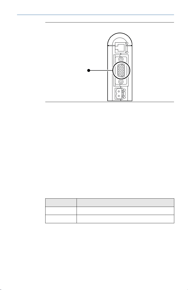
Figure 1-5: Modbus serial connector on the EtherNet/IP module
See Modbus terminals and Pin assignments (EtherNet/IP Module).
5. Set the configuration dip switches on the EtherNet/IP module as
follows:
• Switches 1–7: Off
• Switch 8: On
The IP addess is set to 192.168.0.1.
6. If you are using a Model 1500, Model 2500, or Series 3000 transmitter,
ensure that the RS-485 terminals are in RS-485 mode.
7. Cycle power to the transmitter and wait 15 seconds before applying
power to the EtherNet/IP Module.
8. Power up the EtherNet/IP Module.
The module will attempt to make a Modbus connection to the
transmitter.
9. Is the Subnet Status LED (LED 5) green?
Option
Description
Yes Continue with these steps.
No See LED indicators.
10. Set the network settings for the EtherNet/IP Module.
a) Change the Ethernet address setting for your PC so that it is on
the same subnet as the device. When prompted, enter the
following:
• IP address: 192.168.0.x, where x is something other
than 1
Quick Start Guide 5
Page 6

Quick Start Guide January 2019
• Subnet mask: 255.255.255.0
b) Disable the popup blocker on your web browser.
c) Use a crossover cable (or a standard cable with a switch) and
your web browser to connect to the device, using the IP
address assigned in Step 6: 192.168.0.1.
d) At the login screen, log in as user admin. The default password
is admin. Ignore the auto-configuration popup window.
e) On the Network Settings page, change the settings as
required, and close the web browser.
f) At the EtherNet/IP Module, set all dip switches to Off.
g) Cycle power to the EtherNet/IP Module.
11. Connect the EtherNet/IP Module to the Ethernet network.
See Ethernet connector.
12. Wait for the auto-configuration process to complete.
Important
For initial startup, you must use the auto-configuration process to
ensure that device memory is completely set up.
13. Add the EtherNet/IP Module to the Ethernet network control system.
The EDS file is available on the Resource CD, the EtherNet/IP Module
(download from Administration page), and the Emerson web site.
Postrequisites
For more information on transmitter installation and wiring, see your
transmitter installation manual. For information on configuring the RS-485
terminals and making an RS-485 connection, see your transmitter
configuration manual.
1.4.1 Modbus terminals
Transmitter RS-485/A RS-485/B
Model 1500 33 34
Model 1700 with analog outputs 5 6
Model 2500 33 34
Model 2700 with analog outputs 5 6
Model 3500 with screw-type or solder-tail
terminals
Model 3500 with I/O cables 25 24
Model 3700 12 11
6 Micro Motion EtherNet/IP Module
32a 32b
Page 7
January 2019 Quick Start Guide
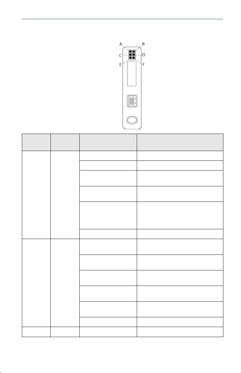
1.4.2 LED indicators
LED
Name Status Description
number
A
Module
Status
(EtherNet)
B
Network
Status
(EtherNet)
C Link Off The module does not sense a link.
Off No power applied to the module.
Solid green The module is operating correctly.
Flashing green Standby. The module has not been
initialized.
Flashing red Minor fault. The module may or may
not be able to recover.
Solid red Major fault. No recovery is possible. The
module must be retuned to Micro
Motion for repair. See the manual for
the return policy.
Flashing green/red Self-test.
Off The module has not power or no IP
address has been assigned.
Solid green The module has at least one
established EtherNet/IP connection.
Flashing green There are no EtherNet/IP connections
established to the module.
Flashing red One or more of the connections to this
module has timed out.
Solid red The module has detected that its IP
address is already in use.
Flashing green/red Self-test.
Quick Start Guide 7
Page 8

Quick Start Guide January 2019
LED
Name Status Description
number
Green The module is connected to an
D Activity Flashing green Packet is received or transmitted.
E
Subnet
Status
(Modbus
Off Power off.
Flashing green Running correctly, but one or more
Serial)
Green Running.
Red Transaction error/timeout or network
Flashing red Missed transactions.
F
Device
Status
(Modbus
Serial)
Off Power off.
Flashing red/green Configuration missing or invalid.
Red Contact customer service.
Flashing red Contact customer service.
Green Initializing.
Flashing green Configuration OK.
Ethernet network.
transaction errors has occurred.
stopped. Check the Modbus serial
network wiring and configuration,
especially the baud.
8 Micro Motion EtherNet/IP Module
Page 9

January 2019 Quick Start Guide
Quick Start Guide 9
Page 10

Quick Start Guide January 2019
10 Micro Motion EtherNet/IP Module
Page 11

January 2019 Quick Start Guide
Quick Start Guide 11
Page 12

*MMI-20019807*
Quick Start Guide
MMI-20019807, Rev. AD
January 2019
Micro Motion Inc. USA
Worldwide Headquarters
7070 Winchester Circle
Boulder, Colorado USA 80301
T +1 303-527-5200
T +1 800-522-6277
F +1 303-530-8459
www.emerson.com
Micro Motion Asia
Emerson Automation Solutions
1 Pandan Crescent
Singapore 128461
Republic of Singapore
T +65 6363-7766
F +65 6770-8003
©
2019 Micro Motion, Inc. All rights reserved.
The Emerson logo is a trademark and service mark of Emerson Electric Co.
Micro Motion, ELITE, ProLink, MVD and MVD Direct Connect marks are
marks of one of the Emerson Automation Solutions family of companies.
All other marks are property of their respective owners.
Micro Motion Europe
Emerson Automation Solutions
Neonstraat 1
6718 WX Ede
The Netherlands
T +31 (0) 70 413 6666
F +31 (0) 318 495 556
www.micromotion.nl
Micro Motion United Kingdom
Emerson Automation Solutions
Emerson Process Management Limited
Horsfield Way
Bredbury Industrial Estate
Stockport SK6 2SU U.K.
T +44 0870 240 1978
F +44 0800 966 181
 Loading...