

Page 1

Product Data Sheet
Micro Motion™ ELITE™ Coriolis Flow and
Density Meters
PS-00374, Rev AK
January 2020
Ultimate real world performance
■
Unchallengeable ELITE performance on liquid mass flow, volume flow, and density
measurements
■
Best-in-class gas mass flow measurement
■
Reliable two-phase flow measurement for the most challenging applications
■
Designed to minimize process, mounting, and environmental effects
Best fit-for-application
■
Scalable platform for the widest range of line size and application coverage including hygienic,
cryogenic, high pressure, and high temperature
■
Available with the broadest range of communication and connectivity options
Superior measurement confidence
■
Smart Meter Verification™ delivers complete, traceable calibration verification, continuously or ondemand at the press of a button
■
Globally leading ISO/IEC 17025 calibration facilities offers best in class uncertainty of ±0.014%
■
Intelligent sensor design mitigates the need for zero calibration in the field
VIEW PRODUCT >
Page 2

ELITE Series Coriolis Flow and Density Meters
January 2020
Micro Motion ELITE Coriolis flow and density meters
ELITE meters provide unmatched flow and density measurement performance to deliver the ultimate control and confidence in
your most complex and challenging liquid, gas, and slurry applications.
Ultimate flow measurement solutions for your unique application requirements
■
Able to achieve the best fit for your flow measurement with a wide range of tube designs and flow rate coverage to best serve
your application
■
Peak performance in a drainable design with a variety of industry approvals for use in strictly governed or regulated applications
■
Scalable platform for a broad array of application coverage including hygienic, cryogenic, high temperature, and high pressure
Smart Meter Verification™: advanced diagnostics for your entire system
■
Included as standard, with the option to license flow range detection and other advanced meter health diagnostics
■
A comprehensive test that can be scheduled, run locally, or from the control room to provide confidence in your meter
functionality and performance
■
Verifies that your meter performs as well as the day it was installed, giving you assurance in less than 90 seconds
■
Saves significant expenditure by reducing labor and extending or eliminating calibration intervals without interrupting the
process
Industry-leading capabilities that unleash your process potential
■
Available with the most extensive offering of transmitter and mounting options for maximum compatibility with your system
■
State of the art, ISO-IEC 17025 compliant calibration stands achieving ±0.014% uncertainty drive best in class measurement
accuracy
■
The most robust communication protocol offering in the industry including Smart Wireless
■
True multivariable technology measures flow, density, and process temperature simultaneously
■
Widest selection of safety, country, and custody transfer approvals
Unparalleled performance in two-phase flow conditions
■
Featuring the lowest frequency Coriolis sensors that ensure the two-phase mixture vibrates with the tube to drastically reduce
uncertainty contributions from both the presence of liquid in a gas flow measurement, and entrained gas or aeration in liquid
flow
■
Unmatched MVD™ transmitter technology with digital signal processing (DSP) delivers the fastest response and refresh rates
enabling accurate batch and other two-phase flow measurement
■
Advanced software options for improved long-term flow reporting of concentration, net oil, and/or Gas Void Fraction (GVF)
during two-phase flow conditions
2 www.emerson.com
Page 3

January 2020
ELITE Series Coriolis Flow and Density Meters
Measurement principles
As a practical application of the Coriolis effect, the Coriolis mass flow meter operating principle involves inducing a vibration of the
flow tube through which the fluid passes. The vibration, though it is not completely circular, provides the rotating reference frame
which gives rise to the Coriolis effect. While specific methods vary according to the design of the flow meter, sensors monitor and
analyze changes in frequency, phase shift, and amplitude of the vibrating flow tubes. The changes observed represent the mass
flow rate and density of the fluid.
Mass and volume flow measurement
The measuring tubes are forced to oscillate producing a sine wave. At zero flow, the two tubes vibrate in phase with each other.
When flow is introduced, the Coriolis forces cause the tubes to twist resulting in a phase shift. The time difference between the
waves is measured and is directly proportional to the mass flow rate. Volume flow rate is calculated from mass flow rate and the
density measurement.
Watch this video to learn more about how a Coriolis flow meter measures mass flow and density (click the link and select View
Videos): https://www.emerson.com/en-us/automation/measurement-instrumentation/flow-measurement/coriolis-flow-meters.
A. Inlet pickoff displacement
B. No flow
C. Outlet pickoff displacement
D. Time
E. Inlet pickoff displacement
F. With flow
G. Outlet pickoff displacement
H. Time difference
I. Time
Density measurement
The measuring tubes are vibrated at their natural frequency. A change in the mass of the fluid contained inside the tubes causes a
corresponding change to the tube natural frequency. The frequency change of the tube is used to calculate density.
www.emerson.com 3
Page 4

ELITE Series Coriolis Flow and Density Meters January 2020
Temperature measurement
Temperature is a measured variable that is available as an output. The temperature is also used internal to the sensor to
compensate for temperature influences on Young’s Modulus of Elasticity.
Meter characteristics
■
Measurement accuracy is a function of fluid mass flow rate independent of operating temperature, pressure, or composition.
However, pressure drop through the sensor is dependent upon operating temperature, pressure, and fluid composition.
■
Specifications and capabilities vary by model and certain models may have fewer available options. For detailed information
regarding performance and capabilities, either contact customer service or visit www.emerson.com/flowmeasurement.
■
All meters with the CMF designation (CMF, CMFHC, CMFS) are members of the ELITE meter family and should be considered to
possess the same qualities and specifications as other ELITE family meters unless specifically noted.
■
The letter at the end of the base model code (for example, CMF100M) represents wetted part material and/or application
designation: M = 316L stainless steel, L = 304L stainless steel, H = nickel alloy C22, P = high pressure, A = high temperature 316L
stainless steel, B = high temperature nickel alloy C22, Y = super duplex (UNS S32750). Detailed information about the complete
product model codes are described later in this document.
Performance specifications
Reference operating conditions
For determining the performance capabilities of our meters, the following conditions were observed / utilized:
■
Water at 68 °F (20 °C) to 77 °F (25 °C) and 14.5 psig (1.000 barg) to 29 psig (2.00 barg)
■
Air and natural gas at 68 °F (20 °C) to 77 °F (25 °C) and 500 psig (34 barg) to 1,450 psig (100 barg)
■
Accuracy based on industry leading accredited calibration standards according to ISO 17025/IEC 17025
■
A density range up to 5 g/cm³ (5,000 kg/m³) on all models
Accuracy and repeatability
Accuracy and repeatability on liquids and slurries
Performance specification
Mass/volume flow accuracy
Mass/volume flow repeatability 0.025% of rate 0.05% of rate
Density accuracy
Density repeatability 0.0001 g/cm³ (0.1 kg/m³) 0.0002 g/cm³ (0.2 kg/m³)
(1)
Not available on all models
(2)
For cryogenic applications with process temperatures below -148 °F (-100.0 °C), the liquid mass flow accuracy is ±0.35% of rate, mass flow
linearity is ±0.05% of rate, and density accuracy specification does not apply.
(3)
Stated flow accuracy includes the combined effects of repeatability, linearity, hysteresis, orientation and other non-linearities.
(4)
The standard density accuracy option for CMFS007, CMFS010, and CMFS015 is ±0.002 g/cm³ (±2 kg/m³). The premium density accuracy option
for CMFS010 and CMFS015 is ±0.0005 g/cm³ (±0.5 kg/m³).
(2)(4)
(2)(3)
Premium option
±0.05% of rate ±0.10% of rate
±0.0002 g/cm³ (±0.2 kg/m³) ±0.0005 g/cm³ (±0.5 kg/m³)
(1)
Standard option
4 www.emerson.com
Page 5

January 2020 ELITE Series Coriolis Flow and Density Meters
Accuracy and repeatability on gases
Performance specification Standard models
Mass flow accuracy
Mass flow repeatability 0.20% of rate
Mass flow linearity ±0.05% of rate up to a 0.2 Mach number
(1)
±0.25% of rate
Accuracy with gas calibration
linearization
(1)
Stated flow accuracy includes the combined effects of repeatability, linearity, hysteresis, orientation and other non-linearities.
(2)
Gas calibration at a third-party gas lab can either be managed by the customer after meter delivery or requested as part of the quote process.
PWL and gas calibration specification reflects expected AS-LEFT linearized results relative to the gas lab reference standards. Actual results may
vary depending on the uncertainty and stability of the gas lab reference standards applied.
(2)
±0.1% of rate after Piecewise Linearization (PWL) adjustment
Accuracy and repeatability on temperature
Performance specification Standard models
Temperature accuracy ±1 °C ±0.5% of reading; BS1904 Class, DIN43760 Class A (±0.15 +0.002 x T °C)
Temperature repeatability 0.2 °C
Environmental temperature
compensation
(1)
Not available on all models.
(1)
BS1904 Class, DIN 43760 Class B (±0.30 + 0.005 x T °C) - Qty 3 case sensors
Warranty
Warranty options on all ELITE models
The warranty period is generally initiated from the day of shipment. For warranty details, see the Terms and Conditions included with
the standard product quote.
Base model
Included as standard Included with startup service Available for purchase
CMF, CMFS, and CMFHC 18 months 36 months > 36 months (customizable
length)
Liquid flow rates
Nominal flow rate
Micro Motion uses the term nominal flow rate. Nominal flow rate is the flow rate at which water at reference conditions causes
approximately 14.5 psig (1.000 barg) of pressure drop across the meter.
Mass flow rates for stainless steel models: 304L (L), 316L (M/A), and super duplex (Y)
Style
Model
CMFS007M 0.08 DN1 1.28 35.0 1.50 40.9
CMFS010M 0.1 DN2 3.56 97.0 4.03 110
CMFS015M 0.17 DN3 11.4 310 12.1 330
www.emerson.com 5
Nominal line size Nominal flow rate Maximum flow rate
inch mm lb/min kg/h lb/min kg/h
Page 6

ELITE Series Coriolis Flow and Density Meters January 2020
Style Model
CMFS025M 0.25 DN6 41 1116 77.0 2100
CMFS040M 0.38 DN10 85.0 2,320 170 4,640
CMFS050M 0.5 DN15 133 3,614 250 6,820
CMFS075M 0.75 DN20 230 6,270 460 12,500
CMFS100M 1 DN25 534 14,524 950 25,900
CMFS150M 1.5 DN40 990 27,000 1,980 54,000
CMF010M/L 0.1 DN2 3.43 93.5 3.96 108
CMF025M/L 0.25 DN6 48.0 1,310 79.9 2,180
CMF050M/L 0.5 DN15 151 4,121 249 6,800
CMF100M/L 1 DN25 602 16,372 997 27,200
CMF200M/L/A 2 DN50 1,760 47,900 3,190 87,100
CMF300M/L/A 3 DN80 6,017 163,755 9,970 272,000
CMF350M/A 4 DN100 10,837 294,931 15,000 409,000
CMF400M/A 4 to 6 DN100-
CMFHC2M/Y 6 to 8 DN150-
Nominal line size Nominal flow rate Maximum flow rate
inch mm lb/min kg/h lb/min kg/h
15,255 415,179 20,000 545,000
DN150
33,224 904,211 54,000 1,470,000
DN200
CMFHC3M/Y 8 to 10 DN200-
DN250
CMFHC4M 10 to 14 DN250-
DN350
58,949 1,604,333 94,000 2,550,000
87,799 2,389,527 120,000 3,266,000
Mass flow rates for nickel alloy C22 (H/B) and high pressure (P) models
Style
Model
CMFS010H/P 0.1 DN2 2.86 78.0 4.03 110
CMFS015H/P 0.17 DN3 8.18 223 12.1 330
CMFS025H/P 0.25 DN6 35.0 945 65.0 1,770
CMFS050H/P 0.5 DN15 100.0 2,720 188 5,130
CMFS100H/P 1 DN25 482 13,125 860 23,500
CMFS150H/P 1.5 DN40 900 24,500 1,800 49,100
CMF010H/P 0.1 DN2 2.57 70.2 3.96 108
CMF025H 0.25 DN6 48 1,310 79.9 2,180
CMF050H 0.5 DN15 151 4,121 249 6,800
Nominal line size Nominal flow rate Maximum flow rate
inch mm lb/min kg/h lb/min kg/h
CMF100H 1 DN25 602 16,372 997 27,200
6 www.emerson.com
Page 7

January 2020 ELITE Series Coriolis Flow and Density Meters
Style Model
CMF200H/B 2 DN50 1,760 47,900 3,190 87,100
CMF300H/B 3 DN75 6017 163,755 9,970 272,000
CMF350P 4 DN100 10,837 294,931 15,000 409,000
CMF400H/B/P 4 - 6 DN100-
Nominal line size Nominal flow rate Maximum flow rate
inch mm lb/min kg/h lb/min kg/h
15,255 415,179 20,000 545,000
DN150
Volume flow rates for stainless steel models: 304L (L), 316L (M/A), and super duplex (Y)
Style Model
gal/min barrels/h l/h gal/min barrels/h l/h
CMFS007M 0.154 0.220 35.0 0.180 0.257 40.9
CMFS010M 0.426 0.609 97.0 0.484 0.691 110
CMFS015M 1.36 1.95 310 1.45 2.07 330
CMFS025M 5 7 1,119 9.23 13.2 2,100
CMFS040M 10.2 14.6 2,320 20.4 29.1 4,640
CMFS050M 16.0 23 3,627 30.0 42.8 6,820
CMFS075M 27.6 39.4 6,270 55.2 78.8 12,500
Nominal flow rate Maximum flow rate
CMFS100M 64.0 91.0 14,576 114 163 25,900
CMFS150M 119 170 27,000 237 339 54,000
CMF010M/L 0.411 0.587 93.5 0.475 0.678 108
CMF025M/L 5.76 8.23 1,310 9.58 13.7 2,180
CMF050M/L 18.0 26.0 4,136 29.9 42.7 6,800
CMF100M/L 72.0 103.0 16,430 120 171 27,200
CMF200M/L/A 211 301 47,900 383 547 87,100
CMF300M/L/A 721 1,029 164,338 1,200 1,710 272,000
CMF350M/A 1,298 1,852 295,981 1,800 2,570 409,000
CMF400M/A 1,827 2,608 416,657 2,400 3,420 545,000
CMFHC2M/Y 3,978 5679 907,429 6,440 9,200 1,470,000
CMFHC3M/Y 7,059 10,077 1,610,044 11,270 16,100 2,550,000
CMFHC4 10,514 15,008 2,398,033 14,350 20,500 3,266,000
www.emerson.com 7
Page 8

ELITE Series Coriolis Flow and Density Meters
Volume flow rates for nickel alloy C22 (H/B) and high pressure (P) models
January 2020
Style Model
CMFS010H/P 0.343 0.490 78.0 0.484 0.691 110
CMFS015H/P 0.980 1.40 223 1.45 2.07 330
CMFS025H/P 4 6 948 7.79 11.1 1,770
CMFS050H/P 12 17 2,729 22.5 32.2 5,130
CMFS100H/P 58 82 13,171 103 147 23,500
CMFS150H/P 108 154 24,500 216 308 49,100
CMF010H/P 0.309 0.441 70.2 0.475 0.678 108
CMF025H 5.76 8.23 1,310 9.58 13.7 2,180
CMF050H 18 26 4,136 29.9 42.7 6,800
CMF100H 72 103 16,430 120 171 27,200
CMF200H/B 211 301 47,900 383 547 87,100
CMF300H/B 721 1,029 164,338 1,200 1,710 272,000
CMF350P 1,298 1,852 295,981 1,800 2,570 409,000
CMF400H/B/P 1,827 2,608 416,657 2,400 3,420 545,000
Nominal flow rate Maximum flow rate
gal/min barrels/h l/h gal/min barrels/h l/h
Gas flow rates
When selecting sensors for gas applications, pressure drop and turndown through the sensor is dependent upon operating
temperature, pressure, and fluid composition. Therefore, when selecting a sensor for any particular gas application, it is highly
recommended that each sensor be sized using the sizing and selection tool at www.emerson.com/flowmeasurement that will
report both the actual velocity and the sonic velocity for each flow rate and meter size considered.
Use the following equation to determine general recommendations on nominal and maximum gas mass flow rates:
=%M*ρ
ṁ
(gas)
ṁ
(gas)
%M
ρ
(gas)
VOS
D
Note
Gas maximum flow rate can never be greater than the maximum liquid rate. Assume that the lower of the two rates is applicable.
Gas mass flow rate
Use Mach number “0.2” for calculating typical nominal rate; use Mach number “0.3” for calculating maximum
recommended rate. When Mach Numbers are above 0.3, most gas flows become compressible and significant
increases in pressure drop may occur regardless of measurement device.
Gas density at operating conditions
Velocity of Sound of the measured gas
Internal diameter of the measuring tube
For a complete list of sensor tube IDs, see the Micro Motion ELITE Coriolis Flow and Density Meters Technical Data
Sheet.
(gas)
*VOS*
1
π*D2 * 2(forsensorswithdual‐tubedesign)
4
8 www.emerson.com
Page 9

60.1
30:1
10:1
2:1
B
A
C
0.1
0
0
10 20
30
40
50
60
70 80
90
100
0.5
0.4
0.3
0.2
4.0
0
20.0
16.0
12.0
8.0
January 2020 ELITE Series Coriolis Flow and Density Meters
Sample calculation
The following calculation is an example of the maximum recommended gas mass flow rate for a CMF300M measuring natural gas
with a molecular weight of 19.5 at 60 °F (16 °C) and 500 psig (34.47 barg):
=0.3*24(kg/m3)*430(m/s)*
ṁ
(gas)
=34,988kg/hr;maximumrecommendedrateforCMF300Mwithnaturalgasatgivenconditions
ṁ
(gas)
1
π * .0447m2 * 2
4
%M
Gas density
VOS
(NG)
CMF300M tube
0.3 (used for calculating maximum recommended rate)
24 kg/m3
430 m/s (Velocity of Sound of natural gas at given conditions)
44.7 mm
ID
Zero stability
Zero stability is used when the flow rate approaches the low end of the flow range where the meter accuracy begins to deviate from
the stated accuracy rating, as depicted in the turndown section. When operating at flow rates where meter accuracy begins to
deviate from the stated accuracy rating, accuracy is governed by the formula: accuracy = (zero stability/flow rate) x 100%.
Repeatability is similarly affected by low flow conditions.
Turndown
The graph and table below represent an example of the measurement characteristics under various flow conditions. At flow rates
requiring large turndowns (greater than 30:1), the zero stability values may begin to govern capability dependent upon flow
conditions and meter in use.
A. Accuracy, % (blue line)
B. Flow rate, % of nominal
C. Pressure drop; psig, barg (red line)
Sample of accuracy and pressure drop across flow rate
Turndown from
nominal flow rate
Accuracy ±% 0.25 0.05 0.05 0.05 0.05
Pressure drop 0.008 psig
www.emerson.com 9
60:1 30:1 10:1 2:1 1:1
(0.00055 barg)
0.06 psig
(0.0041 barg)
0.22 psig
(0.0152 barg)
4.11 psig
(0.2834 barg)
14.5 psig
(1.000 barg)
Page 10

ELITE Series Coriolis Flow and Density Meters January 2020
Zero stability for stainless steel models: 316L (M)
Model
lb/min kg/h
CMFS007M 0.000043 0.0012
CMFS010M 0.000075 0.0020
CMFS015M 0.00030 0.0081
CMFS025M 0.00065 0.017
CMFS040M 0.0018 0.05
CMFS050M 0.0026 0.07
CMFS075M 0.0071 0.19
CMFS100M 0.012 0.33
CMFS150M 0.030 0.81
Zero stability
Zero stability for stainless steel models: 304L (L), 316L (A), and super duplex (Y)
Model
lb/min kg/h
CMF010M/L 0.000078 0.0021
CMF025M/L 0.0010 0.027
Zero stability
CMF050M/L 0.0029 0.078
CMF100M/L 0.017 0.47
CMF200M/L/A 0.048 1.30
CMF300M/L/A 0.16 4.40
CMF350M/A 0.31 8.30
CMF400M/A 0.72 19.71
CMFHC2M/Y/A 1.08 29.45
CMFHC3M/Y/A 2.34 63.56
CMFHC4M 3.66 99.65
Zero stability values for nickel alloy C22 models (H/B)
Model
lb/min kg/h
CMFS010H 0.00016 0.0044
CMFS015H 0.00042 0.011
CMFS025H 0.0013 0.036
CMFS050H 0.0037 0.10
Zero stability
CMFS100H 0.012 0.32
CMFS150H 0.035 0.96
10 www.emerson.com
Page 11

January 2020 ELITE Series Coriolis Flow and Density Meters
Model
lb/min kg/h
CMF010H 0.000075 0.0021
CMF025H 0.00090 0.025
CMF050H 0.0041 0.11
CMF100H 0.014 0.37
CMF200H/B 0.07 1.97
CMF300H/B 0.17 4.57
CMF400H/B 0.74 20.20
Zero stability
Zero stability values for high pressure (P) models
Model
lb/min kg/h
CMFS010P 0.00017 0.0045
CMFS015P 0.00044 0.012
CMFS025P 0.0011 0.031
CMFS050P 0.0043 0.12
Zero stability
CMFS100P 0.012 0.34
CMFS150P 0.030 0.82
CMF010P 0.00016 0.0043
CMF350P 0.32 8.75
CMF400P 0.74 20.07
Process pressure ratings
Sensor maximum working pressure reflects the highest possible pressure rating for a given sensor. Process connection type and
environmental and process fluid temperatures may reduce the maximum rating. For common sensor and fitting combinations, see
the Micro Motion ELITE Coriolis Flow and Density Meters Technical Data Sheet at www.emerson.com/flowmeasurement.
All sensors comply with Council Directive 2014/68/EU on pressure equipment.
Some sensor models also comply with the ASME® B31.1 power piping design code as indicated with a pressure rating in the table.
Sensors with JIS process connections do not comply with ASME B31.1 power piping code.
Sensor maximum working pressure for stainless steel models: 304L (L) and 316L (M/A)
Model
CMFS007M, CMFS010M 3,625 psig (249.93 barg) n/a
CMFS015M 2,225 psig (153.41 barg) n/a
ASME B31.3 compliance ASME B31.1 compliance
CMFS025M, CMFS040M, CMFS050M,
CMFS075M, CMFS100M, CMFS150M
CMF010M/L 1,812 psig (124.93 barg) 1,812 psig (124.93 barg)
1,500 psig (103.42 barg) 1,500 psig (103.42 barg)
www.emerson.com 11
Page 12
ELITE Series Coriolis Flow and Density Meters January 2020
Model ASME B31.3 compliance ASME B31.1 compliance
CMF025M/L, CMF050M/L 1,500 psig (103.42 barg) 1,500 psig (103.42 barg)
CMF100M/L 1,450 psig (99.97 barg) 1,450 psig (99.97 barg)
CMF200M/L/A 1,580 psig (108.94 barg) 1,580 psig (108.94 barg)
CMF300M/L/A 1,730 psig (119.28 barg) 1,730 psig (119.28 barg)
CMF350M/A 1,480 psig (102.04 barg) 1,480 psig (102.04 barg)
CMF400M/A 1,500 psig (103.42 barg) 1,500 psig (103.42 barg)
CMFHC2M/A 1,480 psig (102.04 barg) 1,470 psig (101.35 barg)
CMFHC3M/A 1,480 psig (102.04 barg) 1,460 psig (100.66 barg)
CMFHC4M 1,480 psig (102.04 barg) n/a
Sensor maximum working pressure for nickel alloy C22 models (H/B)
Model ASME B31.3 compliance ASME B31.1 compliance
CMFS010H, CMFS015H 6,000 psig (413.69 barg) n/a
CMFS025H, CMFS050H 3,626 psig (250.00 barg) 3,626 psig (250.00 barg)
CMFS100H, CMFS150H 3,626 psig (250.00 barg) n/a
CMF010H 3,263 psig (224.98 barg) n/a
CMF025H 2,755 psig (189.95 barg) n/a
CMF050H 2,683 psig (184.99 barg) n/a
CMF100H 2,465 psig (169.96 barg) n/a
CMF200H/B 2,755 psig (189.95 barg) n/a
CMF300H/B 2,683 psig (184.99 barg) n/a
CMF400H/B 2,855 psig (196.85 barg) n/a
Sensor maximum working pressure for high pressure models (P)
Model
CMFS010P, CMFS015P 6,000 psig (413.69 barg) n/a
CMFS025P, CMFS050P 3,626 psig (250.00 barg) 3,626 psig (250.00 barg)
CMFS100P, CMFS150P 3,626 psig (250.00 barg) n/a
CMF010P 6,000 psig (413.69 barg) n/a
CMF350P 2,250 psig (155.13 barg) n/a
CMF400P 2,973 psig (204.98 barg) n/a
ASME B31.3 compliance ASME B31.1 compliance
Sensor maximum working pressure for super duplex models (Y)
Model
CMFHC2Y, CMFHC3Y 2,320 psig (159.96 barg) n/a
ASME B31.3 compliance ASME B31.1 compliance
12 www.emerson.com
Page 13
January 2020
ELITE Series Coriolis Flow and Density Meters
Case pressure
Case pressure for CMF models
Model Case maximum pressure
CMF010 425 psig (29.30 barg) 3,042 psig (209.74 barg)
CMF025 850 psig (58.61 barg) 5,480 psig (377.83 barg)
CMF050 850 psig (58.61 barg) 5,286 psig (364.46 barg)
CMF100 625 psig (43.09 barg) 3,299 psig (227.46 barg)
CMF200 550 psig (37.92 barg) 2,786 psig (192.09 barg)
CMF300 275 psig (18.96 barg) 1,568 psig (108.11 barg)
CMF350 275 psig (18.96 barg) 2,092 psig (144.24 barg)
CMF400 250 psig (17.24 barg) 1,556 psig (107.28 barg)
CMFHC2 n/a 1,100 psig (75.84 barg)
CMFHC3 n/a 1,150 psig (79.29 barg)
CMFHC4 n/a 990 psig (68.26 barg)
(1)
Typical burst pressure
(2)
(1)
Derived from B31.3 international standards.
(2)
Values do not apply for high-temperature models (base model codes A or B).
Case pressure for CMFS models
Model
CMFS007 1,326 psig (91.42 barg) 5,302 psig (365.56 barg)
CMFS010, CMFS015 1,518 psig (104.66 barg) 6,072 psig (418.65 barg)
CMFS025, CMFS040, CMFS050 558 psig (38.47 barg) 2,230 psig (153.75 barg)
CMFS075, CMFS100, CMFS150 650 psig (44.82 barg) 2,598 psig (179.13 barg)
(1)
Case maximum pressure is determined by applying a safety factor of 4 to typical burst pressure.
Case maximum pressure
(1)
Typical burst pressure
Operating conditions: Environmental
Vibration limits
Meets IEC 60068-2-6, endurance sweep, 5 to 2000 Hz up to 1.0 g.
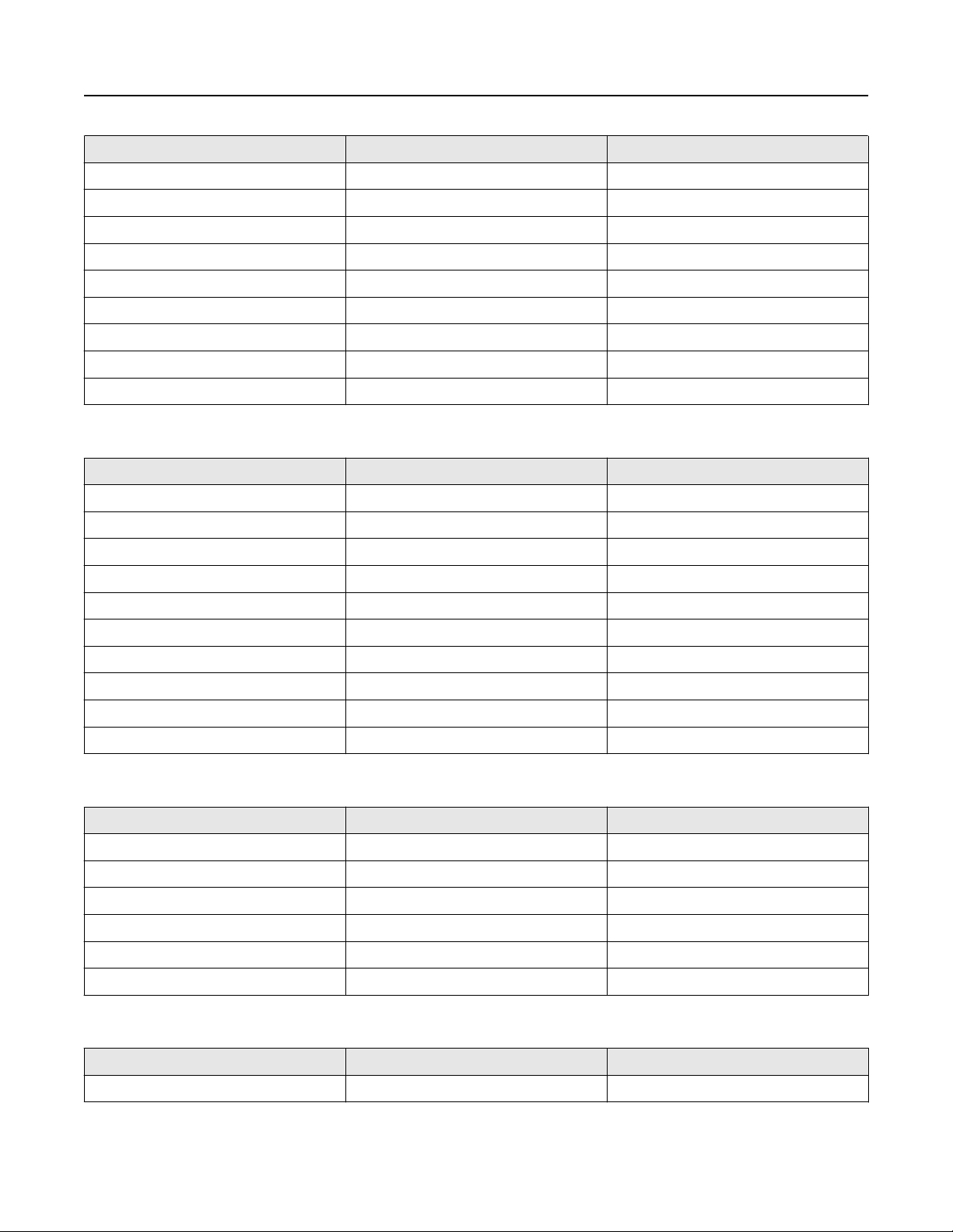
Temperature limits
Sensors can be used in the process and ambient temperature ranges shown in the temperature limit graphs. For the purposes of
selecting electronics options, temperature limit graphs should be used only as a general guide. If your process conditions are close
to the gray area, consult with your Micro Motion representative.
Note
■
In all cases, the electronics cannot be operated where the ambient temperature is below -40 °F (-40.0 °C) or above 140 °F
(60.0 °C). If a sensor is to be used where the ambient temperature is outside of the range permissible for the electronics, the
electronics must be remotely located where the ambient temperature is within the permissible range, as indicated by the
shaded areas of the temperature limit graphs.
www.emerson.com 13
Page 14
140 (60)
–40 (–40)
113
(45)
–148 (–100)
–400
(–240)
400
(204)
140
(60)
T amb
T proc
A
B
B
C
-148
(-100)
ELITE Series Coriolis Flow and Density Meters
■
Temperature limits may be further restricted by hazardous area approvals. Refer to the hazardous area approvals
January 2020
documentation shipped with the sensor or available at www.emerson.com/flowmeasurement.
■
The extended-mount electronics option allows the sensor case to be insulated without covering the transmitter, core
processor, or junction box, but does not affect temperature ratings. When insulating the sensor case at elevated process
temperatures above 140 °F (60.0 °C), ensure electronics are not enclosed in insulation as this may lead to electronics failure.
■
For the CMFS007 sensor, the difference between the process fluid temperature and the average temperature of the case must
be less than 210 °F (99 °C)
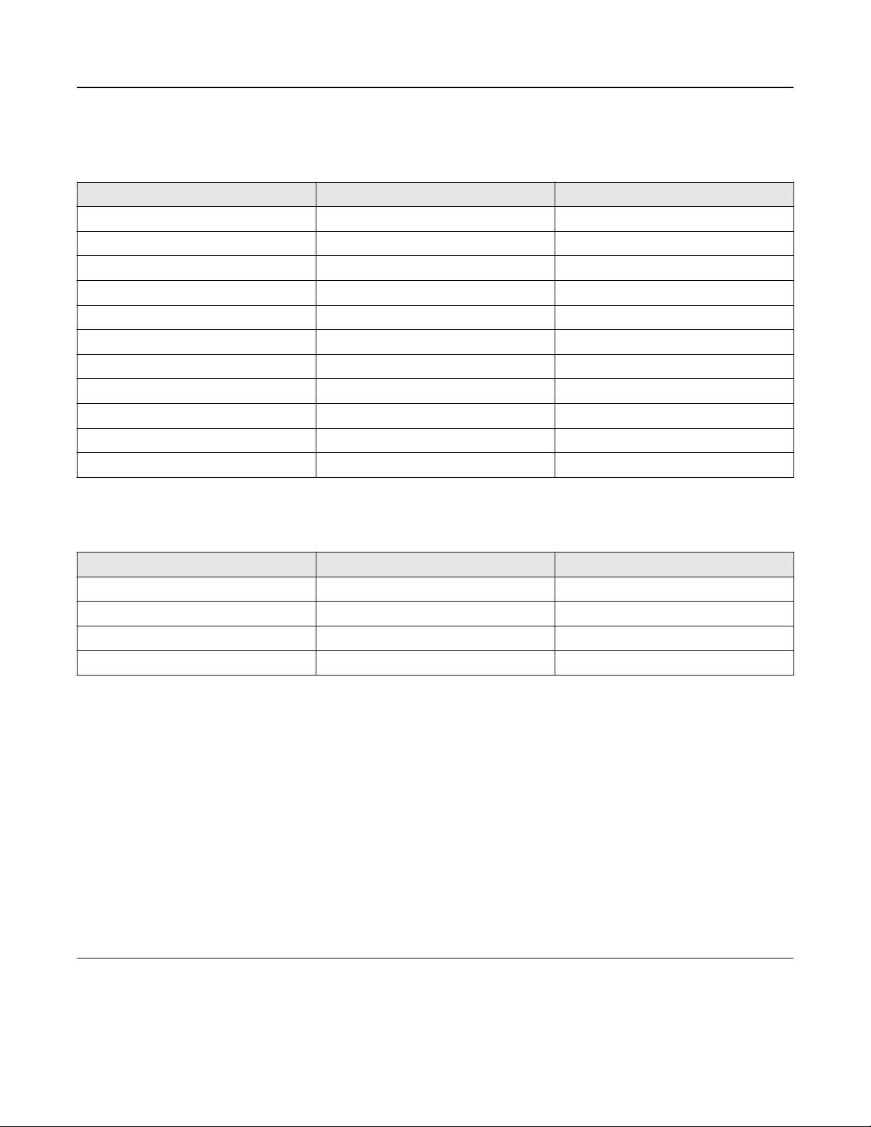
Ambient and process temperature limits for CMFS007, CMFS025–CMFS150
B
113
(45)
Tamb
–40 (–40)
140 (60)
140 (60)
A
B
–148 (–100)
–58 (–50) 400 (204)
T
= Ambient temperature °F (°C)
amb
T
= Process temperature °F (°C)
proc
A = All available electronic options
B= Remote mount electronics only
Ambient and process temperature limits for CMF***M/L/H/P (excludes special order cryogenic modifications)
and CMFS010-015
Tproc
T
= Ambient temperature °F (°C)
amb
T
= Process temperature °F (°C)
proc
A = All available electronic options
B = Remote mount electronics only
C = Recommend special order cryogenic sensor options when operating at a process temperature below -148 °F (-100 °C)
14 www.emerson.com
Page 15

January 2020
ELITE Series Coriolis Flow and Density Meters
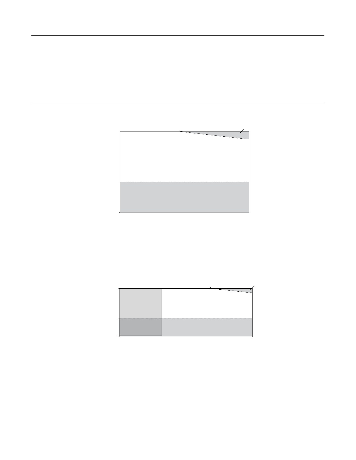
Ambient and process temperature limits for special order cryogenic ELITE meters
140 (60)
Tamb
–40 (–40)
A
B
–148 (–100)
–400
(–240)
T
= Ambient temperature °F (°C)
amb
T
= Process temperature °F (°C)
proc
A = All available electronic options
B= Remote mount electronics only
Ambient and process temperature limits for high temperature ELITE meters
140 (60)
Tproc
176
(80)
Tamb
–40 (–40)
A
B
–148 (–100)
T
= Ambient temperature °F (°C)
amb
T
= Process temperature °F (°C)
proc
A = All available electronic options
B= Remote mount electronics only
Ambient and process temperature limits for super duplex ELITE meters
–58
(–50)
140 (60)
Tamb
–40 (–40)
Tproc
140 (60)
A
B
B
113
(45)
662
(350)
–148 (–100)
T
= Ambient temperature °F (°C)
amb
T
= Process temperature °F (°C)
proc
–40 (–40) 400 (204)
Tproc
A = All available electronic options
B= Remote mount electronics only
Note
For super duplex models operating above 351 °F (177.2 °C), consult the factory before purchase.
www.emerson.com 15
Page 16

ELITE Series Coriolis Flow and Density Meters January 2020
Operating conditions: Process
Process temperature effect
■
For mass flow measurement, process temperature effect is defined as the change in sensor flow accuracy specification due to
process temperature change away from the calibration temperature. Use the Zero Verification and Smart Meter Verification
tools to correct for any process temperature effect.
■
For density measurement, process temperature effect is defined as the change in density accuracy specification due to process
temperature change away from the calibration temperature.
— For all models, process temperature effect on density is ±0.000015 g/cm³ (±0.015 kg/m³) per degree difference from
calibration temperature.
— For models ordered with optional temperature calibration, density specification is valid from 0 °F (-17.8 °C) to 60 °F (15.6 °C)
and process temperature effect should be considered when operating above or below this range.
Flow process temperature effect for all models
Model % of maximum mass flow rate per °C
CMF010, CMFS007, CMFS010, CMFS015 ±0.0002
CMF025, CMF050, CMF100, CMFS025,
CMFS040, CMFS050, CMFS075,
CMFS100, CMFS150
CMF200, CMF300 ±0.0005
CMF350, CMF400 ±0.0008
CMFHC2, CMFHC3, CMFHC4 ±0.000075
±0.0001
Process pressure effect
Process pressure effect is defined as the change in sensor mass flow and density accuracy specification due to process pressure
change away from the calibration pressure. This effect can be corrected by dynamic pressure input or a fixed meter factor. See the
calibration sheet for the specific meter pressure compensation coefficient. If no pressure compensation coefficient is provided, use
the typical values listed in the table below. For proper setup and configuration, see the Micro Motion ELITE Coriolis Flow and Density
Sensors Installation Manual at www.emerson.com/flowmeasurement.
Process pressure effect for CMFS models
Model
CMFS007, CMFS010,
CMFS015
CMFS025 None None –0.000004 –0.054
per psi per bar g/cm3 per psi kg/m3 per bar
None None None None
Mass flow (% of rate) Density
CMFS040 -0.0003 -0.005 –0.0000131 –0.187
CMFS050 M –0.001 –0.015 -0.0000247 –0.358
CMFS050 H/P None None -0.0000034 –0.049
CMFS075 –0.0007 –0.010 -0.0000255 –0.370
CMFS100 M -0.0015 -0.021 -0.0000276 –0.400
CMFS100 H/P -0.0003 -0.005 -0.0000132 –0.191
16 www.emerson.com
Page 17

January 2020
ELITE Series Coriolis Flow and Density Meters
Model
per psi per bar g/cm3 per psi kg/m3 per bar
CMFS150M -0.0014 -0.020 -0.000010 –0.145
CMFS150H/P -0.0004 -0.006 -0.0000062 –0.090
Mass flow (% of rate) Density
Process pressure effect for CMF and CMFHC models
Model
per psi per bar g/cm3 per psi kg/m3 per bar
CMF010 None None None None
CMF025 None None 0.0000040 0.0580
CMF050 None None –0.0000020 –0.0290
CMF100 –0.0002 –0.003 -0.0000060 –0.0870
CMF200 M/A/L -0.00062 –0.009 0.0000010 0.0145
CMF200 H/B -0.00055 –0.008 0.000001 0.0145
CMF300 M/A/L –0.0006 –0.009 0.0000002 0.0029
CMF300 H/B -0.0004 –0.006 0.0000002 0.0029
CMF350 -0.0016 –0.023 -0.000009 –0.1305
Mass flow (% of rate) Density
CMF400 M/A –0.0011 –0.016 -0.00001 –0.1450
CMF400 H/B/P -0.0008 –0.012 -0.00001 –0.1450
CMFHC2 –0.0016 –0.023 –0.0000028 –0.0406
CMFHC3 –0.0010 –0.015 –0.0000025 –0.0363
CMFHC4 –0.0014 –0.020 –0.0000014 –0.0203
Two-phase flow effect
NAMUR NE 132 guidelines state that, “Coriolis meters with a higher agitation frequency react more sensitively to gas bubbles in
liquids when compared to devices with a lower agitation frequency.” For operating (agitation) frequency ranges for each model,
see Best practices: installing and selecting meters for two-phase flow.
Two-phase flow effects are governed by an increased decoupling ratio or a decreased Velocity of Sound (VoS) in the process fluid
due to entrained gas, aeration, or the presence of liquid in gas. Following best practices regarding installation and meter selection
can prevent or minimize measurement errors associated with two-phase flow effects.
Tip
For more details regarding the effects of two-phase flow on Coriolis meters, or performance expectations in these applications, see
the Entrained Gas Handling in Micro Motion Coriolis white paper and any additional resources available at www.emerson.com/
flowmeasurement.
Performance influences during two-phase flow conditions
Optimal meter performance during two-phase flow conditions is primarily governed by meter selection, flow regime, and fluid
properties. Sample magnitudes of the effect are provided in the white paper referenced previously. The information in the
following table provides common forms of influence quantities that can affect measurement performance during two-phase flow
conditions.
www.emerson.com 17
Page 18

ELITE Series Coriolis Flow and Density Meters January 2020
Two-phase flow performance influence factors
Type of influence Specific influence on measurement Recommendation
VoS / fluid compressibility Over-reading due to interaction between
frequency of the acoustic and drive
modes
Decoupling Under-reading as a result of bubble or
particle movement with respect to the
fluid
Signal processing noise Ability to maintain signal accuracy during
high noise conditions or rapid process
changes
(1)
See Operating drive mode frequency range for all models.
Select a meter that operates in an ULTRA-
(1)
LOW
or LOW drive frequency range to
avoid VoS effects.
Increase fluid viscosity, decrease bubble
size, or use a meter with lower drive
frequency in order to minimize
decoupling.
Select advanced electronics that use
high-speed mass and density signal
processing methods for effective noise
rejection.
Best practices: installing and selecting meters for two-phase flow
Flow sensor best practices:
■
Ensure that the meter is sized correctly to maintain a flow rate greater than 5:1 turndown from nominal.
■
Install the meter with the preferred orientation. For orientation based on fluid type, see the Micro Motion ELITE Coriolis Flow and
Density Sensors Installation Manual
■
Select a meter design with the lowest available operating frequency.
Transmitter and electronics best practices:
■
Enable multiphase severity alerts to accurately detect when two-phase flow is present.
■
Select a meter with a real-time clock and historian capabilities to diagnose process events or upsets.
■
Use Advanced Phase Measurement in intermittent high %GVF or %LVF installations where density or volume flow is required.
Operating drive mode frequency range for all models
Reference conditions: water at 14.7 psig (1.014 barg) and 60 °F (16 °C).
ULTRA-LOW (<100 hZ)
LOW (100 - 150 hZ)
MID-RANGE (150 - 300 hZ)
HIGH (> 300 hZ)
Nominal line size
≤ 1 inch
(DN25)
1.5 - 3 inch
(DN50 - 80)
ULTRA-LOW
(< 100 Hz)
CMF010, CMFS010 CMFS007, CMFS015,
CMF200, CMF300 — CMFS150 —
Preferred solution for installations with two-phase flow conditions
Preferred solution for installations with two-phase flow conditions
Suitable in some instances for installations with two-phase flow conditions
Not recommended for two-phase flow installations
Drive mode frequency range and designation
LOW
(100 - 150 Hz)
CMF025, CMFS025,
CMFS040, CMF050,
CMFS075, CMF100
MID-RANGE
(150 - 300 Hz)
CMFS050, CMFS100 —
HIGH
(> 300 Hz)
18 www.emerson.com
Page 19

January 2020
Nominal line size
ULTRA-LOW
(< 100 Hz)
ELITE Series Coriolis Flow and Density Meters
Drive mode frequency range and designation
LOW
(100 - 150 Hz)
MID-RANGE
(150 - 300 Hz)
HIGH
(> 300 Hz)
4 - 6 inch
(DN100 - 150)
≥ 6 inch
(DN150)
HC2, HC3, HC4 — — —
— CMF350, CMF400 — —
Viscosity range
For installations with 4 in (DN100) or larger meters, and fluid viscosities greater than 500 centistokes (cSt), consult your Micro
Motion sales representative or technical support for guidance on optimizing your configuration. This recommendation is not
applicable for smaller meters or processes with viscosities less than 500 cSt.
Pressure relief
ELITE sensors are available with a rupture disk installed on the case. Rupture disks vent process fluid from the sensor case in the
unlikely event of a flow tube breach. Some users connect a pipeline to the rupture disk to help contain escaping process fluid. For
more information about rupture disks, contact customer service.
If the sensor has a rupture disk, keep it installed at all times as it would otherwise be necessary to re-purge the case. If the rupture
disk is activated by a tube breach, the seal in the rupture disk will be broken, and the Coriolis meter should be removed from
service.
WARNING
■
Orient the sensor so that personnel and equipment will not be exposed to any discharge along the pressure relief path.
■
Stay clear of the rupture disk pressure relief area. High-pressure fluid escaping from the sensor can cause severe injury or
death.
Important
If using a rupture disk, the housing can no longer assume a secondary containment function.
NOTICE
Removing the purge fitting, blind plug, or rupture disks compromises the Ex-i Safety Certification, the Ex-tc Safety Certification,
and the IP-rating of the Coriolis meter. Any modification to the purge fitting, blind plug, or rupture disks must maintain a minimum
of IP66/IP67 Ratings.
www.emerson.com 19
Page 20

ELITE Series Coriolis Flow and Density Meters January 2020
Hazardous area classifications
Approvals and certifications
Type Approval or certification (typical)
CSA and CSA C-US Ambient temperature: -40 °F (-40.0 °C) to 140 °F (60.0 °C) Class I, Div. 1, Groups C and
D
Class I, Div. 2, Groups A, B, C, and D. Class II, Div.1, Groups E, F, and G.
ATEX II 2G Ex ib IIB/IIC T1–T4/T5/T6 Gb
II 2D Ex ib IIIC T(1)°C Db IP66
II 3G Ex nA IIC T1–T4/T5 Gc
II 3D Ex tc IIIC T(1) °C Dc IP66
IECEx Ex ib IIB/IIC T1–T4/T5/T6 Gb
Ex nA IIC T1-T4/T5 Gc
NEPSI Ex ib IIB/IIC T1–T6 Gb
Ex ibD 21 T450°C-T85°C Ex nA IIC T1–T6 Gc
DIP A22 T(1) T1-T6
Ingress Protection Rating IP 66/67 for sensors and transmitters
EMC effects Complies with EMC directive 2004/108/EC per EN 61326 Industrial
Complies with NAMUR NE-21 (22.08.2007)
Note
For complete details on hazardous area classifications availability by model code, use the Micro Motion ELITE Coriolis Flow and Density
Meters Technical Data Sheet at www.emerson.com/flowmeasurement.
Marine approval classifications
CMF200M, CMF300M, CMF350M, CMF400M, CMFHC2M, CMFHC3M, and CMFHC4M
Marine approval
Lloyd’s Register ENV1, ENV2, ENV3, ENV5 United Kingdom
Det Norske Veritas- Germanischer Lloyd Norway-Germany
Bureau Veritas France
American Bureau of Shipping USA
Nippon Kaiji Kyokai Japan
CMFS010H, CMFS015H, CMFS025H, CMFS050H, CMFS100H, and CMFS150H
Country
Marine approval
Lloyd’s Register ENV1, ENV2, ENV3, ENV5 United Kingdom
Det Norske Veritas- Germanischer Lloyd Norway-Germany
Country
20 www.emerson.com
Page 21

January 2020
Industry standards
Type Standard
Weights & Measures for custody transfer
applications:
■
MID OIML R117/R137
■
National Type Evaluation Program (NTEP)
■
Measurement Canada
■
INMETRO Brazil
ELITE Series Coriolis Flow and Density Meters
Hygienic approvals (some models)
Industry standards and commercial
approvals
Note
■
Approvals shown are for ELITE meters configured with a core processor for remote 4-wire connection to a Micro Motion
transmitter. Meters with integral electronics may have more restrictive approvals. For details, see the transmitter Product Data
Sheet.
■
When a meter is ordered with hazardous area approvals, detailed information is shipped along with the product.
■
More information about hazardous approvals, including detailed specifications and temperature graphs for all meter
configurations is available on the ELITE Series product page at www.emerson.com/flowmeasurement.
■
ASME BPE
■
EHEDG, 3A
■
NAMUR: NE 132 (burst pressure, sensor flange to flange length), NE131
■
Pressure Equipment Directive (PED)
■
Canadian Registration Number (CRN)
■
Dual Seal
■
ASME B31.1 power piping code and ASME B31.3 process piping code
■
SIL2 and SIL3 safety certifications
■
All Super Duplex materials comply with NORSOK M-650
www.emerson.com 21
Page 22

ELITE Series Coriolis Flow and Density Meters January 2020
Connectivity
ELITE sensors are highly customizable to provide a configuration that is tailor-fit to specific applications.
For help determining which Micro Motion products are right for your application, see the Micro Motion Technical Overview and
Specification Summary and other resources at www.emerson.com/flowmeasurement.
Communication and diagnostic information
Transmitter interface Diagnostic data
■
Up to five fully configurable I/O channels, with options for 2wire, Ethernet, and wireless communication
■
Complete suite of mounting options to accommodate
installation requirements — integral, remote, wall mount,
and DIN rail
■
Application software designed specific for your process —
batching, concentration, and Advanced Phase
Measurement
■
Smart Meter Verification — checks the health and integrity
of the meter's tubes, electronics, and calibration without
interrupting the process
■
Zero verification — quickly diagnoses the meter to
determine if re-zeroing is recommended, and if process
conditions are stable and optimal for zeroing
■
Multiphase detection — proactively identifies multiphase
process conditions and severity
■
Time-stamped digital audit trails and reports for optimized
agency compliance
Communication protocols
Typical I/O connectivity options include:
■
4-20 mA
■
HART
■
10k Hz pulse
■
Wireless
■
Ethernet
22 www.emerson.com
■
Modbus
■
FOUNDATION fieldbus
■
PROFIBUS-PA
■
PROFIBUS-DP
■
Discrete I/O
Page 23

January 2020 ELITE Series Coriolis Flow and Density Meters
Transmitter compatibility and primary attributes
For a complete list of all transmitter configurations and options, see the transmitter product data sheets and other resources
available at www.emerson.com/flowmeasurement.
Model
CMF • • • • • •
CMFS • • • • • • •
CMFHC • • • • •
AC • • • •
DC • • • • • •
Loop powered
(2-wire)
SMV basic
(included)
1500/2500 1700/2700 2400S 3000 series FMT 4200 5700
Flow meters
Diagnostics
• • • • • •
Transmitter
Power
•
SMV Pro • • • • • •
Real time
clock
Onboard data
historian
Local operator interface
2-line display • •
Graphical
display
Certifications and approvals
SIS certified • • •
Custody
transfer
• • •
• • •
• •
• •
www.emerson.com 23
Page 24

ELITE Series Coriolis Flow and Density Meters
January 2020
Physical specifications
Materials of construction
General corrosion guidelines do not account for cyclical stress, and therefore should not be relied upon when choosing a wetted
material for your Micro Motion meter. For material compatibility information, see the Micro Motion Corrosion Guide.
Wetted part materials
Model
316L 316L 32Ra 304L
CMFS007 • 10 lb (5 kg)
CMFS010 • • • 10 lb (5 kg)
CMFS015 • • • 10 lb (5 kg)
CMFS025 • • 19 lb (9 kg)
CMFS040 • 19 lb (9 kg)
CMFS050 • • 19 lb (9 kg)
CMFS075 • 30 lb (14 kg)
CMFS100 • • 30 lb (14 kg)
CMFS150 • • 30 lb (14 kg)
CMF010 • • • 17 lb (8 kg)
CMF025 • • • 9 lb (4 kg)
CMF050 • • • 14 lb (6 kg)
CMF100 • • • 31 lb (14 kg)
CMF200 • • • 66 lb (30 kg)
CMF300 • • • 180 lb (82 kg)
Stainless steel
Nickel alloy C22 Super duplex
Sensor only
weight
CMF350 • • 240 lb (109 kg)
CMF400 • • 440 lb (200 kg)
CMFHC2 • • 610 lb (277 kg)
CMFHC3 • • 770 lb (349 kg)
CHFHC4 • 1,390 lb
(630 kg)
Note
■
Weight specifications are based upon ASME B16.5 CL 150 flange and do not include electronics.
■
Heat jackets and steam kits are also available.
24 www.emerson.com
Page 25

January 2020
Non-wetted part materials
ELITE Series Coriolis Flow and Density Meters
Component Enclosure rating 300 series stainless steel
Sensor housing — •
Core processor housing NEMA 4X (IP66/67) • •
Junction box NEMA 4X (IP66) • •
Transmitter housing
(1)
Material of construction and surface finish options vary by model. For available options, see the transmitter Product Data Sheet.
(1)
NEMA 4X (IP66) • •
Polyurethane-painted
aluminum
Process connections
Sensor type Flange types
Stainless steel 316L & cryogenic
■
ASME B16.5 weld neck flange (up to CL600)
■
ASME B16.5 weld neck flange RTJ face (up to CL600)
■
ASME B16.5 weld neck flange raised face (up to CL600)
■
ASME B16.5 wafer style
■
EN 1092-1 weld neck flange Type B1, B2, C, D, E, N (up to PN100)
■
JIS B2220 weld neck raised face (up to 20K)
■
VCO, VCR Swagelok compatible fitting (VCO fittings include the Viton o-ring as a
wetted part)
■
Hygienic Tri-Clamp® compatible
■
Nickel alloy C22
Nickel alloy C22/316L stainless steel
Hygienic
Note
For flange compatibility, refer to the Sizing and Selection Tool at www.emerson.com/flowmeasurement.
ASME B16.5 lap joint flange (up to CL900/1500)
■
EN 1092-1 lap joint flange Type B, D (up to PN160)
■
JIS B2220 lap joint flange (up to 20K)
■
ASME B16.5 weld neck flange (up to CL2500)
■
VCO swagelok compatible fitting
■
EN 1092-1 weld neck flange Type B, D (up to PN250)
■
Hygienic Tri-Clamp compatible
■
Hygienic fittings (Tri-Clamp ASME BPE)
■
Hygienic couplings (DIN11864-1A/2A/3A; DIN11851; ISO 2852/DIN 11850; ISO
2852/ISO 1127; SMS 1145)
www.emerson.com 25
Page 26

5-1/4
(132)
A
C
B
5-1/4
(132)
B
C
A
D
ELITE Series Coriolis Flow and Density Meters
January 2020
Dimensions
These dimensional drawings are intended to provide a basic guideline for sizing and planning.
■
For Face-to-Face dimensions for ELITE meters with each available process connection, see the Micro Motion ELITE Coriolis Flow
and Density Meters Technical Data Sheet at www.emerson.com/flowmeasurement.
■
For complete and detailed dimensional drawings, see the product drawings link at www.emerson.com/flowmeasurement.
Note
■
Accuracy = ±0.12 in (±3.0 mm)
■
These drawings are representative of a 316 stainless steel model fitted with an ASME B16.5 CL 150 flange, and a 2400 or 5700
transmitter
Example dimensions for CMFS models
Figure 1: CMFS 007, 010, and 015 models
Figure 2: CMFS 025, 040, 050, 075, 100, and 150
26 www.emerson.com
Page 27

7-7/8 (199)
7-13/16
(197)
7-1/8
(181)
9
(229)
1-3/4
(46)
A
B
C
D
E
January 2020 ELITE Series Coriolis Flow and Density Meters
Model
CMFS007M,
CMFS010M,
CMFS015M
CMFS025M,
CMFS040M,
CMFS050M
CMFS075M,
(1)
(1)
Dim. A
ASME B16.5 CL150
12.6 in (320 mm) 8.1 in (206 mm) 4.4 in (112 mm) 2.1 in (53 mm)
19.4 in (493 mm) 9.4 in (239 mm) 7.4 in (188 mm) 3.25 in (82.6 mm)
23.5 in (597 mm) 10.1 in (257 mm) 9.5 in (241 mm) 4 in (102 mm)
CMFS100M,
CMFS150M
CMFS075M,
CMFS100M,
CMFS150M
(1)
Includes all models with the standard 0.5 in (13 mm) flange.
(2)
Includes all models with the standard 1 in (25 mm) flange.
(2)
Example dimensions for the CMF010
Dim. B Dim. C Dim. D
Example dimensions for the CMF025 through CMF100
Model
CMF010M 7.8 in (198 mm) 9 in (229 mm) 7.1 in (180 mm) 7.8 in (198 mm) 1.8 in (46 mm)
CMF025M 6.75 in (171.4 mm) 10 in (254 mm) 8.25 in (209.5 mm) 9.4 in (239 mm) 1.7 in (43 mm)
CMF050M 7.95 in (201.9 mm) 14.4 in (366 mm) 11.1 in (282 mm) 12 in (305 mm) 2 in (51 mm)
CMF100M 9.25 in (235.0 mm) 21.5 in (546 mm) 16 in (406 mm) 16.1 in (409 mm) 3.5 in (89 mm)
www.emerson.com 27
Dim. A
ASME B16.5 CL150
Dim. B Dim. C Dim. D Dim. E
Page 28

A
B
C
E
D
ELITE Series Coriolis Flow and Density Meters January 2020
Example dimensions for CMF200 through CMFHC4
Model
CMF200M 22.9 in (582 mm) 19.61 in (498.1 mm) 6.9 in (175 mm) 28.6 in (726 mm) 5.7 in (145 mm)
CMF300M 33.7 in (856 mm) 30.2 in (767 mm) 9.3 in (236 mm) 38.4 in (975 mm) 8.2 in (208 mm)
CMF350M 37.2 in (945 mm) 28.3 in (719 mm) 12.2 in (310 mm) 32.8 in (833 mm) 8.3 in (211 mm)
CMF400M 40.2 in (1,021 mm) 32.8 in (833 mm) 12.4 in (315 mm) 38.1 in (968 mm) 10.8 in (274 mm)
CMFHC2M 42.8 in (1,087 mm) 33 in (838 mm) 12.32 in (312.9 mm) 48.6 in (1,234 mm) 12.8 in (325 mm)
CMFHC3M 43.7 in (1,110 mm) 33 in (838 mm) 13.2 in (335 mm) 53.1 in (1,349 mm) 14 in (356 mm)
CMFHC4M 47.8 in (1,214 mm) 33 in (838 mm) 14.1 in (358 mm) 65.5 in (1,664 mm) 17.8 in (452 mm)
Dim. A
ASME B16.5 CL150
Dim. B Dim. C Dim. D Dim. E
28 www.emerson.com
Page 29

CMFS025M313N0AMEZZZZMC
A B C D E F G H IJK L M
January 2020 ELITE Series Coriolis Flow and Density Meters
Ordering information
Use this section to select the correct ordering codes for your configuration.
Example model code
The sensor is shipped with a model code stamp so that after purchase, you can verify the ordering codes described in this section.
A. Sensor and model
B. Base model
C. Process connection
D. Case option
E. Electronics interface
F. Conduit connection
G. Approval
H. Language
I. Additional standard approval
J. Calibration
K. Measurement application software
L. Factory options
M. Certificates, tests, calibrations, and services
Process connections
CMFS010H and CMFS015H (nickel alloy C22)
Code
323 #4 VCO N06022 Swagelok compatible fitting 0.25 in (6.4 mm) N10276
334 #4 VCO N06022 Swagelok compatible fitting
520 0.5 in CL150 ASME B16.5 F304/F304L Lap joint flange N06022 stub
521 0.5 in CL300 ASME B16.5 F304/F304L Lap joint flange N06022 stub
522 15 mm 10K JIS B 2220 F304/F304L Lap joint flange N06022 stub
523 DN15 PN40 DIN 2656 F304/F304L Lap joint flange Form C face, N06022 stub
524 DN15 PN40 EN 1092-1 F304/F304L Lap joint flange Type B1, N06022 stub
CMFS007M, CMFS010M, and CMFS015M (316L stainless steel)
Code
172 DN25 PN40 EN 1092-1 F316/F316L Weld neck flange Type B1
176 DN15 PN40 EN 1092-1 F316/F316L Weld neck flange Type B1
177 DN15 PN100 EN 1092-1 F316/F316L Weld neck flange Type B2
Description
NPT female adapter
Description
www.emerson.com 29
Page 30

ELITE Series Coriolis Flow and Density Meters January 2020
Code Description
178 DN15 PN100 EN 1092-1 F316/F316L Weld neck flange Type D
183 DN25 PN40 EN 1092-1 F316/F316L Weld neck flange Type D
300 15 mm PN40 DIN 2635 F316/F316L Weld neck flange Type C
301 15 mm PN40 DIN 2635 F316/F316L Weld neck flange Type N
302 15 mm PN100 DIN 2635 F316/F316L Weld neck flange Type E
303 15 mm PN100 DIN 2635 F316/F316L Weld neck flange Type N
304 15 mm 10K JIS B 2220 F316/F316L Weld neck flange Raised face
305 15 mm 20K JIS B 2220 F316/F316L Weld neck flange Raised face
310 DN15 PN40 EN 1092-1 F316/F316L Weld neck flange Type D
313 0.5 in CL150 ASME B16.5 F316/F316L Weld neck flange Raised face
314 0.5 in CL300 ASME B16.5 F316/F316L Weld neck flange Raised face
315 0.5 in CL600 ASME B16.5 F316/F316L Weld neck flange Raised face
319 #8 VCO 316/316L Swagelok compatible fitting 0.5 in (13 mm) 316 NPT
female adapter
(1)
321
0.5 in Tri-Clamp
compatible
316L Hygienic fitting
323 #4 VCO 316/316L Swagelok compatible fitting 0.25 in (6.4 mm) NPT female
adapter
324 #4 VCO 316/316L Swagelok compatible fitting 0.25 in (6.4 mm) tube
compression fitting adapter
325 #4 VCO 316/316L Swagelok compatible fitting 6 mm tube compression
fitting adapter
334 #4 VCO 316/316L Swagelok compatible fitting
335 #8 VCO 316/316L Swagelok compatible fitting
(2)(3)
344
0.75 in Tri-Clamp
316L Hygienic fitting
compatible
(2) (3)
345
DN10 ISO 2852/ISO
316L Hygienic fitting
1127 tube
(2) (3)
346
DN15 ISO 2852/DIN
316L Hygienic fitting
11850 tube
(1)
3A authorized sensor with process connection code 321 and case option code H.
(2)
3A authorized sensor with process connections codes 344, 345 and 346; and case option code H.
(3)
Process connections 344, 345, 346 are not available for the CMFS007 sensors.
CMFS010P and CMFS015P (nickel alloy C22/316L stainless steel)
Code
150 0.5 in CL900/1500 ASME B16.5 F316/F316L Weld neck flange Raised face
Description
191 0.5 in CL2500 ASME B16.5 F316/F316L Weld neck flange Raised face
319 #8 VCO 316/316L Swagelok compatible fitting 0.5 in (13 mm) 316 NPT
female adapter
30 www.emerson.com
Page 31

January 2020
Code Description
323 #4 VCO 316/316L Swagelok compatible fitting 0.25 in (6.4 mm) NPT female
324 #4 VCO 316/316L Swagelok compatible fitting 0.25 in (6.4 mm) tube
325 #4 VCO 316/316L Swagelok compatible fitting 6 mm tube compression
334 #4 VCO 316/316L Swagelok compatible fitting
335 #8 VCO 316/316L Swagelok compatible fitting
ELITE Series Coriolis Flow and Density Meters
adapter
compression fitting adapter
fitting adapter
CMFS025H and CMFS050H (nickel alloy C22)
Code Description
520 0.5 in CL150 ASME B16.5 F304/F304L Lap joint flange N06022 stub
521 0.5 in CL300 ASME B16.5 F304/F304L Lap joint flange N06022 stub
524 DN15 PN40 EN 1092-1 F304/F304L Lap joint flange Type B1, N06022 stub
CMFS025M, CMFS040M, and CMFS050M (316L stainless steel)
Code
172 DN25 PN40 EN 1092-1 F316/F316L Weld neck flange Type B1
176 DN15 PN40 EN 1092-1 F316/F316L Weld neck flange Type B1
177 DN15 PN100 EN 1092-1 F316/F316L Weld neck flange Type B2
178 DN15 PN100 EN 1092-1 F316/F316L Weld neck flange Type D
183 DN25 PN40 EN 1092-1 F316/F316L Weld neck flange Type D
304 15 mm 10K JIS B 2220 F316/F316L Weld neck flange Raised face
305 15 mm 20K JIS B 2220 F316/F316L Weld neck flange Raised face
310 DN15 PN40 EN 1092-1 F316/F316L Weld neck flange Type D
313 0.5 in CL150 ASME B16.5 F316/F316L Weld neck flange Raised face
314 0.5 in CL300 ASME B16.5 F316/F316L Weld neck flange Raised face
315 0.5 in CL600 ASME B16.5 F316/F316L Weld neck flange Raised face
319 #8 VCO 316/316L Swagelok compatible fitting 0.5 in (13 mm) 316 NPT
321 0.5 in Tri-Clamp
322 0.75 in Tri-Clamp
Description
female adapter
ASME BPE 316L Hygienic fitting
compatible
ASME BPE 316L Hygienic fitting
compatible
335 #8 VCO 316/316L Swagelok compatible fitting
(1)
336
339 1 in Tri-Clamp
(1)
#12 VCO 316/316L Swagelok compatible fitting
ASME BPE 316L Hygienic fitting
compatible
Available only on the CMFS050.
www.emerson.com 31
Page 32

ELITE Series Coriolis Flow and Density Meters January 2020
CMFS025P and CMFS050P (nickel alloy C22/316L stainless steel)
Code Description
150 0.5 in CL900/1500 ASME B16.5 F316/F316L Weld neck flange Raised face
170 DN15 PN100/160 EN 1092-1 F316/F316L Weld neck flange Type B2
184 DN15 PN250 EN 1092-1 F316/F316L Weld neck flange Type B2
319 #8 VCO 316/316L Swagelok compatible fitting 0.5 in (13 mm) 316 NPT
female adapter
335 #8 VCO 316/316L Swagelok compatible fitting
(1)
336
(1)
CMFS075M, CMFS100M, and CMFS150M (316L stainless steel)
Code Description
179 DN25 PN40 EN 1092-1 F316/F316L Weld neck flange Type B1
180 DN25 PN100 EN 1092-1 F316/F316L Weld neck flange Type B2
181 DN25 PN100 EN 1092-1 F316/F316L Weld neck flange Type D
#12 VCO 316/316L Swagelok compatible fitting
Available only on the CMFS050.
311 DN25 PN40 EN 1092-1 F316/F316L Weld neck flange Type D
316 DN50 PN40 EN 1092-1 F316/F316L Weld neck flange Type D
317 25 mm 10K JIS B 2220 F316/F316L Weld neck flange Raised face
318 25 mm 20K JIS B 2220 F316/F316L Weld neck flange Raised face
(1)
322
0.75 in Tri-Clamp
ASME BPE 316L Hygienic fitting
compatible
328 1in CL150 ASME B16.5 F316/F316L Weld neck flange Raised face
329 1in CL300 ASME B16.5 F316/F316L Weld neck flange Raised face
330 1in CL600 ASME B16.5 F316/F316L Weld neck flange Raised face
331 1.5 in CL600 ASME B16.5 F316/F316L Weld neck flange Raised face
(2)
336
339
#12 VCO 316/316L Swagelok compatible fitting
(1)
1 in Tri-Clamp
316L Hygienic fitting
compatible
341 1.5 in CL150 ASME B16.5 F316/F316L Weld neck flange Raised face
342 1.5 in CL300 ASME B16.5 F316/F316L Weld neck flange Raised face
351 1.5 in Tri-Clamp
ASME BPE 316L Hygienic fitting
compatible
352 2 in Tri-Clamp
ASME BPE 316L Hygienic fitting
compatible
363 DN40 PN100 EN 1092-1 F316/F316L Weld neck flange Type B2
365 DN50 PN100 EN 1092-1 F316/F316L Weld neck flange Type B2
366 DN40 PN100 EN 1092-1 F316/F316L Weld neck flange Type D
368 DN40 PN40 EN 1092-1 F316/F316L Weld neck flange Type B1
32 www.emerson.com
Page 33

January 2020 ELITE Series Coriolis Flow and Density Meters
Code Description
369 DN50 PN40 EN 1092-1 F316/F316L Weld neck flange Type B1
385 40 mm 10K JIS B 2220 F316/F316L Weld neck flange Raised face
387 40 mm 20K JIS B 2220 F316/F316L Weld neck flange Raised face
418 2 in CL150 ASME B16.5 F316/F316L Weld neck flange Raised face
419 2 in CL300 ASME B16.5 F316/F316L Weld neck flange Raised face
420 2 in CL600 ASME B16.5 F316/F316L Weld neck flange Raised face
(1)
Not available on the CMFS150.
(2)
Available only on the CMFS075.
CMFS100H and CMFS150H (nickel alloy C22)
Code Description
(1)
530
531
534
540 1.5 in CL150 ASME B16.5 F304/F304L Lap joint flange N06022 stub
1 in CL150 ASME B16.5 F304/F304L Lap joint flange N06022 stub
(1)
1 in CL300 ASME B16.5 F304/F304L Lap joint flange N06022 stub
(1)
DN25 PN40 EN 1092-1 F304/F304L Lap joint flange Type B1, N06022 stub
541 1.5 in CL300 ASME B16.5 F304/F304L Lap joint flange N06022 stub
544 2 in CL150 ASME B16.5 F304/F304L Lap joint flange N06022 stub
545 2 in CL300 ASME B16.5 F304/F304L Lap joint flange N06022 stub
549 DN50 PN40 EN 1092-1 F304/F304L Lap joint flange Type B1, N06022 stub
(1)
Available only on the CMFS100H.
CMFS100P and CMFS150P (high pressure)
Code
180 DN25 PN100 EN 1092-1 F316/F316L Weld neck flange Type B2
185 DN25 PN250 EN 1092-1 F316/F316L Weld neck flange Type B2
362 DN40 PN160 EN 1092-1 F316/F316L Weld neck flange Type B2
364 DN40 PN250 EN 1092-1 F316/F316L Weld neck flange Type B2
370 DN50 PN160 EN 1092-1 F316/F316L Weld neck flange Type B2
483 DN50 PN250 EN 1092-1 F316/F316L Weld neck flange Type B2
Description
CMF010H, CMF025H, and CMF050H (nickel alloy C22)
Code
323
334
Description
(1)
#4 VCO N06022 Swagelok compatible fitting 0.25 in (6.4 mm) N10276
NPT female adapter
(1)
#4 VCO N06022 Swagelok compatible fitting
520 0.5 in CL150 ASME B16.5 F304/F304L Lap joint flange N06022 stub
521 0.5 in CL300 ASME B16.5 F304/F304L Lap joint flange N06022 stub
522 15 mm 10K JIS B 2220 F304/F304L Lap joint flange N06022 stub
www.emerson.com 33
Page 34

ELITE Series Coriolis Flow and Density Meters January 2020
Code Description
523 DN15 PN40 DIN 2656 F304/F304L Lap joint flange Form C face, N06022 stub
524 DN15 PN40 EN 1092-1 F304/F304L Lap joint flange Type B1, N06022 stub
(1)
Available only on the CMF010H.
CMF010L, CMF025L, and CMF050L (304L stainless steel)
Code Description
413 0.5 in CL150 ASME B16.5 F304/F304L Weld neck flange Raised face
414 0.5 in CL300 ASME B16.5 F304/F304L Weld neck flange Raised face
421 DN15 PN40 EN 1092-1 F304/F304L Weld neck flange Type B1
423 DN15 PN40 DIN 2526 F304/F304L Weld neck flange Form C face
CMF010M (316L stainless steel)
Code Description
172 DN25 PN40 EN 1092-1 F316/F316L Weld neck flange Type B1
176 DN15 PN40 EN 1092-1 F316/F316L Weld neck flange Type B1
177 DN15 PN100 EN 1092-1 F316/F316L Weld neck flange Type B2
178 DN15 PN100 EN 1092-1 F316/F316L Weld neck flange Type D
183 DN25 PN40 EN 1092-1 F316/F316L Weld neck flange Type D
300 DN15 PN40 DIN 2635 F316/F316L Weld neck flange Form C face
302 DN15 PN100 DIN 2637 F316/F316L Weld neck flange Form E face
304 15 mm 10K JIS B 2220 F316/F316L Weld neck flange Raised face
305 15 mm 20K JIS B 2220 F316/F316L Weld neck flange Raised face
310 DN15 PN40 EN 1092-1 F316/F316L Weld neck flange Type D
313 0.5 in CL150 ASME B16.5 F316/F316L Weld neck flange Raised face
314 0.5 in CL300 ASME B16.5 F316/F316L Weld neck flange Raised face
315 0.5 in CL600 ASME B16.5 F316/F316L Weld neck flange Raised face
321 0.5 in Tri-Clamp
compatible
323 #4 VCO 316/316L Swagelok compatible fitting 0.25 in (6.4 mm) NPT female
324 #4 VCO 316/316L Swagelok compatible fitting 0.25 in (6.4 mm) tube
316L Hygienic fitting
adapter
compression fitting adapter
325 #4 VCO 316/316L Swagelok compatible fitting 6 mm tube compression
fitting adapter
334 #4 VCO 316/316L Swagelok compatible fitting
34 www.emerson.com
Page 35

January 2020 ELITE Series Coriolis Flow and Density Meters
CMF010P (high pressure)
Code Description
323 #4 VCO 316/316L Swagelok compatible fitting 0.25 in (6.4 mm) NPT female
adapter
324 #4 VCO 316/316L Swagelok compatible fitting 0.25 in (6.4 mm) tube
compression fitting adapter
325 #4 VCO 316/316L Swagelok compatible fitting 6 mm tube compression
fitting adapter
334 #4 VCO 316/316L Swagelok compatible fitting
CMF025M (316L stainless steel)
Code Description
172 DN25 PN40 EN 1092-1 F316/F316L Weld neck flange Type B1
176 DN15 PN40 EN 1092-1 F316/F316L Weld neck flange Type B1
177 DN15 PN100 EN 1092-1 F316/F316L Weld neck flange Type B2
178 DN15 PN100 EN 1092-1 F316/F316L Weld neck flange Type D
183 DN25 PN40 EN 1092-1 F316/F316L Weld neck flange Type D
300 DN15 PN40 DIN 2635 F316/F316L Weld neck flange Form C face
301 DN15 PN40 DIN 2635 F316/F316L Weld neck flange Form N grooved face
302 DN15 PN100 DIN 2637 F316/F316L Weld neck flange Form E face
303 DN15 PN100 DIN 2637 F316/F316L Weld neck flange Form N grooved face
304 15 mm 10K JIS B 2220 F316/F316L Weld neck flange Raised face
305 15 mm 20K JIS B 2220 F316/F316L Weld neck flange Raised face
310 DN15 PN40 EN 1092-1 F316/F316L Weld neck flange Type D
313 0.5 in CL150 ASME B16.5 F316/F316L Weld neck flange Raised face
314 0.5 in CL300 ASME B16.5 F316/F316L Weld neck flange Raised face
315 0.5 in CL600 ASME B16.5 F316/F316L Weld neck flange Raised face
319 #8 VCO 316/316L Swagelok compatible fitting 0.5 in (13 mm) NPT female
adapter
321 0.5 in Tri-Clamp
compatible
335 #8 VCO 316/316L Swagelok compatible fitting
316L Hygienic fitting
CMF050M (316L stainless steel)
Code
172 DN25 PN40 EN 1092-1 F316/F316L Weld neck flange Type B1
176 DN15 PN40 EN 1092-1 F316/F316L Weld neck flange Type B1
177 DN15 PN100 EN 1092-1 F316/F316L Weld neck flange Type B2
178 DN15 PN100 EN 1092-1 F316/F316L Weld neck flange Type D
Description
www.emerson.com 35
Page 36

ELITE Series Coriolis Flow and Density Meters January 2020
Code Description
183 DN25 PN40 EN 1092-1 F316/F316L Weld neck flange Type D
300 DN15 PN40 DIN 2635 F316/F316L Weld neck flange Form C face
301 DN15 PN40 DIN 2635 F316/F316L Weld neck flange Form N grooved face
302 DN15 PN100 DIN 2637 F316/F316L Weld neck flange Form E face
303 DN15 PN100 DIN 2637 F316/F316L Weld neck flange Form N grooved face
304 15 mm 10K JIS B 2220 F316/F316L Weld neck flange Raised face
305 15 mm 20K JIS B 2220 F316/F316L Weld neck flange Raised face
310 DN15 PN40 EN 1092-1 F316/F316L Weld neck flange Type D
313 0.5 in CL150 ASME B16.5 F316/F316L Weld neck flange Raised face
314 0.5 in CL300 ASME B16.5 F316/F316L Weld neck flange Raised face
315 0.5 in CL600 ASME B16.5 F316/F316L Weld neck flange Raised face
319 #8 VCO 316/316L Swagelok compatible fitting 0.5 in (13 mm) NPT female
adapter
320 #12 VCO 316/316L Swagelok compatible fitting 0.75 in (19.0 mm) NPT
female adapter
322 0.75 in Tri-Clamp
compatible
336 #12 VCO 316/316L Swagelok compatible fitting
316L Hygienic fitting
CMF100H (nickel alloy C22)
Code
530 1 in CL150 ASME B16.5 F304/F304L Lap joint flange N06022 stub
531 1 in CL300 ASME B16.5 F304/F304L Lap joint flange N06022 stub
532 25 mm 10K JIS B 2220 F304/F304L Lap joint flange N06022 stub
533 DN25 PN40 DIN 2656 F304/F304L Lap joint flange Form C face, N06022 stub
534 DN25 PN40 EN 1092-1 F304/F304L Lap joint flange Type B1, N06022 stub
Description
CMF100L (304L stainless steel)
Code
415 1 in CL150 ASME B16.5 F304/F304L Weld neck flange Raised face
416 1 in CL300 ASME B16.5 F304/F304L Weld neck flange Raised face
422 DN25 PN40 EN 1092-1 F304/F304L Weld neck flange Type B1
424 DN25 PN40 DIN 2526 F304/F304L Weld neck flange Form C face
Description
36 www.emerson.com
Page 37

January 2020 ELITE Series Coriolis Flow and Density Meters
CMF100M (316L stainless steel)
Code Description
179 DN25 PN40 EN 1092-1 F316/F316L Weld neck flange Type B1
180 DN25 PN100 EN 1092-1 F316/F316L Weld neck flange Type B2
181 DN25 PN100 EN 1092-1 F316/F316L Weld neck flange Type D
306 DN25 PN40 DIN 2635 F316/F316L Weld neck flange Form C face
307 DN25 PN40 DIN 2635 F316/F316L Weld neck flange Form N grooved face
308 DN25 PN100 DIN 2637 F316/F316L Weld neck flange Form E face
309 DN25 PN100 DIN 2637 F316/F316L Weld neck flange Form N grooved face
311 DN25 PN40 EN 1092-1 F316/F316L Weld neck flange Type D
317 25 mm 10K JIS B 2220 F316/F316L Weld neck flange Raised face
318 25 mm 20K JIS B 2220 F316/F316L Weld neck flange Raised face
328 1 in CL150 ASME B16.5 F316/F316L Weld neck flange Raised face
329 1 in CL300 ASME B16.5 F316/F316L Weld neck flange Raised face
330 1 in CL600 ASME B16.5 F316/F316L Weld neck flange Raised face
331 1.5 in CL600 ASME B16.5 F316/F316L Weld neck flange Raised face
339 1 in Tri-Clamp
compatible
316L Hygienic fitting
CMF200H and CMF200B (standard or high temperature nickel alloy C22)
Code
537 1.5 in CL600 ASME B16.5 F304/F304L Lap joint flange N06022 stub
540 1.5 in CL150 ASME B16.5 F304/F304L Lap joint flange N06022 stub
541 1.5 in CL300 ASME B16.5 F304/F304L Lap joint flange N06022 stub
542 40 mm 10K JIS B 2220 F304/F304L Lap joint flange N06022 stub
543 DN40 PN40 DIN 2656 F304/F304L Lap joint flange Form C face,
544 2 in CL150 ASME B16.5 F304/F304L Lap joint flange N06022 stub
545 2 in CL300 ASME B16.5 F304/F304L Lap joint flange N06022 stub
546 50 mm 10K JIS B 2220 F304/F304L Lap joint flange N06022 stub
547 DN50 PN40 DIN 2656 F304/F304L Lap joint flange Form C face,
548 DN40 PN40 EN 1092-1 F304/F304L Lap joint flange Type B1,
Description
N06022 stub
N06022 stub
N06022 stub
549 DN50 PN40 EN 1092-1 F304/F304L Lap joint flange Type B1,
N06022 stub
www.emerson.com 37
Page 38

ELITE Series Coriolis Flow and Density Meters January 2020
CMF200L (304L stainless steel)
Code Description
441 1.5 in CL150 ASME B16.5 F304/F304L Weld neck flange Raised face
442 1.5 in CL300 ASME B16.5 F304/F304L Weld neck flange Raised face
457 DN40 PN40 EN 1092-1 F304/F304L Weld neck flange Type B1
458 DN50 PN40 EN 1092-1 F304/F304L Weld neck flange Type B1
481 DN40 PN40 DIN 2526 F304/F304L Weld neck flange Form C face
482 DN50 PN40 DIN 2526 F304/F304L Weld neck flange Form C face
518 2 in CL150 ASME B16.5 F304/F304L Weld neck flange Raised face
519 2 in CL300 ASME B16.5 F304/F304L Weld neck flange Raised face
CMF200M and CMF200A (standard or high temperature 316L stainless steel)
Code Description
312 DN40 PN40 EN 1092-1 F316/F316L Weld neck flange Type D
316 DN50 PN40 EN 1092-1 F316/F316L Weld neck flange Type D
341 1.5 in CL150 ASME B16.5 F316/F316L Weld neck flange Raised face
342 1.5 in CL300 ASME B16.5 F316/F316L Weld neck flange Raised face
343 1.5 in CL600 ASME B16.5 F316/F316L Weld neck flange Raised face
(1)
351
352
363 DN40 PN100 EN 1092-1 F316/F316L Weld neck flange Type B2
365 DN50 PN100 EN 1092-1 F316/F316L Weld neck flange Type B2
366 DN40 PN100 EN 1092-1 F316/F316L Weld neck flange Type D
367 DN50 PN100 EN 1092-1 F316/F316L Weld neck flange Type D
368 DN40 PN40 EN 1092-1 F316/F316L Weld neck flange Type B1
369 DN50 PN40 EN 1092-1 F316/F316L Weld neck flange Type B1
377 DN40 PN100 DIN 2637 F316/F316L Weld neck flange Form E face
378 DN50 PN100 DIN 2637 F316/F316L Weld neck flange Form E face
379 DN40 PN100 DIN 2637 F316/F316L Weld neck flange Form N grooved face
380 DN50 PN100 DIN 2637 F316/F316L Weld neck flange Form N grooved face
381 DN40 PN40 DIN 2635 F316/F316L Weld neck flange Form C face
1.5 in Tri-Clamp
(2)
2 in Tri-Clamp
316L Hygienic fitting
compatible
316L Hygienic fitting
compatible
382 DN50 PN40 DIN 2635 F316/F316L Weld neck flange Form C face
383 DN40 PN40 DIN 2635 F316/F316L Weld neck flange Form N grooved face
384 DN50 PN40 DIN 2635 F316/F316L Weld neck flange Form N grooved face
385 40 mm 10K JIS B 2220 F316/F316L Weld neck flange Raised face
386 50 mm 10K JIS B 2220 F316/F316L Weld neck flange Raised face
38 www.emerson.com
Page 39

January 2020 ELITE Series Coriolis Flow and Density Meters
Code Description
387 40 mm 20K JIS B 2220 F316/F316L Weld neck flange Raised face
388 50 mm 20K JIS B 2220 F316/F316L Weld neck flange Raised face
418 2 in CL150 ASME B16.5 F316/F316L Weld neck flange Raised face
419 2 in CL300 ASME B16.5 F316/F316L Weld neck flange Raised face
420 2 in CL600 ASME B16.5 F316/F316L Weld neck flange Raised face
(1)
Fitting code 351 is not available with high temperature models (base model variation code A).
(2)
Fitting code 352 is not available with high temperature models (base model variation code A).
CMF300H and CMF300B (standard or high temperature nickel alloy C22)
Code Description
539 3 in CL600 ASME B16.5 F304/F304L Lap joint flange N06022 stub
550 3 in CL150 ASME B16.5 F304/F304L Lap joint flange N06022 stub
551 3 in CL300 ASME B16.5 F304/F304L Lap joint flange N06022 stub
552 80 mm 10K JIS B 2220 F304/F304L Lap joint flange N06022 stub
553 DN80 PN40 DIN 2656 F304/F304L Lap joint flange Form C face, N06022 stub
554 DN80 PN40 EN 1092-1 F304/F304L Lap joint flange Type B1, N06022 stub
CMF300L (304L stainless steel)
Code
455 3 in CL150 ASME B16.5 F304/F304L Weld neck flange Raised face
456 3 in CL300 ASME B16.5 F304/F304L Weld neck flange Raised face
459 DN80 PN40 EN 1092-1 F304/F304L Weld neck flange Type B1
491 DN80 PN40 DIN 2526 F304/F304L Weld neck flange Form C face
Description
CMF300M and CMF300A (standard or high temperature 316L stainless steel)
Code
326 DN80 PN40 EN 1092-1 F316/F316L Weld neck flange Type D
333 DN100 PN40 EN 1092-1 F316/F316L Weld neck flange Type D
355 3 in CL150 ASME B16.5 F316/F316L Weld neck flange Raised face
356 3 in CL300 ASME B16.5 F316/F316L Weld neck flange Raised face
357 3 in CL600 ASME B16.5 F316/F316L Weld neck flange Raised face
358 3 in CL900 ASME B16.5 F316/F316L Weld neck flange Raised face
Description
359 DN100 PN100 EN 1092-1 F316/F316L Weld neck flange Type D
(1)
361
3 in Tri-Clamp
316L Hygienic fitting
compatible
371 DN80 PN40 EN 1092-1 F316/F316L Weld neck flange Type B1
372 DN100 PN40 EN 1092-1 F316/F316L Weld neck flange Type B1
www.emerson.com 39
Page 40

ELITE Series Coriolis Flow and Density Meters January 2020
Code Description
373 DN80 PN100 EN 1092-1 F316/F316L Weld neck flange Type B2
374 DN100 PN100 EN 1092-1 F316/F316L Weld neck flange Type B2
375 DN80 PN100 EN 1092-1 F316/F316L Weld neck flange Type D
391 DN80 PN40 DIN 2635 F316/F316L Weld neck flange Form C face
392 DN100 PN40 DIN 2635 F316/F316L Weld neck flange Form C face
393 DN80 PN40 DIN 2635 F316/F316L Weld neck flange Form N grooved face
394 DN100 PN40 DIN 2635 F316/F316L Weld neck flange Form N grooved face
395 DN80 PN100 DIN 2637 F316/F316L Weld neck flange Form E face
396 DN100 PN100 DIN 2637 F316/F316L Weld neck flange Form E face
397 DN80 PN100 DIN 2637 F316/F316L Weld neck flange Form N grooved face
398 DN100 PN100 DIN 2637 F316/F316L Weld neck flange Form N grooved face
400 80 mm 10K JIS B 2220 F316/F316L Weld neck flange Raised face
401 100 mm 10K JIS B 2220 F316/F316L Weld neck flange Raised face
402 80 mm 20K JIS B 2220 F316/F316L Weld neck flange Raised face
425 4 in CL150 ASME B16.5 F316/F316L Weld neck flange Raised face
426 4 in CL300 ASME B16.5 F316/F316L Weld neck flange Raised face
427 4 in CL600 ASME B16.5 F316/F316L Weld neck flange Raised face
428 4 in CL900 ASME B16.5 F316/F316L Weld neck flange Raised face
(1)
Available only with the CMF300M.
CMF350M and CMF350A (standard or high temperature 316L stainless steel)
Code
435 4 in CL150 ASME B16.5 F316/F316L Weld neck flange Raised face
436 4 in CL300 ASME B16.5 F316/F316L Weld neck flange Raised face
437 4 in CL600 ASME B16.5 F316/F316L Weld neck flange Raised face
443
445
447
470 100 mm 10K JIS B 2220 F316/F316L Weld neck flange Raised face
472 100 mm 20K JIS B 2220 F316/F316L Weld neck flange Raised face
480 DN100 PN40 EN 1092-1 F316/F316L Weld neck flange Type D
(1)
Description
(1)
DN100 PN40 EN 1092-1 F316/F316L Weld neck flange Type B1
(1)
DN100 PN100 EN 1092-1 F316/F316L Weld neck flange Type B2
(1)
DN100 PN100 EN 1092-1 F316/F316L Weld neck flange Type D
Not available with approval code T or J.
CMF400H and CMF400B (standard or high temperature nickel alloy C22)
Code
906 DN100 PN40 EN 1092-1 N06022 Weld neck flange Type B1
908 DN100 PN100 EN 1092-1 N06022 Lap joint flange Type B2
Description
40 www.emerson.com
Page 41

January 2020 ELITE Series Coriolis Flow and Density Meters
Code Description
910 DN100 PN160 EN 1092-1 N06022 Lap joint flange Type B2
911 4 in CL150 ASME B16.5 N06022 Weld neck flange Raised face
912 4 in CL300 ASME B16.5 N06022 Weld neck flange Raised face
913 4 in CL600 ASME B16.5 N06022 Weld neck flange Raised face
914 4 in CL900 ASME B16.5 N06022 Weld neck flange Raised face
CMF400M and CMF400A (standard or high temperature 316L stainless steel)
Code Description
435 4 in CL150 ASME B16.5 F316/F316L Weld neck flange Raised face
436 4 in CL300 ASME B16.5 F316/F316L Weld neck flange Raised face
437 4 in CL600 ASME B16.5 F316/F316L Weld neck flange Raised face
438 4 in CL900 ASME B16.5 F316/F316L Weld neck flange Raised face
439 4 in CL1500 ASME B16.5 F316/F316L Weld neck flange Raised face
(1)
443
444
445
446
447
448
DN100 PN40 EN 1092-1 F316/F316L Weld neck flange Type B1
(1)
DN150 PN40 EN 1092-1 F316/F316L Weld neck flange Type B1
(1)
DN100 PN100 EN 1092-1 F316/F316L Weld neck flange Type B2
(1)
DN150 PN100 EN 1092-1 F316/F316L Weld neck flange Type B2
(1)
DN100 PN100 EN 1092-1 F316/F316L Weld neck flange Type D
(1)
DN150 PN100 EN 1092-1 F316/F316L Weld neck flange Type D
451 6 in CL150 ASME B16.5 F316/F316L Weld neck flange Raised face
452 6 in CL300 ASME B16.5 F316/F316L Weld neck flange Raised face
453 6 in CL600 ASME B16.5 F316/F316L Weld neck flange Raised face
460 DN100 PN40 DIN 2635 F316/F316L Weld neck flange Form C face
461 DN150 PN40 DIN 2635 F316/F316L Weld neck flange Form C face
462 DN100 PN40 DIN 2635 F316/F316L Weld neck flange Form N grooved face
463 DN150 PN40 DIN 2635 F316/F316L Weld neck flange Form N grooved face
464 DN100 PN100 DIN 2637 F316/F316L Weld neck flange Form E face
465 DN150 PN100 DIN 2637 F316/F316L Weld neck flange Form E face
466 DN100 PN100 DIN 2637 F316/F316L Weld neck flange Form N grooved face
467 DN150 PN100 DIN 2637 F316/F316L Weld neck flange Form N grooved face
470 100 mm 10K JIS B 2220 F316/F316L Weld neck flange Raised face
471 150 mm 10K JIS B 2220 F316/F316L Weld neck flange Raised face
472 100 mm 20K JIS B 2220 F316/F316L Weld neck flange Raised face
(2)
473
150 mm 20K JIS B 2220 F316/F316L Weld neck flange Raised face
www.emerson.com 41
Page 42

ELITE Series Coriolis Flow and Density Meters January 2020
Code Description
478 DN150 PN40 EN 1092-1 F316/F316L Weld neck flange Type D
480 DN100 PN40 EN 1092-1 F316/F316L Weld neck flange Type D
(1)
Not available with approval code T or J.
(2)
Applies to the CMF400A only.
CMF350P (high pressure)
Code Description
437 4 in CL600 ASME B16.5 F316/F316L Weld neck flange Raised face
438 4 in CL900 ASME B16.5 F316/F316L Weld neck flange Raised face
445 DN100 PN100 EN 1092-1 F316/F316L Weld neck flange Type B2
447 DN100 PN100 EN 1092-1 F316/F316L Weld neck flange Type D
468 DN100 PN160 EN 1092-1 F316/F316L Weld neck flange Type B2
472 100 mm 20K JIS B 2220 F316/F316L Weld neck flange Raised face
473 150 mm 20K JIS B 2220 F316/F316L Weld neck flange Raised face
562 4 in CL600 ASME B16.5 A105 Carbon
Lap joint flange 316/316L stub
Steel
563 4 in CL900 ASME B16.5 A105 Carbon
Lap joint flange 316/316L stub
Steel
CMF400P (high pressure)
Code
437 4 in CL600 ASME B16.5 F316/F316L Weld neck flange Raised face
438
439 4 in CL1500 ASME B16.5 F316/F316L Weld neck flange Raised face
445
446
447
448
453 6 in CL600 ASME B16.5 F316/F316L Weld neck flange Raised face
468 DN100 PN160 EN 1092-1 F316/F316L Weld neck flange Type B2
472 100 mm 20K JIS B 2220 F316/F316L Weld neck flange Raised face
473 150 mm 20K JIS B 2220 F316/F316L Weld neck flange Raised face
Description
(1)
4 in CL900 ASME B16.5 F316/F316L Weld neck flange Raised face
(1)
DN100 PN100 EN 1092-1 F316/F316L Weld neck flange Type B2
(1)
DN150 PN100 EN 1092-1 F316/F316L Weld neck flange Type B2
(1)
DN100 PN100 EN 1092-1 F316/F316L Weld neck flange Type D
(1)
DN150 PN100 EN 1092-1 F316/F316L Weld neck flange Type D
562 4 in CL600 ASME B16.5 A105 Carbon
Lap joint flange 316/316L stub
Steel
563 4 in CL900 ASME B16.5 A105 Carbon
Lap joint flange 316/316L stub
Steel
(1)
Not available with approval code T or J.
42 www.emerson.com
Page 43

January 2020 ELITE Series Coriolis Flow and Density Meters
CMFHC2M and CMFHC2A (standard or high temperature 316L stainless steel)
Code Description
451 6 in CL150 ASME B16.5 F316/F316L Weld neck flange Raised face
452 6 in CL300 ASME B16.5 F316/F316L Weld neck flange Raised face
453 6 in CL600 ASME B16.5 F316/F316L Weld neck flange Raised face
801 DN200 PN40 EN 1092-1 F316/F316L Weld neck flange Type B1
802 DN200 PN100 EN 1092-1 F316/F316L Weld neck flange Type B2
803 DN200 PN160 EN 1092-1 F316/F316L Weld neck flange Type B2
810 8 in CL150 ASME B16.5 F316/F316L Weld neck flange Raised face
811 8 in CL300 ASME B16.5 F316/F316L Weld neck flange Raised face
818 8 in CL600 ASME B16.5 F316/F316L Weld neck flange Raised face
819 8 in CL900 ASME B16.5 F316/F316L Weld neck flange Raised face
821 6 in CL900 ASME B16.5 F316/F316L Weld neck flange Raised face
822 DN150 PN40 EN 1092-1 F316/F316L Weld neck flange Type B1
823 DN150 PN100 EN 1092-1 F316/F316L Weld neck flange Type B2
824 DN150 PN160 EN 1092-1 F316/F316L Weld neck flange Type B2
CMFHC2Y (super duplex UNS S32750)
Code
956 DN200 PN40 EN 1092-1 Super duplex Weld neck flange Type B1
957 DN200 PN100 EN 1092-1 Super duplex Weld neck flange Type B2
958 DN200 PN160 EN 1092-1 Super duplex Weld neck flange Type B2
959 DN150 PN40 EN 1092-1 Super duplex Weld neck flange Type B1
960 DN150 PN100 EN 1092-1 Super duplex Weld neck flange Type B2
961 DN150 PN160 EN 1092-1 Super duplex Weld neck flange Type B2
962 8 in CL150 ASME B16.5 Super duplex Weld neck flange Raised face
963 8 in CL300 ASME B16.5 Super duplex Weld neck flange Raised face
964 8 in CL600 ASME B16.5 Super duplex Weld neck flange Raised face
965 8 in CL900 ASME B16.5 Super duplex Weld neck flange Raised face
966 6 in CL150 ASME B16.5 Super duplex Weld neck flange Raised face
967 6 in CL300 ASME B16.5 Super duplex Weld neck flange Raised face
968 6 in CL600 ASME B16.5 Super duplex Weld neck flange Raised face
Description
969 6 in CL900 ASME B16.5 Super duplex Weld neck flange Raised face
www.emerson.com 43
Page 44

ELITE Series Coriolis Flow and Density Meters January 2020
CMFHC3M and CMFHC3A (standard or high temperature 316L stainless steel)
Code Description
801 DN200 PN40 EN 1092-1 F316/F316L Weld neck flange Type B1
802 DN200 PN100 EN 1092-1 F316/F316L Weld neck flange Type B2
803 DN200 PN160 EN 1092-1 F316/F316L Weld neck flange Type B2
804 DN250 PN40 EN 1092-1 F316/F316L Weld neck flange Type B1
805 DN250 PN100 EN 1092-1 F316/F316L Weld neck flange Type B2
806 DN250 PN160 EN 1092-1 F316/F316L Weld neck flange Type B2
810 8 in CL150 ASME B16.5 F316/F316L Weld neck flange Raised face
811 8 in CL300 ASME B16.5 F316/F316L Weld neck flange Raised face
812 8 in CL600 ASME B16.5 A105 Carbon
Steel
813 10 in CL150 ASME B16.5 F316/F316L Weld neck flange Raised face
814 10 in CL300 ASME B16.5 F316/F316L Weld neck flange Raised face
815 10 in CL600 ASME B16.5 F316/F316L Weld neck flange Raised face
816 10 in CL600 ASME B16.5 A105 Carbon
Steel
817 10 in CL600 ASME B16.5 F316/F316L Weld neck flange Raised face
818 8 in CL600 ASME B16.5 F316/F316L Weld neck flange Raised face
819 8 in CL900 ASME B16.5 F316/F316L Weld neck flange Raised face
820 10 in CL900 ASME B16.5 F316/F316L Weld neck flange Raised face
Lap joint flange 316/316L stub
Lap joint flange 316/316L stub
CMFHC3Y (super duplex UNS S32750)
Code
825 DN200 PN40 EN 1092-1 Super duplex Weld neck flange Type B1
826 DN200 PN100 EN 1092-1 Super duplex Weld neck flange Type B2
827 DN200 PN160 EN 1092-1 Super duplex Weld neck flange Type B2
828 DN250 PN40 EN 1092-1 Super duplex Weld neck flange Type B1
Description
829 DN250 PN100 EN 1092-1 Super duplex Weld neck flange Type B2
830 DN250 PN160 EN 1092-1 Super duplex Weld neck flange Type B2
831 8 in CL150 ASME B16.5 Super duplex Weld neck flange Raised face
832 8 in CL300 ASME B16.5 Super duplex Weld neck flange Raised face
833 8 in CL600 ASME B16.5 Super duplex Weld neck flange Raised face
834 8 in CL900 ASME B16.5 Super duplex Weld neck flange Raised face
836 10 in CL150 ASME B16.5 Super duplex Weld neck flange Raised face
837 10 in CL300 ASME B16.5 Super duplex Weld neck flange Raised face
44 www.emerson.com
Page 45

January 2020 ELITE Series Coriolis Flow and Density Meters
Code Description
838 10 in CL600 ASME B16.5 Super duplex Weld neck flange Raised face
839 10 in CL900 ASME B16.5 Super duplex Weld neck flange Raised face
CMFHC4M (316L stainless steel)
Code Description
841 10 in CL150 ASME B16.5 F316/F316L Weld neck flange Raised face
842 10 in CL300 ASME B16.5 F316/F316L Weld neck flange Raised face
843 10 in CL600 ASME B16.5 F316/F316L Weld neck flange Raised face
844 10 in CL900 ASME B16.5 F316/F316L Weld neck flange Raised face
845 12 in CL150 ASME B16.5 F316/F316L Weld neck flange Raised face
846 12 in CL300 ASME B16.5 F316/F316L Weld neck flange Raised face
847 12 in CL600 ASME B16.5 F316/F316L Weld neck flange Raised face
848 12 in CL900 ASME B16.5 F316/F316L Weld neck flange Raised face
849 DN250 PN40 EN 1092-1 F316/F316L Weld neck flange Type B1
850 DN250 PN100 EN 1092-1 F316/F316L Weld neck flange Type B2
851 DN250 PN160 EN 1092-1 F316/F316L Weld neck flange Type B2
852 DN300 PN40 EN 1092-1 F316/F316L Weld neck flange Type B1
853 DN300 PN100 EN 1092-1 F316/F316L Weld neck flange Type B2
854 DN300 PN160 EN 1092-1 F316/F316L Weld neck flange Type B2
Case and hygienic options
Code descriptions
Code
N Standard case; 300-series stainless steel
D Standard case; 300-series stainless steel; with rupture disk (either a single 0.5 in (13 mm) NPT male or a single 1 in
P Standard case; 300-series stainless steel; with one drain or two purge fittings
M 316L stainless steel case
Description
(25 mm) NPT male, depending on line size)
■
CMFS models have two 0.5 in (13 mm) female NPT drain fittings.
■
CMF350 and CMF400 models have two 1 in (25 mm) NPT female purge fittings.
■
All other models have two 0.5 in (13 mm) NPT female purge fittings.
K 316L stainless steel case; with one drain or two purge fittings
■
CMFS models have two 0.5 in (13 mm) female NPT drain fitting
■
CMF350 and CMF400 models have two 1 in (25 mm) NPT female purge fittings
■
All other models have two 0.5 in (13 mm) NPT female purge fittings.
www.emerson.com 45
Page 46

ELITE Series Coriolis Flow and Density Meters January 2020
Code Description
H 316L stainless steel case; hygienic finish: 32 Ra (0.8 µm) Flow Path
Available only on the CMFS010M and CMFS015M, and with process connection codes 321, 344, 345 or 346.
R 316L stainless steel case with rupture disk (a single 0.5 in (13 mm) NPT male)
Codes available by model
Model
Available codes
N D P M K H R
CMFS***M/H/P N D P M K H
(1)
CMF350M N P M K
CMF350A N D M
CMF***M/L/H/P
N P
(not including models listed above)
CMFHC***M/Y/A and CMF***A/B
N
(not including models listed above)
(1)
316L hygienic option available only on the CMFS010M and CMFS015M.
Electronics interface
Code descriptions
Code
0 2400S transmitter
1 Extended mount 2400S transmitter
2 4-wire polyurethane-painted aluminum integral enhanced core processor for remote mount transmitters
(1)
3
Description
4-wire stainless steel integral enhanced core processor for remote mount transmitters;
R
4 4-wire polyurethane-painted aluminum integral extended mount enhanced core processor for remote mount
transmitters
(1)
5
(2)
6
4-wire extended mount stainless steel integral enhanced core processor for remote mount transmitters
MVDSolo™; polyurethane-painted aluminum integral enhanced core processor (for OEMs); when ordered with
approval C, A, Z, I, MVD Direct Connect™ I.S. barrier is supplied; not available with approval code U
(1)(2)
7
MVDSolo; stainless steel integral enhanced core processor (for OEMs); when ordered with approval C, A, Z, I, MVD
Direct Connect I.S. barrier is supplied; not available with approval code U
(2)
8
MVDSolo; extended mount polyurethane-painted aluminum integral enhanced core processor (for OEMs); when
ordered with approval C, A, Z, I, MVD Direct Connect I.S. barrier is supplied
(1)(2)
9
MVDSolo; extended mount stainless steel enhanced core processor (for OEMs); when ordered with approval C, A, Z,
I, MVD Direct Connect I.S. barrier is supplied
(3)(4)
H
(5)
J
9-wire extended mount polyurethane-painted aluminum junction box
2-wire integrally mounted 2200S transmitter; only available with calibration option C or K
M For the integral mount standard finish FMT Filling transmitter (must order with FMT); must be ordered with FMT
Filling transmitter, not sold separately
46 www.emerson.com
Page 47

January 2020 ELITE Series Coriolis Flow and Density Meters
Code Description
N For the integral mount improved surface finish (64Ra) FMT Filling transmitter (must order with FMT); must be
ordered with FMT Filling transmitter, not sold separately
(4)
R
S
T
U
(4)
(3)(4)
(5)
9-wire polyurethane-painted aluminum junction box
9-wire 316L stainless steel junction box
9-wire extended mount stainless steel junction box
2-wire extended 2200S transmitter; only available with calibration option C or K
F For integral mount 5700 transmitter
Z Other electronic interface (4200 transmitter) - requires a selection from Other electronics interface.
(1)
Not available with KH Special Test, and not recommended for truck mount.
(2)
When ordered with approval U, C, A, Z, I, P or R, MVD Direct Connect™ I.S. barrier is supplied.
(3)
Not available with approval T, S, L, 5 or J.
(4)
The junction box should not be insulated if the process temperature exceeds 300 °F (148.9 °C).
(5)
Only available with language code E (English).
Codes available by model
Model Codes available
F U T S R N M J H Z 9 8 7 6 5 4 3 2 1 0
All stainless steel CMFS
models (M)
All nickel alloy C22
CMFS models (H/P)
(1)
(1)
CMF200A/B,
F U T S R N M J H Z 9 8 7 6 5 4 3 2 1 0
F U T S R J H Z 9 8 7 6 5 4 3 2 1 0
S R 7 6 3 2 0
CMF300A/B,
CMF400A/B
CMF350A
CMFHC2M/Y,
CMFHC3M/Y,
CMFHC4M
(1)
T S R H 7 6 3 2 0
T S R H 9 8 7 6 5 4 3 2 1 0
(1)
CMFHC2A, CMFHC3A 7 6 3 2 0
CMF010M/H/L/P,
U T S R J H Z 9 8 7 6 5 4 3 2 1 0
CMF025M/H/L,
CMF050M/H/L,
CMF100M/H/L
CMF200M/H/L, CMF300
M/H/L, CMF350M/P
(1)
,
U T S R J H 9 8 7 6 5 4 3 2 1 0
CMF400M/H/L/P
(1)
Electronic interface codes R, S, H, or T is only available with the enhanced (800) core processor.
www.emerson.com 47
Page 48

ELITE Series Coriolis Flow and Density Meters January 2020
Conduit connections
Code descriptions
Code Description
A No gland with electronics interface codes 0, 1, C, J, M, N, R, S, or U.3/4-NPT with no gland with any other electronics
interface codes.
B 0.5 in (13 mm) NPT - no gland
E M20 - no gland
F Brass nickel cable gland (cable diameter 0.335 in (8.51 mm) to 0.394 in (10.01 mm))
G Stainless steel cable gland (cable diameter 0.335 in (8.51 mm) to 0.394 in (10.01 mm))
H Brass nickel cable gland
(1)
J
(2)
K
(2)
L
(2)
M
(2)
N
(2)
O
(2)
P
Stainless steel cable gland
JIS B0202 1/2G - no gland
Japan - brass nickel cable gland
Japan - stainless steel cable gland
JIS B0202 3/4G - no gland
Japan - brass nickel gland
Japan - stainless cable gland
Model with Electronics Interface code
(1)
Not available with approval T, S, L, 5 or J.
(2)
Only available with approval M, T, S, 5 and L.
Codes available by model
Model
With electronics
interface code
P O N M L K J H G F E B A
All models 0, 1, J, C, M, N, U A
CMF350P H, T, R, S P O N J H A
CMFS (All except
CMFS010M and
2, 3, 4, 5, 6, 7, 8,
9
CMFS015M), CMFHC2Y,
CMFHC3Y
CMF200A/B
6, 7
CMF300A/B, CMF350A,
CMF400A/B
CMFHC2M, CMFHC3M,
6, 7, 8, 9
CMFHC4M
CMF010M/L/H/P,
H, T, 6, 7, 8, 9
CMF025M/L/H,
CMF050M/L/H,
CMF100M/L/H,
CMF200M/L/H,
CMF350M,
CMF300M/L/H,
CMF400M/H
Available codes
G
F E B
48 www.emerson.com
Page 49

January 2020 ELITE Series Coriolis Flow and Density Meters
Model
CMF400P H, T
CMFS010M, CMFS015M 2, 3, 4, 5, 6, 7, 8,
CMF200A/B
CMF300A/B, CMF350A,
CMF400A/B
CMFHC2A, CMFHC3A 2, 3, 6, 7
CMFHC2M, CMFHC3M,
CMFC4M
CMF010M/L/H/P,
CMF025M/L/H,
CMF050M/L/H,
CMF100M/L/H,
CMF200M/L/H,
CMF300M/L/H,
CMF350M
CMF350P, CMF400P 2, 3, 4, 5, 6, 7, 8,
With electronics
interface code
9
2, 3
2, 3, 4, 5
2, 3, 4, 5
9
Available codes
P O N M L K J H G F E B A
M L K G F E B
Approvals
Code descriptions
Code
2 CSA (US and Canada): Class I, Division 2, Groups A,B,C,D
3 IECEx Zone 2
5 TIIS – T5 (IIC) Temperature Classification; not available for quotes outside of Japan; only available with electronic
(1)
6
(1)
7
(1)
8
A CSA (US and Canada): Class I, Division 1, Groups C and D
C CSA (Canada only)
G Country Specific Approval – Requires a selection from the Approvals section of the “Certificate, Tests, Calibrations
I IECEx Zone 1
J Hardware ready for TIIS approval; requires conduit connection code E when used with electronics interface code 2,
M Micro Motion Standard; no approval; no barrier included (if applicable)
Description
interface code R or S
ATEX - Equipment Category 2 (Zone 1, IIC modified) / PED compliant; models CMF200, CMF300, and CMF400 only
IECEx Zone 1, IIC modified; models CMF200, CMF300, and CMF400 only
NEPSI, IIC modified; only available with language option M (Chinese)
and Services” model code option
3, 4, 5, Q, or A
N Micro Motion Standard / PED compliant; no approval; no barrier included (if applicable)
P NEPSI; only available with language option M (Chinese)
www.emerson.com 49
Page 50

ELITE Series Coriolis Flow and Density Meters January 2020
Code Description
L TIIS – T2 Temperature Classification; not available for quotes outside of Japan
S TIIS – T3 Temperature Classification; not available for quote outside of Japan
T TIIS - T4 Temperature Classification, not available for quote outside of Japan (for CMF models); Japan Ex zone 1 (for
CMFS models)
V ATEX - Equipment Category 3 (Zone 2) / PED compliant
Z ATEX - Equipment Category 2 (Zone 1) / PED compliant
Models With electronics interface code
(1)
Models CMF200, CMF300, CMF400, CMFHC2, CMFHC3, and CMFHC4 are rated for Group IIB with standard ATEX approval code Z, IECEx approval
code I, or NEPSI approval code P (where applicable). The IIC modification option (approval codes 6, 7, and 8) should be used only when necessary
for the specific area classification.
Codes available by model
Model With electronics
interface code
All 0, 1, M, N V N M G 3 2
CMFS007,
CMFS025M/H/P,
CMFS040M,
CMFS050M/H/P,
CMFS075M,
CMFS100M/H/P,
CMFS150M/H/P
CMFS010H/P,
CMFS015H/P
CMFS010M/H/P,
CMFS015M/H/P
CMFS010M,
CMFS015M
CMFS007,
CMFS010M/H/P,
CMFS015M/H/P
CMFS025M/H/P,
CMFS040M,
CMFS050M/H/P,
CMFS075M,
CMFS100M/H/P,
CMFS150M/H/P
2, 3, 4, 5, F Z T P N M I G A 2
6, 7, 8, 9 Z P N M I G A 2
J, U Z V T N M I G A 3
2, 3, 4, 5 Z T P N M I G A
J, U Z V T N M I G A 3
6, 7, 8, 9 Z T P N M I G C A
2, 3, 4, 5 Z T P N M I G A
J, U Z V T N M I G A 3
R, S, H, T Z P N M I G A 2
Z V T S L P N M J I G C A 8 7 6 5 3 2
Available codes
CMF010M/H/L,
CMF025M/H/L,
CMF050M/H/L,
CMF100M/H/L,
CMF010P
CMF200M/H/L,
CMF300M/H/L,
CMF350M,
2, 3, 4, 5 Z T S L P N M J I G A
J, U Z V N M I G A 3
A, R, S Z V T S L P N M J I G C A 5 3 2
H, T, W, D, 6, 7, 8, 9 Z P N M I G C A
2, 3, 4, 5 Z T S L P N M J I G A 8 7 6
J, U Z V N M I G A 3
50 www.emerson.com
Page 51

January 2020 ELITE Series Coriolis Flow and Density Meters
Model With electronics
interface code
CMF400M/H/L,
CMF350P
CMF400P
(1)
(2)
,
CMF200A/B,
CMF300A/B,
CMF350A,
R, S Z V T S L P N M J I G C A 8 7 6 5 3 2
H, T, 6, 7, 8, 9 Z V P N M I G C A 8 7 6 3 2
2, 3, C, R, S Z T P N M J I G A
6, 7 Z P N M I G A
Z V T S L P N M J I G C A 8 7 6 5 3 2
Available codes
CMF400A/B
CMFHC2Y,
2, 3, 4, 5, 6, 7, 8, 9 Z P N M I G A 7 6
CMFHC3Y
CMFHC2A/M,
CMFHC3A/M,
CMFHC4M
(1)
Model CMF350P is not available with approval code T, S, L, J, or 5.
(2)
Model CMF400P is only available with approval code U if it is ordered with electronics interface code H or T. Model CMF400P is only available with
approval code T, S, or L if it is ordered with electronics interface code R, or S.
2, 3, 4, 5 Z T P N M J I G A 8 7 6
6, 7, 8, 9 Z P N M J G A 8 7 6
Languages
Code
Language option
A Danish CE requirements document and English installation manual
D Dutch CE requirements document and English installation manual
E English installation manual
F French installation manual
G German installation manual
H Finnish CE requirements document and English installation manual
I Italian installation manual
J Japanese installation manual
M Chinese installation manual
N Norwegian CE requirements document and English installation manual
P Portuguese installation manual
S Spanish installation manual
W Swedish CE requirements document and English installation manual
B Hungarian CE requirements document and English installation manual
K Slovak CE requirements document and English installation manual
T Estonian CE requirements document and English installation manual
U Greek CE requirements document and English installation manual
L Latvian CE requirements document and English installation manual
V Lithuanian CE requirements document and English installation manual
Y Slovenian CE requirements document and English installation manual
www.emerson.com 51
Page 52

ELITE Series Coriolis Flow and Density Meters January 2020
Calibration
There may be additional calibration options or model compatibility beyond what is shown below. For more information, contact a
sales representative.
Code Description
(3)
2
(3)
3
(3)
6
(3)
D
0.05% mass flow and 0.0005 g/cm³ (0.5 kg/m³) density calibration
0.05% mass flow and 0.0002 g/cm³ (0.2 kg/m³) density calibration
0.05% mass flow and 0.002 g/cm³ (2 kg/m³) density calibration
0.10% mass flow and 0.0002 g/cm³ (0.2 kg/m³) density calibration
K 0.10% mass flow and 0.0005 g/cm³ (0.5 kg/m³) density calibration
C 0.10% mass flow and 0.002 g/cm³ (2 kg/m³) density calibration
Z 0.10% mass flow and 0.0005 g/cm³ (0.5 kg/m³) density calibration
(1)
Accuracy levels apply to liquid only.
(2)
Consult Factory for ISO 17025 accredited calibration with 0.014% reference uncertainty.
(3)
Requires electronics interface code 0, 1, 2, 3, 4, 5, 6, 7, 8, or 9, or F.
Codes available by model
(1)(2)
Model
Available codes
Z C K D 6 3 2
CMFS007 C 6
CMFS010, CMFS015 C K 2
CMFS025, CMFS040, CMFS050,
K D 3 2
CMFS075, CMFS100, CMFS150
CMF010 Z 2
CMF025, CMF050, CMF100,
Z D 3 2
CMF200H/L/M, CMF300H/L/M,
CMF350M/P, CMF400H/M/P
CMF200A/B, CMF300A/B, CMF350A,
Z
CMF400A/B,
CMFHC2, CMFHC3, CMFHC4 Z D 3 2
Measurement application software
Code
A Petroleum measurement; available only for CMFS models with electronics interface codes 6, 7, 8 and 9; for
(1)
B
(1)
C
Measurement application software option
electronic interface codes 0, 1, 2, 3, 4, or 5, select the petroleum measurement software option on the transmitter
Cryogenic application; includes remote enhanced core processor for direct host connection
Cryogenic application; includes remote core processor for direct host connection
Z No measurement application software
(1)
Available only for CMF025M, CMF050M, and CMF100M models with electronics interface option R, conduit option A, and approval options M, P,
or Z; not available with wafer process connections.
52 www.emerson.com
Page 53

January 2020 ELITE Series Coriolis Flow and Density Meters
Factory options
Code Factory option
Z Standard product
X ETO product
R Restocked product (if available)
Certificates, tests, calibrations, and services
These option codes can be added to the end of the model code if needed, but no code is required when none of these options is
selected.
There may be additional options or limitations depending on total meter configuration. Contact a sales representative before
making your final selections.
Material quality examination tests and certificates
Select any.
Code Factory option
SD Super Duplex certification package (hydrostatic test certificate 3.1; material inspection certificate 3.1; ferrite test
certificate 3.1; NACE certificate 2.1 MR0175); only available on CMFHC2Y–CMFHC3Y
MC Material inspection certificate 3.1 (supplier lot traceability per EN 10204); not available separately on CMFHC2Y–
CMFHC3Y
NC NACE certificate 2.1 (MR0175 and MR0103); not available separately on CMFHC2Y–CMFHC3Y
KH KHK package 3.1 (cert package to accommodate approval in Japan); only available on CMF025–CMF350 and
CMF400B, but not available on CMF200B–CMF300B
Radiographic testing
Select only one from this group.
Code
RE X-ray package 3.1 (radiographic examination certificate; weld map; radiographic inspection NDE qualification)
RT X-Ray package 3.1 (radiographic examination certificate with digital image; weld map; radiographic inspection NDE
Factory option
qualification)
Pressure testing
Select any from this group.
Code
HT Hydrostatic test certificate 3.1 (wetted components only); not available separately on CMFHC2Y–CMFHC3Y
Factory option
PN Pneumatic test certificate 3.1; only available on CMF025–CMF400 with base model codes H, P, L, or M
HE Helium leak test certificate 3.1 (wetted components only)
SL Sensitive leak test certificate 3.1 (case component only); only available on CMFS007 and CMFS025–CMFS150
www.emerson.com 53
Page 54

ELITE Series Coriolis Flow and Density Meters January 2020
Dye penetrant examination
Select any from this group.
Code Factory option
D1 Dye penetrant test package 3.1 (process connection only; liquid dye penetration NDE qualification)
D2 Dye penetrant test package 3.1 (case only; liquid dye penetration NDE qualification)
Weld examination
Code Factory option
WP Weld procedure package (weld map, weld procedure specification, weld procedure qualification record, welder
performance qualification)
Positive material testing
Select only one from this group.
Code Factory option
PM Positive material test certificate 3.1 (without carbon content)
PC Positive material test certificate 3.1 (including carbon content); only available on sensors with base model code M, L,
or A
Special cleaning
Code
O2 Declaration of compliance oxygen service 2.1; not available on CMFHC2–CMFHC4
Factory option
Accredited calibration
Select only one from this group.
Code
IC ISO17025 accredited calibration and certificates (9 points total)
BB MID Calibration for Marine Bunkering; no printer; only available on CMFHC3M with electronics interface code 2–5
Factory option
and calibration code Z; not available with any other add-on options for special test or calibration
Density calibration
Code
DT Density temperature calibration (only available with “Calibration option” codes D and 3)
Factory option
54 www.emerson.com
Page 55

January 2020 ELITE Series Coriolis Flow and Density Meters
Special calibration options
Select either none, CV, or CV with one of the additional verification point options.
Code Factory option
CV Custom verification (alter original verification points)
01 Add one additional verification point
02 Add two additional verification point
03 Add three additional verification point
06 Add up to six additional verification points
08 Add up to eight additional verification points
16 Add up to 16 additional verification points
Weights & Measures
Code Factory option
WM Tag for US NTEP certified applications
WC Tag for Measurement Canada certified applications
ASME B31.1 Power Piping design code certification
Code
GC B31.1 Power Piping design code certification
Factory option
Sensor completion
Select any from this group.
Code
WG Witness general
SP Special packaging
Factory option
Instrument tagging
Code
TG Instrument tagging – customer information required; maximum 24 characters
Factory option
Additional hardware
Code
PK 2 in (51 mm) Pipe Mount U-Bolt Kit for electronics; only available on CMF025M, CMF050M, and CMF100M (with
Factory option
measurement application code C) and on CMF200A/B–CMF400A/B and CMFHC2A–CMFHC3A (with any
measurement application code)
www.emerson.com 55
Page 56

ELITE Series Coriolis Flow and Density Meters January 2020
Country specific approvals
Select one from the following if approval code G is selected.
Code Factory option
R1 EAC Zone 1 – Hazardous Area Approval
R2 EAC Zone 1 - IIC modified - Hazardous Area Approval
R3 EAC Zone 2 – Hazardous Area Approval
Available only with electronics interface code 0, 1, J, or U.
B1 INMETRO Zone 1 - Hazardous Area Approval
B2 INMETRO Zone 1 - IIC modified - Hazardous Area Approval
B3 INMETRO Zone 2 – Hazardous Area Approval
(1)
Only available with approval code G.
(2)
Not available with electronics interface code 0 or 1.
Other electronics interface
Code Factory option
UA 4200 integral mount aluminum housing
(1)(2)
(1)(2)
(1)
(1)(2)
(1)(2)
(1)
56 www.emerson.com
Page 57

January 2020 ELITE Series Coriolis Flow and Density Meters
www.emerson.com 57
Page 58

ELITE Series Coriolis Flow and Density Meters January 2020
58 www.emerson.com
Page 59

January 2020 ELITE Series Coriolis Flow and Density Meters
www.emerson.com 59
Page 60

PS-00374
Rev. AK
January 2020
Emerson Automation Solutions
Worldwide Headquarters
7070 Winchester Circle
Boulder, Colorado USA 80301
T: +1 800-522-6277
T: +1 303-527-5200
F: +1 303-530-8459
Mexico: +52 55 5809 5300
Argentina: +54 11 4837 7000
Brazil: +55 15 3413 8000
Chile: +56 2 2928 4800
Peru: +51 15190130
Emerson Automation Solutions
Central Europe: +41 41 7686 111
Eastern Europe: +41 41 7686 111
Dubai: +971 4 811 8100
Abu Dhabi: +971 2 697 2000
Austria: +43 2236 607-0
France: +33 (0) 800 917 901
Germany: +49 (0) 2173 3348 0
Italy: +39 8008 77334
The Netherlands: +31 318 495 555
Belgium: +32 2 716 77 11
Spain: 900 901 983
U.K. and Ireland: 0870 240 1978
Russian/CIS: +7 495 995 9559
©
2020 Micro Motion, Inc. All rights reserved.
The Emerson logo is a trademark and service mark of Emerson Electric Co. Micro Motion, ELITE,
ProLink, MVD and MVD Direct Connect marks are marks of one of the Emerson Automation
Solutions family of companies. All other marks are property of their respective owners.
Emerson Automation Solutions
Australia: (61) 3 9721 0200
China: (86) 21 2892 9000
India: (91) 22 6662 0566
Japan: (81) 3 5769 6803
South Korea: (82) 31 8034 0000
Singapore: (65) 6 363 7766
 Loading...