


Micromite Plus
Manual
MMBasic Ver 5.4
For updates to this manual and more details on MMBasic
go to http://geoffg.net/micromite.html
or http://mmbasic.com
This manual is distributed under a Creative Commons Attribution-NonCommercial-ShareAlike 3.0 Australia
license (CC BY-NC-SA 3.0)

Micromite Plus Manual Page 2
The Micromite Plus is part of the Micromite family. . The firmware runs on 64 and 100-pin PIC32
microcontrollers and implements all the features of the standard Micromite as described in the Micromite User
Manual. It also has many additional features and they are described in this document.
The focus of this manual is to describe just the features that are unique to the Micromite Plus. For general
Micromite programming you should refer to the Micromite User Manual in addition to this manual.
Contents
Introduction............................................................................................................................. 3
Suitable Microcontrollers........................................................................................................ 6
Micromite Plus Connections................................................................................................... 7
Programming the Firmware.................................................................................................... 9
SPI Based LCD Displays...................................................................................................... 10
SSD1963 Based LCD Displays ............................................................................................ 13
Touch Support...................................................................................................................... 17
SD Card Support.................................................................................................................. 19
Sound Output....................................................................................................................... 24
Basic Drawing Features ....................................................................................................... 26
Advanced Graphics.............................................................................................................. 29
Advanced Graphics Programming Techniques.................................................................... 34
Console Input/Output............................................................................................................ 38
Miscellaneous Features........................................................................................................ 40
Examples.............................................................................................................................. 41
Read Only Variables (extra for the Micromite Plus Only) ..................................................... 45
Commands (extra for the Micromite Plus Only).................................................................... 46
Functions (extra for the Micromite Plus Only)....................................................................... 57

Micromite Plus Manual Page 3
Introduction
This section provides an introduction for users who are familiar with the Micromite and need a summary of the
extra features in the Micromite Plus.
The Micromite Plus is an extension of the standard Micromite; all features of the standard Micromite are also
supported in the Micromite Plus. This includes features of the BASIC language, input/output, communications,
etc. Some commands have changed slightly (for example the CPU command) but for the main part Micromite
programs will run unchanged on the Micromite Plus.
The following summarises the new features in the Micromite Plus as compared to the standard Micromite:
MX470 Processor
The Micromite Plus is based on the Microchip PIC32MX470 32 bit microcontroller. This chip is available in
64 and 100-pin surface mount packages and is two to three times faster than the MX170 chip used in the
standard Micromite. In BASIC the space available for both programs and variables is doubled to approx 100
KB flash and 100 KB RAM.
The Micromite Plus uses a crystal for timekeeping. This allows the Micromite Plus to support USB
communications and also ensures that its internal clocks are much more accurate.
I/O Pins
The 64-pin Micromite Plus has up to 45 free I/O pins and the 100-pin chip 77. Of these 28 pins (on either chip)
can be analog inputs.
The Micromite Plus has two SPI ports and up to four serial COM ports. All serial COM ports are high speed
(over 1,000,000 baud). The provision of two SPI ports means that one can be used for SPI LCD's, touch and
SD card interfaces leaving the other entirely free for use in a BASIC program. If the SPI is not used for these
features then both SPI interfaces can be used in BASIC programs.
USB
The Micromite Plus has a built in USB 2.0 interface which will work at all CPU frequencies at 20MHz or more.
The USB is integrated in the chip and no other hardware or components are required. MMBasic uses the USB
CDC protocol which allows the USB interface to be used as the console with a host computer running a
terminal emulator such as Tera Term.
The USB console operates in parallel with the serial console, anything received from either of the inputs is
placed in the input queue for the interpreter or the program to read and anything outputted by the program or
interpreter will be sent to either devices.
The USB feature is optional, if nothing is connected to the USB interface MMBasic will ignore it.
SD Card
The Micromite Plus includes full support for SD cards. This includes opening files for reading, writing or
random access and loading and saving programs. The firmware will work with cards up to 64GB formatted in
FAT16 or FAT32 and the files created can also be read and written on personal computers running Windows,
Linux or the Mac operating system.
Up to 10 files can be open simultaneously. Using the OPEN command files can be opened and read from using
INPUT, LINE INPUT, or INPUT$() or written to using PRINT or WRITE with. A program can be saved using
the SAVE command and reloaded or run using LOAD. Programs and files stored on the card can be listed with
the FILES command and deleted using the KILL command. The current working directory can be changed
using CHDIR and a new directory be created with MKDIR.
The LOAD IMAGE command can be used to load a bitmap image from the SD card and display it on an
attached LCD display panel. This can be used to draw a logo or add a background on the display.
The SD card feature is entirely optional and MMBasic will operate normally if it is not used.
LCD Display Panels
Micromite Plus supports two additional LCD panels that use SPI controllers (the ST7735 and ILI9163) and also
parallel LCD displays that use the SSD1963 controller.
SSD1963 based LCD panels are available in sizes from 4.3 inch to 8 inch for prices that range from US$30 to
US$60 on eBay. They use a parallel interface so the Micromite Plus can transfer data much faster than via SPI
resulting in a very quick screen update. These displays are also much larger, have more pixels and are brighter.
MMBasic will drive them using 24-bit true colour for a full colour rendition (16 million colours).

Micromite Plus Manual Page 4
All LCD panels that use the SSD1963 controller have a SD card socket and touch sensitive screen, both of which
are fully supported by MMBasic on the Micromite Plus.
The LCD display panel feature is entirely optional and if not configured MMBasic will operate normally.
Additional LCD Panel Features
The Micromite Plus includes six fonts that are built in and provides for up to ten additional fonts that can be
embedded in the program. It also provides a set of read only variables to return the coordinates of the next print
position on the screen.
An optional PWM (Pulse Width Modulated) output is available for controlling the brightness of the LCD
backlight. In addition the Micromite Plus will work with SSD1963 based LCD panels that are configured to
use their controller to control the backlight.
Touch Input
The Micromite Plus extends the standard Micromite touch sensitive features with two new capabilities:
Functions to detect if the touch is down or up, to return reference of the control currently being touched
(see "Advanced Graphics" below) and also the last position or control touched.
The ability to drive a connected Piezo buzzer to produce a click when a screen control is touched.
Advanced Graphics
The Micromite Plus incorporates a suite of advanced graphic controls that respond to touch, these include on
screen switches, buttons, indicator lights, keyboard, etc. MMBasic will draw the control and animate it (ie, a
switch will depress when touched). All that the BASIC program needs to do is invoke a single line command
to specify the basic details of the control.
Using these advanced graphic controls it is easy to create a sophisticated control panel that includes WISWIG
screen elements that are familiar to uses of modern computers (eg, check boxes, radio buttons, etc). A
Micromite Plus using these controls could be used to create a professional control panel for anything from
industrial machinery to a simple reticulation controller.
With some LCD displays the Micromite Plus supports transparent text (ie, the background image shows
through the gaps in the text) and the BLIT command. The latter allows the background image to be saved and
then restored allowing moving objects to be displayed over a background image.
Console Input/Output
You can attach a PS2 keyboard to the Micromite Plus and, if you are using a SSD1963 based LCD panel,
display the output of the interpreter in the LCD. This turns the Micromite Plus into a completely self contained
computer with its own keyboard, display and SD card for storage. Using the built in colour coded editor
programs can be entered, edited and run without requiring another computer.
The keyboard interface supports the standard USA keyboard layout or special United Kingdom, French,
German, Belgium, Italian or Spanish layouts.
Sound Output
Using the Micromite Plus you can play stereo WAV files stored on the SD card. You can also generate precise
sine waves with selectable frequencies from 1Hz to 20KHz.
Miscellaneous
Other features of the Micromite Plus include:
The ability to disable the serial console if it is not required. This allows the two I/O pins previously used
by the console to be used as general I/O pins or as a fourth serial port (COM4:).
The CPU command can vary the processor speed from 5 MHz to 120 MHz. The CPU command can also
put the processor to sleep.
The ability to specify the I/O pins used for connecting to a real time clock. When this option is specified
MMBasic will automatically get the correct time on power up.
Micromite Plus Manual Page 5
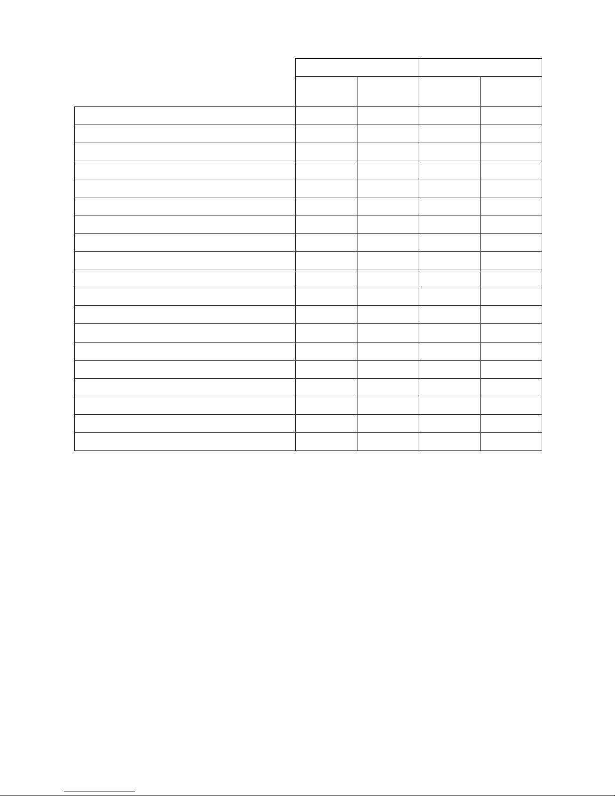
Micromite Family Summary
Micromite Micromite Plus
28-pin
Dual In Line
44-pin
SMD
64-pin
SMD
100-pin
SMD
Maximum CPU Speed 48 MHz 48 MHz 120 MHz 120 MHz
Maximum BASIC Program Size 59 KB 59 KB 100 KB 100 KB
RAM Memory Size (used for variables, buffers, etc) 52 KB 52 KB 108 KB 108 KB
Clock Speed (MHz) 5 to 48 5 to 48 5 to 120 5 to 120
Serial Console for Programming and Control
USB Console (serial emulator over USB 2.0)
PS2 Keyboard and LCD Display Console
SD Card Interface (FAT16 or FAT32 up to 64GB)
Total Number of I/O pins 19 33 45 77
Number of Analog Inputs 10 13 28 28
Number of Serial I/O ports 2 2 3 or 4 3 or 4
Number of SPI Channels 1 1 2 2
Number of I2C Channels 1 1 1 + RTC 1 + RTC
Maximum Number of 1-Wire I/O pins 19 33 45 77
Number of PWM or Servo Channels 5 5 5 5
Supports 2.2", 2.4" and 2.8" SPI LCD Displays
Supports eleven LCD Displays from 1.4" to 8"
Supports Resistive Touch Panels
Power Requirements 3.3V 30 mA 3.3V 30 mA 3.3V 80 mA 3.3V 80 mA
Micromite Plus Manual Page 6
Suitable Microcontrollers
The microcontroller used in the Micromite Plus is available in two different frequency specifications (100MHz
and 120MHz). The Micromite Plus will start up at 100MHz and if you have a 120MHz chip you can use the
CPU command to step up to 120MHz. See http://microchip.com for the data sheets.
The recommended chips are:
PIC32MX470F512H-I/PT 64-pin TQFP package – maximum speed 100 MHz
PIC32MX470F512H-120/PT 64-pin TQFP package – maximum speed 120 MHz
PIC32MX470F512L-I/PF 100-pin TQFP package – maximum speed 100 MHz
PIC32MX470F512L-120/PF 100-pin TQFP package – maximum speed 120 MHz
All these chips are in a TQFP surface mount package with a lead pitch of 0.5 mm. They are reasonably easy to
solder and can be mounted on a carrier board (for example futurlec.com part code 64PINTQFP) or the
Explore64 which is a breadboard compatible PCB or the Explore100 which is designed to mate with a 5"
display (see http://geoffg.net/micromite.html for examples).
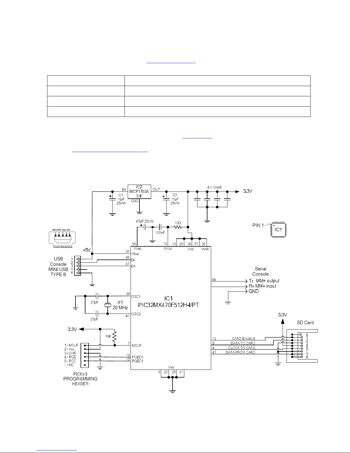
Typical Circuit
Note that the pin numbers refer to the 64-pin chip. For the 100-pin chip refer to the table in the next section.
Note that the only required components are:
The capacitor on pin 56 (Vcap). This must be a tantalum (47 µF) or multilayer ceramic (10 µF) type.
The 20 MHz crystal and its two 27pF load capacitors.
The 10 KΩ pullup resistor on pin 7 (MCLR).
Micromite Plus Manual Page 7
Micromite Plus Connections
The tick column ANA means ANALOG, DIG means digital I/O and 5V means a 5 V tolerant pin. Pins marked
SSD1963 xxx are required for a SSD1963 based display - see the "Micromite Advanced Features" manual for
more details. Otherwise the notation is similar as described for the 28-pin version.
64-pin Micromite Plus
A
N
A
D
I
G
5
V
5
V
D
I
G
A
N
A
DIGITAL INPUT ONLY 33
32 PWM 2B
USB +5V 34
31
POWER (+2.3 to +3.6V) 35
30
USB D- 36
29 COM1: ENABLE
USB D+ 37
28 SSD1963 RESET
POWER (+2.3 to +3.6V) 38
27 SSD1963 RS (data/command)
20MHz CRYSTAL) 39
26 POWER (+2.3 to +3.6V)
20MHz CRYSTAL) 40
25 GROUND
GROUND 41
24 SSD1963 WR
PWM 1B 42
23 COUNT
I2C DATA 43
22
I2C CLOCK 44
21
SPI 1 IN (MISO) 45
20 ANALOG GROUND
46
19 ANALOG POWER (+2.3 to +3.6V)
SPI 2 IN (MISO) 47
18
PWM 1A 48
17 COM3: Rx
COUNT 49
16 COM3: Tx
SPI 1 CLOCK 50
15 COM1: Tx
COUNT | WAKEUP | IR 51
14
COUNT 52
13 COM2: Rx
PWM 2A 53
12
KEYBOARD CLOCK 54
11 COM2: Tx
KEYBOARD DATA 55
10 POWER (+2.3 to +3.6V)
47µF TANT CAPACITOR (+) 56
9 GROUND
POWER (+2.3 to +3.6V) 57
8 SPI 1 OUT (MOSI)
COM4: Tx | CONSOLE Tx (OUT) 58
7 RESET Normally 10KΩ to V+
COM1: Rx 59
6 CONSOLE Rx (IN) | COM4: Rx
SSD1963 D0 60
5 SPI 2 OUT (MOSI) |
SSD1963 D1 61
4 SPI 2 CLOCK
SSD1963 D2 62
3 SSD1963 D7
PWM 1C | SSD1963 D3 63
2 SSD1963 D6
SSD1963 D4 64
1 SSD1963 D5

Micromite Plus Manual Page 8
100-pin Micromite Plus
A
N
A
D
I
G
5
V
5V D
I
G
A
N
A
DIGITAL INPUT ONLY
51
F3 F5
50
52
F2 F4
49 53
F8 D15
48 USB +5V
54
D14
47 POWER (+2.3 to +3.6V)
55 46 POWER (+2.3 to +
3.6V)
USB D
- 56
45 GROUND
USB D+
57
B15
44 58
A2 B14
43 COM1: ENABLE
59
A3 B13
42 SSD1963 RESET
60
A4 B12
41 61
A5 F12
40 POWER (+2.3 to +3.6V)
62
F13
39 20MHz CRYSTAL
) 63 A1
38 20MHz CRYSTAL
) 64
37 POWER (+2.3 to +3.6V)
GROUND
65 36 GROUND
I2C CLOCK
66
A14 B11
35
I2C DATA
67
A15 B10
34 COUNT
PWM 1B
68
D8
33 69
D9 B8
32
SPI 1 CLOCK
70
D10 31 ANALOG
GROUND
SPI 1 IN (MISO)
71
D11 30
ANALOG
POWER (+2.3 to +3.6V)
SPI 1 OUT (MOSI)
72
D0 A10
29 73
C13 A9
28 PWM 1A
74
C14 B7
27
GROUND
75 B6
26 COM3: Rx
COUNT
76
D1 B0
25 COM3
: Tx
77
D2 B1
24 COM1: Tx
COUNT | WAKEUP | IR
78
D3 B2
23
PWM 1C
79
D12 B3
22 COM2: Rx
80
D13 B4
21
COUNT
81
D4 B5
20 COM2: Tx
PWM 2A
82
D5 E9
19 SSD1963
WR KEYBOARD CLOCK
83
D6
E8
18 SSD1963 RS (data/command)
KEYBOARD DATA
84
D7 A0
17
47µF TANT CAPACITOR (+)
85 16 POWER (+2.3 to +3.6V)
POWER (+2.3 to +3.6V)
86 15 GROUND
COM4: Tx |
CONSOLE Tx (OUT)
87
F0 G9
14
COM1: Rx
88
F1
13 RESET
Normally
10K
Ω to V+
COM4: Rx | CONSOLE Rx (IN
) 89
G1 G8
12 SPI 2 OUT (MOSI)
90
G0 G7
11 SPI 2 IN (MISO)
91
A6 G6
10 SPI 2 CLOCK
92
A7 C4
9 PWM 2B
SSD1963 D0
93
E0
8
SSD1963 D1
94
E1 C2
7 95
G14 C1
6 96
G12 E7
5 SSD1963 D7
97
G13 E6
4 SSD1963 D6
SSD1963 D2
98
E2 E5
3 SSD1963 D5
SSD1963 D3
99
E3 2
POWER (+2.3 to +3.6V)
SSD1963 D4
100
E4
G15
1
Micromite Plus Manual Page 9
Programming the Firmware
Programming the 64 and 100-pin Micromite Plus is similar to programming the 28-pin standard Micromite
described in the Micromite User Manual.
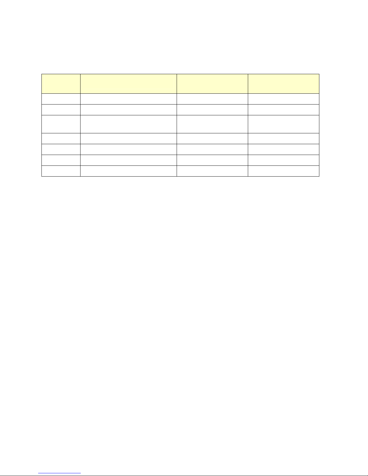
Refer to the following table for the pin connections to a PICkit 3 programmer:
PICkit 3
Pins
Description
64-pin Micromite Plus
Pin Numbers
100-pin Micromite Plus
Pin Numbers
47µF Tantalum Capacitor to GND 56 85
1 - MCLR Master Reset (active low) 7 13
2 - Vcc Power Supply (3.3V) 10, 19, 26, 35, 38, and 57
2, 16, 30, 37, 46, 55, 62
and 86
3 - GND Ground 9, 20, 25 and 41 15, 31, 36, 45, 65 and 75
4- PGD Programming Data 16 25
5 - PGC Programming Clock 15 24
6 - NC Not used
Notes:
A pullup resistor of 10 K is required between the MCLR pin and Vcc.
A crystal is not required to program these chips and will be ignored if it is present.
The microcontroller being programmed can be powered by the PICkit 3 but it is recommended that a
separate power supply be used. When the PICkit 3 supplies the power pin 2 (Vcc) on the PICkit 3 will
become an output supplying the power to the chip being programmed.

Micromite Plus Manual Page 10
SPI Based LCD Displays
The Micromite Plus includes support for three types of colour LCD display panels using a SPI interface. These
are the:
Standard 2.2”, 2.4" and 2.8” 240x320 pixel display with an ILI9341 controller as described in the
Micromite User Manual.
A 1.8" 128 x160 pixel display with a ST7735 controller
A 1.44" 128 x128 pixel display using the ILI9163 controller.
On eBay you can find suitable displays by searching for the controller name (ILI9341, ST7735 or ILI9163).
ILI9341 Based Displays
The ILI9341 based displays are illustrated on the right.
They use an SPI interface and have the following basic
specifications:
A 2.2, 2.4 or 2.8 inch display
Resolution of 240 x 320 pixels and a colour depth of
262K/65K
A ILI9341 controller with a SPI serial interface
ST7735 Based Displays
The ST7735 based displays also use a SPI interface and are smaller than the
ILI9341 based displays. ST7735 displays have the following basic
specifications:
A 1.8 inch display
Resolution of 128 x 160 pixels and a colour depth of 262K/65K
A ST7735 controller with a SPI serial interface
These do not come with a touch controller.
A typical ST7735 based display is illustrated on the right. On eBay
you can find suitable displays by searching for the controller name
(ST7735).
ILI9163 Based Displays
ILI9163 based displays have a 1.44 inch display with 128x128 pixels. They
have an SPI interface and use the same connections as ST7735 based displays.
ILI9163 based displays use an SPI interface and have the following basic
specifications:
A 1.44 inch display
Resolution of 128 x 128 pixels
A ILI9163 controller with a SPI serial interface
A typical ILI9163 based display is illustrated on the right. On eBay you can
find suitable displays by searching for the controller name (ILI9163).
Be warned, apparently some displays with a red PCB have a fault and will not
work with the Micromite Plus. So, you should choose a display with a black
PCB (as illustrated) as these have been tested and work correctly

Micromite Plus Manual Page 11
Connecting SPI Based LCD Panels
The SPI based display controllers share the second SPI channel (SPI2) interface on the Micromite Plus with the
touch controller (if present) and the SD Card interface if implemented. If any of these features are enabled SPI2
will also be unavailable to BASIC programs (which can use the first SPI channel instead).
The following table lists the connections required between the ILI9341, ST7735 and ILI9163 based LCD display
board and the Micromite Plus:
ILI9341
Display
ST7735 or
ILI9163
Display
Description
Micromite Plus
64-pin
version
Micromite Plus
100-pin
version
T_IRQ Touch Interrupt Configurable (see Touch Support)
T_DO Touch Data Out (MISO)
Pin 47
Pin 11
T_DIN Touch Data In (MOSI)
Pin 5
Pin 12
T_CS Touch Chip Select Configurable (see Touch Support)
T_CLK Touch SPI Clock
Pin 4
Pin 10
SDO (MISO) Display Data Out (MISO)
Pin 47
Pin 11
LED LED Power supply for the backlight (see below)
SCK SCK Display SPI Clock
Pin 4
Pin 10
SDI (MOSI) SDA Display Data In (MOSI)
Pin 5
Pin 12
D/C A0 Display Data/Command Control Configurable
RESET RESET Display Reset (when pulled low) Configurable
CS CS Display Chip Select Optional - Configurable
GND GND Ground
VCC VCC 5V supply (the controller draws less than 10mA)
Where a Micromite Plus connection is listed as "configurable" the specific pin should be specified with the
OPTION LCDPANEL or OPTION TOUCH commands (see below).
The backlight power (the LED connection) should be supplied from the main 5V supply via a current limiting
resistor. A typical value for this resistor on the ILI9341 based LCD display is 18Ω for a current of about 63mA
and on the ST7735 or ILI9163 display is 39Ω for a current of about 30mA. The value of this resistor can be
varied to reduce the power consumption or to provide a brighter display.
Important: Care must be taken with display panels that share the SPI port between a number of devices (display
controller, touch, etc). In this case all the Chip Select signals must be configured in MMBasic or disabled by a
permanent connection to 3.3V. If this is not done any unconnected Chip Select pins will float causing the wrong
controller to respond to commands on the SPI bus.
Configuring an SPI Based LCD Panel
To use the display MMBasic must be configured using the OPTION LCDPANEL command which must be
entered at the command prompt (not in a program).
The syntax is:
OPTION LCDPANEL controller, orientation, D/C pin, reset pin [,CS pin]
Where:
'controller' can be either ILI9341, ST7735 or ILI9163.
'orientation' can be LANDSCAPE, PORTRAIT, RLANDSCAPE or RPORTRAIT. These can be abbreviated to
L, P, RL or RP. The R prefix indicates the reverse or "upside down" orientation.
'C/D pin' and 'reset pin' are the Micromite I/O pins to be used for these functions. Any free pin can be used.

Micromite Plus Manual Page 12
'CS pin' can also be any I/O pin but is optional. If a touch controller is not used this parameter can be left off the
command and the CS pin on the LCD display wired permanently to ground. If the touch controller is used this pin
must then be specified and connected to a Micromite I/O pin.
To test the display you can enter the command GUI TEST LCDPANEL. You should see an animated display of
colour circles being rapidly drawn on top of each other. Press the space bar on the console’s keyboard to stop the
test.
Important: The above test may not work if the display has a touch controller and the touch controller has not been
configured (ie, the touch Chip Select pin is floating). In this case configure the touch controller (see below) and
then retry GUI TEST LCDPANEL.
To verify the configuration you can use the command OPTION LIST to list all options that have been set
including the configuration of the LCD panel.
Examples
For the 64-pin Micromite Plus the following allocations are recommended:
Pin 44 for the display Chip Select
Pin 43 for the display Data/Command control
Pin 42 for the display reset control
Pin 45 for the touch Chip Select
Pin 46 for the touch IRQ input
Pin 52 is the SD card Chip Select
The corresponding configuration commands are:
OPTION LCDPANEL ILI9341, L, 44, 43, 42
OPTION TOUCH 45, 46
OPTION SDCARD 52
These match the pin allocations on the TFT Backpack+ PCB board offered by CircuitGizmos. See:
http://circuitgizmos.com/gizmo-store/#!/TFT-Backpack+-PCB-Peter-Mather/p/65473479

Micromite Plus Manual Page 13
SSD1963 Based LCD Displays
In addition to the SPI based controllers the Micromite Plus also supports colour LCD displays using the SSD1963
controller. These use a parallel interface, are available in sizes from 4.3" to 8" and have better specifications than
the smaller displays. Typically they cost about US$30 for the 4.3" version to US$50 for the 7" version. All these
displays have an SD card socket which is fully supported by MMBasic on the Micromite Plus.
On eBay you can find suitable displays by searching for the controller name (SSD1963).
Because the SSD1963 controller uses a parallel interface the Micromite Plus can transfer data much faster than an
SPI interface resulting in a very quick screen update. These displays are also much larger, have more pixels and
are brighter. MMBasic drives them using 24-bit true colour for a full colour rendition (16 million colours).
The characteristics of these displays are:
A 4.3, 5, 7 or 8 inch display
Resolution of 480 x 272 pixels (4.3" version) or 800 x 480 pixels (5”, 7" or 8" versions).
A SSD1963 display controller with a parallel interface (8080 format).
A touch controller (SPI interface).
A full sized SD card socket.
There are a number of different designs
using the SSD1963 controller but
fortunately most Chinese suppliers have
standardised on a single connector as
illustrated below. It is strongly
recommended that any display purchased
has a matching connector – this provides
some confidence that the manufacturer
has followed the standard that the
Micromite Plus is designed to use.

Micromite Plus Manual Page 14
Connecting an SSD1963 Based LCD Panel
The SSD1963 controller uses a parallel interface while the touch controller and SD card use an SPI interface. The
touch and SD card features are optional but if they are used they will use the second SPI port (SPI2).
The following table lists the connections required between the display board and the Micromite Plus to support
the SSD1963 interface and the LCD display. The touch controller and SD card interfaces are listed further below.
SSD1963
Display
Description
64-pin
Micromite+
100-pin
Micromite+
DB0 Parallel Data Bus bit 0 Pin 60 Pin 93
DB1 Parallel Data Bus bit 1 Pin 61 Pin 94
DB2 Parallel Data Bus bit 2 Pin 62 Pin 98
DB3 Parallel Data Bus bit 3 Pin 63 Pin 99
DB4 Parallel Data Bus bit 4 Pin 64 Pin 100
DB5 Parallel Data Bus bit 5 Pin 1 Pin 3
DB6 Parallel Data Bus bit 6 Pin 2 Pin 4
DB7 Parallel Data Bus bit 7 Pin 3 Pin 5
CS Chip Select (active low) Ground (ie, always selected)
WR Write (active low) Pin 24 Pin 19
RD Read (active low) Configurable
RS Command/Data Pin 27 Pin 18
RESET Reset the SSD1963 Pin 28 Pin 42
LED_A Backlight control for an unmodified display panel Configurable
5V 5V power for the backlight on some displays (most displays use the 3.3V supply for this).
3.3V Power supply.
GND Ground
The following table lists the connections required to support the touch controller interface:
SSD1963
Display
Description
64-pin
Micromite+
100-pin
Micromite+
T_CS Touch Chip Select Configurable
T_IRQ Touch Interrupt Configurable
T_DIN Touch Data In (MOSI) Pin 5 Pin 12
T_CLK Touch SPI Clock Pin 4 Pin 10
T_DO Touch Data Out (MISO) Pin 47 Pin 11
The following table lists the connections required to support the SD card connector:
SSD1963
Display
Description
64-pin
Micromite+
100-pin
Micromite+
SD_CS SD Card Chip Select Configurable
SD_DIN SD Card Data In (MOSI) Pin 5 Pin 12
SD_CLK SD Card SPI Clock Pin 4 Pin 10
SD_DO SD Card Data Out (MISO) Pin 47 Pin 11
Micromite Plus Manual Page 15
Where a Micromite connection is listed as "configurable" the specific pin should be specified in the appropriate
OPTION command (see below).
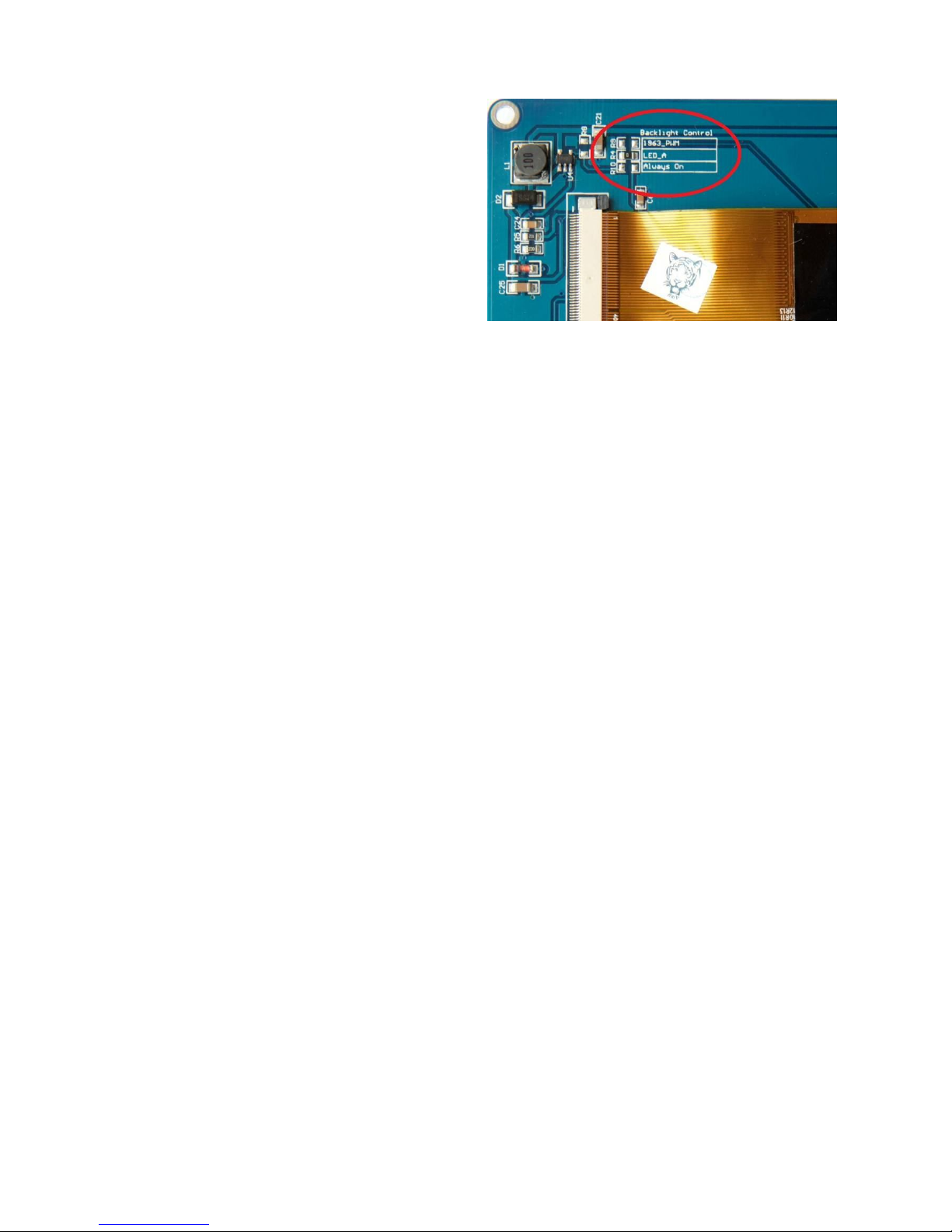
Most SSD1963 based LCD panels have three pairs of
solder pads on the PCB which are grouped under the
heading "Backlight Control" as illustrated on the right.
Normally the pair marked "LED-A" are shorted together
with a zero ohm resistor and this allows control of the
backlight's brightness with a PWM (pulse width
modulated) signal on the LED-A pin of the display
panel's main connector.
The Micromite Plus fully supports this form of control
and if you do not want to be bothered with the details
you can specify the I/O pin used to drive the LED-A pin
in the OPTION LCDPANEL command (below).
However, it is better to use the SSD1963 controller to generate this signal as it frees up one I/O pin and it allows
the brightness to be controlled with a finer degree of resolution (1% instead of 5% steps). To use the SSD1963 for
brightness control the zero ohm resistor should be removed from the pair marked "LED-A" and used to short the
nearby pair of solder pads marked "1963-PWM". The Micromite Plus can then control the brightness via the
SSD1963 controller.
In either case the BACKLIGHT command will work the same and can be used to dynamically change the
display's brightness.
Generally 7 inch and larger displays have a separate pin on the connector (marked 5V) for powering the backlight
from a 5V supply. If this pin is not provided the backlight power will be drawn from the 3.3V pin. Note that the
power drawn by the backlight can be considerable. For example, a 7 inch display will typically draw 330 mA
from the 5V pin.
Care must be taken with display panels that share the SPI port between a number of devices (SD card, touch, etc).
In this case all the Chip Select signals must configured in MMBasic or disabled by a permanent connection to
3.3V. If this is not done the pin will float causing the wrong controller to respond to commands on the SPI bus.
On the Micromite Plus the second SPI channel (SPI2) is used to communicate with the touch controller and the
SD Card interface. If any of these features are enabled SPI2 will be unavailable to BASIC programs (which can
use the first SPI channel instead).
Configuring an SSD1963 Based LCD Panel
To use the display MMBasic must be configured using the OPTION LCDPANEL command which must be
entered at the command prompt (not in a program).
The syntax is:
OPTION LCDPANEL controller, orientation [,LCD-A pin] [,RD pin]
Where:
'controller' can be either:
SSD1963_4 For a 4.3 inch display
SSD1963_5 For a 5 inch display
SSD1963_5A For an alternative version of the 5 inch display if SSD1963_5 does not work
SSD1963_7 For a 7 inch display
SSD1963_7A For an alternative version of the 7 inch display if SSD1963_7 does not work.
SSD1963_8 For an 8 inch display.
'orientation' can be LANDSCAPE, PORTRAIT, RLANDSCAPE or RPORTRAIT. These can be abbreviated to
L, P, RL or RP. The R prefix indicates the reverse or "upside down" orientation.
'LCD-A pin' can also be any I/O pin but is optional. This can be used to control the brightness of the backlight if
the internal SSD1963 controller is not used (see the notes above).
'RD pin' can also be any I/O pin and is connected to the RD (read) pin of the LCD display panel. This is optional
and if specified will allow the use of transparent text and the BLIT command (transparent text is displayed when
the background colour is specified as -1).

Micromite Plus Manual Page 16
This command only needs to be run once. From then on MMBasic will automatically initialise the display on
startup or reset. In some circumstances it may be necessary to interrupt power to the LCD panel while the
Micromite is running (eg, to save battery power) and in that case the GUI RESET LCDPANEL command can
be used to reinitialise the display.
If the LCD panel is no longer required the command OPTION LCDPANEL DISABLE can be used which will
return the I/O pins for general use.
To verify the configuration you can use the command OPTION LIST to list all options that have been set
including the configuration of the LCD panel.
To test the display you can enter the command GUI TEST LCDPANEL. You should see an animated display of
colour circles being rapidly drawn on top of each other. Press the space bar on the console’s keyboard to stop the
test.
100-Pin Example
The Explore 100 board with the 100-pin Micromite Plus uses the following pin allocations:
Pin 48 is the SSD1966 LED_A control
Pin 6 is the SSD1963 RD pin
Pin 1 is the touch Chip Select
Pin 40 is the touch IRQ input
Pin 39 is the touch click output (see the next chapter)
Pin 47 is the SD card Chip Select
The corresponding configuration commands are:
OPTION LCDPANEL SSD1963_5, LANDSCAPE, 48, 6
OPTION TOUCH 1, 40, 39
OPTION SDCARD 47
Because the RD pin is specified for the SSD1963 display programs will be able to display transparent text and use
the BLIT command.
64-Pin Example
For the Explore 64 board (64-pin Micromite Plus) the following allocations are recommended:
Pin 12 for the SSD1966 LED_A control
Pin 51 for the touch Chip Select
Pin 33 for the touch IRQ input
Pin 50 for the touch click output (see the next chapter)
Pin 52 is the SD card Chip Select
The corresponding configuration commands are:
OPTION LCDPANEL SSD1963_5, LANDSCAPE, 12
OPTION TOUCH 51, 33, 50
OPTION SDCARD 52
These match the pin allocations on the TFT Backpack+ PCB board offered by CircuitGizmos. See:
http://circuitgizmos.com/gizmo-store/#!/TFT-Backpack+-PCB-Peter-Mather/p/65473479
Because the RD pin is not specified programs will not be able to use transparent text and the BLIT command.

Micromite Plus Manual Page 17
Touch Support
The Micromite User Manual describes how to setup and calibrate a resistive touch sensitive panel. This section
concentrates on the additional features offered by the Micromite Plus.
Configuring Touch
To configure the Micromite Plus for a touch panel the OPTION TOUCH command is used:
OPTION TOUCH T_CS pin, T_IRQ pin [, click pin]
Where:
'T_CS pin' and 'T_IRQ pin' are the Micromite I/O pins to be used for chip select and touch interrupt respectively
(any free pins can be used).
'click pin' is exclusive to the Micromite Plus and specifies an I/O pin that will be driven briefly high when a
screen control is touched. This can be used to drive a small Piezo buzzer which will produce a click sound
providing an audible feedback when a GUI element on the screen is activated (see the section "Graphical User
Interface Commands").
A typical buzzer that can be used is Altronics Part Number S6108 or S6104
Note that most I/O pins on the Micromite Plus are capable of driving 15mA (pins 50, 44 and 6 on the 64-pin
chip can drive 30mA). However many buzzers require more that this so a transistor might be necessary to
buffer the Micromite Plus output and drive the buzzer.
This command only needs to be run once as the parameters are stored in non volatile memory.
Calibrating the Touch Screen
Calibrating the touch screen is done using the GUI CALIBRATE command. When run this command will
present a series of four targets on the screen that must be touched.
This process is fully described in the Micromite User Manual.
Touch Functions
To detect if and where the screen is touched you can use the following functions in a BASIC program.
Note that the first two functions are common across all versions of the Micromite, the remainder are unique to
the Micromite Plus.
TOUCH(X)
Returns the X coordinate of the currently touched location or -1 if the screen is not being touched.
TOUCH(Y)
Returns the Y coordinate of the currently touched location or -1 if the screen is not being touched.
TOUCH(DOWN)
Returns true if the screen is currently being touched (this is much faster than TOUCH(X or Y)).
TOUCH(UP)
Returns true if the screen is currently NOT being touched (also faster than TOUCH(X or Y))
TOUCH(LASTX)
Returns the X coordinate of the last location that was touched.
TOUCH(LASTY)
Returns the Y coordinate of the last location that was touched.
TOUCH(REF)
Returns the reference number of the control that is currently being touched or zero if no control is being
touched. See the section Advanced Graphics for more details.
TOUCH(LASTREF)
Returns the reference number of the control that was last touched.

Micromite Plus Manual Page 18
The GUI BEEP Command
The Piezo buzzer specified in the OPTION TOUCH command can also be driven by a BASIC program using
the command:
GUI BEEP msec
Where 'msec' is the number of milliseconds that the beeper should be driven. A time of 3ms produces a click
while 100ms produces a short beep.
Touch Interrupts
On the Micromite Plus the GUI INTERRUPT command is used to setup a touch interrupt. The syntax is:
GUI INTERRUPT down [, up]
Where 'down' is the subroutine to call when a touch down has been detected. And optionally 'up' is the
subroutine to call when the touch has been lifted from the screen ('up' and 'down' can point to the same
subroutine if required).
As an example, the following program will print out the X and Y coordinates of any touch on the screen:
GUI INTERRUPT MyInt
DO : LOOP
SUB MyInt
PRINT TOUCH(X) TOUCH(Y)
END SUB
Specifying the number zero (single digit) as the argument will cancel both up and down interrupts. ie:
GUI INTERRUPT 0
Micromite Plus Manual Page 19
SD Card Support
The Micromite Plus has full support for SD cards. This includes opening files for reading, writing or random
access and loading and saving programs.
The firmware will work with cards up to 64 GB formatted in FAT16 or FAT32 and the files created can also be
read/written on personal computers running Windows, Linux or the Mac operating system.
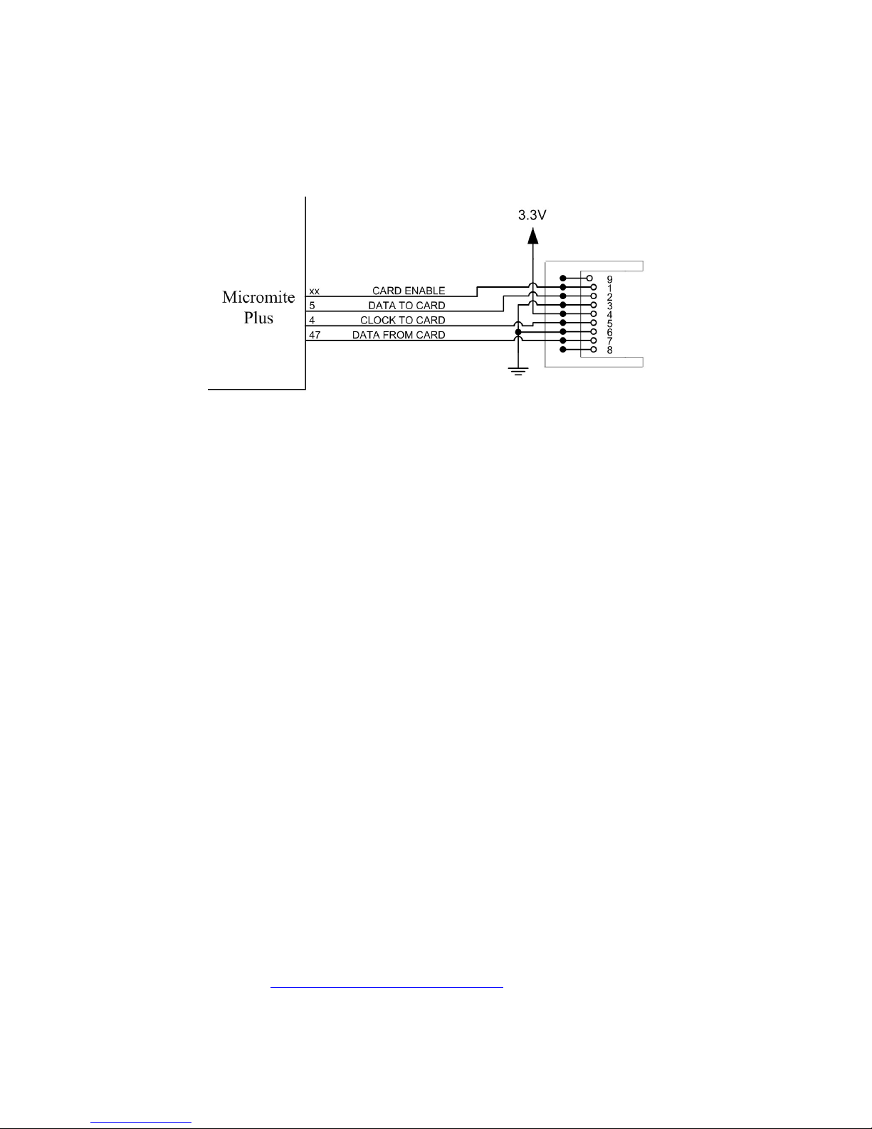
The basic circuit diagram for connecting the SD card connector to the 64-pin Micromite Plus is illustrated
below. Note that the pin number used for Card Enable is selected when configuring the interface.
Care must be taken with display panels that share the SPI port between a number of devices (SD card, touch, etc).
In this case all the Chip Select signals must configured in MMBasic or alternatively disabled by a permanent
connection to 3.3V. If this is not done any floating Chip Select signal lines will cause the wrong controller to
respond to commands on the SPI bus.
Configuring the SD Card
To use the SD card MMBasic must be configured using the OPTION SDCARD command which must be entered
at the command prompt (not in a program).
The syntax is:
OPTION SDCARD CS-pin [, CD-pin [,WP pin]]
Where:
'CS-pin' is the I/O pin number that will be used as chip select (pin 1 on the SD card connector).
'CD-pin' is optional and is the I/O pin number that will be used to connect to the card detect pin on the SD card
connector. The Micromite will provide a weak pullup on this pin which is normally pulled high but, when a card
is inserted, it will be connected to ground and the signal line pulled low. On some connectors this signal is not
provided and in that case the Micromite Plus would need to be restarted if the SD card was changed.
'WP-pin' is optional and is the I/O pin number that will be used to connect to the write protect pin on the SD card
connector. The Micromite will provide a weak pullup on this pin which is normally pulled high but, when a card
is write protected, it will be connected to ground and the signal line pulled low.
The state of the 'CD-pin' and 'WP-pin' can also be read using the PIN() function which is useful for checking the
status of an SD card before opening it..
Some SD card connectors reverse the polarity of the 'CD-pin' or 'WP-pin' signal - ie, they are open (and therefore
the signal is high) when the card is inserted or write protected. In this case the pin numbers used for 'CD-pin' and
'WP-pin' can be a negative number. This will tell MMBasic to invert the polarity of these signals.
This command only needs to be run once. When the Micromite is restarted MMBasic will automatically initialise
the SD card interface. If the SD card is no longer required the command OPTION SDCARD DISABLE can be
used which will disable the SD card and return the I/O pins for general use.
To verify the configuration you can use the command OPTION LIST to list all options that have been set
including the configuration of the SD Card.
Specific Examples
On the Explore 64 module (http://www.rictech.nz/pages/5/Products) the SD Card Chip Select (CS) signal is on
pin 12 and the Card Detect (CD) signal is on pin 14. So, to enable the SD Card on this module the command is:
OPTION SDCARD 12, 14

Micromite Plus Manual Page 20
On the CGMICROBOARD2 module (www.circuitgizmos.com/products/cgmicroboard2/cgmicroboard2.shtml)
the SD Card Chip Select (CS) signal is on pin 49 and pin 30 is used for Card Detect). So, to enable the SD
Card on this module the command is: OPTION SDCARD 49, 30
The SnadPIC 100-pin PIC32 Module is useful if you are experimenting with the 100-pin Micromite Plus:
http://www.microcontroller-board.com/snadpic-board-32/14-snadpic-pic32mx470f512l-developmentboard.html#/crystal_oscillator-20mhz/crystal_rtcc-no_without_crystal_r
This is the company's standard PIC32 experimental board modified to suit the Micromite Plus firmware (it has
a 20M Hz crystal and does not include a RTC crystal). If you are purchasing this board make sure that you
specify these two details and the words "For Micromite" in the comments field.
On this module the SD Card Chip Select (CS) signal is on pin 14 and the Card Detect (CD) signal is on pin 18.
So, to enable the SD Card on this module the command is: OPTION SDCARD 14, 18
Note that on the 100-pin Micromite Plus pin 18 is used for driving a SSD1963 based LCD panel and will
conflict with its allocation as Card Detect. In this case the zero ohm resistor J3 on the underside of the
SnadPIC board must be removed so that SD Card Detect is no longer on pin 18. Another pin may be selected
via the CD pin on the top of the board.
MMBasic Support
MMBasic on the Micromite Plus supports the standard BASIC commands for working with storage systems.
Note that:
Long file/directory names are supported in addition to the old 8.3 format.
The maximum file/path length is 127 characters.
Upper/lowercase characters and spaces are allowed although the file system is not case sensitive.
Directory paths are allowed in file/directory strings. (ie, OPEN "\dir1\dir2\file.txt" FOR …).
Either forward or back slashes can be used in paths. Eg \dir\file.txt is the same as /dir/file.txt.
The current Micromite time is used for file create and last access times.
Up to ten files can be simultaneously open.
The CPU speed must be 30MHz or higher.
In the following commands/functions the # in #fnbr is optional and may be omitted.
OPEN fname$ FOR mode AS #fnbr
Opens a file for reading or writing. 'fname$' is the file name in 8.3 format. 'mode' can be INPUT,
OUTPUT, APPEND or RANDOM. ‘#fnbr’ is the file number (1 to 10).
PRINT #fnbr, expression [[,; ]expression] … etc
Outputs text to the file opened as #fnbr.
INPUT #fnbr, list of variables
Read a list of comma separated data into the variables specified from the file previously opened as #fnbr.
LINE INPUT #fnbr, variable$
Read a complete line into the string variable specified from the file previously opened as #fnbr.
CLOSE #fnbr [,#fnbr] …
Close the file(s) previously opened with the file number ‘#fnbr’.
Programs can be loaded from or saved to the SD card using two commands.
LOAD fname$ [, R]
Load a BASIC program from the SD Card. The optional suffix ",R" will cause the program to be run after
it has been loaded.
SAVE fname$
Save the current program to the SD card.
Images can be loaded from or saved to the SD card using two commands.
LOAD IMAGE fname$
Load a BMP file and display it on the LCD screen.

Micromite Plus Manual Page 21
SAVE IMAGE fname$
Save the current LCD screen image as a BMP file.
Basic file and directory manipulation can be done from within a BASIC program.
FILES [wildcard]
Search the current directory and list the files/directories found.
KILL fname$
Delete a file in the current directory.
MKDIR dname$
Make a sub directory in the current directory.
CHDIR dname$
Change into to the directory $dname. $dname can also be ".." (dot dot) for up one directory or "\" for the
root directory.
RMDIR dir$
Remove, or delete, the directory ‘dir$’ on the SD card.
SEEK #fnbr, pos
Will position the read/write pointer in a file that has been opened for RANDOM access to the 'pos' byte.
Also there are a number of functions that support the above commands.
INPUT$(nbr, #fnbr)
Will return a string composed of ‘nbr’ characters read from a file previously opened for INPUT with the
file number ‘#fnbr’. If less than ‘nbr’ characters are available the function will return with what it has
(including an empty string if no characters are available).
DIR$( fspec, type )
Will search an SD card for files and return the names of entries found.
EOF( #fnbr )
Will return true if the file previously opened for INPUT with the file number ‘#fnbr’ is positioned at the
end of the file.
LOC( #fnbr )
For a file opened as RANDOM this will return the current position of the read/write pointer in the file.
LOF( #fnbr )
Will return the current length of the file in bytes.
XModem Transfer
In addition to the standard method of XModem transfer which copies to or from the program memory the
Micromite Plus can also copy to and from a file on the SD card. The syntax is:
XMODEM SEND, filename$
or
XMODEM RECEIVE, filename$
Where ‘filename$’ is the file to save or send. In the case of receiving a file, any file on the SD card with the
same name will be automatically overwritten.
Load and Save Image
The LOAD IMAGE command can be used to load a bitmap image from the SD card and display it on the
attached LCD display panel. This can be used to draw a logo or add a background on the display. The syntax
of the command is:
LOAD IMAGE filename$ [, StartX, StartY]
Where ‘filename$’ is the image to load and ‘StartX’/’StartY’ are the coordinates of the top left corner of the
image (these default to the top left corner of the display if not specified). The image must be in BMP format

Micromite Plus Manual Page 22
and MMBasic will add “.BMP” to the file name if an extension is not specified. All types of the BMP format
are supported including black and white and true colour 24-bit images.
The LOAD IMAGE can display full colour, full screen images which look gorgeous. With high resolution
displays it will take some time to read the image from the SD Card (about 2 seconds for an 800x480 image).
The current image on the LCD screen can be saved to a file using the following command:
SAVE IMAGE filename$
This will save the image as a 24-bit true colour BMP file (the extension .BMP) will be added if an extension is
not supplied.
Example of Sequential I/O
In the example below a file is created and two lines are written to the file (using the PRINT command). The
file is then closed.
OPEN "fox.txt" FOR OUTPUT AS #1
PRINT #1, "The quick brown fox"
PRINT #1, "jumps over the lazy dog"
CLOSE #1
You can read the contents of the file using the LINE INPUT command. For example:
OPEN "fox.txt" FOR INPUT AS #1
LINE INPUT #1,a$
LINE INPUT #1,b$
CLOSE #1
LINE INPUT reads one line at a time so the variable a$ will contain the text "The quick brown fox" and b$
will contain "jumps over the lazy dog".
Another way of reading from a file is to use the INPUT$() function. This will read a specified number of
characters. For example:
OPEN "fox.txt" FOR INPUT AS #1
ta$ = INPUT$(12, #1)
tb$ = INPUT$(3, #1)
CLOSE #1
The first INPUT$() will read 12 characters and the second three characters. So the variable ta$ will contain
"The quick br" and the variable tb$ will contain "own".
Files normally contain just text and the print command will convert numbers to text. So in the following
example the first line will contain the line "123" and the second "56789".
nbr1 = 123 : nbr2 = 56789
OPEN "numbers.txt" FOR OUTPUT AS #1
PRINT #1, nbr1
PRINT #1, nbr2
CLOSE #1
Again you can read the contents of the file using the LINE INPUT command but then you would need to
convert the text to a number using VAL(). For example:
OPEN "numbers.txt" FOR OUTPUT AS #1
LINE INPUT #1, a$
LINE INPUT #1, b$
CLOSE #1
x = VAL(a$) : y = VAL(b$)
Following this the variable x would have the value 123 and y the value 56789.

Micromite Plus Manual Page 23
Random File I/O
For random access the file should be opened with the keyword RANDOM. For example:
OPEN "filename" FOR RANDOM AS #1
To seek to a record within the file you would use the SEEK command which will position the read/write
pointer to a specific byte. The first byte in a file is numbered one so, for example, the fifth record in a file that
uses 64 byte records would start at byte 257. In that case you would use the following to point to it:
SEEK #1, 257
When reading from a random access file the INPUT$() function should be used as this will read a fixed number
of bytes (ie, a complete record) from the file. For example, to read a record of 64 bytes you would use:
dat$ = INPUT$(64, #1)
When writing to the file a fixed record size should be used and this can be easily accomplished by adding
sufficient padding characters (normally spaces) to the data to be written. For example:
PRINT #1, dat$ + SPACE$(64 – LEN(dat$);
The SPACE$() function is used to add enough spaces to ensure that the data written is an exact length (64bytes
in this example). The semicolon at the end of the print command suppresses the addition of the carriage return
and line feed characters which would make the record longer than intended.
Two other functions can help when using random file access. The LOC() function will return the current byte
position of the read/write pointer and the LOF() function will return the total length of the file in bytes.
The following program demonstrates random file access. Using it you can append to the file (to add some data
in the first place) then read/write records using random record numbers. The first record in the file is record
number 1, the second is 2, etc.
RecLen = 64
OPEN "test.dat" FOR RANDOM AS #1
DO
abort: PRINT
PRINT "Number of records in the file =" LOF(#1)/RecLen
INPUT "Command (r = read,w = write, a = append, q = quit): ", cmd$
IF cmd$ = "q" THEN CLOSE #1 : END
IF cmd$ = "a" THEN
SEEK #1, LOF(#1) + 1
ELSE
INPUT "Record Number: ", nbr
IF nbr < 1 or nbr > LOF(#1)/RecLen THEN PRINT "Invalid record" : GOTO abort
SEEK #1, RecLen * (nbr - 1) + 1
ENDIF
IF cmd$ = "r" THEN
PRINT "The record = " INPUT$(RecLen, #1)
ELSE
LINE INPUT "Enter the data to be written: ", dat$
PRINT #1,dat$ + SPACE$(RecLen - LEN(dat$));
ENDIF
LOOP
Random access can also be used on a normal text file. For example, this will print out a file backwards:
OPEN "file.txt" FOR RANDOM AS #1
FOR i = LOF(#1) TO 1 STEP -1
SEEK #1, i
PRINT INPUT$(1, #1);
NEXT i
CLOSE #1
Micromite Plus Manual Page 24
Sound Output
The Micromite Plus can play stereo WAV files located on the SD card or generate precise sine waves using the
PLAY command.
The sound is played on the PWM 2 outputs as a stereo signal with the left channel on the PWM 2A pin and the
right on PWM 2B. The PWM and SERVO commands for controller 2 cannot be used while the sound is being
generated (however PWM/SERVO controller 1 is still available).
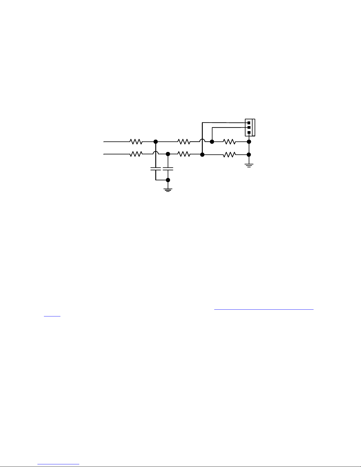
The audio signal is superimposed on an 80 KHz square wave as a pulse width modulated (PWM) signal. This
means that a low pass filter is required to recover the audio signal as shown below. This is a simple example
which relies on capacitor coupling into the following amplifier (most have this) and has an output level of about
1V peak to peak (650mV RMS).
1K 2.2K
PWM 2B
1K
2.2K
2.2K
2.2K
47nF47nF
PWM 2A
Micromite
Outputs
Stereo
Output
Left
Right
Common
This is suitable for general use, however more sophisticated designs can be implemented if required to improve
the frequency response and reject more of the carrier frequency. This circuit is also suitable for generating a
DC output signal using the PWM commands although in that case both the 47 nF capacitors should be increased
to 4.7 µF.
Playing WAV Files
The PLAY WAV command will play a WAV file residing on an SD card to the sound output. It can be used to
add sound effects to programs and provide informative announcements.
The syntax of the command is:
PLAY WAV file$ [, interrupt]
'file$' is the name of the WAV file to play. It must be on a connected SD card and the extension of .wav will be
appended if missing. The audio will play in the background (ie, the program will continue without pause).
'interrupt' is optional and is the name of a subroutine which will be called when the file has finished playing.
The WAV file must be PCM encoded in stereo with unsigned 8-bit sampling. The sample rate can be 8 KHz or
16 kHz. To convert a file to this format a program or website such as http://audio.online-convert.com/convert-
to-wav can be used (for this website set 8-bit resolution, set sampling rate to 8000 or 16000, set “Audio
Channels” to stereo. Click “Normalise audio”. Set PCM unsigned 8-bit in ADVANCED OPTIONS).
Generating Sine Waves
The PLAY TONE command also uses the sound output and will generate sine waves with selectable
frequencies for the left and right channels. This feature is intended for generating attention catching sounds
but, because the frequency is very accurate, it can be used for many other applications. For example, signalling
DTMF tones down a telephone line or testing the frequency response of loudspeakers.
The syntax of the command is:
PLAY TONE left [, right [, dur]]
'left' and 'right' are the frequencies in Hz to use for the left and right channels. The tone plays in the
background (the program will continue running after this command) and 'dur' specifies the number of
milliseconds that the tone will sound for.
If the duration is not specified the tone will continue until explicitly stopped or the program terminates. The
frequency can be from 1 Hz to 20 KHz and is very accurate (it is based on the Micromite's crystal oscillator).
The frequency can be changed at any time by issuing a new PLAY TONE command.

Micromite Plus Manual Page 25
Utility Commands
There are a number of commands that can be used to manage the sound output:
PLAY PAUSE Temporarily halt (pause) the currently playing file or tone.
PLAY RESUME Resume playing a file or tone that was previously paused.
PLAY STOP Terminate the playing of the file or tone. The sound output will also be
automatically stopped when the program ends.
PLAY VOLUME L, R Set the volume to between 0 and 100 with 100 being the maximum volume. The
volume will reset to the maximum level when a program is run.
PLAY CLOSE Turn off the PWM output.
In order to suppress the audible "pops" that can occur when the PWM output
waveform is turned on and off the PLAY command leaves the PWM signal
running even if it is paused and not being modulated. This normally will not affect
the normal running of the Micromite but if you want to turn it off (for example,
when entering sleep) you can use this command.

Micromite Plus Manual Page 26
Basic Drawing Features
The Micromite User Manual describes the basic drawing commands which are common across all versions of
the Micromite. This section concentrates on the additional features offered by the Micromite Plus.
All coordinates and measurements on the screen are done in terms of pixels with the X coordinate being the
horizontal position and Y the vertical position. The top left corner of the screen has the coordinates X=0 and
Y=0 and the values increase as you move down and to the right of the screen.
Read Only Variables
In the Micromite Plus there are six read only variables which provide useful information about the display
currently connected. The variables specific to the Micromite Plus are MM.HPOS and MM.VPOS, the others
are supported by all Micromites:
MM. HRES
Returns the width of the display (the X axis) in pixels.
MM. VRES
Returns the height of the display (the Y axis) in pixels.
MM.FONTHEIGHT
Returns the height of the current font (in pixels). All characters in a font have the same height.
MM.FONTWIDTH
Returns the width of a character in the current font (in pixels). All characters in a font have the same
width.
MM.HPOS
Returns the X coordinate of the text cursor (ie, the horizontal location (in pixels) of where the next
character will be printed on the LCD panel)
MM.VPOS
Returns the Y coordinate of the text cursor (ie, the vertical location (in pixels) of where the next
character will be printed on the LCD panel)
Colours
Colour is specified as a true colour 24 bit number where the top eight bits represent the intensity of the red
colour, the middle eight bits the green intensity and the bottom eight bits the blue.
MMBasic will automatically translate all colours to the format required by the individual display controller
which, in the case of the ILI9341, ST7735 and ILI9163 controllers, is 65K colours in the 565 format. In LCD
panels using the SSD1963 controller colours are displayed using the full 24-bit colour range (16 million colours).
Fonts
The Micromite Plus has six built in fonts plus it can use embedded fonts to a maximum of 16 fonts.
The built in fonts are:
Font
Number
Size
(width x height)
Character
Set
Description
1 8 x 13 All 95 characters A small font where a dense display is required.
2 12 x 20 All 95 characters General use on 480 x 272 displays
3 16 x 24 All 95 characters General use on 800 x 480 displays
4 16 x 24 BOLD All 95 characters A bold version of font #3
5 24 x 32 All 95 characters Large font, very clear
6 32 x 50 0 to 9 plus some symbols
Numbers plus decimal point, positive, negative,
equals, degree and colon symbols. Very clear.
In all fonts (including font #6) the back quote character (60 hex or 96 decimal) has been replaced with the
degree symbol (º).
Embedded Fonts
Both the standard Micromite and the Micromite Plus support embedded fonts. These are fully described in the
Micromite User Manual.

Micromite Plus Manual Page 27
Drawing Commands
Compared to the standard Micromite the Micromite Plus has one additional command:
TRIANGLE X1, Y1, X2, Y2, X3, Y3, C, FILL
Draws a triangle with the corners at X1, Y1 and X2, Y2 and X3, Y3. C is the colour of the triangle and
FILL is the fill colour. FILL can omitted or be -1 for no fill.
The other basic drawing commands are the same as in the standard Micromite. Refer to the Micromite User
Manual for a description of these.
Rotated Text
As described in the Micromite User Manual the justification of the text in the TEXT command can be specified
by using one or two characters in a string expression for the third parameter of the command. In the Micromite
Plus you can also specify a third character to indicate the rotation of the text. This character can be one of:
N for normal orientation
V for vertical text with each character under the previous running from top to bottom.
I the text will be inverted (ie, upside down)
U the text will be rotated counter clockwise by 90º
D the text will be rotated clockwise by 90º
This extra feature applies in the TEXT and GUI CAPTION commands.
As an example, the following will display the text "LCD Display" vertically down the left hand margin of the
display panel and centred vertically:
TEXT 0, 250, "LCD Display", "LMV", 5
Positioning is relative to the top left corner of the character when viewed normally so inverted 100,100 will
have the top left pixel of the first character at 100,100 and the text will then be above y=101 and to the left of
x=101. Similarly “R” in the justification string is viewed from the perspective of the character in whatever
orientation it is in (not the screen).
Transparent Text
If the display is capable of transparent text the TEXT command will allow the use of -1 for the background
colour. This means that the text is drawn over the background with the background image showing through the
gaps in the letters. Displays capable of transparent text are any that use the ILI9341 controller or an SSD1963
controller. The latter must have the RD pin specified in the OPTION LCDPANEL command. On the Micromite
eXtreme the VGA output also supports transparency (see the Micromite eXtreme Manual).
BLIT Command
If the display is capable of transparent text (see the above subheading) programs can also use the BLIT
command. This allows a portion of the image currently showing on the display to be copied to a memory
buffer and later copied back to the display. This is useful when something needs to be drawn over the
background and later removed without damaging the image in the background. Examples include a game
where a character is moving about in front of a landscape or the moving needle of a photorealistic gauge.
The available commands are:
BLIT READ #b, x, y, w, h
BLIT WRITE #b, x, y, w, h
BLIT CLOSE #b
#b is the buffer number in the range of 1 to 8. x and y are the coordinates of the top left corner and w and h are
the width and height of the image. READ will copy the display image to the buffer, WRITE will copy the
buffer to the display and CLOSE will free up the buffer and reclaim the memory used.
These commands can be used to copy a portion of the display to another location (by copying to a buffer then
writing somewhere else) but a simpler method is to use an alternative version of the BLIT command as follows:
BLIT x1, y1, x2, y2, w, h
This will copy a portion of the image at x1/y1 to the location x2/y2. w and h specify the width and height of
the image to be copied. The source and destination areas can overlap and the BLIT command will perform the
copy correctly.
This form of the BLIT command is particularly useful for creating graphs that can scroll horizontally or
vertically as new data is added.

Micromite Plus Manual Page 28
Backlight Control
The brightness of the backlight on a SSD1963 LCD panel can be controlled with the BACKLIGHT command:
BACKLIGHT percent
Where 'percent' is the degree of brightness ranging from 0 (fully off) to 100 (full brightness). This can be
changed as often as required and makes a huge difference to the power requirements of the display. For
example, a brightness of 50% will halve the current consumption (compared to 100%) while only making a
small difference to the perceived visual brightness.
Load Image
As previously described in the "SD Card Support" section the LOAD IMAGE command can be used to load a
bitmap image from the SD card and display it on the LCD display. This can be used to draw a logo or add an
ornate background to the graphics drawn on the display.

Micromite Plus Manual Page 29
Advanced Graphics
The Micromite Plus incorporates a suite of advanced graphic controls that respond to touch, these include on
screen switches, buttons, indicator lights, keyboard, etc. MMBasic will draw the control and animate it (ie, a
switch will depress when touched). All that the BASIC program needs to do is invoke a single line command
to specify the basic details of the control.
Each control has a reference number called '#ref' in the description of the control. By default this can be any
number between 1 and 100 and the upper limit can be changed with the OPTION CONTROL command. The
reference number is used to identify a control. For example, a check box can be created thus:
GUI CHECKBOX #10, "Test", 100, 100, 50, rgb(BLUE)
And the program can check its value by using its reference number in the CtrlVal() function:
IF CtrlVal(#10) THEN ...
The # character is optional but serves to remind the programmer that this is not an ordinary number.
In the following commands any arguments that are in italic font (eg, Width, Height) are optional and if not
specified will take the value of the previous command that did specify them. This means for example, that a
number of radio buttons with the same size and colour can be specified with only the first button having to list
all the details. Note that with the colour specification this is different to the Basic Drawing Commands which
default to the last COLOUR command.
All strings used in GUI controls and the MsgBox can display multiple lines by using the tilde character (~) to
separate each line in the string. For example, a push button's caption can be "ALARM~TEST" and this would
be displayed as two lines. For all controls the font used for the caption will be whatever is set with the FONT
command and the colours will be whatever was set by the last COLOUR command.
If the display is capable of transparent text these commands will allow the use of -1 for the background colour.
This means that the text is drawn over the background with the background image showing through the gaps in
the letters. Displays capable of transparent text are any that use the ILI9341 controller or an SSD1963
controller. The latter must have the RD pin specified in the OPTION LCDPANEL command. On the Micromite
eXtreme the VGA output also supports transparency (see the Micromite eXtreme Manual).
The advanced graphics controls are:
Frame
GUI FRAME #ref, caption$, StartX, StartY, Width, Height, Colour
This will draw a frame which is a box with round corners and a caption. A frame does not respond to touch but
is useful when a group of controls need to be visually brought together. It can also used to surround a group of
radio buttons and MMBasic will arrange for the radio buttons surrounded by the frame to be exclusive – that is,
when one radio button is selected any other button that was selected and within the frame will be automatically
deselected.
LED
GUI LED #ref, caption$, CenterX, CenterY, Diameter, Colour
This will draw an indicator light (it looks like a panel mounted LED). When its value is set to one it will be
illuminated and when it is set to zero it will be off (a dull version of its colour attribute). The LED can be made
to flash by setting its value to the number of milliseconds that it should remain on before turning off.
The caption will be drawn to the right of the LED and will use the colours set by the COLOUR command. A
LED does not respond to touch.
Check Box
GUI CHECKBOX #ref, caption$, StartX, StartY, Size, Colour
This will draw a check box which is a small box with a caption. Both the height and width are specified with
the 'Size' parameter. When touched an X will be drawn inside the box to indicate that this option has been
selected and the control's value will be set to 1. When touched a second time the check mark will be removed
and the control's value will be zero. The caption will be drawn to the right of the Check Box and will use the
colours set by the COLOUR command.

Micromite Plus Manual Page 30
Push Button
GUI BUTTON #ref, caption$, StartX, StartY, Width, Height, FColour, BColour
This will draw a momentary button which is a square switch with the caption on its face. When touched the
visual image of the button will appear to be depressed and the control's value will be 1. When the touch is
removed the value will revert to zero. Caption can be a single string with two captions separated by a vertical
bar (|) character (eg, "UP|DOWN"). When the button is up the first string will be used and when pressed the
second will be used.
Switch
GUI SWITCH #ref, caption$, StartX, StartY, Width, Height, FColour, BColour
This will draw a latching switch with the caption on its face. When touched the visual image of the button will
appear to be depressed and the control's value will be 1. When touched a second time the switch will be
released and the value will revert to zero. Caption can be a single string with two captions separated by a |
character (eg, "ON|OFF"). When this is used the switch will appear to be a toggle switch with each half of the
caption used to label each half of the toggle switch.
Radio Button
GUI RADIO #ref, caption$, CenterX, CenterY, Radius, Colour
This will draw a radio button with a caption. When touched the centre of the button will be illuminated to
indicate that this option has been selected and the control's value will be 1. When another radio button is
selected the mark on this button will be removed and its value will be zero. Radio buttons are grouped together
when surrounded by a frame and when one button in the group is selected all others in the group will be
deselected. If a frame is not used all buttons on the screen will be grouped together.
The caption will be drawn to the right of the button and will use the colours set by the COLOUR command.
Display Box
GUI DISPLAYBOX #ref, StartX, StartY, Width, Height, FColour, BColour
This will draw a box with rounded corners. Any text can be displayed in the box by using the CtrlVal(r) =
command. This is useful for displaying text, numbers and messages. This control does not respond to touch.
Text Box
GUI TEXTBOX #ref, StartX, StartY, Width, Height, FColour, BColour
This will draw a box with rounded corners. When the box is touched a QWERTY keyboard will appear on the
screen. Using this virtual keyboard any text can be entered into the box including upper/lower case letters,
numbers and any other characters in the ASCII character set. The new text will replace any text previously in
the box.
The value of the control can be set to a string starting with two hash characters (##) and in that case the string
(without the leading two hash characters) will be displayed in the box with reduced brightness. This can be
used to give the user a hint as to what should be entered (called "ghost text"). Reading the value of the control
displaying ghost text will return an empty string. When the control is used normally the ghost text will vanish.
MMBasic will try to position the virtual keyboard on the screen so as to not obscure the text box that caused it
to appear. A pen down interrupt will be generated when the keyboard is deployed and a key up interrupt will
be generated when the Enter or Cancel keys are touched and the keyboard is hidden. After most key presses
the subroutine MM.KEYPRESS will be called if it exists – – see the entry later in this chapter for a description
of how to use this facility.
If necessary the virtual keyboard can be dismissed by the program (same as touching the cancel button) with
the command: GUI TEXTBOX CANCEL. If the virtual keyboard is not displayed this will do nothing.
Number Box
GUI NUMBERBOX #ref, StartX, StartY, Width, Height, FColour, BColour
This will draw a box with rounded corners. When the box is touched a numeric keypad will appear on the
screen. Using this virtual keypad any number can be entered into the box including a floating point number in
exponential format. The new number will replace the number previously in the box.

Micromite Plus Manual Page 31
Similar to the Text Box, the value of the control can set to a literal string with two leading hash characters (eg,
"##Hint") and in that case the string (without the leading two characters) will be displayed in the box with reduced
brightness. Reading this will return zero and when the control is used normally the ghost text will vanish.
MMBasic will try to position the virtual keypad on the screen so as to not obscure the number box that caused
it to appear. A pen down interrupt will be generated when the keypad is deployed and a key up interrupt will
be generated when the Enter key is touched and the keypad is hidden. Also, when the Enter key is touched the
entered number will be evaluated as a number and the NUMBERBOX control redrawn to display this number.
After most key presses the subroutine MM.KEYPRESS will be called if it exists (see below).
If necessary the virtual keypad can be dismissed by the program (same as touching the cancel button) with the
command: GUI NUMBERBOX CANCEL. If it is not displayed this command will do nothing.
Spin Box
GUI SPINBOX #ref, StartX, StartY, Width, Height, FColour, BColour, Step,
Minimum, Maximum
This will draw a box with up/down icons on either end. When these icons are touched the number in the box
will be incremented or decremented by the 'StepValue', holding down the touch will repeat at a fast rate.
'Minimum' and 'Maximum' set a limit on the value that can be entered. 'StepValue', 'Minimum' and 'Maximum'
are optional and if not specified 'StepValue' will be 1 and there will be no limit on the number entered. A pen
down interrupt will be generated every time up/down is touched or when automatic repeat occurs.
Caption
GUI CAPTION #ref, text$, StartX, StartY, Justify, FColour, BColour
This will draw a text string on the screen. It is similar to the basic drawing command TEXT, the difference
being that MMBasic will automatically dim this control if a keyboard or number pad is displayed.
'Justify' is zero to three characters (a string expression or variable is also allowed) where the first letter is the
horizontal justification around X and can be L, C or R for LEFT, CENTER, RIGHT and the second letter is the
vertical placement around Y and can be T, M or B for TOP, MIDDLE, BOTTOM. A third character can be
used to indicate the rotation of the text. This can be 'N' for normal orientation, 'V' for vertical text with each
character under the previous running from top to bottom, 'I' the text will be inverted (ie, upside down), 'U' the
text will be rotated counter clockwise by 90º and 'D' the text will be rotated clockwise by 90º. The default
justification is left/top with no rotation.
If the colours are not specified this control will use the colours set by the COLOUR command.
Area
GUI AREA #ref, StartX, StartY, Width, Height
This will define an invisible area of the screen that is sensitive to touch and will generate touch down and touch
up interrupts. It can be used as the basis for creating a custom control which is defined and managed by the
BASIC program.
Interacting with Controls
Using the following commands and functions the characteristics of the on screen controls can be changed and
their value retrieved.
= CTRLVAL(#ref)
This is a function that will return the current value of a control. For controls like check boxes or switches it
will be the number one (true) indicating that the control has been selected by the user or zero (false) if not.
For controls that hold a number (eg, a SPINBOX) the value will be the number (normally a floating point
number). For controls that hold a string (eg, TEXTBOX) the value will be a string. For example:
PRINT "The number in the spin box is: " CTRLVAL(#10)
CTRLVAL(#ref) =
This command will set the value of a control. For off/on controls like check boxes it will override any
touch input and can be used to depress/release switches, tick/untick check boxes, etc. A value of zero is off
or unchecked and non zero will turn the control on. For a LED it will cause the LED to be illuminated or
turned off. It can also be used to set the initial value of spin boxes, text boxes, etc. For example:
CTRLVAL(#10) = 12.4

Micromite Plus Manual Page 32
GUI FCOLOUR colour, #ref1 [, #ref2, #ref3, etc]
This will change the foreground colour of the specified controls to 'colour'. This is especially handy for a
LED which can change colour.
GUI BCOLOUR colour, #ref1 [, #ref2, #ref3, etc]
This will change the background colour of the specified controls to 'colour'.
= TOUCH(REF)
This is a function that will return the reference number of the control currently being touched. If no control
is currently being touched it will return zero.
= TOUCH(LASTREF)
This is a function that will return the reference number of the control that was last touched.
GUI DISABLE #ref1 [, #ref2, #ref3, etc]
This will disable the controls in the list. Disabled controls do not respond to touch and will be displayed
dimmed. The keyword ALL can be used as the argument and that will disable all controls. For example:
GUI DISABLE ALL
GUI ENABLE #ref1 [, #ref2, #ref3, etc]
This will undo the effects of GUI DISABLE and restore the controls in the list to normal operation. The
keyword ALL can be used as the argument for all controls.
GUI HIDE #ref1 [, #ref2, #ref3, etc]
This will hide the controls in the list. Hidden controls will not respond to touch and will be replaced on the
screen with the current background colour. The keyword ALL can be used as the argument.
GUI SHOW #ref1 [, #ref2, #ref3, etc]
This will undo the effects of GUI HIDE and restore the controls in the list to being visible and capable of
normal operation. The keyword ALL can be used as the argument for all controls.
GUI DELETE #ref1 [, #ref2, #ref3, etc]
This will delete the controls in the list. This includes removing the image of the control from the screen
using the current background colour and freeing the memory used by the control. The keyword ALL can
be used as the argument and that will cause all controls to be deleted.
MM.KEYPRESS
If a subroutine with the name MM.KEYPRESS exists in the program it will be called by the NUMBERBOX
and TEXTBOX controls after each key on the virtual keypad is pressed. The control's reference number (an
integer) and the caption on the key (a string) are supplied as parameters and using these the subroutine can
inspect the current contents of the control and change it on the fly using CtrlVal(#ref). When the keypad is first
activated (by user's touch) this subroutine will also be called with reference number and the caption "Open".
For example. The following subroutine will force all text entered into a Text Box to uppercase:
SUB MM.KEYPRESS ref AS INTEGER, caption AS STRING
IF ref = MyTextBox THEN CtrlVal(ref) = UCase(CtrlVal(ref))
END SUB
Note that the subroutine checks the reference number supplied to determine which control is active. All
Number Box and Text Box controls will call this one subroutine so it therefore needs to check the reference
number to determine the correct action.
In the case of a Number Box the CtrlVal(#ref) function and command will act as a string inside the
MM.KEYPRESS function (normally the value of this control is a floating point number).
As an example of this behaviour, the following subroutine will ensure that the value returned by a Number Box
will be 60 or less. This is done when the Enter key is touched to exit the number pad:
SUB MM.KEYPRESS ref AS INTEGER, caption AS STRING
IF ref = MyNumberBox AND caption = "Ent" THEN
IF VAL(CtrlVal(r)) > 60 THEN CtrlVal(r) = "60"
ENDIF
END SUB

Micromite Plus Manual Page 33
MsgBox()
The MsgBox() function will display a message box on the screen and wait for user input. While the message
box is displayed all controls will be disabled so the message box has the complete focus.
The syntax is:
r = MsgBox(message$, button1$ [, button2$ [, button3$ [, button4$]]])
All arguments are strings. 'message$' is the message to display. This can contain one or more tilde characters
(~) which indicate a line break. Up to 10 lines can be displayed inside the box. 'button1$' is the caption for the
first button, 'button2$' is the caption for the second button, etc. At least one button must be specified and four
is the maximum. Any buttons not included in the argument list will not be displayed.
The font used will be the default font set using the FONT command and the colours used will be the defaults
set by the COLOUR command. The box will be automatically sized taking into account the dimensions of the
default font, the number of lines to display and the number of buttons specified.
When the user touches a button the message box will erase itself, restore the display (eg, re enable all controls)
and return the number of the button that was touched (the first button will return 1, the second 2, etc).
As an example, the following program fragment attempts to open a file and if an error occurs the program will
display an error message using the MsgBox() function. The message has two lines and the box has two buttons
for retry and cancel.
Do
On Error Skip
Open "file.txt" For Input As #1
If MM.ErrNo <> 0 Then
if MsgBox("Error~Opening file.txt", "RETRY",CANCEL") = 2 Then Exit Sub
EndIf
Loop While MM.ErrNo <> 0

Micromite Plus Manual Page 34
Advanced Graphics Programming Techniques
When programming using the advance GUI commands implemented on the Micromite Plus there are a few
hints and techniques that make it easier to develop and maintain your program.
The Main Program Is Still Running
It is important to realise that your main BASIC program is still running while the user is interacting with the
GUI controls. For example, it will continue running even while a user holds down an on screen switch and it
will keep running while the virtual keyboard is displayed as a result of touching a TEXTBOX control.
For this reason your main program should not arbitrarily update touch sensitive screen controls, because they
might change the on screen image while the user is using them (with undefined results). Normally when a
BASIC program using GUI controls starts it will initialise controls such as a SPINBOX, NUMBERBOX and
TEXTBOX to some initial value but from then on the main program should just read the value of these
controls – it is the responsibility of the user to change these, not your program.
However, if you do want to change the value of such an on-screen control you need some mechanism to
prevent both the program and the user making a change at the same time. One method is to set a flag within the
key down interrupt to indicate that the control should not be updated during this time. This flag can then be
cleared in the key up interrupt to allow the main program to resume updating the control.
Note that this discussion only applies to controls that respond to touch. Controls such as CAPTION can be
changed at any time by the main program and often are.
Use Constants for Control Reference Numbers
The advanced controls use a reference number to identify the control. To make it easy to read and maintain
your program you should define these numbers as constants with easy to recognise names.
For example, in the following program fragment MAIN_SWITCH is defined as a constant and this constant is
used wherever the reference number for that control is required:
CONST MAIN_SWITCH = 5
CONST ALARM_LED = 6
'…
GUI SWITCH MAIN_SWITCH, "ON|OFF", 330, 50, 140, 50, RGB(white), RGB(blue)
GUI LED ALARM_LED, 215, 220,30, RGB(red)
'…
IF CtrlVal(MAIN_SWITCH) = 0 THEN … ' for example turn the pump off
IF ALARM THEN CtrlVal(ALARM_LED) = 1
It is much easier to remember what MAIN_SWITCH does than remembering what control the number 5 refers
to. Also, when you have a lot of controls it is much easier to renumber the controls when all their numbers are
defined at the one place at the start of the program.
By default the reference number must be a number between 1 and 100 however the upper limit can be changed
with the OPTION CONTROL command. Increasing the number will consume more RAM and decreasing it
will recover some RAM.
Use Interrupts and SELECT CASE Statements
Everything that happens on a screen using the advanced controls will be signalled by an interrupt, either touch
down or touch up. So, if you want to do something when a control is changed, you should do it in an interrupt.
Mostly you will be interested in when the touch (or pen) is down but in some cases you might also want to
know when it is released.
Because the interrupt is triggered when the pen touches any control or part of the screen you need to discover
what control was being touched. This is best performed using the TOUCH(REF) function and the SELECT
CASE statement.
For example, in the following fragment the subroutine PenDown will be called when there is a touch and the
function TOUCH(REF) will return the reference number of the control being touched. Using the SELECT
CASE the alarm LED will be turned on or off depending on which button is touched. The action could be any
number of things like raising an I/O pin to turn on a physical siren or printing a message on the console.

Micromite Plus Manual Page 35
CONST ALARM_ON = 15
CONST ALARM_OFF = 16
CONST ALARM_LED = 33
GUI INTERRUPT PenDown
'…
GUI BUTTON ALARM_ON, "ALARM ON ", 330, 50, 140, 50, RGB(white), RGB(blue)
GUI BUTTON ALARM_OFF, "ALARM OFF ", 330, 150, 140, 50, RGB(white), RGB(blue)
GUI LED ALARM_LED, 215, 220, 30, RGB(red)
'…
DO : LOOP ' the main program is doing something
' this sub is called when touch is detected
SUB PenDown
SELECT CASE TOUCH(REF)
CASE ALARM_ON
CtrlVal(ALARM_LED) = 1
CASE ALARM_OFF
CtrlVal(ALARM_LED) = 0
END SELECT
END SUB
The SELECT CASE can also test for other controls and perform whatever actions are required for them in their
own section of the CASE statement.
The important point is that the maintenance of the controls (eg, responding to the buttons and turning the alarm
LED off or on) is done automatically without the main program being involved – it can continue doing
something useful like calculating some control response, etc.
Touch Up Interrupt
In most cases you can process all user input in the touch down interrupt. But there are exceptions and a typical
example is when you need to change the characteristics of the control that is being touched. For example, if
you wanted to change the foreground colour of a button from white to red when it is down. When it is returned
to the up state the colour should revert to white.
Setting the colour on the touch down is easy. Just define a touch down interrupt and change the colour in the
interrupt when that control is touched. However, to return the colour to white you need to detect when the
touch has been removed from the control (ie, touch up). This can be done with a touch up interrupt.
To specify a touch up interrupt you add the name of the subroutine for this interrupt to the end of the GUI
INTERRUPT command. For example:
GUI INTERRUPT IntTouchDown, IntTouchUp
Within the touch up subroutine you can use the same structure as in the touch down sub but you need to find
the reference number of the last control that was touched. This is because the touch has already left the screen
and no control is currently being touched. To get the number of the last control touched you need to use the
function TOUCH(LASTREF)
The following example shows how you could meet the above requirement and implement both a touch down
and a touch up interrupt:
SUB IntTouchDown
SELECT CASE TOUCH(REF)
CASE ButtonRef
GUI FCOLOUR RGB(RED), ButtonRef
END SELECT
END SUB
SUB IntTouchUp
SELECT CASE TOUCH(LASTREF)
CASE ButtonRef
GUI FCOLOUR RGB(WHITE), ButtonRef
END SELECT
END SUB

Micromite Plus Manual Page 36
Keep Interrupts Very Short
Because a touch interrupt indicates a request by the user it is tempting to do some extensive programming
within an interrupt. For example, if the touch indicates that the user wants to send a message to another
controller it is tempting to put all that code within the interrupt. But this is not a good idea because the
Micromite Plus cannot do anything else while your program is running in the interrupt and sending a message
could take many milliseconds.
Instead your program should update a global variable to indicate what is requested and leave the actual
execution to the main program. For example, if the user did touch the "send a message" button your program
could simply set a global variable to true. Then the main program can monitor this variable and if it changes
perform the logic and communications required to satisfy the request.
Disable Invalid Controls
Sometimes a control will be invalid, for example an off button when the object of the control is not turned on.
In that case your program should use the GUI DISABLE command to disable the control. This leaves the
control still on the screen, so that the user knows that it is there but it will be dimmed and will not respond to
touch - which means that an interrupt will not be generated when it is touched.
Later, when the control becomes valid you can use the GUI ENABLE command to return it to use.
Multiple Screens
Your program might need a number of screens with differing controls on each screen. This could be
implemented by deleting the old controls and creating new ones when the screen is switched. But another way
to do this is to use the GUI SETUP and PAGE commands. These allow you to organise the controls onto pages
and with one simple command you can switch pages. All controls on the old page will be automatically hidden
and any controls on the new page will be automatically shown.
To allocate controls to a page you use the GUI SETUP nn command where nn refers to the page in the range of
1 to 32. When you have used this command any newly created controls will be assigned to that page. You can
use GUI SETUP as many times that you want. For example, in the program fragment below the first two
controls will be assigned to page 1, the second to page 2, etc.
GUI SETUP 1
GUI Caption #1, "Flow Rate", 20, 170,, RGB(brown),0
GUI Displaybox #2, 20, 200, 150, 45
GUI SETUP 2
GUI Caption #3, "High:", 232, 260, LT, RGB(yellow)
GUI Numberbox #4, 318, 6,90, 12, RGB(yellow), RGB(64,64,64)
GUI SETUP 3
GUI Checkbox #5, "Alarms", 500, 285, 25
GUI Checkbox #6, "Warnings", 500, 325, 25
By default only the controls setup as page 1 will be displayed and the others will be hidden.
To switch the screen to page 3 all you need do is use the command PAGE 3. This will cause controls #1 and
#2 to be automatically hidden and controls #5 and #6 to be displayed. Similarly PAGE 2 will hide all except
#3 and #4 which will be displayed.
You can specify multiple pages to display at the one time, for example, PAGE 1,3 will display both pages 1
and 3 while hiding page 2. This can be useful if you have a set of controls that must be visible all the time. For
example, PAGE 1,2 and PAGE 1,3 will leave the controls on page 1 visible while the others are switched on
and off.
It is perfectly legal for a program to modify controls on other pages even though they are not displayed at the
time. This includes changing the value and colours as well as disabling or hiding them. When the display is
switched to their page the controls will be displayed with their new attributes.
It is possible to place the PAGE commands in the touch down interrupt so that pressing a certain control or part
of the screen will switch to another page.
All programs start with the equivalent of the commands GUI SETUP 1 and PAGE 1 in force. This means that
if the GUI SETUP and PAGE commands are not used the program will run as you would expect with all
controls displayed.

Micromite Plus Manual Page 37
Multiple Interrupts
With many screen pages the interrupt subroutine could get long and complicated. To work around that it is
possible to have multiple interrupt subroutines and switch dynamically between them as you wish (normally
after switching pages). This is done by redefining the current interrupt routines using the GUI INTERRUPT
command.
For example, this program fragment uses different interrupt routines for pages 4 and 5 and they are specified
immediately after switching the pages.
PAGE 4
GUI INTERRUPT P4keydown, P4keyup
...
PAGE 5
GUI INTERRUPT P5keydown, P5keyup
...
Using Basic Drawing Commands
There are two types of objects that can be on the screen. These are the GUI controls and the basic drawing
objects (PIXEL, LINE, TEXT, etc). Mixing the two on the screen is not a good idea because MMBasic does
not track the position of the basic drawing objects and they can clash with the GUI controls.
As a result, unless you are prepared to do some extra programming, you should use either the GUI controls or
the basic drawing objects – but you should not use both. So, for example, do not use TEXT but use GUI
CAPTION instead. If you do this and use GUI controls MMBasic will manage the screen for you including
erasing and redrawing it as required.
Note that the CLS command (used to clear the screen) will automatically set any GUI controls on the screen to
hidden (ie, it does a GUI HIDE ALL before clearing the screen).
The main problem with mixing basic graphics and GUI controls occurs with the Text Box and Number Box
controls which display a virtual keyboard. This can erase any basic graphics and MMBasic will not know to
restore them when the keyboard is removed. If you want to mix basic graphics with GUI controls you should:
Intercept the touch down interrupt for the Text Box and Number Box controls as that indicates that a
virtual keyboard is about to be displayed and that will give you the opportunity to redraw your non GUI
basic graphics in anticipation of this event (for example, draw them in a dimmed state to appear as if they
are disabled).
Intercept the touch up interrupt for the same controls as that indicates that the virtual keyboard has been
removed (you could then redraw any non GUI graphics in their original state).
The following example demonstrates this technique. On a 5" or 7" display it initially draws a box filled with
bright blue using the basic drawing commands. Then, when the number pad is about to pop up it will redraw
the box in a dull colour. Finally, when the keypad is removed from the screen the pen up interrupt will redraw
the box in its original colours.
GUI INTERRUPT TouchDownInterrupt, TouchUpInterrupt
BOX 400, 250, 300, 200, , RGB(WHITE), RGB(BLUE)
GUI NUMBERBOX 1, 318,100,90,40,RGB(YELLOW),RGB(64,64,64)
DO : LOOP
SUB TouchDownInterrupt
IF TOUCH(REF) = 1 THEN BOX 400, 250, 300, 200, , RGB(128,128,128), RGB(0,0,128)
END SUB
SUB TouchUpInterrupt
IF TOUCH(LASTREF) = 1 THEN BOX 400, 250, 300, 200, , RGB(WHITE), RGB(BLUE)
END SUB

Micromite Plus Manual Page 38
Console Input/Output
In the Micromite all programming is done through the console. At the console you can enter commands, edit
programs, run programs and observe the output of your program – including error messages!
The Micromite Plus has three console input/outputs. These are the serial console, serial emulation over USB
and an optional PS2 keyboard and LCD display. All of these operate in parallel, anything received from any of
the inputs is placed in the input queue for the interpreter or your program to read and anything outputted by
your program or the interpreter will be sent to all three devices (if they are connected).
Serial Console
This is the traditional method of communicating with a Micromite and it is turned on by default when the
Micromite firmware is programmed into the chip.
The default baud rate is 38400 and the performance of the editor and the speed of displaying text can be
improved considerably by selecting a higher baud rate (see the OPTION BAUDRATE command in the
"Micromite Manual").
If the serial console is not required it can be disabled. This allows the two I/O pins previously used by the
console to be used as general I/O pins or as a fourth serial port (COM4:). The command to disable the serial
console is:
OPTION CONSOLE OFF
If you want to re-enable the serial console you can do so with the command OPTION CONSOLE ON.
USB Console
See the heading "Typical Circuit" towards the start of this manual for details of the USB connections.
There is nothing that you need to do on the Micromite Plus to use the USB console. Just plug the USB cable
from the Micromite Plus into your host computer and MMBasic will automatically create a virtual serial port
over USB so that you can communicate with it from a Windows, Linux or Macintosh computer using nothing
more than the USB port. Note that the CPU speed must be 20MHz or more.
The communications protocol used is the CDC (Communication Device Class) protocol and there is native
support for this in Windows 10, Linux (the cdc-acm driver) and Apple OS/X. Macintosh users can refer to the
document "Using Serial Over USB on the Macintosh" on http://geoffg.net/maximite.html.
If you are using Windows you will need to install the Windows Serial Port Driver (available from
http://geoffg.net/maximite.html). Full instructions are included in the download and when you have finished
you should see the connection in Device Manager as a numbered communications port (eg, COM13).
You can then use a terminal emulator such as Tera Term to connect to this communications port and it will
work the same as if you were using a hardwired serial console. In Tera Term you do not have to specify a baud
rate because the USB connection will run as fast as it can.
Be aware however that the USB connection will be reset if the Micromite Plus is reset and there are many
things that can do this including the watchdog timer, the command CPU RESET and so on. For this reason the
USB console is recommended only for situations where a stable program is running and a reset is not expected.
For other situations it is recommended that the console be accessed via a USB to serial bridge connected to the
serial console pins.
Another aspect to be aware of is that you should not use the CPU SLEEP command while a USB session is
active. The results will be undefined but could possibly cause the Micromite Plus to crash and reboot.
PS2 Keyboard
On the Micromite Plus you can attach a PS2 keyboard and, if
you are using a SSD1963 based LCD panel, display the output of
the interpreter on the LCD. This turns the Micromite Plus into a
completely self contained computer with its own keyboard and
display. Using the built in colour coded editor programs can be
entered, edited and run without requiring another computer.
The connection diagram for the keyboard is shown on the right.
The Micromite Plus enables weak pullups on the clock and data
PS2 KEYBOARD
(front view)
2 1
4 3
6 5
DATA
CLOCK
4.7K
4.7K
5V

Micromite Plus Manual Page 39
lines so the 4.7 K resistors shown in the diagram are optional and for most keyboards there will be no ill effects
if they are omitted. Refer to the pinout diagrams in section "Micromite Plus Connections" of this manual for
the I/O pin numbers to use with the keyboard.
Before the keyboard can be used it must first be enabled by specifying the language of the keyboard:
OPTION KEYBOARD language
Where ‘language’ is a two character code such as US for the standard keyboard used in the USA, Australia and
New Zealand. Other keyboard layouts that can be specified are United Kingdom (UK), French (FR), German
(GR), Belgium (BE), Italian (IT) or Spanish (ES). Note that the non US layouts map some of the special keys
present on these keyboards but the corresponding special character will not display as they are not part the
standard Micromite fonts (another character will be used instead).
This command configures the I/O pins dedicated to the keyboard and initialises it for use. As with the similar
commands for TOUCH, etc this option will be saved in flash memory and automatically applied on power up.
If you want to remove the keyboard you can do this with the OPTION KEYBOARD DISABLE command.
LCD Display as the Console Output
The keyboard can be used on its own as an alternative input method but it works particularly well when the
LCD display panel is used as the console output. The LCD must be one of the SSD1963 versions in the
landscape or reverse landscape orientation and it must be first configured using OPTION LCDPANEL.
To enable the output to the LCD panel you should use the following command:
OPTION LCDPANEL CONSOLE [font [, fc [, bc [, blight]]]
'font' is the default font, 'fc' is the default foreground colour, 'bc' is the default background colour and 'blight' is the
default backlight brightness (2 to 100). These settings are saved in flash and are used to configure MMBasic at
power up. They are all optional and default to font 2, white, black and 100%.
Colour coding in the editor (see below) is also turned on by this command (OPTION COLOURCODE OFF will
turn it off again). To disable using the LCD panel as the console the command is OPTION LCDPANEL
NOCONSOLE.
Used with a PS2 keyboard this option turns the Micromite Plus into a self contained computer with its own
keyboard and display. Rather like a modern version of the Maximite (see http://geoffg.net/maximite.html).

Micromite Plus Manual Page 40
Miscellaneous Features
Real Time Clock
The I/O pins used for the Real Time Clock (RTC) can be set with the OPTION RTC command. This will
define a private I2C interface to the RTC and free up the main I2C interface for other uses.
This command also causes MMBasic to automatically retrieve the time and date from the RTC on power up
and set its internal clock accordingly. This can be useful when the Micromite Plus is being used as a general
purpose computer with a keyboard and a SSD1963 display as the console.
If the I/O pins specified are the same as the normal I2C interface pins (ie, 43 and 44 on the 64-pin chip) the
normal I2C interface will be used to get the time and the time will also be automatically retrieved on startup.
Serial Interface
The Micromite Plus has built in support for up to four serial interfaces. COM1, COM2 and COM3 are
available as standard. When the serial console is disabled (OPTION CONSOLE OFF) the I/O pins freed by
this command can be opened as a fourth serial port (COM4).
All serial ports on the Micromite Plus can operate at high speed (up to 1M baud) at any CPU speed and support
the INV, OC and S2 options. In addition COM1 supports the DE and 9BIT options (for RS485) as described in
the Micromite User Manual.
SPI Interface
The Micromite Plus has built in support for two SPI interfaces. The commands to control these interfaces use
the identifier SPI for the first SPI port and SPI2 for the second port. All commands and functions that can be
used on the first port (SPI) as described in the Micromite User Manual can be used on the second by using the
identifier SPI2. These are:
SPI2 OPEN
SPI2 WRITE
SPI2 READ
= SPI2(args, …)
SPI2 CLOSE
SPI based displays, the touch controller and the SD Card interface (if implemented) will all use the second SPI
interface (SPI2). If any of these features are enabled SPI2 will be unavailable to BASIC programs (which should
use the first SPI channel instead).
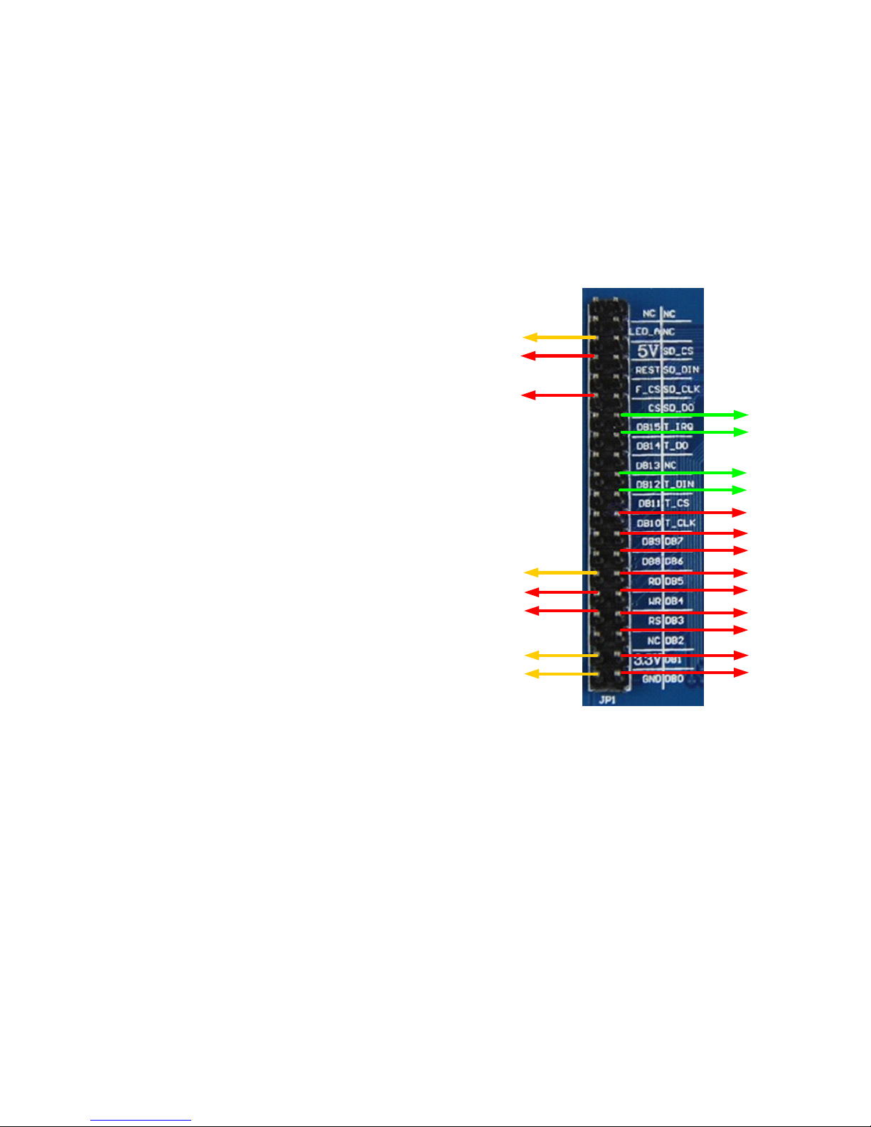
Micromite Plus Manual Page 41
3.3V
60
GROUND
61
62
63
64
1
2
3
24
27
5
18
4
21
47
5 Volts
28
GROUND
3.3V
Examples
Basic Explore 64 Configuration
To use the USB feature of the Explore 64 board you should check the requirements of your operating system
(see the section USB Console above). Then it should be simply a case of plugging the Explorer 64 USB into
your host computer, starting Tera Term or a similar terminal emulator and connecting to the virtual serial port
created by the Micromite Plus on your computer.
To use the SD Card on the Explore 64 board you should run the following command at the command prompt:
OPTION SDCARD 12, 14
To test the SD command you can run the command FILES which should list the files on your SD card.
SSD1963 Based Display Connection
First, ensure that the jumper on the SSD1963
controller board is moved from the pair of solder pads
marked LED-A to the pair marked 1963-PWM. This
will place the backlight brightness under the control of
SSD1963 chip (see "Connecting an SSD1963 Based
LCD Panel" earlier in this manual).
If the board does not have these jumpers you will have
to control the brightness via the LED-A pin as described
in the above referenced section.
Next, connect the Explore 64 I/O pins to the SSD1963
display connector as shown in the diagram to the right.
The power supply connections are shown in yellow, the
SSD1963 controller connections are in red and the
touch controller in green. Note that the touch Chip
Select signal (pin 14) must be configured in MMBasic
when using the SD card on the Explore 64 board.
Without this the pin will float causing the touch
controller to mistakenly respond to commands intended
for the SD card.
You need to configure MMBasic for the display. An
example is:
OPTION LCDPANEL SSD1963_7, L
This will configure the display as a 7" LCD panel in
the landscape orientation. If your display is not the 7" version you should change the display type to
SSD1963_4 or SSD1963_5 to suit your display.
To check that the LCD display panel is working correctly you can test it with the command:
GUI TEST LCDPANEL
You should see a rapid sequence of circles being drawn. Press the space bar to terminate the test.
Next, connect a pizeo buzzer from pin 50 of the Micromite Plus to ground (pin 50 has a 30mA drive capability
and this should be enough to operate most pizeo buzzers). This will be used be used to generate a click sound
when controls are touched, it is optional but the audible feedback makes using the advanced controls more
intuitive.
The touch controller must be made known to MMBasic and the following gives an example:
OPTION TOUCH 18, 21, 50
This specifies that the touch controller’s chip select is on pin 18, IRQ is on pin 21, and pin 50 is the click output.
To verify the configuration you can use the command OPTION LIST to list all options that have been set
including the configuration of the LCD panel and touch input.

Micromite Plus Manual Page 42
The touch controller then needs to be calibrated. To do this, enter this command and follow the on screen
prompts which will request a touch on all four corners of the display:
GUI CALIBRATE
Finally, you can test the touch feature with the command:
GUI TEST TOUCH
When you touch the screen a white mark should appear exactly under the location touched. You can even draw
on the screen to test your artistic skills !!
Keyboard and LCD Console
If you want to use the Micromite Plus and the SSD1963 display panel as a stand alone computer you can
connect a keyboard and send the console output to the LCD panel.
To connect the keyboard follow the connections listed in the section "Console Input/Output". The PS2 clock
signal (pin 5 on the DIN connector) should connect to pin 54 on the Micromite Explore 64 and the data signal
(pin 1 on the DIN connector) should connect to pin 55. The keyboard should also be connected to +5V and
ground.
Use the following command to configure the standard US layout and enable the keyboard:
OPTION KEYBOARD US
You can also direct the console output to the LCD panel with the command:
OPTION LCDPANEL CONSOLE
These options will be retained even when the power is removed so you can disconnect the serial or USB
console and use the keyboard and LCD panel as a self contained computer programmed in the BASIC language
(rather like the TRS-80 or Apple II of yesterday).
Example Program
As a test you can enter the following "Pump Control" demonstration program as shown in this YouTube video:
https://youtu.be/j12LidkzG2A. It will draw a selection of advanced controls on the screen that you can test.
Note that it expects a 800 x 480 pixel LCD panel in landscape orientation with touch (ie, a 5”, 7" or 8"
SSD1963 based panel)..
'''''''''''''''''''''''''''''''''''''''''''''''''''''''''''''''''
' Demonstration program for the Micromite+
' It does not do anything useful except demo the various controls
'
' Geoff Graham, October 2015
'''''''''''''''''''''''''''''''''''''''''''''''''''''''''''''''''
Option Explicit
Dim ledsY
Colour RGB(white), RGB(black)
' reference numbers for the controls are defined as constants
Const c_head = 1, c_pmp = 2, sw_pmp = 3, c_flow = 4, tb_flow = 5
Const led_run = 6, led_alarm = 7
Const frm_alarm = 20, nbr_hi = 21, nbr_lo = 22, pb_test =23
Const c_hi = 24, c_lo = 25
Const frm_pump = 30, r_econ = 31, r_norm = 32, r_hi = 33
Const frm_log = 40, cb_enabled = 41, c_fname = 42, tb_fname = 43
Const c_log = 44, cb_flow = 45, cb_pwr = 46, cb_warn = 47
Const cb_alarm = 48, c_bright = 49, sb_bright = 50
' now draw the "Pump Control" display
CLS
GUI Interrupt TouchDown, TouchUp
' display the heading
Font 2,2 : GUI Caption c_head, "Pump Control", 10, 0
Font 3 : GUI Caption c_pmp, "Pump", 20, 60, , RGB(brown)

Micromite Plus Manual Page 43
' now, define and display the controls
' first display the switch
Font 4
GUI Switch sw_pmp, "ON|OFF", 20, 90, 150, 50, RGB(white),RGB(brown)
CtrlVal(sw_pmp) = 1
' the flow rate display box
Font 3 : GUI Caption c_flow, "Flow Rate", 20, 170,, RGB(brown),0
Font 4 : GUI Displaybox tb_flow, 20, 200, 150, 45
CtrlVal(tb_flow) = "20.1"
' the radio buttons and their frame
Font 3 : GUI Frame frm_pump, "Power", 20, 290, 170, 163,RGB(200,20,255)
GUI Radio r_econ, "Economy", 43, 328, 12, RGB(230, 230, 255)
GUI Radio r_norm, "Normal", 43, 374
GUI Radio r_hi, "High", 43, 418
CtrlVal(r_norm) = 1 ' start with the "normal" button selected
' the alarm frame with two number boxes and a push button switch
Font 3 : GUI Frame frm_alarm, "Alarm", 220, 220, 200, 233,RGB(green)
GUI Caption c_hi, "High:", 232, 260, "LT", RGB(yellow)
GUI Numberbox nbr_hi, 318,MM.VPos-6,90,MM.FontHeight+12,RGB(yellow),RGB(64,64,64)
GUI Caption c_lo, "Low:", 232, 325, LT, RGB(yellow),0
GUI Numberbox nbr_lo, 318,MM.VPos-6,90,MM.FontHeight+12,RGB(yellow),RGB(64,64,64)
GUI Button pb_test, "TEST", 257, 383, 130, 40,RGB(yellow), RGB(red)
CtrlVal(nbr_lo) = 15.7 : CtrlVal(nbr_hi) = 35.5
' draw the two LEDs
Const ledsX = 255, coff = 50 ' define their position
ledsY = 105 : GUI LED led_run, "Running", ledsX, ledsY, 15, RGB(green)
ledsY = ledsY+49 : GUI LED led_alarm, "Alarm", ledsX, ledsY, 15, RGB(red)
CtrlVal(led_run) = 1 ' the switch defaults to on so set the LED on
' the logging frame with check boxes and a text box
Colour RGB(cyan), 0
GUI Frame frm_log, "Log File", 450, 20, 330, 355, RGB(green),0
GUI Checkbox cb_enabled, "Logging Enabled", 470, 50, 30, RGB(cyan)
GUI Caption c_fname, "File Name", 470, 105
GUI Textbox tb_fname, 470, 135, 290, 40, RGB(cyan), RGB(64,64,64)
GUI Caption c_log, "Record:", 470, 205, , RGB(cyan), 0
GUI Checkbox cb_flow, "Flow Rate", 500, 245, 25
GUI Checkbox cb_alarm, "Alarms", 500, 285, 25
GUI Checkbox cb_warn, "Warnings", 500, 325, 25
CtrlVal(cb_enabled) = 1
CtrlVal(tb_fname) = "LOGFILE.TXT"
' define and display the spinbox for controlling the backlight
GUI Caption c_bright, "Backlight", 442, 415, ,RGB(200,200,255),0
GUI Spinbox sb_bright, MM.HPos + 8, 400, 200, 50,,,10, 10, 100
CtrlVal(sb_bright) = 100
' All the controls have been defined and displayed. At this point
' the program could do some real work but because this is just a
' demo there is nothing to do. So it just sits in a loop.
Do : Loop
' the interrupt routine for touch down
' using a select case command it has a different process for each control
Sub TouchDown
Select Case Touch(REF) ' find out the control touched
Case cb_enabled ' the enable check box
If CtrlVal(cb_enabled) Then
GUI ENABLE c_fname, tb_fname, c_log, cb_flow, cb_alarm, cb_warn
Else
GUI Disable c_fname, tb_fname, c_log, cb_flow, cb_alarm, cb_warn
EndIf

Micromite Plus Manual Page 44
Case sb_bright ' the brightness spin box
BackLight CtrlVal(sb_bright)
Case sw_pmp ' the pump on/off switch
CtrlVal(led_run) = CtrlVal(sw_pmp)
CtrlVal(tb_flow) = Str$(CtrlVal(sw_pmp) * 20.1)
CtrlVal(r_norm) = 1
Case pb_test ' the alarm test button
CtrlVal(led_alarm) = 1
GUI beep 250
Case r_econ ' the economy radio button
CtrlVal(tb_flow) = Str$(CtrlVal(sw_pmp) * 18.3)
Case r_norm ' the normal radio button
CtrlVal(tb_flow) = Str$(CtrlVal(sw_pmp) * 20.1)
Case r_hi ' the high radio button
CtrlVal(tb_flow) = Str$(CtrlVal(sw_pmp) * 23.7)
End Select
End Sub
' interrupt routine when the touch is removed
Sub TouchUp
Select Case Touch(LASTREF) ' use the last reference
Case pb_test ' was it the test button
CtrlVal(led_alarm) = 0 ' turn off the LED
End Select
End Sub

Micromite Plus Manual Page 45
Read Only Variables (extra for the Micromite Plus Only)
Detailed Listing
MM.HPOS
MM.VPOS
The current horizontal and vertical position (in pixels) following the last graphics
or print command.
MM.ERRNO
Is set to the error number if a statement involving the SD card fails or zero if the
operation succeeds. This is dependent on the setting of OPTION ERROR. The
possible values for MM.ERRNO are:
0 = No error
1 = No SD card found
2 = SD card is write protected
3 = Not enough space
6 = Cannot find file
7 = Cannot find file or directory
8 = Cannot create directory
12 = Hardware error
13 = File system error
14 = Directory not empty
16 = Syntax or general programming error
Note that these error numbers and messages have changed with the introduction
of the advanced file access introduced in V5.4 however, for backwards
compatibility, the important error numbers (errors 1 and 6) have not changed.

Micromite Plus Manual Page 46
Commands (extra for the Micromite Plus Only)
Detailed Listing
BACKLIGHT percent
Controls the brightness of the LCD panel's backlight (SSD1963 based display
panels only). 'percent' is the degree of brightness ranging from 0 (fully off) to
100 (full brightness).
BLIT READ [#]b, x, y, w, h
BLIT WRITE [#]b, x, y, w, h
BLIT CLOSE [#]b
Copy one section of the display screen to or from a memory buffer.
BLIT READ will copy a portion of the display to the memory buffer '#b'. The
source coordinate is 'x' and 'y' and the width of the display area to copy is 'w'
and the height is 'h'. When this command is used the memory buffer is
automatically created and sufficient memory allocated. This buffer can be
freed and the memory recovered with the BLIT CLOSE command.
BLIT WRITE will copy the memory buffer '#b' to the display. The destination
coordinate is 'x' and 'y' and the width/height of the buffer to copy is 'w' and 'h'.
BLIT CLOSE will close the memory buffer '#b' to allow it to be used for
another BLIT READ operation and recover the memory used.
Notes:
Eight buffers are available ranging from #1 to #8.
When specifying the buffer number the # symbol is optional.
All other arguments are in pixels.
The display must use the ILI9341 controller or the SSD1963 controller
with the RD (read) pin connected (or VGA on the Micromite eXtreme).
BLIT x1, y1, x2, y2, w, h Copy one section of the display screen to another part of the display.
The source coordinate is 'x1' and 'y1'. The destination coordinate is 'x2' and
'y2'. The width of the screen area to copy is 'w' and the height is 'h'.
All arguments are in pixels. The source and destination can overlap. The
display must use the ILI9341 controller or the SSD1963 controller with the RD
(read) pin connected.
CHDIR dir$ Change the current working directory on the SD card to ‘dir$’
The special entry “..” represents the parent of the current directory and “.”
represents the current directory.
CLOSE [#]fnbr [,[#]fnbr] … Close the file(s) previously opened with the file number ‘#fnbr’. The # is
optional. Also see the OPEN command.
CTRLVAL(#ref) = This command will set the value of an advanced control.
'#ref' is the control's reference (a number from 1 to 100).
For off/on controls like check boxes it will override any touch input and can be
used to depress/release switches, tick/untick check boxes, etc. A value of zero
is off or unchecked and non zero will turn the control on. For a LED it will
cause the LED to be illuminated or turned off. It can also be used to set the
initial value of spin boxes, text boxes, etc.
For example:
CTRLVAL(#10) = 12.4
FILES [fspec$] Lists files in the current directory on the SD card.
'fspec$' (if specified) can contain search wildcards. Question marks (?) will
match any character and an asterisk (*) will match any number of characters. If
omitted, all files will be listed. For example:
*.* Find all entries
*.TXT Find all entries with an extension of TXT
E*.* Find all entries starting with E
X?X.* Find all three letter file names starting and ending with X

Micromite Plus Manual Page 47
GUI AREA #ref, startX,
startY, width, height
This will define an invisible area of the screen that is sensitive to touch and will
generate touch down and touch up interrupts. It can be used as the basis for
creating custom controls which are defined and managed by the program.
'#ref' is the control's reference (a number from 1 to 100). 'startX' and 'startY'
are the top left coordinates while 'width' and 'height' set the dimensions.
GUI BCOLOUR colour,
#ref1 [, #ref2, #ref3, etc]
This will change the background colour of the specified controls to 'colour'
which is an RGB value for the drawing colour.
'#ref' is the control's reference (a number from 1 to 100).
GUI BEEP msec
This will sound the pizeo buzzer if configured with the OPTION TOUCH
command.
'msec' is the number of milliseconds that the buzzer should be driven. A time
of 3ms produces a click while 100ms produces a short beep.
GUI BUTTON #ref,
caption$, startX, startY,
width, height [, FColour]
[,BColour]
This will draw a momentary button which is a square switch with the caption
on its face.
When touched the visual image of the button will appear to be depressed and
the control's value will be 1. When the touch is removed the value will revert
to zero.
#ref' is the control's reference (a number from 1 to 100).
'caption$' is the string to display on the face of the button. It can be a single
string with two captions separated by a | character (eg, "UP|DOWN"). When
the button is up the first string will be used and when pressed the second will be
used.
'startX' and 'startY' are the top left coordinates while 'width' and 'height' set the
dimensions. ' FColour and 'BColour' are RGB values for the foreground and
background colours.
'width', 'height', FColour and 'BColour' are optional and default to that used in
previous controls or set with the COLOUR command.
GUI CAPTION #ref, text$,
startX, startY [, justify$]
[, FColour] [, BColour]
This will draw a text string on the screen.
'#ref' is the control's reference (a number from 1 to 100).
'text$' is the string to display. 'startX' and 'startY' are the top left coordinates.
'justify$' is zero to three characters (a string expression or variable is also
allowed) where the first letter is the horizontal justification around X and can be
L, C or R for LEFT, CENTER, RIGHT and the second letter is the vertical
placement around Y and can be T, M or B for TOP, MIDDLE, BOTTOM. A
third character can be used in the justification to indicate the rotation of the text.
This can be 'N' for normal orientation, 'V' for vertical text with each character
under the previous running from top to bottom, 'I' the text will be inverted (ie,
upside down), 'U' the text will be rotated counter clockwise by 90º and 'D' the
text will be rotated clockwise by 90º. The default justification is left/top with
no rotation.
'FColour and 'BColour' are RGB values for the foreground and background
colours on a display that supports transparent text BColour can be -1 which
means that the background will show through the gaps in the characters.
FColour and 'BColour' are optional and default to the colours set by the
COLOUR command.
Micromite Plus Manual Page 48
GUI CHECKBOX #ref,
caption$, startX, startY [,
size] [, colour]
This will draw a check box which is a small box with a caption. When touched
an X will be drawn inside the box to indicate that this option has been selected
and the control's value will be set to 1. When touched a second time the check
mark will be removed and the control's value will be zero.
'#ref' is the control's reference (a number from 1 to 100).
The string 'caption$' will be drawn to the right of the control using the colours
set by the COLOUR command.
'startX' and 'startY' are the top left coordinates while 'size' set the height and
width (the bix is square). 'colour' is an RGB value for the drawing colour. 'size'
and 'colour' are optional and default to that used in previous controls.
GUI DELETE #ref1 [,#ref2,
#ref3, etc]
or
GUI DELETE ALL
This will delete the controls in the list. This includes removing the image of the
control from the screen using the current background colour and freeing the
memory used by the control.
'#ref' is the control's reference (a number from 1 to 100). The keyword ALL
can be used as the argument and that will disable all controls.
GUI DISABLE #ref1
[,#ref2, #ref3, etc]
or
GUI DISABLE ALL
This will disable the controls in the list. Disabled controls do not respond to
touch and will be displayed dimmed.
'#ref' is the control's reference (a number from 1 to 100). The keyword ALL
can be used as the argument and that will disable all controls.
GUI ENABLE can be used to restore the controls.
GUI DISPLAYBOX #ref,
startX, startY, width, height,
FColour, BColour
This will draw a box with rounded corners that can be used to display a string
'#ref' is the control's reference (a number from 1 to 100).
'startX' and 'startY' are the top left coordinates while 'width' and 'height' set the
dimensions. ' FColour and 'BColour' are RGB values for the foreground and
background colours. 'width', 'height', FColour and 'BColour' are optional and
default to that used in previous controls.
Any text can be displayed in the box by using the CtrlVal(r) = command. This
is useful for displaying text, numbers and messages.
This control does not respond to touch.
GUI ENABLE #ref1
[,#ref2, #ref3, etc]
or
GUI ENABLE ALL
This will undo the effects of GUI DISABLE and restore the control(s) to
normal operation.
'#ref' is the control's reference (a number from 1 to 100). The keyword ALL
can be used as the argument and that will disable all controls.
GUI FCOLOUR colour,
#ref1 [, #ref2, #ref3, etc]
This will change the foreground colour of the specified controls to 'colour'
which is an RGB value for the drawing colour.
'#ref' is the control's reference (a number from 1 to 100).
GUI FRAME #ref,
caption$, startX, startY,
width, height, colour
This will draw a frame which is a box with round corners and a caption.
'#ref' is the control's reference (a number from 1 to 100).
'caption$' is a string to display as the caption. 'startX' and 'startY' are the top
left coordinates while 'width' and 'height' set the dimensions. 'colour' is an RGB
value for the drawing colour. 'width', 'height' and 'colour' are optional and
default to that used in previous controls.
A frame is useful when a group of controls need to be visually brought together.
It is also used to surround a group of radio buttons and MMBasic will arrange
for the radio buttons surrounded by the frame to be exclusive. ie, when one
radio button is selected any other button that was selected and within the frame
Micromite Plus Manual Page 49
will be automatically deselected.
A frame does not respond to touch.
GUI HIDE #ref1 [,#ref2,
#ref3, etc]
or
GUI HIDE ALL
This will hide the controls in the list. Hidden controls do not respond to touch
and will not be visible.
'#ref' is the control's reference (a number from 1 to 100). The keyword ALL
can be used as the argument and that will hide all controls.
GUI SHOW can be used to restore the controls.
GUI INTERRUPT down [,
up]
This command will setup an interrupt that will be triggered on a touch on the
LCD panel and optionally if the touch is released.
'down' is the subroutine to call when a touch down has been detected. 'up' is the
subroutine to call when the touch has been lifted from the screen ('up' and
'down' can point to the same subroutine if required).
Specifying the number zero (single digit) as the argument will cancel both of
these interrupts. ie:
GUI INTERRUPT 0
GUI LED #ref, caption$,
centerX, centerY, radius,
colour
This will draw an indicator light which looks like a panel mounted LED. A
LED does not respond to touch.
'#ref' is the control's reference (a number from 1 to 100).
The string 'caption$' will be drawn to the right of the control using the colours
set by the COLOUR command.
'centerX' and 'centerY' are the coordinates of the centre of the LED and 'radius'
is the radius of the LED. 'colour' is an RGB value for the drawing colour.
'radius' and 'colour' are optional and default to that used in previous controls.
When a LED's value is set to a value of one it will be illuminated and when it is
set to zero it will be off (a dull version of its colour attribute). The LED can be
made to flash on then off by setting the value of the LED to a number greater
than one which is the time in milliseconds that it should remain on.
The colour can be changed with the GUI FCOLOUR command.
GUI NUMBERBOX #ref,
startX, startY, width, height,
FColour, BColour
This will draw a box with rounded corners that can be used to create a virtual
numeric keypad for data entry.
'#ref' is the control's reference (a number from 1 to 100).
'startX' and 'startY' are the top left coordinates while 'width' and 'height' set the
dimensions. ' FColour and 'BColour' are RGB values for the foreground and
background colours. 'width', 'height', FColour and 'BColour' are optional and
default to that used in previous controls.
When the box is touched a numeric keypad will appear on the screen. Using
this virtual keypad any number can be entered into the box including a floating
point number in exponential format. The new number will replace the number
previously in the box.
The value of the control can set to a literal string (not an expression) starting
with two hash characters. For example:
CtrlVal(nnn) = "##Enter Number"
and in that case the string (without the leading two hash characters) will be
displayed in the box with reduced brightness. This can be used to give the user
a hint as to what should be entered (called "ghost text"). Reading the value of
the control displaying ghost text will return zero. When the control is used
normally the ghost text will vanish.
MMBasic will try to position the virtual keypad on the screen so as to not
obscure the number box that caused it to appear. A pen down interrupt will be
Micromite Plus Manual Page 50
generated when the keypad is deployed and a key up interrupt will be generated
when the Enter key is touched and the keypad is hidden. Also, when the Enter
key is touched the entered number will be evaluated as a number and the
NUMBERBOX control redrawn to display this number.
If a subroutine with the name MM.KEYPRESS exists in the program it will be
called by this control after each key press. The control's reference number (an
integer) and the caption on the key (a string) are supplied as parameters.
GUI NUMBERBOX
CANCEL
This will dismiss a virtual keypad if it is displayed on the screen. It is the same
as if the user touched the cancel key except that the touch up interrupt is not
generated. If a keypad is not displayed this command will do nothing.
GUI RADIO #ref, caption$,
centerX, centerY, radius,
colour
This will draw a radio button with a caption.
'#ref' is the control's reference (a number from 1 to 100).
The string 'caption$' will be drawn to the right of the control using the colours
set by the COLOUR command.
'centerX' and 'centerY' are the coordinates of the centre of the button and
'radius' is the radius of the button. 'colour' is an RGB value for the drawing
colour. 'radius' and 'colour' are optional and default to that used in previous
controls.
When touched the centre of the button will be illuminated to indicate that this
option has been selected and the control's value will be 1. When another radio
button is selected the mark on this button will be removed and its value will be
zero. Radio buttons are grouped together when surrounded by a frame and
when one button in the group is selected all others in the group will be
deselected. If a frame is not used all buttons on the screen will be grouped
together.
GUI REDRAW #ref1
[,#ref2, #ref3, etc]
or
GUI REDRAW ALL
This will redraw the controls on the screen. It is useful if the screen image has
somehow been corrupted.
'#ref' is the control's reference (a number from 1 to 100). The keyword ALL
can be used as the argument and that will disable all controls.
GUI SETUP #n
This will allocate any new controls created to the page '#n'.
This command can be used as many times as needed while GUI controls are
being defined. The default when a program starts running is GUI SETUP 1.
See also the GUI PAGE command.
GUI SHOW #ref1 [,#ref2,
#ref3, etc]
or
GUI SHOW ALL
This will undo the effects of GUI HIDE and restore the control(s) to being
visible and capable of normal operation.
'#ref' is the control's reference (a number from 1 to 100). The keyword ALL
can be used as the argument and that will disable all controls.
GUI SPINBOX #ref, startX,
startY, width, height,
FColour, BColour, Step,
Minimum, Maximum
This will draw a box with up/down icons on either end. When these icons are
touched the number in the box will be incremented or decremented. Holding
down the up/down icons will repeat the step at a fast rate.
'#ref' is the control's reference (a number from 1 to 100).
'startX' and 'startY' are the top left coordinates while 'width' and 'height' set the
dimensions. ' FColour and 'BColour' are RGB values for the foreground and
background colours.
'width', 'height', FColour and 'BColour' are optional and default to that used in
previous controls.
'Step' sets the amount to increment/decrement the number with each touch.
Micromite Plus Manual Page 51
'Minimum' and 'Maximum' set limits on the number that can be entered. All
three parameters can be floating point numbers and are optional. The default
for 'Step' is 1 and 'Minimum' and 'Maximum' if omitted will default to no limit.
GUI SWITCH #ref,
caption$, startX, startY,
width, height, FColour,
BColour
This will draw a latching switch which is a square switch that latches when
touched.
'#ref' is the control's reference (a number from 1 to 100).
'caption$' is a string to display as the caption on the face of the switch. 'startX'
and 'startY' are the top left coordinates while 'width' and 'height' set the
dimensions. ' FColour and 'BColour' are RGB values for the foreground and
background colours. 'width', 'height', FColour and 'BColour' are optional and
default to that used in previous controls.
When touched the visual image of the button will appear to be depressed and
the control's value will be 1. When touched a second time the switch will be
released and the value will revert to zero. Caption can consist of two captions
separated by a | character (eg, "ON|OFF"). When this is used the switch will
appear to be a toggle switch with each half of the caption used to label each half
of the toggle switch.
GUI TEXTBOX #ref,
startX, startY, width, height,
FColour, BColour
This will draw a box with rounded corners that can be used to create a virtual
keyboard for data entry
'#ref' is the control's reference (a number from 1 to 100).
'startX' and 'startY' are the top left coordinates while 'width' and 'height' set the
dimensions. ' FColour and 'BColour' are RGB values for the foreground and
background colours. 'width', 'height', FColour and 'BColour' are optional and
default to that used in previous controls.
When the box is touched a QWERTY keyboard will appear on the screen.
Using this virtual keyboard any text can be entered into the box including
upper/lower case letters, numbers and any other characters in the ASCII
character set. The new text will replace any text previously in the box.
The value of the control can set to a string starting with two hash characters.
For example:
CtrlVal(nnn) = "##Enter Filename"
and in that case the string (without the leading two hash characters) will be
displayed in the box with reduced brightness. This can be used to give the user
a hint as to what should be entered (called "ghost text"). Reading the value of
the control displaying ghost text will return an empty string. When the control
is used normally the ghost text will vanish.
MMBasic will try to position the virtual keyboard on the screen so as to not
obscure the text box that caused it to appear. A pen down interrupt will be
generated when the keyboard is deployed and a key up interrupt will be
generated when the Enter key is touched and the keyboard is hidden.
If a subroutine with the name MM.KEYPRESS exists in the program it will be
called by this control after each key press. The control's reference number (an
integer) and the caption on the key (a string) are supplied as parameters.
GUI TEXTBOX CANCEL
This will dismiss a virtual keyboard if it is displayed on the screen. It is the
same as if the user touched the cancel key except that the touch up interrupt is
not generated. If a keyboard is not displayed this command will do nothing.
INPUT #fnbr,
list of variables
Same as the normal INPUT command except that the input is read from a file
previously opened for INPUT as ‘#fnbr’. See the OPEN command.
KILL file$ Deletes the file specified by ‘file$’. If there is an extension it must be specified.
Micromite Plus Manual Page 52
LINE INPUT #fnbr,
string-variable$
Same as the LINE INPUT command except that the input is read from a file
previously opened for INPUT as ‘#fnbr’. See the OPEN command.
LOAD file$ [,R]
Loads a program called ‘file$’ from the current drive into program memory. If
the optional suffix ,R is added the program will be immediately run without
prompting.
If an extension is not specified “.BAS” will be added to the file name.
LOAD IMAGE file$ [, x, y]
Load a bitmapped image from the SD card and display it on the LCD panel.
''file$' is the name of the file and 'x' and 'y' are the screen coordinates for the top
left hand corner of the image. If the coordinates are not specified the image
will be drawn at the top left hand position on the screen.
If an extension is not specified “.BMP” will be added to the file name.
All types of the BMP format are supported including black and white and true
colour 24-bit images.
MKDIR dir$ Make, or create, the directory ‘dir$’ on the SD card.
OPEN fname$ FOR mode
AS [#]fnbr
Opens a file for reading or writing.
‘fname’ is the filename with an optional extension separated by a dot (.). Long
file names with upper and lower case characters are supported.
A directory path can be specified with the backslash as directory separators.
The parent of the current directory can be specified by using a directory name
of .. (two dots) and the current directory with . (a single dot).
For example OPEN "..\dir1\dir2\filename.txt" FOR INPUT AS #1
‘mode’ is INPUT, OUTPUT, APPEND or RANDOM.
INPUT will open the file for reading and throw an error if the file does not
exist. OUTPUT will open the file for writing and will automatically overwrite
any existing file with the same name.
APPEND will also open the file for writing but it will not overwrite an existing
file; instead any writes will be appended to the end of the file. If there is no
existing file the APPEND mode will act the same as the OUTPUT mode (i.e.
the file is created then opened for writing).
RANDOM will open the file for both read and write and will allow random
access using the SEEK command. When opened the read/write pointer is
positioned at the end of the file.
‘fnbr’ is the file number (1 to 10). The # is optional. Up to 5 files can be open
simultaneously. The INPUT, LINE INPUT, PRINT, WRITE and CLOSE
commands as well as the EOF() and INPUT$() functions all use ‘fnbr’ to
identify the file being operated on.
See also OPTION ERROR and MM.ERRNO for error handling.
OPTION CONTROLS nn
Set the maximum number of controls that can be created by a program to 'nn'.
This can be any number from 1 to 1000. The default is 100. A larger number
will use more RAM (each control entry uses about 50 bytes of RAM).
This command can only be run from the command line and the new value will
remembered, even when the power is cycled or a new program loaded.
OPTION ERROR
CONTINUE
or
OPTION ERROR ABORT
Set the treatment for errors in file input/output on the SD card. The option
CONTINUE will cause MMBasic to ignore file related errors. The program
must check the variable MM.ERRNO to determine if and what error has
occurred.
The option ABORT sets the normal behaviour (ie, stop the program and print
an error message). The default is ABORT.
Note that this entry only relates to errors reading from or writing to the SD
card. See the ON ERROR command in the Micromite User Manual for
handling syntax and other program errors.

Micromite Plus Manual Page 53
OPTION KEYBOARD nn Enable an attached PS2 keyboard and set its language type.
‘nn is a two character code defining the keyboard layout. The choices are US
for the standard keyboard layout in the USA, Australia and New Zealand , UK
(United Kingdom), FR (French), GR (German), BE (Belgium), IT (Italian) or
ES (Spanish). OPTION KEYBOARD DISABLE will disable the keyboard and
return the I/O pins to normal use.
See the section "PS2 Keyboard" for details of connecting the keyboard.
This command can only be run from the command line and the new value will
remembered, even when the power is cycled or a new program loaded.
OPTION LCDPANEL
controller, orientation, D/C
pin, reset pin [,CS pin]
or
OPTION LCDPANEL
controller, orientation
[,LCD-A pin]
or
OPTION LCDPANEL
DISABLE
Configures the Micromite Plus to work with an attached LCD panel.
'controller' can be:
ILI9163 SPI based 1.44" panels using the ILI9163 controller
ST7735 SPI based 1.8" panels using the ST7735 controller
ILI9341 SPI based 2.2", 2.4" and 2.8" panels using the ILI9341
controller
SSD1963_4 4.3" panels using the SSD1963controller
SSD1963_5 5" panels using the SSD1963controller
SSD1963_5A alternative version of the 5" panel
SSD1963_7 7" panels using the SSD1963controller
SSD1963_7A alternative version of the 7" panel
SSD1963_8 8" panels using the SSD1963controller
'orientation' can be LANDSCAPE, PORTRAIT, RLANDSCAPE or
RPORTRAIT. These can be abbreviated to L, P, RL or RP. The R prefix
indicates the reverse or "upside down" orientation.
ILI9341, ST7735 and ILI9163 based panels:
'C/D pin' and 'reset pin' are the Micromite I/O pins to be used for these functions.
Any free pin can be used. 'CS pin' can also be any I/O pin but is optional. If a
touch controller is not used this parameter can be left off the command and the
CS pin on the LCD display wired permanently to ground. If the touch controller
is used this pin must then be specified and connected to a Micromite I/O pin.
NOTE: The CPU speed must be 20MHz or greater.
For SSD1963 based panels:
'LCD-A pin' can also be any I/O pin but is optional. This can be used to control
the brightness of the backlight if the internal SSD1963 controller is not used.
This command only needs to be run once as the parameters are stored in non
volatile memory. When the Micromite is restarted the display will be
automatically initialise ready for use. If the LCD panel is no longer required the
command OPTION LCDPANEL DISABLE can be used to disable the LCD
panel feature and return the I/O pins for general use.
OPTION LCDPANEL
CONSOLE [font [, fc [,bc
blight]]]
or
OPTION LCDPANEL
NOCONSOLE
Configures the LCD display panel for use as the console output.
The LCD must be one of the SSD1963 versions in the landscape or reverse
landscape orientation and it must be first configured using OPTION
LCDPANEL SSD1963_x (above).
'font' is the default font, 'fc' is the default foreground colour, 'bc' is the default
background colour and 'blight' is the default backlight brightness (2 to 100).
These parameters are optional and default to font 2, white, black and 100%.
These settings are applied at power up.
Colour coding in the editor is also turned on by this command (OPTION
COLOURCODE OFF will turn it off again).
This setting is saved in flash and will be automatically applied on startup. To
disable it use the OPTION LCDPANEL NOCONSOLE command.

Micromite Plus Manual Page 54
OPTION RTC Data-pin,
Clock-pin
or
OPTION RTC DISABLE
Configures the Micromite Plus for access to a Real Time Clock (RTC).
'Data-pin' is the I/O pin number used for the I2C data line and Clock-pin is the
same for the I2C clock. If they are the same as the standard I2C interface then that
interface will be used. If they are different a private I2C interface will be created
to communicate with the RTC (this frees up the main I2C interface for other
tasks).
When this command is used the settings will be saved in non volatile memory
and automatically applied at startup or reset. Also on startup MMBasic will
automatically query the RTC for the current time and date and set the internal
clock (similar to the RTC GETTIME command).
The general commands for accessing the RTC (RTC SETTIME, RTC GETREG,
etc) can still be used and will access the RTC connected to the I/O pins specified
in this command.
The command OPTION RTC DISABLE can be used to disable this feature and
return the I/O pins for general use.
OPTION SDCARD CS-pin
[, CD-pin [,WP pin]]
or
OPTION SDCARD
DISABLE
Configures the Micromite Plus to access an attached SD card.
'CS-pin' is the I/O pin number that will be used as chip select (pin 1 on the SD
card connector).
'CD-pin' is optional and is the I/O pin number that will be used to connect to the
card detect pin on the SD card connector. The Micromite will provide a weak
pullup on this pin which is switched to ground when a card is inserted. If this
signal is not provided the Micromite Plus will need to be restarted if the SD card
was changed.
'WP-pin' is optional and is the I/O pin number that will be used to connect to the
write protect pin on the SD card connector. The Micromite will provide a weak
pullup on this pin which is switched to ground when a write protected card is
inserted.
Some SD card connectors reverse the polarity of the 'CD-pin' or 'WP-pin' signal -
ie, they are open (and therefore the signal is high) when the card is inserted or
write protected. In this case the pin numbers used for 'CD-pin' and 'WP-pin' can
be a negative number. This will tell MMBasic to invert the polarity of these
signals.
This command only needs to be run once. When the Micromite is restarted
MMBasic will automatically initialise the SD card interface. If the SD card is no
longer required the command OPTION SDCARD DISABLE can be used
which will disable the SD card and return the I/O pins for general use.
OPTION TOUCH T_CS
pin, T_IRQ pin [, click pin]
or
OPTION TOUCH
DISABLE
Configures the Micromite Plus to suit the touch sensitive feature of an attached
LCD panel.
'T_CS pin' and 'T_IRQ pin' are the Micromite I/O pins to be used for chip select
and touch interrupt respectively (any free pins can be used).
'click pin' specifies an optional I/O pin that will be driven briefly high when a
screen control is touched. This can be used to drive a small Piezo buzzer.
This command only needs to be run once as the parameters are stored in non
volatile memory. Every time the Micromite is restarted MMBasic will
automatically initialise the touch controller. If the touch facility is no longer
required the command OPTION TOUCH DISABLE can be used to disable the
touch feature and return the I/O pins for general use.
PAGE #n [,#n2, #n3, etc]
This will switch the display to show controls that have been assigned (via the
GUI SETUP command) to the page numbers specified on the command line
(#n, #n2, etc). Any controls that were displayed but are not on the current list
of pages will be automatically hidden.
Any controls on a page that was displayed on the old screen and is also
specified in the new PAGE command will remain unaffected.
The default when a program starts running is PAGE 1 and GUI SETUP 1. This
Micromite Plus Manual Page 55
means that if these commands are not used the program will run as normal
showing all GUI controls that have been defined.
See also the GUI SETUP command.
PLAY TONE left [, right [,
dur]]
Generates two separate sine waves on the sound output left and right channels.
The sound output is stereo with the pin allocated to PWM 2A as the left channel
and PWM 2B as the right channel. The output is a pulse width modulated
signal so a low pass filter is required to remove the carrier frequency. See the
section Sound Output in this manual for the details.
'left' and 'right' are the frequencies in Hz to use for the left and right channels.
The tone plays in the background (the program will continue running after this
command) and 'dur' specifies the number of milliseconds that the tone will
sound for. If the duration is not specified the tone will continue until explicitly
stopped or the program terminates.
The frequency can be from 1Hz to 20KHz and is very accurate (it is based on
the PIC32 crystal oscillator). The frequency can be changed at any time by
issuing a new PLAY TONE command.
PLAY WAV file$ [,
interrupt]
Will play a WAV file on the sound output.
The sound output is stereo with the pin allocated to PWM 2A as the left channel
and PWM 2B as the right channel. The output is a pulse width modulated
signal so a low pass filter is required to remove the carrier frequency. See the
section Sound Output in this manual for the details.
'file$' is the WAV file to play (the extension of .wav will be appended if
missing). The WAV file must be PCM encoded in stereo with 8-bit sampling.
The sample rate can be 8KHz or 16kHz.
The WAV file is played in the background. 'interrupt' is optional and is the
name of a subroutine which will be called when the file has finished playing.
PLAY PAUSE
PLAY RESUME
PLAY STOP
PLAY PAUSE will temporarily halt the currently playing file or tone.
PLAY RESUME will resume playing a sound that was paused.
PLAY STOP will terminate the playing of the file or tone. When the program
terminates for whatever reason the sound output will also be automatically
stopped.
PLAY VOLUME left, right Will adjust the volume of the audio output.
'left' and 'right' are the levels to use for the left and right channels and can be
between 0 and 100 with 100 being the maximum volume. There is a linear
relationship between the specified level and the output.
The volume defaults to maximum when a program is run.
PRINT #fnbr, expression
[[,; ]expression] … etc
Same as the normal PRINT command except that the output is directed to a file
previously opened for OUTPUT or APPEND as ‘#fnbr’. See the OPEN
command.
RMDIR dir$ Remove, or delete, the directory ‘dir$’ on the SD card.
SAVE [ file$ ]
Saves the program in the current working directory of the SD card as ‘file$’.
Example: SAVE “TEST.BAS”
If an extension is not specified “.BAS” will be added to the file name.
SAVE IMAGE file$ Save the current image on the LCD panel as a BMP file.
'file$' is the name of the file. If an extension is not specified “.BMP” will be
added to the file name.
The image is saved as a true colour 24-bit image.
SEEK [#]fnbr, pos
Will position the read/write pointer in a file that has been opened on the SD
card for RANDOM access to the 'pos' byte.
The first byte in a file is numbered one so SEEK #5,1 will position the
read/write pointer to the start of the file.

Micromite Plus Manual Page 56
TRIANGLE X1, Y1, X2,
Y2, X3, Y3 [, C [, FILL]]
Draws a triangle on the LCD display panel with the corners at X1, Y1 and X2,
Y2 and X3, Y3. 'C' is the colour of the triangle and defaults to the current
foreground colour. 'FILL' is the fill colour and defaults to no fill (it can also be
set to -1 for no fill).

Micromite Plus Manual Page 57
Functions (extra for the Micromite Plus Only)
Detailed Listing
CTRLVAL(#ref) Returns the current value of an advanced control.
'#ref' is the control's reference (a number from 1 to 100).
For controls like check boxes or switches it will be the number one (true)
indicating that the control has been selected by the user or zero (false) if not.
For controls that hold a number (eg, a SPINBOX) the value will be the number
(normally a floating point number). For controls that hold a string (eg,
TEXTBOX) the value will be a string.
CWD$ Returns the current working directory on the SD card as a string.
The format is: A:/dir1/dir2.
DIR$( fspec, type )
or
DIR$( fspec )
or
DIR$( )
Will search an SD card for files and return the names of entries found.
'fspec' is a file specification using wildcards the same as used by the FILES
command. Eg, "*.*" will return all entries, "*.TXT" will return text files.
'type' is the type of entry to return and can be one of:
VOL Search for the volume label only
DIR Search for directories only
FILE Search for files only (the default if 'type' is not specified)
The function will return the first entry found. To retrieve subsequent entries
use the function with no arguments. ie, DIR$( ). The return of an empty
string indicates that there are no more entries to retrieve.
This example will print all the files in a directory:
f$ = DIR$("*.*", FILE)
DO WHILE f$ <> ""
PRINT f$
f$ = DIR$()
LOOP
You must change to the required directory before invoking this command.
EOF( [#]fnbr )
Will return true if the file previously opened on the SD card for INPUT with
the file number ‘#fnbr’ is positioned at the end of the file.
The # is optional. Also see the OPEN, INPUT and LINE INPUT commands
and the INPUT$ function.
EVAL( string$ )
Will evaluate 'string$' as if it is a BASIC expression and return the result.
'string$' can be a constant, a variable or a string expression. The expression can
use any operators, functions, variables, subroutines, etc that are known at the
time of execution. The returned value will be an integer, float or string
depending on the result of the evaluation.
For example: S$ = "COS(RAD(30)) * 100" : PRINT EVAL(S$)
Will display: 86.6025
INPUT$(nbr, [#]fnbr)
Will return a string composed of ‘nbr’ characters read from a file on the SD
card previously opened for INPUT with the file number ‘#fnbr’. This function
will read all characters including carriage return and new line without
translation.
The # is optional. Also see the OPEN command.
Micromite Plus Manual Page 58
LOC( [#]fnbr )
For a file on the SD card opened as RANDOM this will return the current
position of the read/write pointer in the file. Note that the first byte in a file is
numbered 1. The # is optional.
LOF( [#]fnbr )
For a file on the SD card this will return the current length of the file in bytes.
The # is optional.
MSGBOX (msg$, b1$
[,b2$ … b4$])
This function will display a message box on the screen with one to four touch
sensitive buttons. All other controls will be disabled until the user touches one
of the buttons. The message box will then be erased, the previous controls will
be restored and the function will return the number of the button touched (the
first button is number one)
'msg$' is the message to display. This can contain one or more tilde characters
(~) which indicate a line break. Up to 10 lines can be displayed inside the box.
'b1$' is the caption for the first button, 'b2$' is the caption for the second
button, etc. At least one button must be specified and four is the maximum.
Any buttons not included in the argument list will not be displayed.
PIXEL( x, y )
Returns the colour of a pixel on an attached LCD display panel. 'x' is the
horizontal coordinate and 'y' is the vertical coordinate of the pixel.
See the chapter "Basic Drawing Commands" for a definition of the colours and
graphics coordinates.
This function is only available on displays that use the ILI9341 controller or an
SSD1963 controller. The latter must have the RD pin specified in the OPTION
LCDPANEL command. On the Micromite eXtreme the VGA output also
supports this function (see the Micromite eXtreme Manual).
TOUCH(DOWN) Will return true if the screen is currently being touched.
TOUCH(UP) Will return true if the screen is currently NOT being touched.
TOUCH(LASTX) Will return the X coordinate of the last location that was touched.
TOUCH(LASTY) Will return the Y coordinate of the last location that was touched.
TOUCH(REF)
Will return the reference number of the control that is currently being touched
or zero if no control is being touched.
TOUCH(LASTREF) Will return the reference number of the last control that was touched.
 Loading...