

MicroMetl ECD-SRT12TA-D2, ECD-SRT34TA-D2, ECD-SRT05TA-D2 Installation Instructions Manual
MicroMetl
Small Rooftop Products
Select 3 to 12 ½ Tons
Accessory Ultra Low Leak Vertical Economizer
Installation Instructions
ECD-SRT12TA-D2, ECD-SRT34TA-D2, ECD-SRT05TA-D2 Series
*QR Code
Read these instructions completely before attempting to install the Vertical
Accessory Ultra Low Leak Economizer.
CONTENTS
Safety Consideration . . . . . . . . . . . . . . . . . . . . .1
General. . . . . . . . . . . . . . . . . . . . . . . . . . . . . . . . . . . .1
Economizer Sensor Usage. . . . . . . . . . . . . . . . . . . . .2
Accessories List. . . . . . . . . . . . . . . . . . . . . . . . . . . . . .2
Wiring Diagrams. . . . . . . . . . . . . . . . . . . . . . . . . . . . . .5-7
Installation . . . . . . . . . . . . . . . . . . . . . . . . . . . . . . . . .2-8
W7220 Menu Structure. . . . . . . . . . . . . . . . . . . . .9-12
Controller Setup and Conguration. . . . . . . .13-15
Operation. . . . . . . . . . . . . . . . . . . . . . . . . . . . . . . .16
Troubleshooting. . . . . . . . . . . . . . . . . . . . . . . . . . . .17
Barometric Relief and Return Pressure
Drop. . . . . . . . . . . . . . . . . . . . . . . . . . . . . . . . . . . . . . . . . . . . .18
*Jade W7220 Controller Addendum
*Certicate of Acceptance
Use QR Code Above to Access
SAFETY CONSIDERATIONS
Installation and servicing of air-conditioning equipment can be
hazardous dur to system pressure and electrical components. Only
trained and qualied service personnel should install, repair, or
service air-conditioning equipment.
Untrained personnel can perform the basic maintenance funtions.
All other operations should be performed by trained service
personnel. When working on air-conditioning equipment, observe
precautions in the literature, tags, and labels attached to the unit,
and other safety precautions that may apply.
Follow allsafety codes. Wear safety glasses and work gloves. Use
quenching cloth for unbrazing operations.
It is important to recognize safety information. This is the safetyalert symbol . When you see this symbol on the unit and in
instructions or manuals, be alert to the potential for personal injury.
Table 1
!
California
& ASHRAE
Code
Compliant
Understand the signal words DANGER, WARNING, CAUTION,
and NOTE. These words are used with the safety-alert symbol.
DANGER identies the most serious hazards which will result
in severe personal injury or death. WARNING signies hazards
which could result in personal injury or death. CAUTION is used
to identify unsafe practices, which may result in minor personal
injury or product and property damage. NOTE is used to highlight
suggestions which will result in enhanced installation, reliability, or
operation.
CAUTION
!
Equipment Damage Hazard
Electrostatic discharge can short equipment circuitry. Ensure
that you are properly grounded before handling the unit.
WARNING
!
Electrical Shock Hazard
Can cause severe injury, death or property damage. Disconnect
power supply before beginning wiring, or making wiring
connections, to prevent electrical shock or equipment damage.
GENERAL (When ordered with controls)
The system utilizes the latest technology available for integrating
the use of free cooling with mechanical cooling for packaged
rooftop units. The solid-state control system optimizes energy
consumption, zone comfort, and equipment cycling by operating
the compressors when the outdoor-air temperature is too warm,
integrating the compressor with outdoor air when free cooling
is available, and locking out the compressor when outdoor-air
temperature is too cold. Demand control ventilation is supported.
This can be used with single or multiple speed indoor fans.
The MicroMetl Ultra Low Leak Economizer utilizes gear-driven
technology with a direct-mount spring return actuator that will close
upon loss of power. When ordering with controls, The Ultra Low
Leak Economizer comes standard with a Mixed Air Sensor (Also
called The Supply Air Temperature Sensor), and the option of
Adjustable Dry Bulb, Enthalpy, Differential Adjustable Dry Bulb, and
Differential Enthalpy Sensors. CO2 and Smoke Detectors Sensor
are an additional eld installed option.
Base Chasis/Curb Design (3-23 ton)
Economizer
Package Unit Chassis
ECD-SRT12TA
ECD-SRT34TA
ECD-SRT05TA
Chassis 1
Chassis 2
Chassis 3
Chassis 4a 48/50TC
Chassis 4b
Chassis 5 48/50TC D16 580J,558J 16D RGS,RAS 180 48/50HC D14 581J,551J 14D RGH,RAH 150
Chassis 5 N/A N/A N/A N/A N/A N/A N/A 50TCQ D14 548J 14D RHS 150 50HCQ D12 549J 12D RHH 120
Carrier Bryant ICP Carrier Bryant ICP Carrier Carrier Bryant ICP Carrier Bryant ICP
48/50TC
A04,A05,A06,
B04,B05,B06
48/50TC
A07,B07
48/50TC
A08,D08
A09,A12,
D09,D12,D14
48/50TC 48/50HC 48/50LC 50TCQ 48/50HCQ
580J,558J
04A,05A,06A,
04G,05G,06G
580J,558J
07A,07G
580J,558J
08A,08D
580J,558J
09A,12A,
09D,12D,14D
RGS,RAS
036,048,060
RGS,RAS 072
RGS,RAS
090,091
RGS,RAS
101,102,121
120,150
48/50HC A04 581J,551J 04A
48/50HC
A05,A06
48/50HC A07
48/50HC
D08,D09
581J,551J
05A,06A
581J,551J
07A
581J,551J
09D,12D
1
RGH,RAH
036
RGH,RAH
048,060
RGH,RAH
072
RGH,RAH
090,120
48/50LC A04
48/50LC
A05,A06
N/A N/A N/A N/A 50HCQ A07 549J 07A RHH 072
48/50LC 07
48/50LC
08,09,12
50TCQ
A04,A05
50TCQ
A06,A07
50TCQ
D08,D09,D12
N/A N/A N/A N/A N/A N/A
548J
04A,05A
548J
06A,07A
548J
08D,09D,12D
RHS
036, 048
RHS
060,072
RHS
090,102,120
50HCQ A04 549J 04A RHH 036
50HCQ
A05,A06
50HCQ
D08,D09
549J
05A,06A
549J
08D,09D
RHH
048,060
RHH
090,102
IMPORTANT: These economizers meet all the economizer
requirements as laid out in ASHRAE Standard 90.1-2010, Table
6.4.3.4.4 requirements and California’s Title 24 mandatory section
120.2 (fault detection and diagnostics) and prescriptive section
140.4 (life-cycle tests, damper leakage, sensor accuracy, etc).
Economizer must be installed perfectly square to avoid damper
leakage or damper binding. Squareness tolerance +/- 1/32”.
Standard barometric relief dampers provide natural building
pressurization control. An optional power exhaust system is available
for applications requiring even greater exhaust capabilities. The
power exhaust set point is adjustable at the controller.
See Table 1 for economizer package usage. See Table 2 for
packing contents.
Unpack and inspect economizer contents from carton. Contact
MicroMetl immediatly if any parts are missing or damaged.
Table 2 - Packaging List
Assembled Hood with Divider & Aluminum Filter(s)
Ultra Low Leak Damper Assembly
Self Drilling Screws
1/8" Gray Gasket
NOTE: The 12-pin jumper plug should be saved for future use, in
the event that the Ultra Low Leak Economizer is removed from the
unit. The jumper plug is not needed as long as the Ultra Low Leak
Economizer is installed.
10. If Ultra Low Leak Economizer will be operating under enthalpy
control, an enthalpy sensor will be used in place of the dry bulb
sensor.
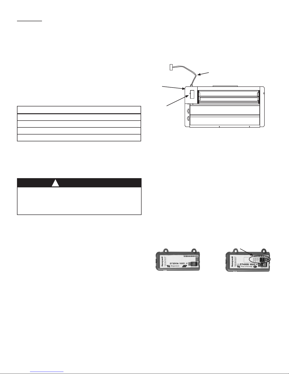
11. Remove the indoor fan motor access panel. (See Fig. 10.)
Wiring
Harness
Actuator
(Hidden)
Outside Air
Temperature
Sensor or
nthalpy Sensor
Fig. 1 - Component Locations —
(Small Economizer Shown)
GENERAL
MicroMetl accessories simplify and minimize procedures on rooftop
applications. Read these instructions completely before beginning.
These installation instructions pertain to the vertical economizer.
1. Turn off unit power supply(s) and install lockout tag.
WARNING
!
ELECTRICAL SHOCK HAZARD
Failure to follow this warning could result in personal injury and/or
death.
Disconnect power supply and install lockout tag before attempting to
install accessory.
2. Remove the existing unit lter access panel. Raise the panel
and swing the bottom outward. The panel is now disengaged
from the track and can be removed. (See Fig. 4.)
3. Remove the indoor coil access panel and discard. (See Fig. 4.)
4. The hood is shipped with the Ultra Low Leak Economizer.
Remove hood from packaging.
NOTE: If the power exhaust accessory is to be installed on the unit,
the hood shipped with the Ultra Low Leak Economizer will not be
used and may be discarded. Save the aluminum lter for use in the
power exhaust hood assembly.
5. Set the Ultra Low Leak Economizer upright.
6. Slide the Ultra Low Leak Economizer assembly into the
rooftop unit. (See Fig. 7). On small and large cabinets be sure
to engage the rear Ultra Low Leak Economizer ange under
the tabs in the return-air opening of the unit base. (See Fig. 8)
7. Secure the Ultra Low Leak Economizer to unit along side and
bottom anges using the screws provided.
8. Remove the tape securing the relief dampers in place.
9. Remove and save the 12-pin jumper plug from the unit wiring
harness (located in the upper left corner of the unit). Insert the
Ultra Low Leak Economizer plug into the unit wiring harness.
Refer to Fig. 9 and 10A for wiring details.
SENSOR & CONTROLS
JADE requires a C7250A for Mixed Air (MA) sensing. The C7250A
temperature sensors are 20k Negative Temperature Coefcient
(NTC). The C7250A MA sensor is required for all applications and
must be mounted in the unit’s mixed air stream (normally the fan
section) either directly to the sheet metal of the fan using selftapping sheet metal screws, or in the air stream using the duct
mounting kit. The C7250A must be wired into the two terminals
on JADE labeled “MAT”. The C7250A sensor must be used in all
applications.
Optional Enthalpy or Dry Bulb Sensor
Both are optional, but at least one must be chosen. The Dry Bulb
Sensor C7250A, or the Enthalpy Sensor C7400S gets wired into
JADE’s S-BUS terminals. Either must be placed under the Outside
Air Hood, or in full exposure to the outside air weather conditions.
Address Dip Switch array
Shipped for OA applications
20k-Ohm Dry Bulb Sensor SylkBus Sensor
NOTE: The protective lm on the dip switch is only necessary
during the factory assembly process. Simply push through the lm
to set the dip switches; this will not harm the device.
Once installed, a sensor can be changed to a different application
by simply changing the DIP switch setting and relocating to the
appropriate location.
2
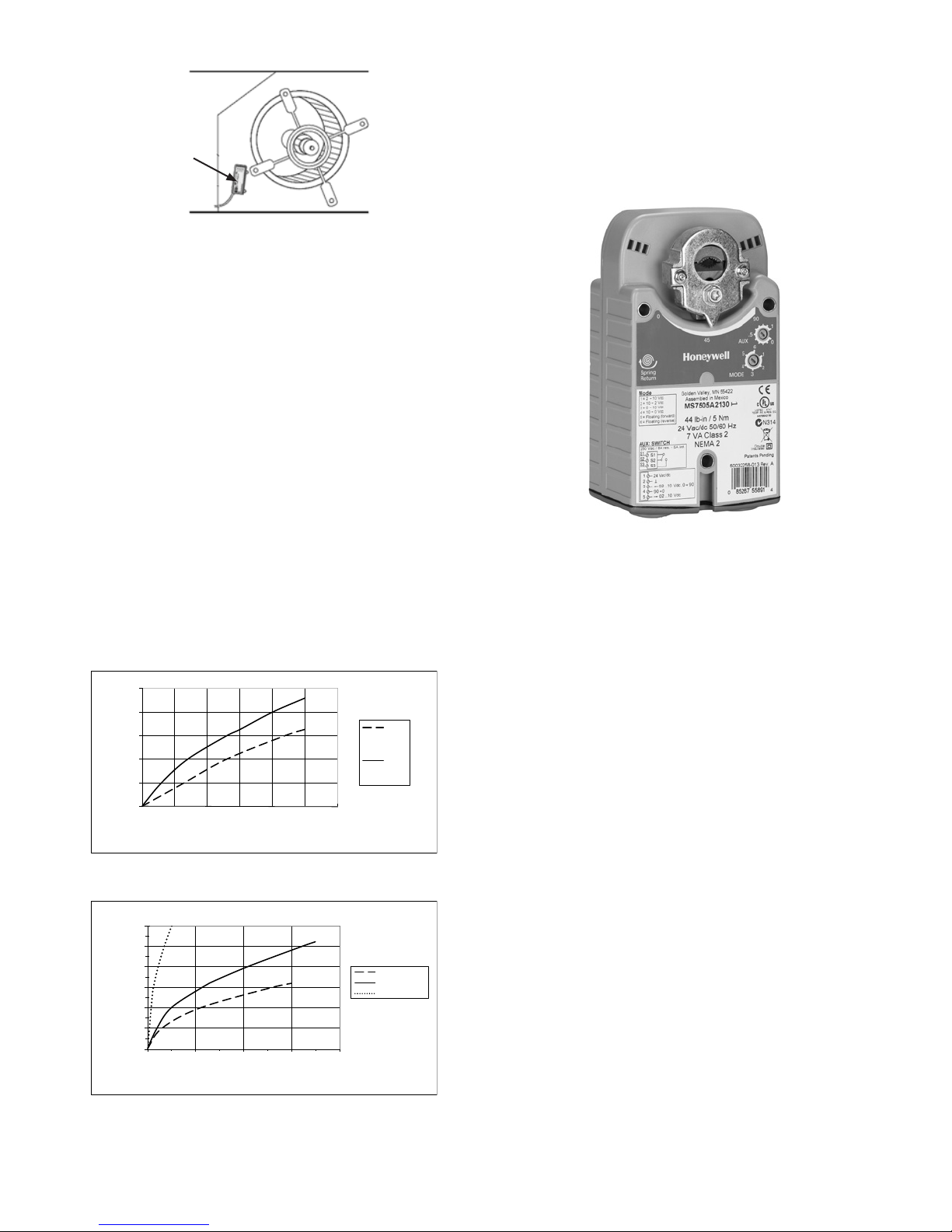
0
500
1000
1500
2000
2500
0 0.05 0.1 0.15 0.2 0.25 0.3
RELIEF FLOW (CFM)
RETURN DUCT STATIC PRE SSURE (i n. wg )
Small
Cabinet
Large and
Extra
Large
Cabinet
0
1000
2000
3000
4000
5000
6000
0 0.1 0.2 0.3 0.4
RETURN AIR FLOW (CFM)
RETURN DUCT STATIC PRE SSURE DROP (in. wg)
Small Cabinet
Large Cabinet
Extra Large Cabinet
Mixed Air
Temperature
Sensor
Mounting
Location
Typical C7250 Sensor Location
Optional CO2 Sensor
Any CO2 Sensor which has a 0-10 Vdc output can be used. We
recommend the MicroMetl 9901-0051 Wall or Internal Duct Mount,
or the MicroMetl 9901-0052 External Duct Mount. CO2 connects
to the IAQ outputs of the JADE Controller.
Optional Smoke Detector
The JADE Controller is designed to allow a shutdown command
from devices similar to a Smoke Detector. A Smoke Detector
connects to the AUX inputs of the JADE Controller. However, if the
JADE Controller is previously programmed to interface with a heat
pump, this function may not be available. The only other option is
to route the power to the JADE through a smoke detector, therefore
removing the power if a re or smoke is detected. Normal default
for power off is often a complete closing of all outside dampers.
Warning: Any circumstance which involves emergency shutdown
should be carefully studied and written into company policy. Please
adhere to all applicable electrical, local, and re emergency codes
before integrating emergency devices into your HVAC scheme.
We recommend the MicroMetl 9901-0091 Smoke Detector.
Optional Power Exhaust
MicroMetl carries a large variety of Power Exhausts. To control the
Power Exhaust output, connect to (Ground) GND and EXH1-0 on
the JADE Controller.
Actuator – Communicating
This Actuator Communicates to the JADE Controller and is
required by some codes. It works with JADE to provide improved
control, eld detection, diagnostics, and save time during setup
and testing. Connects to the S-bus and, ACT COM, and ACT 24+
on the JADE Controller.
STARTUP INSTRUCTIONS
Once the economizer and all electronics are correctly installed and
wired. Apply power to the system and wait sixty minutes before
checking for alarms. This allows time for all the congured devices
(e.g. sensors, actuator) to become operational. The exception is
the MA sensor which will alarm immediately! Upon power up (or
after a power outage or brownout), the W7220 controller module
begins a ve minute power up delay before enabling mechanical
cooling.
Fig. 2 - Barometric Relief Flow Capacity
Fig. 3 - Return Air Pressure Drop
3
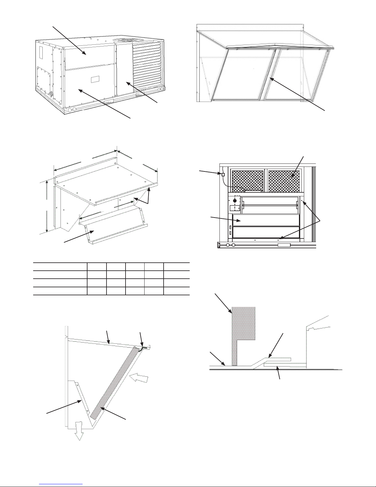
Filter Access Panel
Fig. 4 - Typical Outdoor-Air Section
Outdoor-Air Opening and
Indoor Coil Access Panel
Access Panel Locations
A
B
Compressor
Access Panel
Hood Filter
Divider
Fig. 6A - Hood for Extra Large Cabinet
HVAC Unit Filters
Wiring
Harness
C
Hood Divider
D
Hood Top and
Side Assembly
Fig. 5 - Hood Assembly
ECONOMIZER P/N A B C D SHIP WT.
ECD-SRT12TA-D2 33.37” 17.43” 19.05” 29.5” 55 lb
ECD-SRT34TA-D2 40.37” 22.28” 24.48” 36.27” 80lb
ECD-SRT05TA-D2 52.92” 27.03” 33.41” 49.92” 98lb
NOTE: The ECD-SRT05TA-D2 Series hood has 2 aluminum
lters and a hood lter divider installed between the lters. (See
Fig. 6A.)
Hood Top
Filter Clip
Economizer
Fig. 7 - Ultra Low Leak Economizer Installed in
HVAC Unit
Unit Filter
Rack
Hold Down Tab
Unit Base
Insert
Screw in
Flanges
Hood
Divider
Barometric
Airow
Fig. 6 - Filter Installation
Outside Air
Cleanable
Aluminum Filter
Rear Flange
Fig. 8 - Rear Ultra Low Leak Economizer Flange
Installation (Small and Large Cabinet)
4
Plug 10-pin plug from
12. Locate the mixed (supply) air temperature sensor in the
economizer hardware bag. Mount the sensor in the indoor
fan section of the unit, see Figure 12. Locate the orange
and brown wires in the wire bundle in the indoor fan section.
Connect these orange and brown wires to the 2-wire harness
attached to the Sensor.
Mixed air default setting is 53°F and can be adjusted from 38°F
to 70°F.
13. While everything is open, install and wire any other accessories
and/or sensors as applicable and convenient, per their
installation instructions and/or the Conguration section of this
instruction. Some accessories require that unit ducting already
be installed.
NOTE: If also installing a power exhaust accessory, skip step 14
and follow the power exhaust instructions instead.
14. Install the Ultra Low Leak Economizer hood over the Ultra Low
Leak Economizer. Use screws provided.
15. The W7220 controller is shipped mounted to a bracket. Install
the controller / bracket in the top left corner of the unit control
box as shown in wiring diagram, Fig. 9 and 10A. Screw in
place through pre-punched holes.
16. For 1 and 2 speed units connect the plugs coming from the
controller as shown in wiring diagram, Fig. 9 and 10A.
NOTE: Provided harness will be connected as shown in Fig. 9
and 10A.
17. For 3 speed (48/50LC 07-12) units, the harness attached to
the W7220 controller must be removed, and can be discarded.
Locate harness shipped in plastic bag in the control box of unit.
Attach this harness to the W7220 controller as shown in Fig
10B and 10C.
NOTE: Harness provided with economizer is not used with 3 speed
(48/50LC 07-12) units.
18. Adjust controller settings (minimum position, outside air, etc.)
per instructions detailed later in this instruction.
19. Follow all local and other applicable codes.
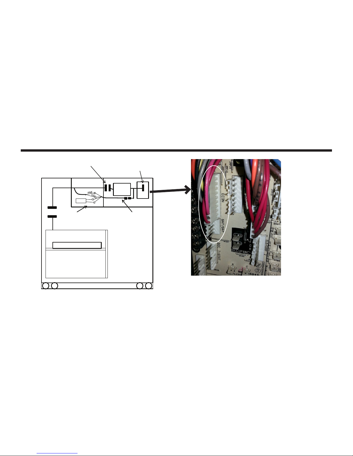
Unplug the 10-pin plug from
PL6 from the Central Terminal
Board (in control box) and plug
into 10-pin plug from W7220
Indoor Blower
Section
SAT
PL6
Connect SAT sensor and Pink
and Violet wires from PL6 to
the 48TMHSRSE—A20
harness.
BRN
ORN
Control box
W7220 into ECONO
terminals on Central
Terminal Board
W7720
48TMHSRSE--A20
harness with 4- pin
plug
Central
Term Brd
See Picture
ECONO
Economizer X
Fig. 9 - Harness Detail
WIRING INSTRUCTIONS FOR SINGLE OR MULTIPLE SPEED
INDOOR FAN
A. Install W7220 (with harnesses attached) in unit control box.
See wiring diagram in instructions.
B. Unplug 10-pin plug shown above in picture, from Central
Terminal Board (CTB).
C. Attach 10-pin plug disconnected from (CTB) to 10- pin plug
harness from W7220 controller.
D. Connect other 10-pin plug from W7220 controller into ECONO
terminals on CTB. See picture above. On the 10-pin take the
red wire with a spade connector and connect it to "R" on the
CTB, take the brown wire with a spade connector and connect
it to "C" on the CTB.
E. Connect 4-pin plug from the W7220 controller to the 4-pin
harness provided with economizer accessory.
F. Route harness back to the indoor blower section of the unit.
G. Mount Supply (or Mixed) Air Temperature sensor, and connect
Brown and Orange wires from harness to the SAT.
H. Connect Pink and Violet wires from harness to the Pink and
Violet wires from PL6 economizer harness
5
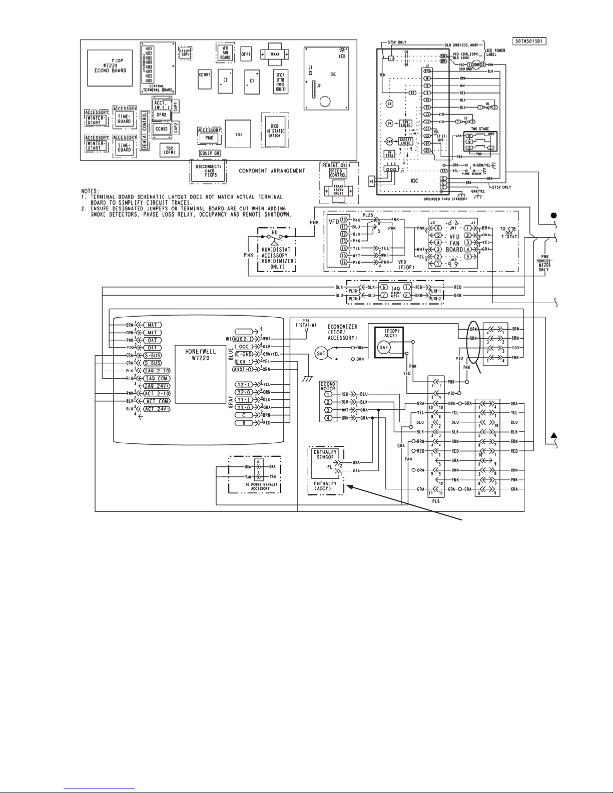
If using the OA enthalpy accessory,
the OAT must be removed. Set sensor
dip-switches, See Table 11.
Fig. 10A - Typical Wiring Diagram For 1 and 2 Speed Units
(2 Speed Diagram Shown)
48TMHSRSE--A20
Harness
6
 Loading...