

Micromega AP-180 Operating Manual
OPERATING MANUAL
AP-180
AUDIS sarl 13-15, rue du 8 Mai 1945, ZA de la Haie Griselle, 94470 Boissy Saint Léger FRANCE
TEL: +33 (0)1 4382 8860 FAX: +33 (0)1 4382 6129 INTERNET: http://www.micromega-hifi.com
TECHNICAL CHARACTERISTICS AP180
AUDIO CHARACTERISTICS
Stereo Analog Inputs.………….………………………………..……................................................................................................................................................................................... 2
Maximum analog input level (RMS)……………...……………………………………………………………………………………………………………………………………….....…....... 2V
Coaxial digital inputs……………….……………………………………………………………………………………………………………………………………...……..…............................ 2
Optical digital inputs…..…………..……………………………………………………………………………………………………………………………..……………...…............................ 2
Digital input format…….……………………………………………………………………………………………………………………………………………………..…...….............. IEC1937
Digital input sampling frequency………………………………………………………………………………………………………………………………….…………….... 32 - 44.1 – 48 kHz
D/A resolution………………………………………………………………………………………………………………………………………..……….…………..…......................... 6 x 20bits
Line-out Audio outputs………………………..…………………………………………………………………………………………………………………………............................................ 6
Output impedance..……………………………………………………………………………………………...…………………………………………………..…………….…………… ! 600"
Front gain (L+R)………………………………….....................................................................................................................................................…...….......................................... 14 dB
Sub gain…….……………………………….…….......................................................................................................................................................................................................... 24dB
Maximum line output level (RMS).…………….………………………………………………………………………………………………………………………….……………………....... 5V
Center channel power (4")……………………………………………………………………………………………………………………………………………………….……............. 180 W
Bandwidth (40W / 8")................…………………………………………………………………………………………………………………………………………………....... 20 Hz - 30 kHz
Surround channels power (4")..….…….…………………………………………………………………………………………………………………………………………..……..... 2x180 W
Output impedance…….………………………………..…….....................................................................................................................................................…………….. ! 0.1 " / 1kHz
THD (20Hz-20kHz) ........………………………………..……………………………………………….………............................................................................................................. ! 0.1 %
Power headroom.….…..…………………………………………............................................................................................................................................................................... # 15dB
Signal to noise ratio (A weighted).....…………….....................................................................................................................................................………………….…….......... # 85 dB
Decoder type….…………………………....................................................................................................................................................……….…… DOLBY Digital Pro Logic II / DTS
Power supply
Power consumption (Max)….…………………………….…….................................................................................................................................................................................. 300 W
Fuse type (5x20)…….………………………………….................................................................................................................................................................. 1.6A / 250V (slow blow)
3.15A / 130V (slow blow)
Dimensions : W x D x H in mm..………………………………………………………..…………………………………………………………………………………………… 430 x 295 x 70
Weight...……………………………………................................................................................................................................................................................................................. 6.5 kg
WARRANTY
This warranty will start from the date of purchase of the Micromega product.
Statutory warranty regulations apply in the country where the Micromega product was purchased. In case of
complaints please contact the dealer who supplied your Micromega product.
WARNING: Warranty will be nulled if the unit is not shipped back in its original packing or if the serial
number has been modified or erased.
Warranty Certificate Dealer's Stamp
Serial number
!
Date of purchase:
Dear customer,
We thank you for having chosen the AP180 processor.
This units combines a very high quality of sound reproduction to a very great ease of use. The reading of this instruction
manual is not useless and will allow you to benefit the best from all the original functions of your AP180.
CHECKING
Check with attention the state of the carton box. If you have the
slightest doubt about it do not hesitate to contact your retailer.
UNPACKING
Remove with the greatest care your AP180 from its box. We
advise you to preserve this last in a dry place. If you must turn
back your unit to your retailer, it would be necessary for you to
return it in its packing of origin because the guarantee applies only
to this only condition.
ACCESSOIRES
When opening the box you should find the following accessories :
AC line cord.
RC Handset
LINE VOLTAGE
- Check that the voltage indicated on the descriptive label on the
back of the unit is matching that which serves your location.
- In the contrary case please contact your approved retailer.
INSTALLATION
In order to benefit the maximum of all the advantages of your
AP180, it is important to install it under good conditions.
We advise you, as far as possible, to install the unit on the shelves
of an audio rack or a piece of furniture in order to avoid any
excessive heating.
!!! IMPORTANT !!!
If you choose, for a question of place or aesthetics, to pile up the
units, it is imperative to place AP180 at the top of the pile. Never
place another unit at the top of AP180; it is advised to leave an
open space of approximately 30 cm to the top of that in order to
ensure a good ventilation to him.
CONNECTIONS
After having checked that the mains voltage of AP180 is identical
to that which serves your location, connect the power cord to the
power inlet of the unit and the wall inlet. Connect the analog
outputs of your Audio-Video sources to the analog inputs of
AP180 AN1 and AN2. These inputs decode the signals coded in
Dolby Pro Logic II.
Connect the digital outputs of your Audio-Video sources to the
digital inputs of AP180 Coax-1, Coax-2, Opto-1, Opto-2. These
inputs decode the compressed data signals. Connect the Stereo
Cinch cord between the outputs FRONT L+R of AP180 to the
inputs of your main amplifier. If you use IA60, IA100 or IA180 as
main amplifier, connect the Stereo cord to input AUX2/PRO of
your amplifier.
If you have an amplified sub-woofer, connect its input to the SUB
output of AP180 and refer to the subwoofer manual for its
implementation.
If you have a centre speaker, connect to it to the speaker output
labelled CENTER of AP180.
Connect the left surround speaker to the speaker output labelled
LEFT SURROUND of AP180 and right surround speaker to the
speaker output labelled RIGHT SURROUND.
The connector marked “RS232” located on the left of the digital
inputs of AP180 is connected to an optional RS232 switching.
SWITCHING ON
After having turned your AP180 ON by operating the On/Off
switch located on the left power inlet at the back of the unit, the
LED Standby lights up. Press on the Standby key. The display
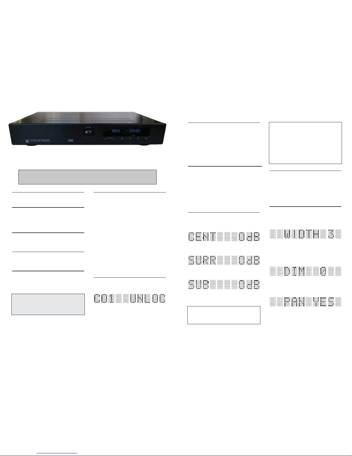
indicates then:
AP180 is ready to be configured.
DECODING SYSTEM INDICATION
AP180 detects the type of entering signal automatically and
opposite indicates it by means of illuminated logos below the dot
matrix display of the unit.
If you send on AP180 a stereo signal, analog or digital, it will be
decoded as a Dolby Pro Logic signal. You can also transform this
signal into Dolby Pro Logic II while pressing on key MODE. The
various modes are:
Dolby Pro Logic, Dolby Pro Logic II Movie, Dolby Pro Logic II
Music., Stereo. To pass from one mode to the other press
successively on MODE key.
DISPLAY OFF
You can choose to minimize the display by pressing the key
Display ! of the remote or by a long pressure on the DISC key of
the unit.
When accessing another function, the display becomes full again for
5 seconds to show the state of the unit.
To come back to normal displaying mode, press Display "on the
remote or do a long pressure of the < INPUT key.
If you use a Micromega IA-XX as main amplifier you will have to put
it in Display OFF mode before turning your AP-180 in Display OFF,
otherwise you main amplifier will stay in normal Display mode.
ADJUSTMENTTS DURING LISTENING
Although the ideal tuning is obtained with the procedure of test, it
is wise to be able to reach certain tunings of level during the
listening of a program.
In the course of listening, you can press on the key MODE.
The display indicates then:
By using the encoder of the apparatus or the keys MAIN -/+ of
the remote control, you can adjust the level of the centre speaker
of $ 10dB. Press again on the key MENU.
The display indicates then:
By using the encoder of the unit or the keys MAIN -/+ of the
remote control, you can adjust the level of the surround speakers
$ 10dB. Press again on the key MENU.
The display indicates then:
In the case or you do not have a sub-woofer, the display will
indicate BASS instead of SUB.
By using the encoder of the unit or the keys MAIN -/+ by the
remote control, you can decrease the low register level of 10dB.
NOTE 1 : The values of tuning of the test procedure are
regarded as values of reference.
This fact AP180 will return systematically to these values
each time you change input or that you will put the unit in
standby mode.
IMPORTANT
In DOLBY DIGITAL mode, it is possible to set AP180
without dynamic compression. This mode is called DYN
DAY in opposition to the mode DYN NIGHT which
allows the film listening the night. Following the small
ADJUSTMENT DURING LISTENING a pressure on the
key MENU and the display indicates DYN NIGHT.
By using the encoder of the unit or the keys MAIN -/+ of
the remote control, it is possible to set AP180 on DYN
DAY which increases substantially the dynamics of the
signal.
DOLBY PRO LOGIC II
The Dolby Pro Logic II system creates 5 channels starting from a
2 channels source. There are two principal modes: The MOVIE
mode and MUSIC mode.
MOVIE Mode is recommended for all the Dolby Pro Logic
encoded programs such as the televised programs and the
programs recorded on VHS and DVD.
MUSIC Mode is mainly dedicated to the reproduction of stereo
musical sources.
DOLBY PRO LOGIC II MUSIC
The Pro Logic II Music mode allows specific tunings to adapt this
mode has your preferences.
When AP180 is set as Music Pro Logic II mode, press on the key
mode. Following the tunings during the listening of the levels
Centre, Surround and Sub (or Low), a pressure on the key MENU
and the display indicates:
By using the encoder of the unit or the keys MAIN -/+ of the
remote control, it is possible to adjust WIDTH between 0 and 7.
When this tuning is to 0 the totality of the signal of the center
speaker is directed towards the center speaker itself. When this
tuning is to 7 the signal of the center speaker is also distributed
between the left and right main speakers.
An additional pressure on the key Mode and the display indicates
then:
This adjustment makes it possible to position sound space
forwards or backwards. The ideal adjustment is 0. While acting on
the encoder or the keys MAIN -/+ of the remote control, one can
move sound space forwards with DIM 1, 2 or 3 or towards the
back and the enclosures of effects with DIM -1, - 2 and -3.
A pressure on the key MENU and the display indicates:
By using the encoder of the unit or the keys MAIN -/+ of the
remote control, it is possible to adjust this functionality on YES or
NO the panorama effect is to be tested and use according to your
personal tastes.
These three adjustments can be used together or separately and
you will acquire experience in time.
 Loading...