

Page 1
Instructions for Use - US
Micromedical
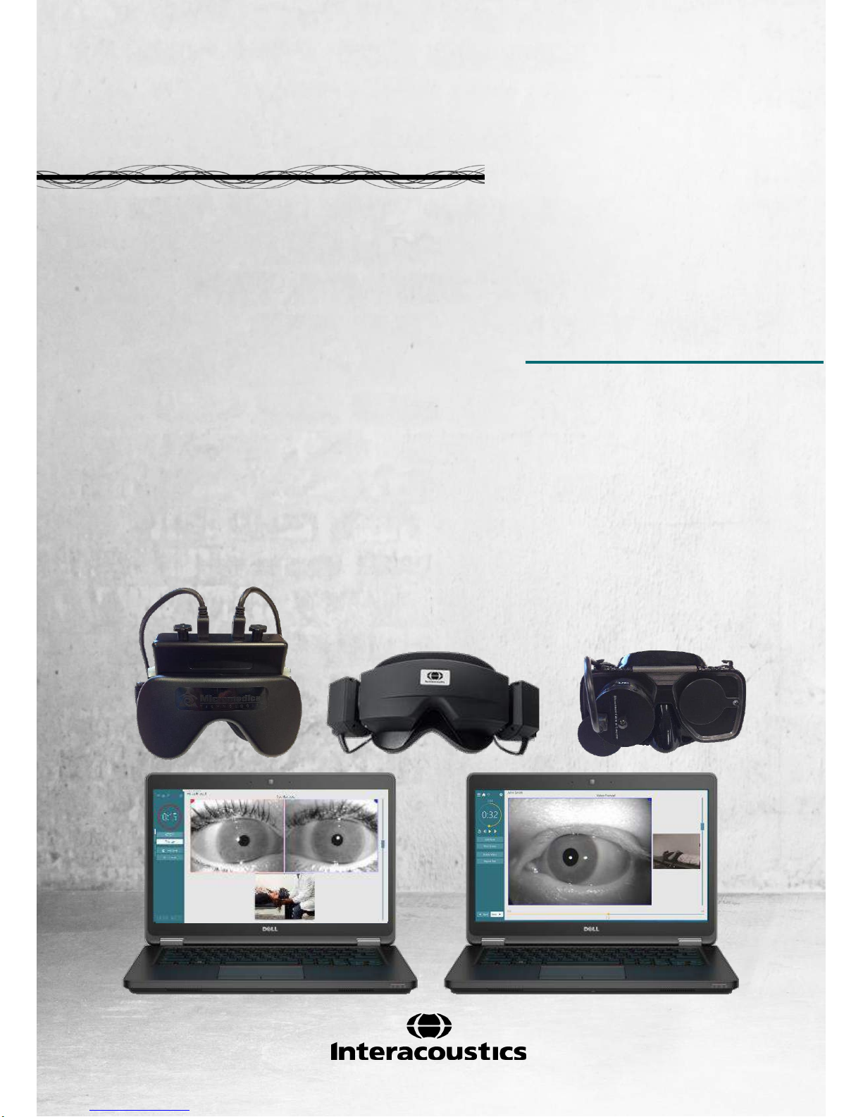
VisualEyesTM 505
by Interacoustics
D-0115288 – C – 2018/02
Page 2

Copyright © by Interacoustics. All rights reserved. Information in this document is subject to change
without notice. Companies, names, and data used in example herein are fictitious unless otherwise
noted. No part of this document may be reproduced or transmitted in any form or by any means,
electronic or mechanical, for any purpose, without express written permission of Interacoustics A/S or
its licensees.
FireWire® is a registered trademark of Apple Inc., registered in the United States and other countries.
Windows® is a registered trademark of the Microsoft Corporation, registered in the United States and
other countries.
Page 3

Table of Contents
1 INTRODUCTION ........................................................................................................................... 1
About this manual ............................................................................................................... 1
Intended use ....................................................................................................................... 1
Product description ............................................................................................................. 1
1.3.1 System configurations .............................................................................................. 1
1.3.2 Minimum requirements to PC ................................................................................... 2
1.3.3 ncluded and optional parts ....................................................................................... 2
Warnings and precautions .................................................................................................. 4
2 UNPACKING AND INSPECTION ................................................................................................. 7
Unpacking and inspection ................................................................................................... 7
Reporting imperfections ...................................................................................................... 7
Marking ............................................................................................................................... 8
3 SETUP AND INSTALLATION ...................................................................................................... 9
Introduction to VisualEyes™ VF 505 software suite ........................................................... 9
Installation of OtoAccess™ database ................................................................................. 9
Installation of VisualEyes™ 505 software ........................................................................... 9
Uninstall software ................................................................................................................ 9
Hardware setup ................................................................................................................. 10
3.5.1 Laptop / PC ............................................................................................................. 10
3.5.2 The VisualEyes™ 505 video fenzel goggles .......................................................... 10
3.5.3 Side mount camera goggles ................................................................................... 10
3.5.4 Top mount camera goggles .................................................................................... 11
3.5.5 Front mount camera goggles .................................................................................. 11
3.5.6 Foot Pedal .............................................................................................................. 11
3.5.7 VisualEyes™ remote control .................................................................................. 12
3.5.8 External room camera ............................................................................................ 12
Connection layout ............................................................................................................. 13
4 PATIENT ENTRY ........................................................................................................................15
Entering patient information .............................................................................................. 15
Licensing ........................................................................................................................... 16
Micromedical VisualEyes™ main screen .......................................................................... 17
4.4 Room recording................................................................................................................. 17
4.5 Patient preparation ............................................................................................................ 17
4.6 Testing the Patient ............................................................................................................ 18
4.6.1 Starting the test ....................................................................................................... 18
4.6.2 Pausing the test ...................................................................................................... 18
4.6.3 Ending the test ........................................................................................................ 18
4.6.4 Additional Functions ............................................................................................... 18
4.7 Session Review and Write Report .................................................................................... 18
4.8 Additional information ....................................................................................................... 18
5 CARE AND MAINTENANCE ......................................................................................................19
General maintenance procedures..................................................................................... 19
How to clean the VisualEyes™ system ............................................................................ 19
Warranty and Service ....................................................................................................... 20
5.3.1 PRODUCT LIFE ..................................................................................................... 20
5.3.2 PRODUCT SERVICE ............................................................................................. 20
5.3.3 PRODUCTS RETURNED FOR REPAIR ............................................................... 21
5.3.4 WARRANTY DETERMINATION ............................................................................ 21
5.3.5 EXTENDED WARRANTY....................................................................................... 21
5.3.6 SERVICE CONTRACT ........................................................................................... 21
5.3.7 NON-WARRANTY FACTORY REPAIRS ............................................................... 21
Page 4

6 GENERAL TECHNICAL SPECIFICATIONS ..............................................................................23
PC Hardware and Software .............................................................................................. 23
Operation and storage specifications ............................................................................... 23
Standards .......................................................................................................................... 23
Component specifications ................................................................................................. 23
Electromagnetic compatibility (EMC) ................................................................................ 25
6.5.1 Electromagnetic compatibility (EMC) for top-mounted goggles ............................. 25
6.5.2 Electromagnetic compatibility (EMC) for side mounted goggles ............................ 27
Page 5

VisualEyes™ 505 Instructions for Use – US Page 1
1 Introduction
About this manual
This manual is valid for the VisualEyes™ 505 Software version 2.1. This product is manufactured by:
Interacoustics A/S
Audiometer Allé 1
5500 Middelfart
Denmark
Tel.: +45 6371 3555
Fax: +45 6371 3522
E-mail: info@interacoustics.com
Web: www.interacoustics.com
Distribution and service:
Micromedical Technologies Inc.
10 Kemp Drive
Chatham, IL 62629
USA
Tel.: 1 (800) 334-4154
Web: www.micromedical.com
Intended use
The VisualEyes™ 505 is a Video Frenzel system which provides information to assist in the evaluation,
diagnosis and documentation of vestibular disorders. Nystagmus of the eye is recorded by use of a goggle
mounted with cameras. These images are displayed and stored in the software.
This information then can be used by a trained medical professional to assist in diagnosing vestibular
disorders. The target population for VisualEyes™ 505 is 5 years of age+.
The VisualEyes™ 505 is to be used by trained personnel only, such as audiologists, Physical therapists,
ENT surgeons, doctors, hearing healthcare professionals or personnel with a similar level of qualifications.
The device should not be used without the necessary knowledge and training to understand its use and how
results should be interpreted.
Federal law restricts the sale, distribution, or use of this device to, by, or on the order of a licensed
medical practitioner
NOTICE
VisualEyes™ 505 testing may be contrainidicated in patients who exhibit the following: blindness, broken
nose or other face/head trauma, recent eye surgery and ptosis.
Product description
VisualEyes™ 505 consists of a goggle with one or two camers that are connected to a computer and
dedicated software. Additional parts may also be included as specified in section 1.3.3.
1.3.1 System configurations
The VisualEyes™ 505 is available in 2 different configurations:
1. VisualEyes™ 505 monocular: One camera, eye images are displayed and stored for later replay.
Option for external situation recording.
2. VisualEyes™ 505 binocular: Two cameras, eye images are displayed and stored for later replay.
Option for external situation recording.
Page 6

VisualEyes™ 505 Instructions for Use – US Page 2
1.3.2 Minimum requirements to PC
Laptop PC: One 34 mm PCExpressCard slot available (for side mount FireWire® camera goggles only).
Desktop PC: One PCIExpress card available. (for side mount FireWire® camera goggles only).
Intel i5 processor 2.5 GHz or better.
Minimum 4 GB RAM or more.
Hard drive with min. 250GB space.
Minimum display of 1366X768 (Higher resolution recommended).
Operating Systems supported:
Windows®7 32-bit or 64-bit.
Windows® 8.1 64-bit.
Windows® 10 64-bit.
1.3.3 Included and optional parts
As standard, VisualEyes™ 505 system is delivered with the following:
USB camera systems
FireWire® camera systems
Included parts
Remote Control or Foot pedal
Instructions for Use
VisualEyes™ 505 installation media
OtoAccess™ Database media
VisualEyes™ 505 Quick Start Guide
Optional parts
based on goggle
type
2D-VOGfw goggle w. side
mounted cameras
USB 2.0 Camera module (two
modules in binocular configuration)
Disposable goggle foam pads – Box
of 24 pcs
1.5 mm hexagon screwdriver for
camera retaining screws
7-port USB 3.0 hub w. external
power supply
USBM2.1A goggle w. front
mounted camera
Adult mask for USB monocular
camera
Camera module with 15’ USB cable
7-port USB 3.0 hub w. external
power supply
USBM2.1P goggle w. front
mounted camera
Pediatric mask for USB monocular
camera
Camera module with 15’ USB cable
A to Mini B
7-port USB 3.0 hub w. external
power supply
2D-VOGfw goggle w. side mounted
cameras
FireWire® camera module (two modules
in binocular configuration)
Disposable goggle foam pads – Box of
24 pcs
PCExpressCard Stabilization kit (laptop
configuration)
PCExpressCard (for laptop
configuration)
PCI ExpressCard (for tower PC
configuration)
4-port USB hub
Page 7

VisualEyes™ 505 Instructions for Use – US Page 3
BG4.0KUSB goggle w. top
mounted cameras
Goggles USB Asian faceplate
binocular
Two 15’ USB cables A to Mini B
7-port USB 3.0 hub w. external
power supply
BG4.0USB goggle w. top mounted
cameras
Goggles USB binocular
Two 15’ USB cables A to Mini B
7-port USB 3.0 hub w. external
power supply
Table 1. VisualEyes™ 505 included and optional parts
Page 8
VisualEyes™ 505 Instructions for Use – US Page 4
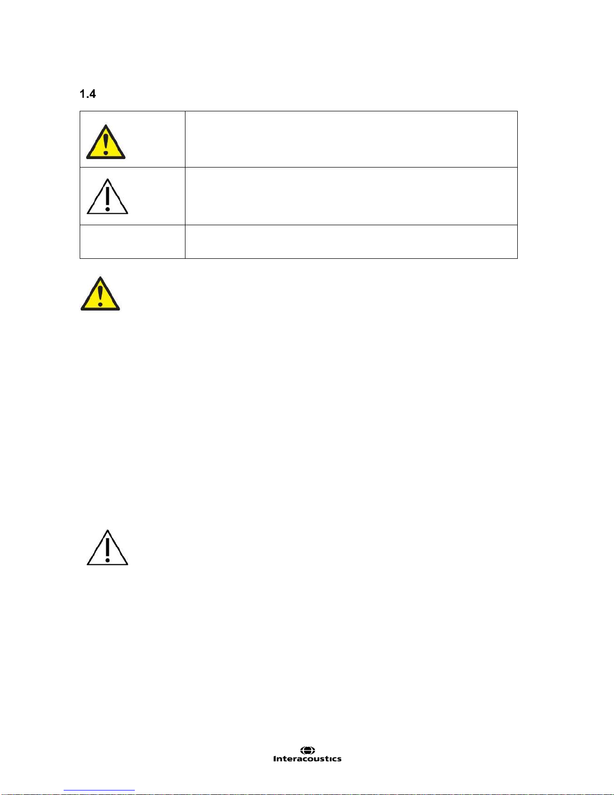
Warnings and precautions
WARNING indicates a hazardous situation which, if not avoided, could result
in death or serious injury.
CAUTION, used with the safety alert symbol, indicates a hazardous situation
which, if not avoided, could result in minor or moderate injury.
NOTICE
NOTICE is used to address practices not related to personal injury.
1. A Separation Device (isolation device) is needed to isolate the equipment located outside the patient
environment from the equipment located inside the patient environment. In particular such a
Separation Device is required when a network connection is made. The requirement for the
Separation Device is defined in IEC 60601-1, edition 3, clause 16.
2. The system must not be used in presence of explosive or flammable gases.
3. The goggle should not be worn by patients with strong defective vision and abnormal rare blink.
Please consult a specialist in such circumstances before using the mask on these types of patients.
4. The system must be switched off before cleaning.
5. Do not use any additional multiple socket-outlet or extension cord.
6. No modification of this equipment is allowed without Interacoustics authorization.
7. The manufacturer will make available on request circuit diagrams, component part lists, descriptions,
calibration instructions, or other information that will assist service personnel to repair those parts of
this system that are designated by the manufacturer as repairable by authorized service personnel.
8. For maximum electrical safety, turn off the power from a mains powered instrument when it is left
unused.
9. The instrument is not protected against harmful ingress of water or other liquids. If any spillage
occurs check the instrument carefully before use or return for service.
10. Do not use the equipment if it is showing visible damage.
1. Use this device only as described in this manual.
2. The system must be serviced at least once a year. The service must verify system functionality.
3. Do not use the equipment if the equipment is broken. Have the equipment serviced.
4. Only personnel with proper training (skilled personnel) should operate the system.
5. Proper use of this device depends on careful reading of this manual and all additional instructions
and labels.
6. Let the system obtain room temperature before turning it on. Extra time for obtaining room.
temperature may be needed to avoid condensation if the system has been moved from a very cold
location to a warmer one.
7. The patients or test persons should not wear any optical utilities such as glasses or contact lenses.
8. The patients or test persons should not wear make up around the eyes.
Page 9

VisualEyes™ 505 Instructions for Use – US Page 5
9. It is recommended that parts which are in direct contact with the patient (e.g. disposable goggle
foam pads) should only be used with one patient, and should therefore be discarded after each
session.
10. Be sure to use only stimulation movements that are acceptable to the patient.
NOTICE
1. To prevent system faults take appropriate precautions to avoid PC viruses and similar.
2. Clean the camera lens and the infrared coated mirrors of the goggle regularly to avoid shadows on
the displayed images.
3. Do not drop and avoid other undue impacts to this device. If the instrument is dropped or otherwise
damaged, return it to the manufacturer for repair and/or calibration. Do not use the instrument if any
damage is suspected.
4. Although the instrument fulfils the relevant EMC requirements precautions should be taken to avoid
unnecessary exposure to electromagnetic fields, e.g. from mobile phones etc. If the device is used
adjacent to other equipment it must be observed that no mutual disturbance appears.
Within the European Union it is illegal to dispose electric and electronic waste as
unsorted municipal waste. Electric and electronic waste may contain hazardous
substances and therefore has to be collected separately. Such products will be marked
with the crossed-out wheeled bin shown below. The cooperation of the user is
important in order to ensure a high level of reuse and recycling of electric and
electronic waste. Failing to recycle such waste products in an appropriate way may
endanger the environment and consequently the health of human beings.
Page 10

VisualEyes™ 505 Instructions for Use – US Page 6
Page 11

VisualEyes™ 505 Instructions for Use - US Page 7
2 Unpacking and inspection
Unpacking and inspection
Check box and contents for damage
When the instrument is received, please check the shipping box for rough handling and damage. If the box is
damaged it should be kept until the contents of the shipment have been checked mechanically and
electrically. If the instrument is faulty, please contact your local distributor. Keep the shipping material for the
carrier’s inspection and insurance claim.
Keep carton for future shipment
VisualEyes™ 505 comes in its own shipping carton, which is specially designed. Please keep this carton. It
will be needed if the instrument has to be returned for service. If service is required, please contact your
local distributor.
Reporting imperfections
Inspect before connection
Prior to connecting the product it should once more be inspected for damage. All of the cabinet and the
accessories should be checked visually for scratches and missing parts.
Report immediately any faults
Any missing part or malfunction should be reported immediately to the supplier of the instrument together with
the invoice, serial number, and a detailed report of the problem. In the back of this manual, you will find a
‘Return Report’ where you can describe the problem.
Products returned for repair
If the manufacturer requests that you return the product for evaluation or repair, pack the product well,
preferably in the original shipping container with a Return Material Authorization (RMA) number provided by
the manufacturer. Systems with optional rotational chairs will be serviced on-site by the local distributor.
Page 12

VisualEyes™ 505 Instructions for Use - US Page 8
Marking
The following marking can be found on the instrument:
Symbol
Explanation
Type BF applied parts.
Type B applied parts.
Follow instructions for use.
WEEE (EU-directive).
This symbol indicates that when the end-user wishes to discard this product,
it must be sent to separate collection facilities for recovery and recycling.
Failing to do so may endanger the environment.
0123
The CE-mark indicates that the manufacturer meets the requirements of
Annex II of the Medical Device Directive 93/42/EEC for the quality system.
Year of Manufacturer.
Manufacturer
Do not re-use.
Parts like foam cushions and similar are for single use only.
Reference number used to denote the model of the equipment.
Legend of Symbols.
Page 13

VisualEyes™ 505 Instructions for Use - US Page 9
3 Setup and installation
Introduction to VisualEyes™ VF 505 software suite
The VisualEyes™ 505 combines leading edge technology with touch screen capability in a new streamline
software interface. The VisualEyes™ 505 provides information to assist in the evaluation, diagnosis and
documentation of vestibular disorders. Eye movements are recorded by use of a goggle mounted with one or
two infrared video cameras. The eye images are displayed in real time in large format on a computer
monitor. External environments (room) are recorded by use of an integrated / external USB camera if
desired. Patient interview is recorded separately for recording patient’s medical history. This information can
then be used by a trained medical professional to assess vestibular disorders.
Installation of OtoAccess™ database
The VisualEyes™ 505 software is accesssed through the Interacoustics OtoAccess™database. The
Interacoustics OtoAccess™ database is used for storage of patient information and data recordings.
Your computer/ laptop will have OtoAccess and VisualEyes™ software pre-installed.
If you find that it is not already installed, or if a re-install is required please read the instructions for use to
included with the OtoAccess™ installation media (CD or Flash drive) or contact your distributor.
Installation of VisualEyes™ 505 software
NOTICE
The OtoAccess™ database must be installed prior to installing VisualEyes™ software.
The VisualEyes™ software will be pre-installed on the computer purchased from the Interacoustics or
Micromedical. In the event when the software must be re-installed, please follow these instructions.
1. Insert the VisualEyes™ Installation CD or thumb drive into the computer.
2. If the installation procedure does not start automatically, click Start, then go to My Computer and
double click the DVD/CD-RW drive or Flash Drive to view the contents of the installation media.
3. Double click the Micromedical VisualEyes™ Installer file to initiate the installation.
4. The VisualEyes™ Setup Wizard will start.
5. Check the box to accept the terms and click Install.
6. After the installation completes, exit the installer.
7. Remove the installation media from the drive and store in a convenient place.
The VisualEyes™ 505 installation will configure OtoAccess™ for VisualEyes™ 505 testing. To use the
VisualEyes™ 505 software, select the Micromedical VisualEyes™ instrument from OtoAccess.
Uninstall software
In Windows® 7 and 8.1, the VisualEyes™ software can be removed from Programs and Features.
1. Open Windows® Control Panel and then select Programs and Features. If the Category option is
used, then under Programs choose Uninstall a program.
2. Select the Micromedical VisualEyes™ entry. Click on Uninstall.
3. In the installer package, choose Uninstall. Once the program is uninstalled, close the installer and
Control Panel.
In Windows® 10, the VisualEyes™ software can be removed from Settings.
1. From the start menu choose Settings.
2. Choose System, then select Apps & features.
3. In the sort box, choose Sort by name.
4. Select the Micromedical VisualEyes™ program in the list, then click on Uninstall.
5. Confirm the process by clicking on the Uninstall button.
In the installer package, choose Uninstall. Once the program is uninstalled, close the installer and
Settings.
Page 14

VisualEyes™ 505 Instructions for Use - US Page 10
Hardware setup
The VisualEyes™ 505 is composed of several selected pieces of equipment. The software is designed to
be compatible with both Interacoustics a/s and Micromedical Technologies Inc. equipment.
Each piece of equipment, its function and installation is described below.
3.5.1 Laptop / PC
The VisualEyes™ 505 suite comes preloaded on a dedicated laptop or pc.
Figure 3.5.1 VisualEyes™ Laptop
3.5.2 The VisualEyes™ 505 video fenzel goggles
The Video Frenzel goggles allow for the recording of eye movements during various test conditions. In
order to achieve this the goggle holds FireWire®/ USB cameras that are used to record the eye images.
The FireWire® / USB cameras use infrared light (IR), which is not visible to the naked eye. The IR
illumination enables sessions to be performed in complete darkness.
3.5.3 Side mount camera goggles
The USB or FireWire® cameras are fixed on the sides of the goggle.
Figure 3.5.2 Side mount camera goggles
The goggles come with replaceable foam cushions that are easily removed between patients by simply
pulling the used foam cushion off of the Velcro pads on the inside of the mask and then aligning a new
foam cushion on top of the Velcro.
The front cover plate of the Combi mask is magnetically fixed and can easily be removed for visual
stimulation tests (i.e. oculomotor). The mask has an adjustable Velcro head strap that secures the
goggles while still providing patient comfort.
Monocular configuration with the side mount camera goggles will have a camera module on one side, and
the other side will be an empty camera module without adjustment knobs.
Page 15

VisualEyes™ 505 Instructions for Use - US Page 11
3.5.4 Top mount camera goggles
The top mount camera goggles block out ambient light with the removable cover over the portal for visiondenied testing. Side-lights on the goggle provide guidance/ illumination when placing the cover on the
goggles. On the left side of the goggles is a switch to start and stop tests. The goggles have an
adjustable Velcro head-strap that secures the goggles while still providing patient comfort.
Figure 3.5.3 Top mount camera goggles
3.5.5 Front mount camera goggles
The front mount camera goggles use a single USB camera pressed into the camera portal on the front of
the goggles mask. The camera can be pressed into either camera portal to record the desired eye. The
USB cable is secured in the cable clip above the portal. Each portal has a swivel cover plate to provide
vision-denied testing. The goggles have an adjustable head-strap that secures the goggles while still
providing patient comfort.
Figure 3.5.4 Front mount camera goggles
3.5.6 Foot Pedal
The foot pedal allows you to begin the measurement testing by pressing the foot switch so you have both
hands free to look after the patient (e.g. Dix Hallpike). Connection with the PC is via a USB port.
Figure 3.5.5 VisualEyes™ Foot pedal
Page 16

VisualEyes™ 505 Instructions for Use - US Page 12
3.5.7 VisualEyes™ remote control
The remote control provides a hand held option for controlling and performing tests within the
VisualEyes™ suite. The operator can operate the software using the remote control while remaining at
the patient’s side during testing. The remote control’s receiver connects to the PC via a USB port, while
the remote control connects to the receiver using 2.4 GHz rf transmission.
Figure 3.5.6 VisualEyes™ Remote Control
1. Top button:
Centers eyes (top mount goggles only)
2. Right button:
Goes forward in the software
If the test is running, it stops the test
If in playback mode, the button will advance to the next test in the list
3. Left button:
Stops the test
4. Bottom button:
Turns on/off the fixation light during a test
3.5.8 External room camera
Figure 3.5.7 USB room camera
The room camera is an external device connected to the computer’s USB port. It serves to record the
external environment and patient testing process from the beginning. The external room camera provides
additional flexibility in recording the testing procedure, though the laptop’s integrated observation camera
can be used with orienting the computer towards the patient.
Page 17

VisualEyes™ 505 Instructions for Use - US Page 13
Connection layout
Figure 3.6.1 Tower PC connection diagram
Figure 3.6.2 Laptop PC connection diagram
NOTICE
Always connect other IT-equipment before powering up the computer.
Power on all connected IT-equipment before starting the VisualEyes™ software.
Always power off the FireWire® card before removing the card from the PC.
Page 18

VisualEyes™ 505 Instructions for Use - US Page 14
(Valid for all configurations).
This equipment is intended to be connected to other equipment thus forming a Medical Electrical System.
External equipment intended for connection to signal input, signal output or other connectors must comply
with the relevant product standard e.g. IEC 60950-1 for IT equipment and the IEC 60601-series for medical
electrical equipment. In addition, all such combinations – Medical Electrical Systems – must comply with the
safety requirements stated in the general standard IEC 60601-1, (edition 3.1), clause 16. Any equipment not
complying with the leakage current requirements in IEC 60601-1 must be kept outside the patient
environment i.e. at least 1.5m from the patient support or must be supplied via a separation transformer to
reduce the leakage currents. Any person who connects external equipment to signal input, signal output or
other connectors has formed a Medical Electrical System and is therefore responsible for the system to
comply with these requirements. If in doubt, contact a qualified medical technician or your local
representative. When the instrument is connected to a PC, or other similar items, beware of not touching the
PC and patient simultaneously.
A Separation Device (isolation device) is needed to isolate the equipment located outside the patient
environment from the equipment located inside the patient environment. In particular such a Separation
Device is required when a network connection is made. The requirement for the Separation Device is defined
in IEC 60601-1 clause 16.
Page 19

VisualEyes™ 505 Instructions for Use - US Page 15
4 Patient entry
Entering patient information
1. Open OtoAccess™ (Figure 4.1.1).
2. If the patient has already been entered, then select the patient in the table; it will highlight blue to
indicate selection.
3. If the patient is not yet listed:
press the New client button
fill in at least the mandatory fields which are marked with a red square (squares are
displayed after the New Client button is pressed)
save the patient details by pressing the Save client button
Figure 4.1.1 OtoAccess™ main screen
4. Double click Micromedical VisualEyes™ in the Select Instrument box. (Figure 4.1.2).
Figure 4.1.2 Micromedical VisualEyes™ instrument
Page 20

VisualEyes™ 505 Instructions for Use - US Page 16
NOTICE
For further instructions about working with the OtoAccess™ database, please see the operation manual for
OtoAccess™.
Licensing
The VisualEyes™ 505 system is licensed and will require specific license key or keys to be put into the
software upon its initial launch to make the Video Frenzel available.
The VisualEyes™ licenses are not time limited, and the same license can be installed on more than one
computer, allowing you to move the cameras between two or more workstations.
NOTICE
The computer set up from the factory will already have the camera serial numbers and license keys
registered in the software.
Prior to starting the VisualEyes™ software suite, make sure that the cameras are connected to the
computer and turned on
The software will automatically detect the cameras and display a Setup License screen (Figure
4.2.11)
For each camera an empty field allows the entry of a new license key
Beside each license key field is an ignore button. If the serial number should be ignored, click on the
ignore button beside it. If there is no camera detected, the ignore button is automatically selected
License keys are not case sensitive. License/s must be entered for the camera/s to use the camera
hardware
Once entered, click Save to store the new license
Figure 4.2.1 Setup License screen
Page 21

VisualEyes™ 505 Instructions for Use - US Page 17
Micromedical VisualEyes™ main screen
When the Micromedical VisualEyes™ software is launched, the main screen will appear. Patient information
is retrieved from the OtoAccess database and is displayed on the main screen (highlighted in Figure 4.3.1).
The patient name will be displayed in all test screens.
Figure 4.3.1 Micromedical VisualEyes™ main screen with patient information circled
4.4 Room recording
A patient interview video recording can be created from the Main screen. Recording can be started and
stopped an unlimited number of times during a patient session. The video will be saved once BEGIN
TESTING has been selected or the user leaves the main screen.
4.5 Patient preparation
The patient should remove any eye makeup prior to testing. Soft contact lenses may be worn with the
goggles, but eyeglasses must be removed. Sanitize the goggles prior to testing each patient. It is
recommended that the testing room be darkened for all vision-denied tests.
Remove the vision-denied cover to allow vision during goggles placement. Place the goggles on the
patient’s face and adjust the strap for a snug fit. For vision-denied testing, place the cover back on the
goggles. Confirm with the patient that there is no light leakage. If the patient still sees light, adjust the
goggles position and tightness of the strap as needed.
Page 22

VisualEyes™ 505 Instructions for Use - US Page 18
4.6 Testing the Patient
4.6.1 Starting the test
Tests can be started in one of three ways:
Tap on the START button on the test screen. This option is available for all tests.
Press the foot pedal or ENTER button on the RF remote. This option is ideal for starting tests when
not at the computer. This option is also available for all tests.
Press the switch on the side of the top-mounted camera goggles. The switch is ideal for starting
tests when positioned next to the patient, such as Dix-Hallpike and Positional tests.
4.6.2 Pausing the test
During the recording of the test, the test can be paused by using the Pause button or pressing the RF
Remote, side switch, or foot pedal. The test can be resumed with the Unpause button or pressing the RF
Remote, side switch, or foot pedal.
4.6.3 Ending the test
To end the test, click or touch the Stop button.
4.6.4 Additional Functions
During the test procedure click or touch the Add Note button to add a comment during the test. The fixation
light inside the video goggles can be turned on and off using the Fixation Light button or using the Fixation
button on the RF Remote. If the test needs to be restarted, press the ESC key on the RF remote or the
escape key on the keyboard.
4.7 Session Review and Write Report
Once all of the tests have been completed, the software will show the Session Review screen. By clicking
or touching Write Report, the user can create a report for the video frenzel tests performed and any findings
seen during testing. When the report is printed, the written report and any notes taken during the tests will
be printed.
4.8 Additional information
For more information about the VisualEyes™ software, please consult the Additional Information manual that
can be accessed from the Help menu within the software.
Page 23

VisualEyes™ 505 Instruction for Use - US Page 19
5 Care and maintenance
General maintenance procedures
1. Camera lenses and IR coated mirrors must be checked regularly for stains and dust, and
should be cleaned with lens cleaning cloth.
2. Goggles cushions for the side mount cameras are single use only and must be
exchanged between patients. This is necessary to avoid the possibility of cross infection.
3. Goggles frame should be cleaned with a Sani-ClothTM disinfectant wipe.
4. Side mount camera goggle straps can be machine washed at 40°C using normal washing
detergents. Do not tumble dry. Please note that the elastic qualities may deteriorate after
more than 10 washing cycles, after which the straps should be replaced.
How to clean the VisualEyes™ system
If the surface of the instrument or parts of it are contaminated, it can be cleaned using Sani-Cloth™
disinfectant wipes. Goggles mirrors and computer touch screens should be cleaned using the provided
lens cleaning cloth to remove dust and fingerprint smudges.
Before cleaning always switch off and disconnect from power
Use a soft Sani-ClothTM to clean all exposed surfaces
Do not allow liquid to enter into the components of the VisualEyes™ system
Do not autoclave, sterilize or immerse the instrument or accessory in any fluid
Do not use hard or pointed objects to clean any part of the instrument or accessory
Recommended cleaning and disinfection solutions:
Sani-ClothTM disinfectant wipes
Procedure:
Clean the touch screen on PC with the lens cleaning cloth when the computer and monitor are
turned off
If the touch screen needs further cleaning, use a Sani-ClothTM disinfectant wipe to clean the
surface. Allow the cleaning solution to completely dry before turning on the computer and
monitor.
Page 24

VisualEyes™ 505 Instruction for Use - US Page 20
Warranty and Service
Micromedical Technologies, Inc. (“Micromedical”) warrants the products it manufactures to be free from
defects caused by faulty materials or poor workmanship for a period of twelve months from date of
shipment from Micromedical. This warranty applies only to the original purchaser and is not transferable.
Micromedical's liability is limited to replacing or repairing, at its option, any of its products that are
returned during the warranty period. Micromedical's liabilities on any claim for loss or damage arising out
of the sale, resale or use of any of its products shall in no event exceed the selling price of the unit.
Computer hardware, application software or operating system software purchased from other vendors is
not warranted, supported or repaired by Micromedical. This warranty excludes normal component wear
and tear.
Micromedical Technologies computerized systems are considered to be medical equipment and are
warranted as such. Installation of any non-Micromedical software by user shall render this warranty null
and void unless such installation has been approved in advance in writing by Micromedical Technologies.
This disclaimer shall also apply if the computer is used or found to have been used for general Internet
access or as an E-mail client. Furthermore, the warranty shall be declared null and void if it is determined
that the operating system has been affected by a software virus or similar corruption of the supplied
hardware or software.
5.3.1 PRODUCT LIFE
Micromedical products utilize hardware and software technology that changes rapidly. Micromedical will
support new products and make every effort to repair or replace with same or similar components for a
period of seven years from date of original purchase. This policy does not apply to refurbished
components or systems. If repaired or replacement components are no longer available, then upgrades
may be possible but are not guaranteed to be available.
5.3.2 PRODUCT SERVICE
Domestic
If a problem occurs with equipment purchased from Micromedical, whether it is software or hardware
related, the buyer should first contact the distributor who installed the equipment. If directed by the
distributor, the customer can contact Micromedical Technical Support directly online at
www.micromedical.com or by telephone (217-483-2122) to isolate and identify the problem. If
Micromedical Technical Support determines a system component is defective, then (1) the defective
component or part should be return shipped to Micromedical for repair, or (2) at Micromedical’s discretion
a replacement component will be sent to and installed by the distributor or customer.
If Micromedical requests that you return the product for evaluation or repair, pack the product well,
preferably in the original shipping container, addressed to: Micromedical Technologies, 10 Kemp Drive,
Chatham, IL 62629 with the RMA number given by Micromedical. Insure the product with the shipper and
choose the shipping method (ground, 2nd day air, next day air) to meet your required schedule. The
customer will be responsible for paying shipping charges to Micromedical, as well as any repairs that
result from shipping damage due to packaging problems. Packaging materials can be requested from
Micromedical if needed for a nominal fee.
International
If a problem occurs with equipment purchased from Micromedical, whether it is software or hardware
related, the buyer should first contact the distributor who installed the equipment. If directed by the
distributor, the customer can contact Micromedical Technical Support directly online at
www.micromedical.com or by telephone (217-483-2122) to isolate and identify the problem. If
Micromedical Technical Support determines a system component is defective, then (1) the defective
component or part should be return shipped to Micromedical for repair, or (2) at Micromedical’s discretion
a replacement component will be sent to and installed by the distributor or customer.
Page 25

VisualEyes™ 505 Instruction for Use - US Page 21
If Micromedical requests that you return the product for evaluation or repair, pack the product well,
preferably in the original shipping container, addressed to: Micromedical Technologies, 10 Kemp Drive,
Chatham, IL 62629 with the RMA number given by Micromedical. Insure the product with the shipper and
choose the shipping method to meet your required schedule. The customer will be responsible for paying
shipping charges to Micromedical, as well as any repairs that result from shipping damage due to
packaging problems.
5.3.3 PRODUCTS RETURNED FOR REPAIR
When returning product, whether in warranty or out of warranty, approval must first be obtained from
Micromedical in the form of a Return Material Authorization (RMA) number. Credit will not be given, nor
repairs made for products returned without such approval or if packaging is not labeled in accordance
with RMA instructions. When approved for return to Micromedical, products must be returned freight and
insurance prepaid by the customer.
5.3.4 WARRANTY DETERMINATION
If upon Micromedical's examination of the product, a warranted defect exists, then the product(s) will be
repaired or replaced and return shipped via ground service at no charge to the buyer. Warranty repairs do
not extend the original warranty period. If the product is out of warranty or if the products have been
subjected to misuse, accident or improper installation or application, or have been repaired or altered by
others without written consent by Micromedical, then non-warranty repair charges apply.
5.3.5 EXTENDED WARRANTY
An extended warranty can be purchased before the original warranty expires to extend the warranty an
additional 12 months. Extended Warranty agreements include telephone consultation and component
exchange or if necessary on-site repair. An extended warranty is available for VisualEyes™, irrigators,
and rotational chair systems.
5.3.6 SERVICE CONTRACT
A Service Agreement for a period of one year may be purchased by the customer for rotational chair
systems. This Service Contract includes telephone consultation, component exchange or if necessary
on-site repair, and one on-site preventive maintenance visit to be agreed upon by the customer and
Micromedical and its representatives.
5.3.7 NON-WARRANTY FACTORY REPAIRS
After Micromedical has run diagnostics on the component or system, the buyer shall be notified of the
repair cost. At such time the buyer must issue a written purchase order to cover the cost of the repair plus
return freight, or authorize the product(s) to be shipped back, as is, at the buyer's expense. Failure to
provide a purchase order within (30) days of notification will result in the product(s) being returned, as is,
at the buyer's expense. Labor and replacement parts are warranted for (90) days from date of repair.
Micromedical Technologies’ policies and charges are subject to change without notice.
Page 26

VisualEyes™ 505 Instruction for Use - US Page 22
Page 27

VisualEyes™ 505 Instructions for Use - US Page 23
6 General technical specifications
PC Hardware and Software
Laptop: 34mm PCExpressCard slot (for side mount FireWire® goggles only).
Desktop: 1 free PCI Express slot (for side mount FireWire® goggles only).
Intel i5 processor 2.5 GHz or better.
Minimum 4 GB RAM or more.
Hard drive with min. 250GB space.
Minimum display of 1366X768 (Higher resolution recommended).
Operating systems supported:
Windows® 7 32-bit and 64-bit.
Windows® 8.1 64-bit.
Windows® 10 64-bit.
Power supply: Use only UE15WCP1 for side mount FireWire® VNG goggle with Laptop computer.
Operation and storage specifications
Operation environment: Temperature: 15 – 35 C
Relative Humidity: 30 – 90%
Transport & Storage: Storage Temperature: 0 – 50C
Transport Temperature: -20 – 50 C
Rel. Humidity: 10 – 95%
Systems can operate on 100 to 240 VAC at frequencies of 50/60Hz.. Only power cables supplied should
be used with the equipment.
Standards
EN 60601-1: 2012
Medical electrical equipment – Part 1: General requirements for basic safety and
essential performance
EN 60601-1-2: 2014
Medical electrical equipment – Part 1-2: General requirements for basic safety
and essential performance – Collateral standard: Electromagnetic compatibility –
Requirements and tests
IEC 60825-1 or
IEC 62471
Safety of laser products
Photobiological safety of lamps and lamp systems
ANSI S3.45.
Performance standard
Component specifications
Component Specifications Top mount VNG goggle
Binocular video eye tracking goggles.
Removable eye cover for vision enabled or vision denied recording.
USB 2.0, 4.5m dual cables to PC.
Resolution: 320 x 240 Pixels @ 100 Hz.
Images: 100 images per second.
Dimensions (L x W x H) 165 x 165 x 89mm.
Horizontal and Vertical Eye movement measurement resolution: approx. 0.33 degrees.
Single IR LED infrared illumination: 950 nm at 1.5 mw/cm2.
Page 28

VisualEyes™ 505 Instructions for Use - US Page 24
Goggle Weight:
Binocular VNG cameras
345g (occluded view) without cables.
Component Specifications Front mount VNG goggle
Monnocular video eye tracking goggles.
Swivel eye portal cover for vision enabled or vision denied recording.
USB 2.0, 4.5m cable to PC.
Resolution: 640 x 480 Pixels @ 30 Hz.
Images: 30 images per second.
Dimensions (L x W x H) 165 x 165 x 89mm.
Horizontal and Vertical Eye movement measurement resolution: approx. 0.25 degrees.
Dual IR LED infrared illumination: 950 nm at 1 mW/cm2.
Goggle Weight:
Binocular VNG cameras
254g without cable.
Component Specifications Side mount VNG goggle
Monocular/ Binocular video eye tracking goggles.
Removable eye cover for vision enabled or vision denied recording.
USB2.0 IEEE1394 FireWire®.
Resolution: 640 x 240 Pixels @ 100 Hz.
Images: 100 or 105 images per second.
Dimensions (L x W x H):302 x 216 x 131mm.
Goggle Weight:
Monocular VNG Camera
240g (non-occluded view).
320g (occluded view).
Binocular VNG cameras
305g (non-occluded view).
385g (occluded view).
Dispensing box with 24 pcs of disposable goggle foam pads.
Isolation transformer:
Standard: IEC60601-1
Power: Please ensure the isolation transformer is rated for at least the total power of the supplied
equipment e.g. LCD screen, video projector, computer, LCD monitor, printer etc.
Page 29

VisualEyes™ 505 Instructions for Use - US Page 25
Electromagnetic compatibility (EMC)
6.5.1 Electromagnetic compatibility (EMC) for top-mounted goggles
The VNG was tested to IEC60601-1-2 standards regarding EMC. This allows you to install and use the
VNG in classic environments, but it does not allow you to use it in harsh environments like operating
rooms where there are many devices producing electromagnetic fields.
Medical electrical equipment needs special precautions regarding electromagnetic compatibility (EMC)
and needs to be installed and put into service according to the EMC information provided.
Caution
Portable RF communications equipment (including peripherals such as antenna cables and external
antennas) should be used no closed than 30 cm (12 inches) to any part of the VNG including cables
specified by the manufacturer. Otherwise, degradation of the performance of this equipment could
result.
The VNG was tested for EMC compliance as a Group 1, Class B device.
Caution
Use of accessories, transducers, and cables other than those specified or provided by the
manufacturer of this equipment could result in increased electromagnetic emissions or decreased
electromagnetic immunity of this equipment and result in improper operation. Contact Micromedical for
approved replacement parts.
Important
The emissions characteristics of this equipment make it suitable for use in industrial areas and
hospitals (CISPR 11 class A). If it is used in a residential environment (for which CISPR 11 class B is
normally required) this equipment might not offer adequate protection to radio-frequency
communication services. The user might need to take mitigation measures, such as relocating or reorienting the equipment.
Guidance and Manufacturer’s declaration – Electromagnetic Emissions
The VNG is intended for use in the electromagnetic environment specified below. The customer or the
user of the VNG should assure that it is used in such an environment.
Emissions Test
Compliance
Electromagnetic environment - guidance
RF emissions CISPR 11
Group 1
The VNG uses RF energy only for its internal
functions. Therefore, its RF emissions are very
low and are not likely to cause any interference
in nearby electronic equipment.
RF emissions CISPR 11
Class B
The VNG is suitable for use in all
establishments, including domestic
establishments and those directly connected to
the public low voltage power supply network that
supplies buildings used for domestic purposes.
Harmonic emissions
IEC 61000-3-2
Class B
Voltage fluctuations/ flicker
emissions
IEC 61000-3-3
complies
Page 30

VisualEyes™ 505 Instructions for Use - US Page 26
Guidance and Manufacturer’s declaration – Electromagnetic Immunity
The VNG is intended for use in the electromagnetic environment specified below. The customer or the
user of the VNG should assure that it is used in such an environment.
Immunity Test
IEC 60601 test level
Compliance Level
Electromagnetic
environment –
guidance
Electrostatic
discharge immunity
(ESD)
IEC 61000-4-2
+/- 6 kV contact
+/- 8 kV air
+/- 6 kV contact
+/- 8 kV air
Floors should be wood,
concrete or ceramic tile.
If floors are covered
with synthetic material,
the relative humidity
should be at least 30%.
Radiated RF
Immunity
IEC 61000-4-3
Stress 4.5 V/M
Stress 4.5 V/M
Not Applicable
Electrical fast
transient/burst
IEC 61000-4-4
+/- 2 kV for power supply
lines
+/- 1 kV for input/output
lines
+/- 2 kV for power
supply lines.
No input/output lines
Mains power quality
should be that of a
typical commercial or
hospital environment.
Surge immunity
IEC 61000-4-5
+/- 1 kV line(s) to line(s)
+/- 2 kV line(s) to earth
+/- 1 kV line(s) to line(s)
+/- 2 kV line(s) to earth
Mains power quality
should be that of a
typical commercial or
hospital environment.
Conducted RF
Immunity
IEC 61000-4-6
Stress 3V and 10V
Stress 3V and 10V
Not applicable
Power Frequency
Magnetic Immunity
IEC 61000-4-8
30 A/m
30 A/m
Power frequency
magnetic fields should
be at levels
characteristic of a
typical location in a
typical commercial or
hospital environment.
Voltage dips, short
interruptions and
voltage variations on
power supply input
lines
IEC 61000-4-11
0% UT 10ms
40% UT 100ms
70% UT 500ms
0% UT 5000ms
0% UT 10ms
40% UT 100ms
70% UT 500ms
0% UT 5000ms
Mains power quality
should be that of a
typical commercial or
hospital environment. If
the user of the VNG
requires continued
operation during power
mains interruptions, it is
recommended that the
VNG be powered from
an uninterruptible power
supply or battery.
NOTE: UT is the mains voltage prior to application of the test level.
Page 31

VisualEyes™ 505 Instructions for Use - US Page 27
6.5.2 Electromagnetic compatibility (EMC) for side mounted goggles
Portable and mobile RF communications equipment can affect the VisualEyes™ system. Install and
operate VisualEyes™ according to the EMC information presented in this chapter.
VisualEyes™ has been tested for EMC emissions and immunity as a standalone VisualEyes™ . Do not
use VisualEyes™ adjacent to or stacked with other electronic equipment. If adjacent or stacked use is
necessary, the user should verify normal operation in the configuration.
The use of accessories, transducers and cables other than those specified, with the exception of
servicing parts sold by Interacoustics as replacement parts for internal components, may result in
increased EMISSIONS or decreased IMMUNITY of the device.
Anyone connecting additional equipment is responsible for making sure the system complies with the IEC
60601-1-2 standard.
Guidance and manufacturer’s declaration - electromagnetic emissions
VisualEyes™ is intended for use in the electromagnetic environment specified below. The customer
or the user of VisualEyes™ should assure that it is used in such an environment.
Emissions Test
Compliance
Electromagnetic environment - guidance
RF emissions
CISPR 11
Group 1
VisualEyes™ uses RF energy only for its internal
function.
Therefore, its RF emissions are very low and are not
likely to cause any interference in nearby electronic
equipment.
RF emissions
CISPR 11
Class B
VisualEyes™ is suitable for use in all commercial,
industrial, business, and residential environments.
Harmonic emissions
IEC 61000-3-2
Not Applicable
Voltage fluctuations /
flicker emissions
IEC 61000-3-3
Not applicable
Recommended separation distances between portable and mobile RF communications equipment
and VisualEyes™ .
VisualEyes™ is intended for use in an electromagnetic environment in which radiated RF disturbances are
controlled. The customer or the user of VisualEyes™ can help prevent electromagnetic interferences by
maintaining a minimum distance between portable and mobile RF communications equipment (transmitters)
and VisualEyes™ as recommended below, according to the maximum output power of the communications
equipment.
Rated Maximum output
power of transmitter
[W]
Separation distance according to frequency of transmitter
[m]
150 kHz to 80 MHz
d = 1.17√𝑃
80 MHz to 800 MHz
d = 1.17√𝑃
800 MHz to 2.5 GHz
d = 2.23√𝑃
0.01
0.12
0.12
0.23
0.1
0.37
0.37
0.74
1
1.17
1.17
2.33
10
3.70
3.70
7.37
100
11.70
11.70
23.30
For transmitters rated at a maximum output power not listed above, the recommended separation distance d
in meters (m) can be estimated using the equation applicable to the frequency of the transmitter, where P is
the maximum output power rating of the transmitter in watts (W) according to the transmitter manufacturer.
Note 1 At 80 MHz and 800 MHZ, the higher frequency range applies.
Note 2 These guidelines may not apply to all situations. Electromagnetic propagation is affected by
absorption and reflection from structures, objects and people.
Page 32

VisualEyes™ 505 Instructions for Use - US Page 28
Guidance and Manufacturer’s Declaration - Electromagnetic Immunity
VisualEyes™ is intended for use in the electromagnetic environment specified below. The customer or the
user of VisualEyes™ should assure that it is used in such an environment.
Immunity Test
IEC 60601 Test
level
Compliance
Electromagnetic
Environment-Guidance
Electrostatic
Discharge (ESD)
IEC 61000-4-2
+6 kV contact
+8 kV air
+6 kV contact
+8 kV air
Floors should be wood, concrete
or ceramic tile. If floors are
covered with synthetic material,
the relative humidity should be
greater than 30%.
Electrical fast
transient/burst
IEC61000-4-4
+2 kV for power supply
lines
+1 kV for input/output
lines
Not applicable
+1 kV for input/output
lines
Mains power quality should be
that of a typical commercial or
residential environment.
Surge
IEC 61000-4-5
+1 kV differential mode
+2 kV common mode
Not applicable
Mains power quality should be
that of a typical commercial or
residential environment.
Voltage dips, short
interruptions and
voltage variations on
power supply lines
IEC 61000-4-11
< 5% UT
(>95% dip in UT)
for 0.5 cycle
40% UT
(60% dip in UT)
for 5 cycles
70% UT
(30% dip in UT)
for 25 cycles
<5% UT
(>95% dip in UT)
for 5 sec
Not applicable
Mains power quality should be
that of a typical commercial or
residential environment. If the
user of VisualEyes™ requires
continued operation during power
mains interruptions, it is
recommended that VisualEyes™
be powered from an
uninterruptable power supply or
its battery.
Power frequency
(50/60 Hz)
IEC 61000-4-8
3 A/m
3 A/m
Power frequency magnetic fields
should be at levels characteristic
of a typical location in a typical
commercial or residential
environment.
Note: UT is the A.C. mains voltage prior to application of the test level.
Guidance and manufacturer’s declaration — electromagnetic immunity
VisualEyes™ is intended for use in the electromagnetic environment specified below. The customer or the
user of VisualEyes™ should assure that it is used in such an environment,
Immunity test
IEC / EN 60601
test level
Compliance level
Electromagnetic environment –
guidance
Conducted RF
IEC / EN 61000-4-6
3 Vrms
150kHz to 80 MHz
3 Vrms
Portable and mobile RF
communications equipment
should be used no closer to any
parts of VisualEyes™ , including
cables, than the recommended
separation distance calculated
from the equation applicable to
the frequency of the transmitter.
Recommended separation
distance
Pd 2,1
Page 33

VisualEyes™ 505 Instructions for Use - US Page 29
Radiated RF
IEC / EN 61000-4-3
3 V/m
80 MHz to 2,5 GHz
3 V/m
Pd 2,1
80 MHz to 800 MHz
Pd 3,2
800 MHz to 2,5
GHz
Where P is the maximum output
power rating of the transmitter in
watts (W) according to the
transmitter manufacturer and d is
the recommended separation
distance in meters (m).
Field strengths from fixed RF
transmitters, as determined by an
electromagnetic site survey, (a)
should be less than the
compliance level in each
frequency range (b)
Interference may occur in the
vicinity of equipment marked with
the following symbol:
NOTE1 At 80 MHz and 800 MHz, the higher frequency range applies.
NOTE 2 These guidelines may not apply in all situations. Electromagnetic propagation is affected by
absorption and reflection from structures, objects and people.
(a)
Field strengths from fixed transmitters, such as base stations for radio (cellular/cordless) telephones and
land mobile radios, amateur radio, AM and FM radio broadcast and TV broadcast cannot be predicted
theoretically with accuracy. To assess the electromagnetic environment due to fixed RF transmitters, an
electromagnetic site survey should be considered. If the measured field strength in the location in which
VisualEyes™ is used exceeds the applicable RF compliance level above, VisualEyes™ should be
observed to verify normal operation, If abnormal performance is observed, additional measures may be
necessary, such as reorienting or relocating VisualEyes™ .
(b)
Over the frequency range 150 kHz to 80 MHz, field strengths should be less than 3 V/m.
Page 34

VisualEyes™ 505 Instructions for Use - US Page 30
To ensure compliance with the EMC requirements as specified in IEC 60601-1-2, it is essential to use
only the following accessories:
EUT Support Equipment
ITEM
MANUFACTURER
MODEL
DC Power Supply
UE
UE15WCP1
FireWire® PCIExpress Card
n/a
n/a
EUT Support Cables
Description
Length
Screened
Connector
DC Power Supply
2m
Yes
FireWire® 1394a
FireWire® PCIExpress
Card
2
No
DC Power
This VisualEyes™ is suitable in hospital environment except for near active HF surgical equipment and
RF shielded rooms of systems for magnetic resonance imaging, where the intensity of electromagnetic
disturbance is high.
Use of accessories, transducers and cables other than those specified or provided by the manufacturer of
this equipment could result in increased electromagnetic emissions or decreased electromagnetic
immunity of this equipment and result in improper operation. The list of accessories, transducers and
cables can be found in the EMC appendix of this instruction
Portable RF communications equipment (including peripherals such as antenna cables and external
antennas) should be used no closer than 30 cm (12 inches) to any part of this VisualEyes™, including
cables specified by the manufacturer. Otherwise, degradation of the performance of this equipment could
result.
 Loading...