

Contents page
ON
OFF
smoke
Safety Precaution 2
Important safeguards 2
Looking after your Smoke Check 2
Introduction 2
Before you begin 2
Smoke Check system overview 3
CO sensor 5
Smoke Check exploded view 6
Disassembling the Smoke Check
meter for servicing 7
Replacing the fuel cell 7
Reassembling the Smoke Check 7
Calibrating the Smoke Check 8
Circuit description 10
Power supply 10
Fuel cell amplifier circuit 10
Reset circuit 11
Oscillator circuit 11
Display 11
Indicator lights 11
EEPROM 11
Sounder 12
Calibration switch 12
Specifications 12
Technical support 13
Parts List 14
Circuit Diagram 15
Smoke Check
Service Manual
041-08 Iss. 1.0 September 2000

Smoke Check
Service Manual
Information in this document is subject to change without notice and does not represent a commitment
on the part of Micro Medical Limited. Only the parts supplied by Micro Medical Limited should be used
to complete the service operation described in this manual. If in any way you feel unsure about the
successful completion of the service operation you should contact Micro Medical Limited or its
appointed agent in your country or region and arrange the despatch of the product to a Micro Medical
Limited Service Centre.
Copyright 2000 by Micro Medical Limited All rights reserved
Drawing no. 041-08
Version 1.0
September 2000
All other products are trademarks or registered trademarks of their respective owners.
1

Safety Precaution
The servicing of this device is intended to be carried out by a properly trained and
competent electronics engineer, or experienced in the maintenance and servicing
of medical devices. Read this manual thoroughly before proceeding with the
service. If in any doubt please contact the service centre at Micro Medical Limited
or their accredited agent in your country or region.
Important Safeguards
o Read all of the instructions.
o Keep the instructions in a safe place for later use.
o Follow all warnings and instructions marked on the product.
o When replacement parts are required, be sure to use replacement parts
specified by Micro Medical that have the same characteristics as the original
parts. Unauthorised substitutions may result in fire, electric shock or other
hazards.
o Do not place on an unstable table.
o The product should be operated only from the type of power source indicated
on the label.
Looking after your Smoke Check
o Avoid exposing the Smoke Check to direct sunlight.
o Avoid operating the Smoke Check in dusty conditions or near to heating
appliances or radiators.
o Do not keep the Smoke Check in a damp place or expose it to extreme
temperatures.
Introduction
This service manual provides you with information to carry out the servicing of the
Smoke Check. It is a process, which is relatively straightforward but must be
carried out in a logical sequence. Our advice is to familiarise yourself with the
contents of this manual before attempting to carry out the procedure of replacing
the parts supplied in the sensor replacement kit for the Smoke Check.
Before You Begin
Before you begin the servicing operation, please read the section on Circuit
description very carefully:
2
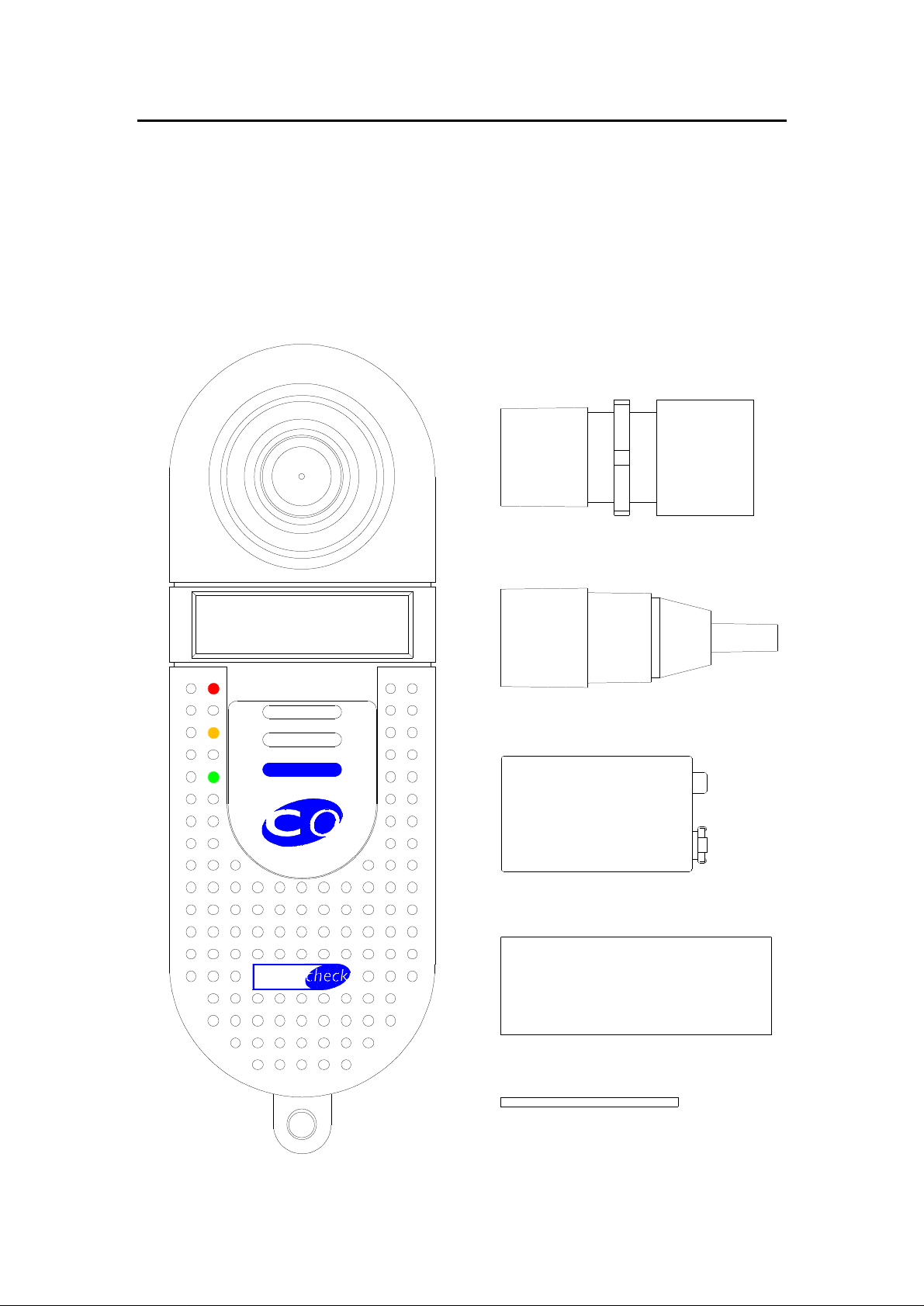
Smoke Check system overview.
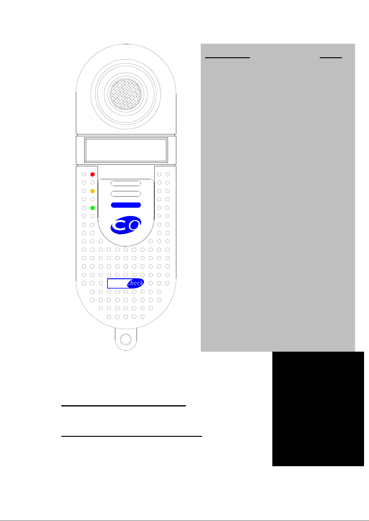
The Micro Medical Smoke Check consists of a hand held microcomputer
unit (1) incorporating a CO sensor and is supplied with a mouthpiece
adapter with integral one way valve and flow restrictor (2) together with
disposable cardboard mouthpieces (5).
The microcomputer unit is powered by a single alkaline PP3 battery (4)
and is supplied with a reducing connector (3) and rod (6) for calibration
1
2
ON
OFF
smoke
3
4
5
6
3

The CO sensor is an electrochemical fuel cell, and works through the
reaction of carbon monoxide at one electrode and oxygen (from ambient
air) at the other. This reaction generates an electrical current proportional
to the concentration of CO exposed to the sensing surface of the fuel cell.
The current output signal from the sensor is conditioned using a current to
voltage converter and is applied to an analogue port of the
microprocessor.
When the unit is first switched on the microprocessor records the baseline
analogue reading and uses this value to auto zero the instrument.
The subject is then requested to breathe in maximally, hold the breath for
20 seconds, and then to expire fully through the mouthpiece connected to
the Smoke Check with the mouthpiece adapter. As an aid to timing the
breath holding period the legend ‘WAIT’ is displayed until the 20 seconds
has elapsed.
The microprocessor then records the peak value obtained and displays
this on a custom LCD display in the ranges given below.
As a quick guide to the estimated smoking level, red, amber and green
indicator lights are also provided. The following levels of CO activate
these lights:
CO(ppm) Cigarette consumption Indicator
0 - 6 Non smoker Green
7 -10 Light smoker Amber
11 – 20 Heavy smoker Red
20+ Very heavy smoker Flashing red + alarm
4
 Loading...